ee1214 electrical engineering laboratory€¦ · web viewspeed control of dc shunt motor (armature,...
TRANSCRIPT

131354 ELECTRICAL ENGINEERING LABORATORY
LIST OF EXPERIMENTS
Load test on DC Shunt & DC Series motor
O.C.C & Load characteristics of DC Shunt and DC Series generator
Speed control of DC shunt motor (Armature, Field control)
Load test on single phase transformer
O.C & S.C Test on a single phase transformer
Regulation of an alternator by EMF & MMF methods.
V curves and inverted V curves of synchronous Motor
Load test on three phase squirrel cage Induction motor
Speed control of three phase slip ring Induction Motor
Load test on single phase Induction Motor.
Study of DC & AC Starters


LOAD TEST ON DC SERIES MOTOR
Ex. No. DateAIM:
To perform load test on the given D.C series motor and to obtain the performance
characteristics.
APPARATUS REQUIRED:
S.No
Name of the
apparatus Type Range Quantity
FORMULAE:
PRECAUTIONS:
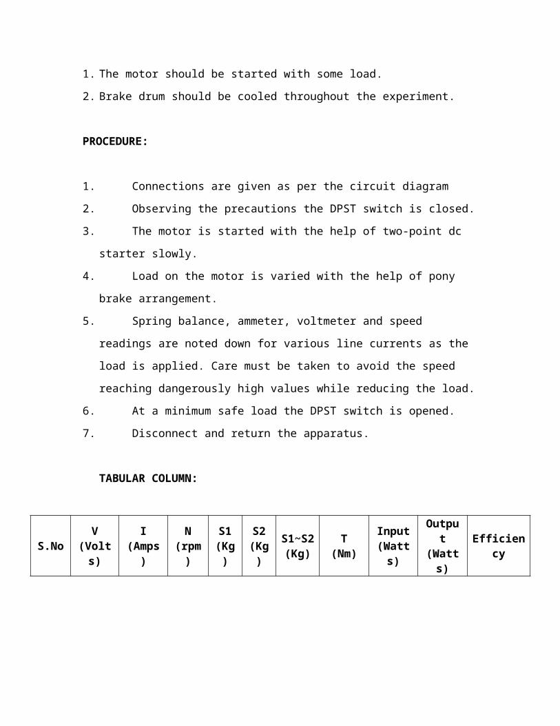
1. The motor should be started with some load.
2. Brake drum should be cooled throughout the experiment.
PROCEDURE:

1. Connections are given as per the circuit diagram
2. Observing the precautions the DPST switch is closed.
3. The motor is started with the help of two-point dc starter slowly.
4. Load on the motor is varied with the help of pony brake arrangement.
5. Spring balance, ammeter, voltmeter and speed readings are noted down for
various line currents as the load is applied. Care must be taken to avoid the speed
reaching dangerously high values while reducing the load.
6. At a minimum safe load the DPST switch is opened.
7. Disconnect and return the apparatus.
TABULAR COLUMN:
S.No V(Volts)
I(Amps)
N(rpm)
S1(Kg)
S2(Kg)
S1~S2(Kg)
T(Nm)
Input(Watts)
Output(Watts) Efficiency
RESULT:
The load test on the given D.C series motor was conducted and its performance
characteristics were drawn and the following conclusion can be given based on the
performance curves


LOAD TEST ON DC SHUNT MOTOR
Ex. No. Date
AIM: To perform load test on the given D.C shunt motor and to obtain the
performance characteristics.
APPARATUS REQUIRED:
Sl.No. Name Range Type Quantity
1 Voltmeter MC
2 Ammeter MC
3 Rheostat Wire wound
4 Connecting
wires
5 Tachometer Digital
FORMULAE:
PRECAUTIONS:
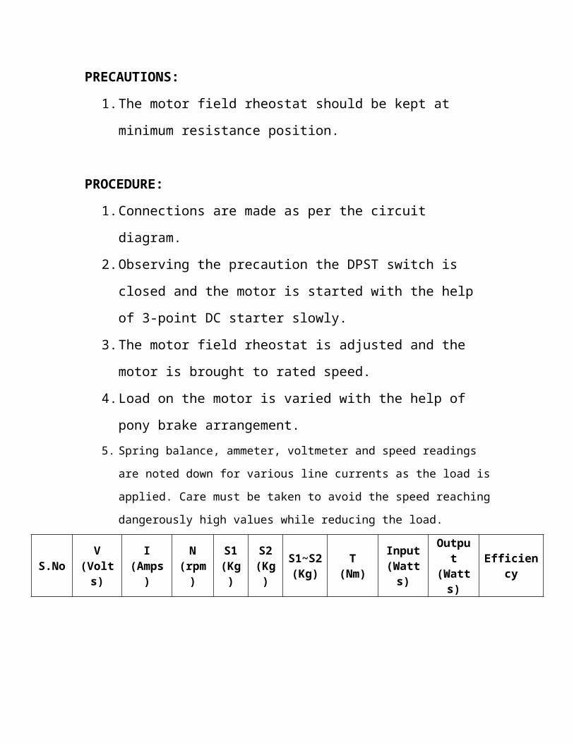
1. The motor field rheostat should be kept at minimum resistance
position.
PROCEDURE:
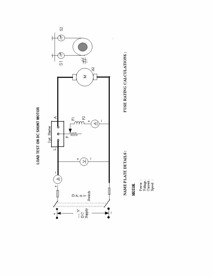
1. Connections are made as per the circuit diagram.
2. Observing the precaution the DPST switch is closed and the motor is
started with the help of 3-point DC starter slowly.
3. The motor field rheostat is adjusted and the motor is brought to rated
speed.
4. Load on the motor is varied with the help of pony brake arrangement.5. Spring balance, ammeter, voltmeter and speed readings are noted down for
various line currents as the load is applied. Care must be taken to avoid the speed
reaching dangerously high values while reducing the load.
S.No V(Volts)
I(Amps)
N(rpm)
S1(Kg)
S2(Kg)
S1~S2(Kg)
T(Nm)
Input(Watts)
Output(Watts) Efficiency
6. At a minimum safe load the DPST switch is opened.
7. Disconnect and return the apparatus.TABULAR COLUMN:
MODEL GRAPH:

RESULT:
The load test on the given D.C shunt motor was conducted and its performance
characteristics were drawn and the following conclusion can be given based on the
performance curves
OPEN CIRCUIT CHARACTERISTICS OF SEPARATELY EXCITIED DC GENERATOR
Aim:
To draw open circuit characteristics of the given separately excited DC
generator.
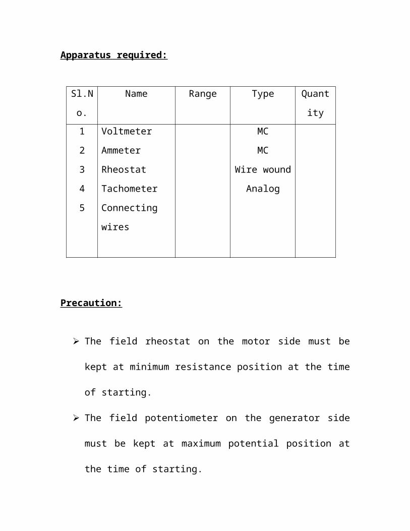
Apparatus required:
Sl.No. Name Range Type Quantity
1
2
3
4
5
Voltmeter
Ammeter
Rheostat
Tachometer
Connecting wires
MC
MC
Wire wound
Analog
Precaution:
The field rheostat on the motor side must be kept at minimum
resistance position at the time of starting.
The field potentiometer on the generator side must be kept at
maximum potential position at the time of starting.
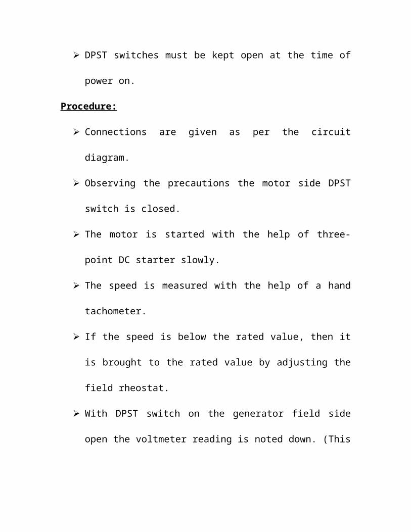
DPST switches must be kept open at the time of power on.
Procedure:
Connections are given as per the circuit diagram.
Observing the precautions the motor side DPST switch is closed.
The motor is started with the help of three- point DC starter slowly.
The speed is measured with the help of a hand tachometer.
If the speed is below the rated value, then it is brought to the rated
value by adjusting the field rheostat.

With DPST switch on the generator field side open the voltmeter
reading is noted down. (This is the residual voltage at the rated speed
at which the motor-generator set is running now.)
The DPST switch on the generator field side is closed.
By adjusting the potentiometer on the generator field side suitably for
various increasing field currents, note down the terminal voltages till
around 125% of the rated voltage. The speed is maintained constant
throughout this process.
The generator terminal voltage is minimized to zero.
The speed is brought down to minimum value and the motor is
switched off with the help of DPST switch. (Note the starter holding
coil releasing the handle else bring it back to start position)
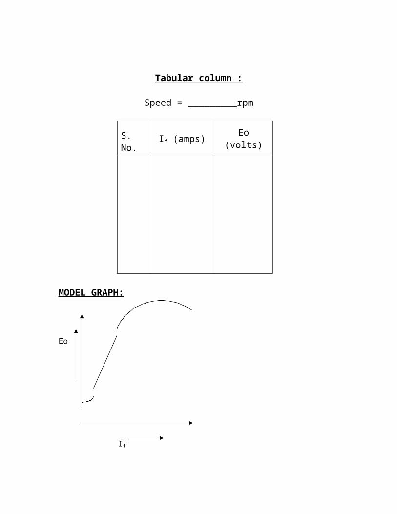
Tabular column :
Speed = _________rpm

S. No. If (amps) Eo (volts)
MODEL GRAPH:
Eo
If
Result
REGULATION OF ALTERNATOR BY EMF METHOD
Aim:
To pre-determine the regulation of alternator by emf method.
Apparatus required:
Sl.No. Name Range Type Quantity
1
2
3
4
5
Voltmeter
Ammeter
Ammeter
Rheostat
Connecting wires
MI
MC,
MI
Wire wound
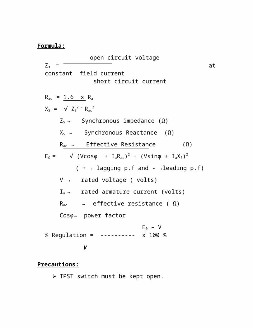
Formula:
open circuit voltage Zs = at constant field current short circuit current Rac = 1.6 x Ra
XS = √ ZS2 – Rac
2
ZS → Synchronous impedance (Ω)
XS → Synchronous Reactance (Ω)
Rac → Effective Resistance (Ω)
EO = √ (Vcosφ + IaRac)2 + (Vsinφ ± IaXS)2
( + → lagging p.f and - →leading p.f)
V → rated voltage ( volts)
Ia → rated armature current (volts)
Rac → effective resistance ( Ω)

Cosφ→ power factor
E0 – V % Regulation = ---------- x 100 %
V
Precautions:
TPST switch must be kept open.
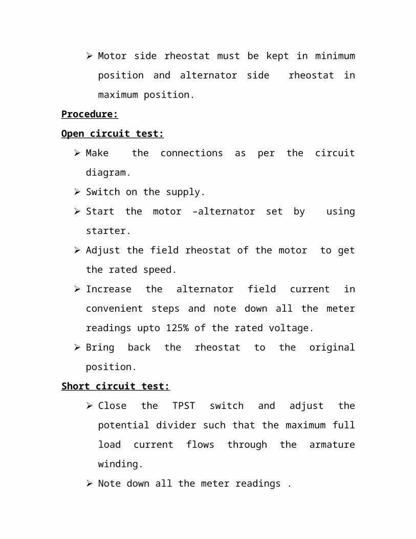
Motor side rheostat must be kept in minimum position and
alternator side rheostat in maximum position.
Procedure:
Open circuit test:
Make the connections as per the circuit diagram.
Switch on the supply.
Start the motor –alternator set by using starter.
Adjust the field rheostat of the motor to get the rated speed.
Increase the alternator field current in convenient steps and note down
all the meter readings upto 125% of the rated voltage.
Bring back the rheostat to the original position.
Short circuit test:
Close the TPST switch and adjust the potential divider such that
the maximum full load current flows through the armature
winding.
Note down all the meter readings .
Bring back the rheostats to original position and switch off the
supply.
Tabulation :
Open circuit test:
Sl.No If
(Amperes)Open circuit voltage
E0( Volts)
Short circuit test:
If2 (Amperes) Isc (Amperes)
MODEL GRAPH:
EoIsc
If
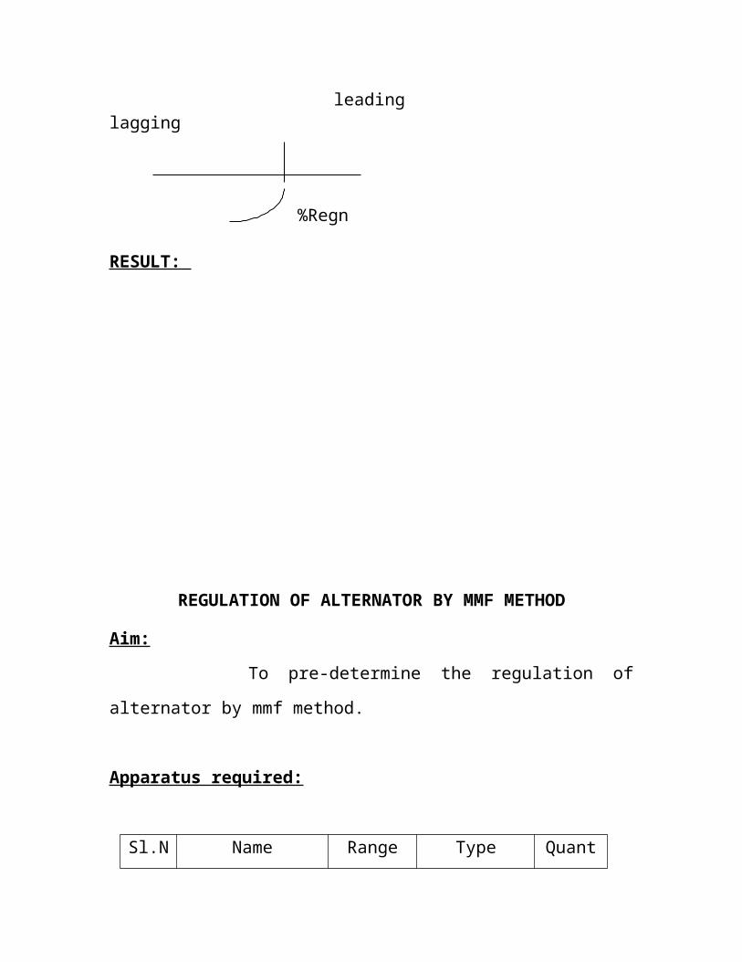
Cosφ % Regulation

leading lagging0
0.20.60.81
%Regn
leading lagging
%Regn
RESULT:

REGULATION OF ALTERNATOR BY MMF METHOD
Aim:
To pre-determine the regulation of alternator by mmf method.
Apparatus required:
Sl.No. Name Range Type Quantity
1
2
3
4
5
Voltmeter
Ammeter
Ammeter
Rheostat
Connecting wires
MI
MC,
MI
Wire wound
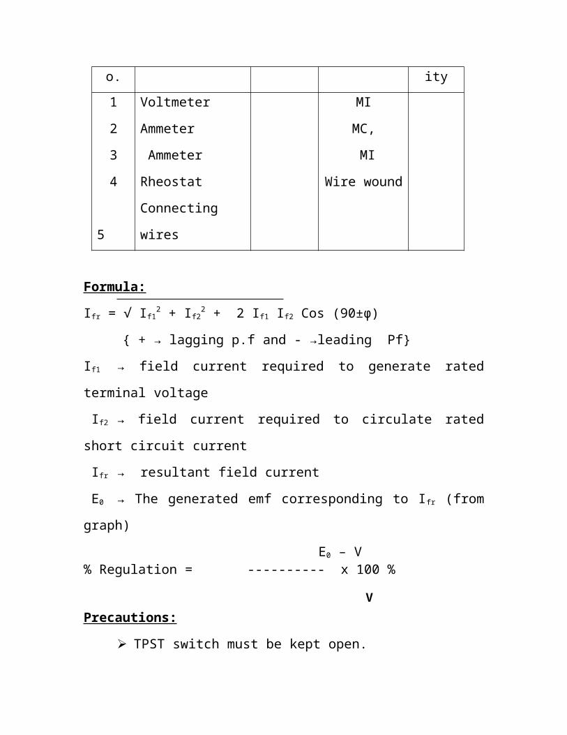
Formula:
Ifr = √ If12 + If2
2 + 2 If1 If2 Cos (90±φ)
+ → lagging p.f and - →leading Pf
If1 → field current required to generate rated terminal voltage
If2 → field current required to circulate rated short circuit current
Ifr → resultant field current
E0 → The generated emf corresponding to Ifr (from graph)
E0 – V % Regulation = ---------- x 100 %
V Precautions:
TPST switch must be kept open.
Motor side rheostat must be kept in minimum position and
alternator side rheostat in maximum position.
Procedure:
Open circuit test:
Make the connections as per the circuit diagram.
Switch on the supply.
Start the motor –alternator set by using starter.
Adjust the field rheostat of the motor to get the rated speed.
Increase the alternator field current in convenient steps and note down
all the meter readings upto 125% of the rated voltage.
Bring back the rheostat to the original position.
Short circuit test:
Close the TPST switch and adjust the potential divider such that
the maximum full load current flows through the armature
winding.
Note down all the meter readings .
Bring back the rheostats to original position and switch off the
supply.
Tabulation :
Open circuit test:
Sl.No If
(Amperes)Open circuit voltage
E0( Volts)
Short circuit test:
If2 (Amperes) Isc (Amperes)
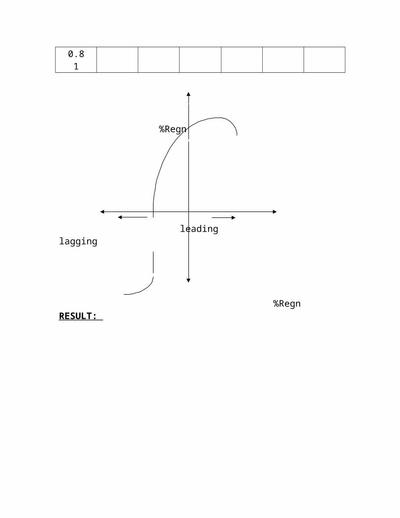
Cosφ Lagging pf Leading pfIfr E0 %R Ifr E0 %R
00.20.60.81
%Regn
leading lagging
%RegnRESULT:


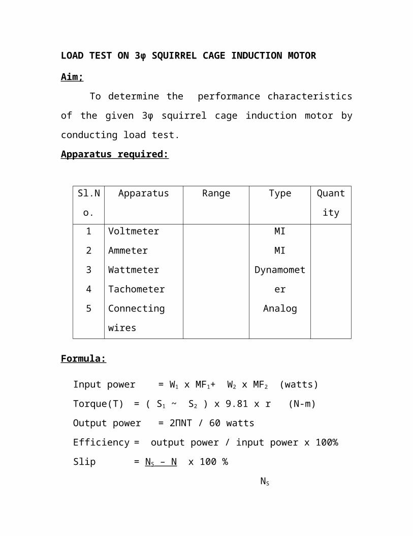
LOAD TEST ON 3φ SQUIRREL CAGE INDUCTION MOTOR
Aim;
To determine the performance characteristics of the given 3φ squirrel
cage induction motor by conducting load test.
Apparatus required:
Sl.No. Apparatus Range Type Quantity
1
2
3
4
5
Voltmeter
Ammeter
Wattmeter
Tachometer
Connecting wires
MI
MI
Dynamometer
Analog
Formula:
Input power = W1 x MF1+ W2 x MF2 (watts)
Torque(T) = ( S1 ~ S2 ) x 9.81 x r (N-m)
Output power = 2ΠNT / 60 watts
Efficiency = output power / input power x 100%
Slip = NS – N x 100 %
NS
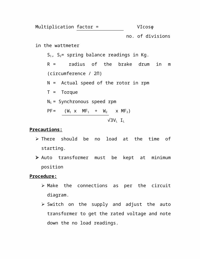
Multiplication factor = VIcosφ
no. of divisions in the wattmeter
S1, S2= spring balance readings in Kg.
R = radius of the brake drum in m (circumference / 2Π)
N = Actual speed of the rotor in rpm
T = Torque
NS = Synchronous speed rpm
PF = (W1 x MF1 + W2 x MF2)
√3VL IL
Precautions:
There should be no load at the time of starting.
Auto transformer must be kept at minimum position
Procedure:
Make the connections as per the circuit diagram.
Switch on the supply and adjust the auto transformer to get the
rated voltage and note down the no load readings.
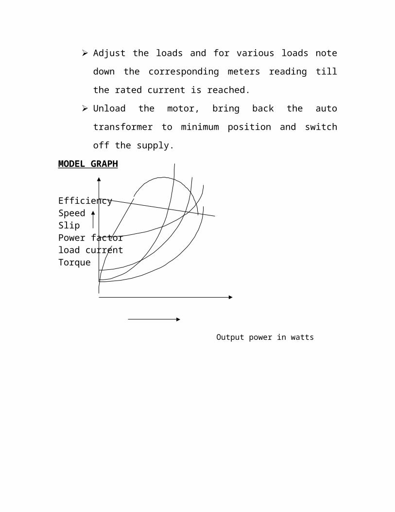
Adjust the loads and for various loads note down the
corresponding meters reading till the rated current is reached.
Unload the motor, bring back the auto transformer to minimum
position and switch off the supply.
MODEL GRAPH
EfficiencySpeedSlipPower factorload currentTorque
Output power in watts


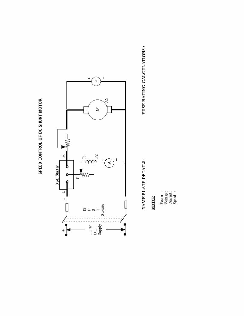
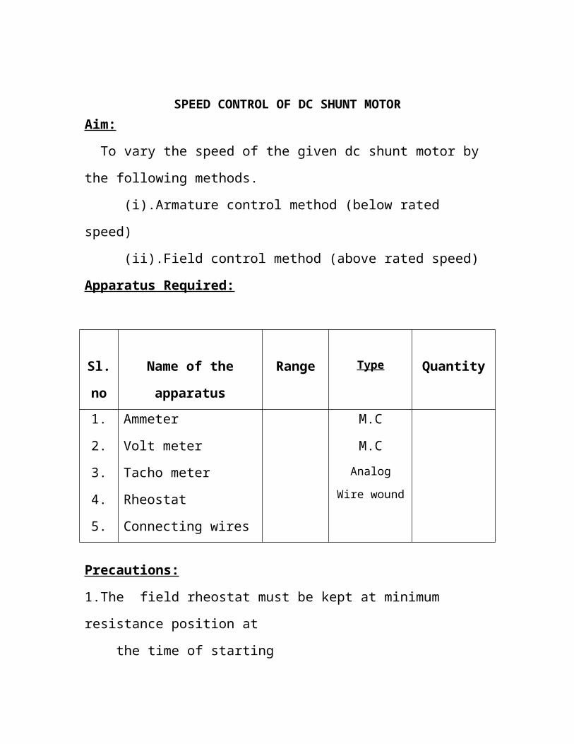
SPEED CONTROL OF DC SHUNT MOTORAim:
To vary the speed of the given dc shunt motor by the following methods.
(i).Armature control method (below rated speed)
(ii).Field control method (above rated speed)
Apparatus Required:
Sl.no Name of the apparatus Range Type Quantity
1.
2.
3.
4.
5.
Ammeter
Volt meter
Tacho meter
Rheostat
Connecting wires
M.C
M.CAnalog
Wire wound
Precautions:
1.The field rheostat must be kept at minimum resistance position at
the time of starting
2. The armature rheostat must be kept at maximum resistance position at
the time of starting
Procedure:
(i).Armature control method:
Make the connections as per the circuit diagram
Switch on the supply
Keep the field current constant and for different armature voltage (by
varying armature rheostat ) note down the corresponding speed.
Bring back the rheostat to initial position and switch off the supply
(ii) Field control method
Switch on the supply
Start the motor by closing the DPST switch
Keep the armature voltage constant and for various field current note
down the corresponding speed.
Bring back the rheostat to initial position and switch off the supply
MODEL GRAPH
Armature Control method Field control method
Speed rpm Speed
rpm
Armature voltage (volts) Field current(amps)
(i).Armature control method:
Field current (If ) =
SL.No Armature voltage(volts)
Speed(rpm)

(ii) Field control method
Armature voltage (Va ) =
SL.No Field current(amps)
Speed(rpm)
Result:
LOAD TEST ON SINGLE PHASE TRANSFORMER
Aim:
To perform load test on a single phase transformer and determine its
performance characteristicsApparatus Required:
Sl.no Name of the apparatus Range Type Quantity
1.
2.
3.
4.
Ammeter
Volt meter
Watt meter
Connecting wires
M.I
MI.
Dynamo meter
Formulae:
Input power = W1 x M.F1 watts
Output power = W2 x M.F2 watts
Output power Efficiency = X 100 %
Input power E 02 - V 2
Regulation = X 100 %
E 02
E 02 - No load secondary voltage
V 2 - Secondary voltage at various loads
M.F – Multiplication factor
W1, W2 - Wattmeter readingsMultiplication factor (M.F) = V I cos
No of divisions in the watt meter
Precautions:
Auto transformer must be kept at minimum potential point
There should be no load at the time of starting the experiment
Procedure:
Make the connections as per the circuit diagram
Switch on the supply and vary the autotransformer to get rated
primary voltage
Note down the no load readings
Add the load in steps and note down all the meter readings till the
rated secondary current is reached
Remove the load and bring back the autotransformer to original
position.
Switch off the supply
MODEL GRAPH
Efficiency Regulation
%
Output power in watts
OC AND SC TEST OF SINGLE PHASE TRANSFORMER
Aim:
To perform open circuit and short circuit test on a single phase transformer and
predetermine the efficiency at various loads and also draw the equivalent circuit.
Apparatus Required:
Sl.no Name of the apparatus Range Type Quantity
1.
2.
3.
4.
Ammeter
Volt meter
Watt meter
Connecting wires
M.I
MI.
Dynamo meter
Formulae:
From open circuit test:
W0 = V0 I0 Cos 0 ( watts)
Cos 0 = W0
V0 I0
I w = I0 Cos 0 ( Iron loss component)
I = I0 Sin 0 ( magnetizing component)
R0 = V0 / I w (resistance to represent core loss)
X0 = V0 / I (reactance to represent magnetizing component)
W0 = No load input = core loss = Wi = Iron lossI0 - No load input current
V0 – No load rated input voltage
From short circuit test:
R01 = Wsc
Isc 2
Z01 = Vsc
IscX01 = Z01
2 - R012
R01 - equivalent resistance of transformer referred to primary side
X01 - equivalent reactance of transformer referred to primary side
Z01 - equivalent impedance of transformer referred to primary side
Wsc – Full load copper loss
R02 = R01 x K 2
X02 = X01 x K 2
Z02 = Z01 x K 2
% Regulation = I2 R02 Cos + I2 X02 Sin X 100 %
V2
+ lagging Power factor
- leading powerfactor
Cos - Power factor
Efficiency at various loads = X * KVA * P.f * 100 %
X * KVA * P.f + Wi + X 2 Wsc
X – Load ratio
Precautions:
Auto transformer must be kept at minimum potential pointProcedure:
Open circuit test:
Make the connections as per the circuit diagram
Switch on the supply and vary the autotransformer to get rated voltage
Note down ammeter ,voltmeter and wattmeter readings.
Bring back the autotransformer to original position.
Switch off the supply
Short circuit test:
Make the connections as per the circuit diagram
Switch on the supply and vary the autotransformer to get rated short
circuit current.
Note down ammeter ,voltmeter and wattmeter readings.
Bring back the autotransformer to original position.
Switch off the supply
Equivalent circuit referred to primary side:
Equivalent circuit referred to secondary side:
Model Graph
Open circuit test
Short circuit test:
Load ratio X
Output power
upf 0.8
RESULT
Sl.]no
Vovolts
Ioamps
Wodiv
Wo x M.Fwatts
Sl.]no
Vscvolts
Iscamps
Wscdiv
Wsc x M.Fwatts