energy storage systems – grid connection using synchronverters
TRANSCRIPT

2016 ISCEE International Conference on the Science of Electrical Engineering
978-1-5090-2152-9/16/$31.00 ©2016 IEEE
Energy Storage Systems – Grid Connection Using Synchronverters
Gal Barzilai Lior Marcus George Weiss School of Electrical Engineering
Tel Aviv University Tel Aviv, Israel
Abstract—We investigate the design of future energy storage systems by exploring one particular solution, in simulations. We use Lithium-ion batteries for storage, a dual active bridge (DAB) for DC to DC conversion and a synchronverter to transfer energy from the DC bus to the utility grid. We show how some recent improvements to the synchronverter algorithm can be combined with a battery management algorithm that will charge or discharge the batteries to achieve a maximal profit for the operator of the storage station, while at the same time contributing to the stability of the grid by providing frequency droop, voltage droop inertia and fault ride-through. We discuss different open loop and closed loop control algorithms for the DAB as well as for the overall system that will further increase its efficiency. We simulate the use of two DABs, one for the positive DC voltage and one for the negative one, with a 5KW three-level synchronverter working on the 230V grid.
Keywords—Synchronverter; energy storage system; dual active bridge; droop control; model predictive control.
I. INTRODUCTION
Renewable energy sources are becoming more and more popular, for economic and environmental reasons [1]. In recent years scientific advances have made solar panels and other renewable energy sources cheaper and more efficient. However renewable energy sources suffer from intermittency (variable and partly unpredictable production rate) and lower reliability in comparison to conventional energy sources, and their production cannot be tuned to the demand curve. The obvious solution to address this is the use of energy storage [2] systems that can inject power to the utility grid according to the demand at hand. Energy storage systems can also contribute in potential to the stability of the grid and to the grid quality [3-4,18]. Although today's energy storage systems prices are prohibitively high, we believe that in the near future their prices will be reduced, which will enable their widespread use. Energy storage system injecting energy to the grid using conventional inverters can damage the stability of the grid, potentially leading to blackouts that have a huge economic cost. This problem is associated with the large-scale penetration of inverters into the power grid, regardless of their role. A new type of inverters, called synchronverters, have been developed to address this issue. They mimic synchronous generators, and crucially they add inertia to the electricity grid, which helps to stabilize it. Their usage in grid connected energy storage systems can facilitate the market acceptance of such storage systems, as well as increasing the grid stability
rather than decreasing it. Typically, a battery based energy storage system will have a DC bus at an approximately constant voltage that will not be the same as the battery voltage. Thus, a typical battery based energy storage system will contain two converters, one DC/DC converter to interface between the battery and the DC bus, and the inverter mentioned earlier that is the interface between the DC bus and the utility grid. The control system of the storage system has to oversee both converters, ensure safe operation and fault ride-through, optimize from an economic point of view (using market prices), send status reports to the grid operator and receive demands (such as active and reactive power) both from the grid operator and from the local operator. This requires a careful design of the control system.
As already mentioned, due to the high price of batteries, energy storage systems are still at a research and development stage, and a myriad of solutions are being explored by large companies as well as by academia. We contribute to this effort by designing an experimental energy storage system based on Lithium-ion batteries, a pair of dual active bridges (DABs) which we believe will be the dominant technology for bi-directional DC/DC power conversion with galvanic isolation, and a synchronverter. Our system is of very small scale (up to 5KW power) but it has all the features that a much larger system would have.
A DAB converter can be operated with zero voltage switching (ZVS), thus significantly reducing the power losses of the DC/DC converter, and of the overall system. One control algorithm used in such a converter is called phase shifting, also referred to as single phase shifting (SPS). This algorithm is simple to implement because we control only one variable, the phase shift. We will show solutions to both voltage tracking and to load response. SPS gives good performance when the ratio between the voltages is close to the transformer windings ratio. For batteries this is a reasonable assumption but we will also mention more advanced control algorithms, such as triple-phase-shifting (TPS).
The rest of this paper is organized as follows: In Section II the synchronverter algorithm with recent developments is shortly reviewed. In Section III we examine an optimal energy management algorithm that uses the variable electricity price as an input, and is based on model predictive control. In Sections IV we will survey the architecture and control of DAB, in V we present simulation results and in VI we present conclusions.
2016 ISCEE International Conference on the Science of Electrical Engineering
II. SYNCHRONVERTER ALGORITHM LATEST DEVELOPMENT
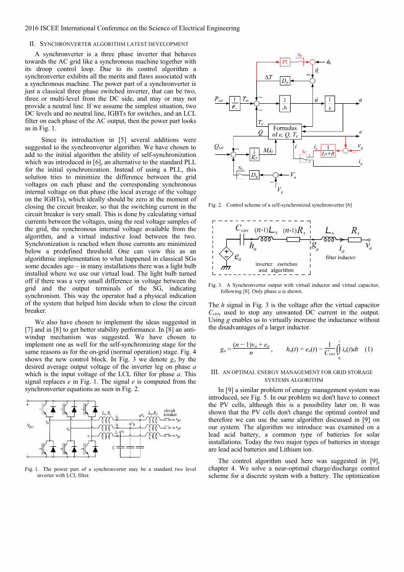
A synchronverter is a three phase inverter that behaves towards the AC grid like a synchronous machine together with its droop control loop. Due to its control algorithm a synchronverter exhibits all the merits and flaws associated with a synchronous machine. The power part of a synchronverter is just a classical three phase switched inverter, that can be two, three or multi-level from the DC side, and may or may not provide a neutral line. If we assume the simplest situation, two DC levels and no neutral line, IGBTs for switches, and an LCL filter on each phase of the AC output, then the power part looks as in Fig. 1.
Since its introduction in [5] several additions were suggested to the synchronverter algorithm. We have chosen to add to the initial algorithm the ability of self-synchronization which was introduced in [6], an alternative to the standard PLL for the initial synchronization. Instead of using a PLL, this solution tries to minimize the difference between the grid voltages on each phase and the corresponding synchronous internal voltage on that phase (the local average of the voltage on the IGBTs), which ideally should be zero at the moment of closing the circuit breaker, so that the switching current in the circuit breaker is very small. This is done by calculating virtual currents between the voltages, using the real voltage samples of the grid, the synchronous internal voltage available from the algorithm, and a virtual inductive load between the two. Synchronization is reached when those currents are minimized below a predefined threshold. One can view this as an algorithmic implementation to what happened in classical SGs some decades ago – in many installations there was a light bulb installed where we use our virtual load. The light bulb turned off if there was a very small difference in voltage between the grid and the output terminals of the SG, indicating synchronism. This way the operator had a physical indication of the system that helped him decide when to close the circuit breaker.
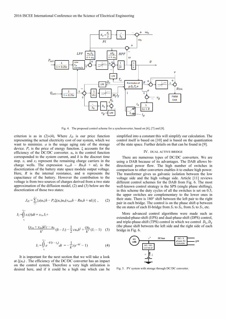
We also have chosen to implement the ideas suggested in [7] and in [8] to get better stability performance. In [8] an anti-windup mechanism was suggested. We have chosen to implement one as well for the self-synchronizing stage for the same reasons as for the on-grid (normal operation) stage. Fig. 4 shows the new control block. In Fig. 3 we denote ga by the desired average output voltage of the inverter leg on phase a which is the input voltage of the LCL filter for phase a. This signal replaces e in Fig. 1. The signal e is computed from the synchronverter equations as seen in Fig. 2.
Fig. 1. The power part of a synchronverter may be a standard two level
inverter with LCL filter.
Fig. 2. Control scheme of a self-synchronized synchronverter [6]
Fig. 3. A Synchronverter output with virtual inductor and virtual capacitor,
following [8]. Only phase a is shown.
The h signal in Fig. 3 is the voltage after the virtual capacitor Cvirt, used to stop any unwanted DC current in the output. Using g enables us to virtually increase the inductance without the disadvantages of a larger inductor.
ga = (n − 1)va + ea
n , ha(t) = ea(t) − 1
Cvirt
0
t
ia(t)dt (1)
III. AN OPTIMAL ENERGY MANAGEMENT FOR GRID STORAGE
SYSTEMS ALGORITHM
In [9] a similar problem of energy management system was introduced, see Fig. 5. In our problem we don't have to connect the PV cells, although this is a possibility later on. It was shown that the PV cells don't change the optimal control and therefore we can use the same algorithm discussed in [9] on our system. The algorithm we introduce was examined on a lead acid battery, a common type of batteries for solar installations. Today the two major types of batteries in storage are lead acid batteries and Lithium ion.
The control algorithm used here was suggested in [9], chapter 4. We solve a near-optimal charge/discharge control scheme for a discrete system with a battery. The optimization
2016 ISCEE International Conference on the Science of Electrical Engineering
Fig. 4. The proposed control scheme for a synchronverter, based on [6], [7] and [8].
criterion is as in (2)-(4), Where Jd2 is our price function representing the actual electricity cost of our system, which we want to minimize. a is the usage aging rate of the storage device. Pe is the price of energy function. ξ accounts for the efficiency of the DC/DC converter. un is the control function corresponded to the system current, and δ is the discreet time step. x1 and x2 represent the remaining charge carriers in the charge wells. The expression vminδ – Runδ + αI2 is the discretization of the battery state space module output voltage. Here, R is the internal resistance, and α represents the capacitance of the battery. However the contribution to the voltage is from two sources of charges derived from a two state approximation of the diffusion model, (2) and (3) below are the discretization of those two states:
Jd2 = n=1
N−1
{a|un|δ − Peξ(un)un(vminδ − Runδ + αI2)} , (2)
I2 =tn
tn+1
x1(t)dt = x1n I1+
(x1n + x2n)k'c − un
k' (δ – I1) − 12 cunδ2 +
cunk' (I1 – 1) (3)
I1 = tn
tn+1
e−k'(t – tn)
dt = − 1k' (e
−δk' − 1) (4)
It is important for the next section that we will take a look at ξ(un) . The efficiency of the DC/DC converter has an impact on the control system. Therefore a very high utilization is desired here, and if it could be a high one which can be
simplified into a constant this will simplify our calculation. The control itself is based on [10] and is based on the quantization of the state space. Further details on that can be found in [9].
IV. DUAL ACTIVE BRIDGE
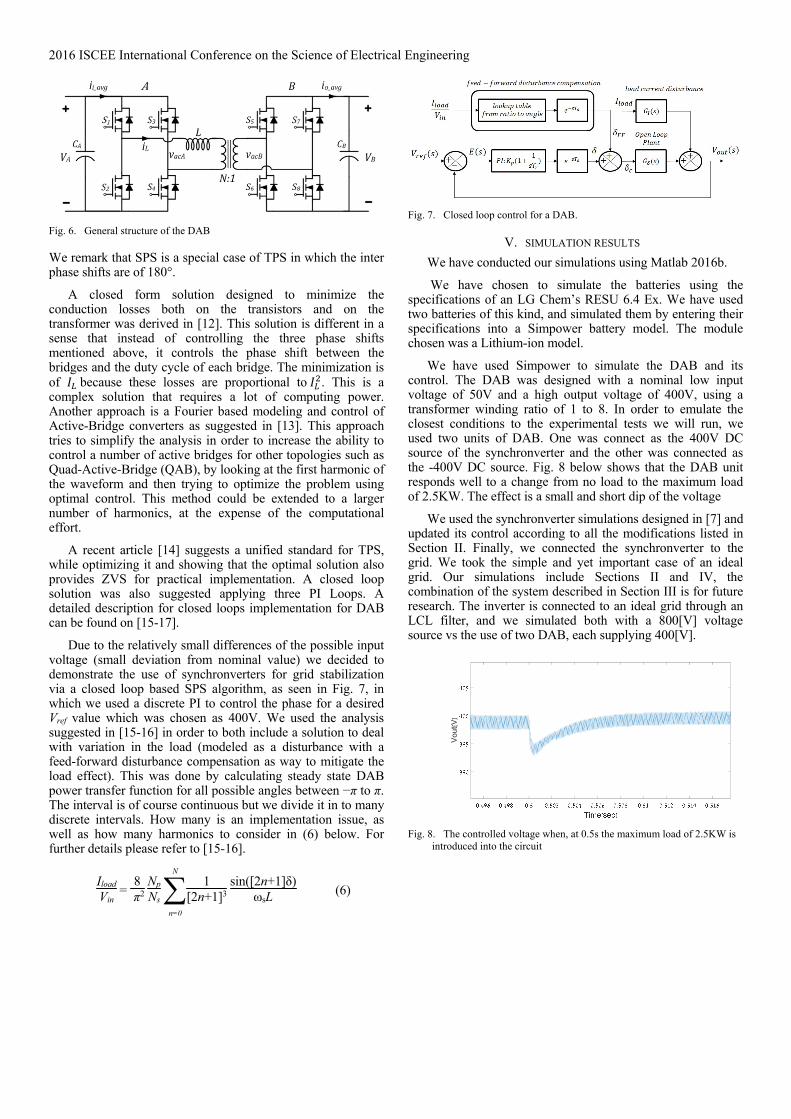
There are numerous types of DC/DC converters. We are using a DAB because of its advantages. The DAB allows bi-directional power flow. The high number of switches in comparison to other converters enables it to endure high power. The transformer gives us galvanic isolation between the low voltage side and the high voltage side. Article [11] reviews different control schemes for the DAB from Fig. 6. The most well-known control strategy is the SPS (single phase shifting), in this scheme the duty cycles of all the switches is set on 0.5, the upper switches are complementary to the lower ones in their state. There is 180° shift between the left pair to the right pair in each bridge. The control is on the phase shift φ between the on states of each H-bridge from S1 to S5, from S3 to S7, etc.
More advanced control algorithms were made such as extended-phase-shift (EPS) and dual-phase-shift (DPS) control, and triple-phase-shift (TPS) control in which we control , (the phase shift between the left side and the right side of each bridge in Fig. 6.
Fig. 5. PV system with storage through DC/DC converter.
2016 ISCEE International Conference on the Science of Electrical Engineering
Fig. 6. General structure of the DAB
We remark that SPS is a special case of TPS in which the inter phase shifts are of 180°.
A closed form solution designed to minimize the conduction losses both on the transistors and on the transformer was derived in [12]. This solution is different in a sense that instead of controlling the three phase shifts mentioned above, it controls the phase shift between the bridges and the duty cycle of each bridge. The minimization is of because these losses are proportional to . This is a complex solution that requires a lot of computing power. Another approach is a Fourier based modeling and control of Active-Bridge converters as suggested in [13]. This approach tries to simplify the analysis in order to increase the ability to control a number of active bridges for other topologies such as Quad-Active-Bridge (QAB), by looking at the first harmonic of the waveform and then trying to optimize the problem using optimal control. This method could be extended to a larger number of harmonics, at the expense of the computational effort.
A recent article [14] suggests a unified standard for TPS, while optimizing it and showing that the optimal solution also provides ZVS for practical implementation. A closed loop solution was also suggested applying three PI Loops. A detailed description for closed loops implementation for DAB can be found on [15-17].
Due to the relatively small differences of the possible input voltage (small deviation from nominal value) we decided to demonstrate the use of synchronverters for grid stabilization via a closed loop based SPS algorithm, as seen in Fig. 7, in which we used a discrete PI to control the phase for a desired Vref value which was chosen as 400V. We used the analysis suggested in [15-16] in order to both include a solution to deal with variation in the load (modeled as a disturbance with a feed-forward disturbance compensation as way to mitigate the load effect). This was done by calculating steady state DAB power transfer function for all possible angles between −π to π. The interval is of course continuous but we divide it in to many discrete intervals. How many is an implementation issue, as well as how many harmonics to consider in (6) below. For further details please refer to [15-16].
IloadVin
= 8
π2 NpNs
n=0
N1
[2n+1]3 sin([2n+1]δ)
ωsL (6)
Fig. 7. Closed loop control for a DAB.
V. SIMULATION RESULTS
We have conducted our simulations using Matlab 2016b.
We have chosen to simulate the batteries using the specifications of an LG Chem’s RESU 6.4 Ex. We have used two batteries of this kind, and simulated them by entering their specifications into a Simpower battery model. The module chosen was a Lithium-ion model.
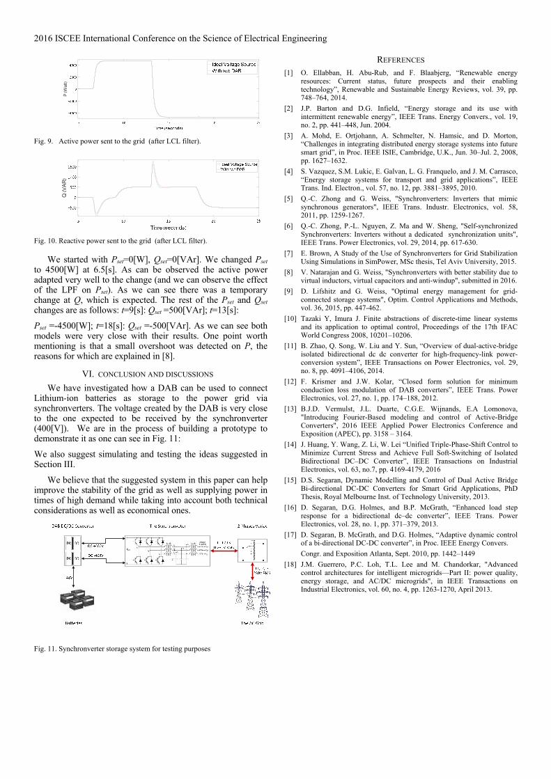
We have used Simpower to simulate the DAB and its control. The DAB was designed with a nominal low input voltage of 50V and a high output voltage of 400V, using a transformer winding ratio of 1 to 8. In order to emulate the closest conditions to the experimental tests we will run, we used two units of DAB. One was connect as the 400V DC source of the synchronverter and the other was connected as the -400V DC source. Fig. 8 below shows that the DAB unit responds well to a change from no load to the maximum load of 2.5KW. The effect is a small and short dip of the voltage
We used the synchronverter simulations designed in [7] and updated its control according to all the modifications listed in Section II. Finally, we connected the synchronverter to the grid. We took the simple and yet important case of an ideal grid. Our simulations include Sections II and IV, the combination of the system described in Section III is for future research. The inverter is connected to an ideal grid through an LCL filter, and we simulated both with a 800[V] voltage source vs the use of two DAB, each supplying 400[V].
Fig. 8. The controlled voltage when, at 0.5s the maximum load of 2.5KW is
introduced into the circuit
Vou
t[V]
2016 ISCEE International Conference on the Science of Electrical Engineering
Fig. 9. Active power sent to the grid (after LCL filter).
Fig. 10. Reactive power sent to the grid (after LCL filter).
We started with Pset=0[W], Qset=0[VAr]. We changed Pset to 4500[W] at 6.5[s]. As can be observed the active power adapted very well to the change (and we can observe the effect of the LPF on Pset). As we can see there was a temporary change at Q, which is expected. The rest of the Pset and Qset changes are as follows: t=9[s]: Qset =500[VAr]; t=13[s]:
Pset =-4500[W]; t=18[s]: Qset =-500[VAr]. As we can see both models were very close with their results. One point worth mentioning is that a small overshoot was detected on P, the reasons for which are explained in [8].
VI. CONCLUSION AND DISCUSSIONS
We have investigated how a DAB can be used to connect Lithium-ion batteries as storage to the power grid via synchronverters. The voltage created by the DAB is very close to the one expected to be received by the synchronverter (400[V]). We are in the process of building a prototype to demonstrate it as one can see in Fig. 11:
We also suggest simulating and testing the ideas suggested in Section III.
We believe that the suggested system in this paper can help improve the stability of the grid as well as supplying power in times of high demand while taking into account both technical considerations as well as economical ones.
Fig. 11. Synchronverter storage system for testing purposes
REFERENCES [1] O. Ellabban, H. Abu-Rub, and F. Blaabjerg, “Renewable energy
resources: Current status, future prospects and their enabling technology”, Renewable and Sustainable Energy Reviews, vol. 39, pp. 748–764, 2014.
[2] J.P. Barton and D.G. Infield, “Energy storage and its use with intermittent renewable energy”, IEEE Trans. Energy Convers., vol. 19, no. 2, pp. 441–448, Jun. 2004.
[3] A. Mohd, E. Ortjohann, A. Schmelter, N. Hamsic, and D. Morton, “Challenges in integrating distributed energy storage systems into future smart grid”, in Proc. IEEE ISIE, Cambridge, U.K., Jun. 30–Jul. 2, 2008, pp. 1627–1632.
[4] S. Vazquez, S.M. Lukic, E. Galvan, L. G. Franquelo, and J. M. Carrasco, “Energy storage systems for transport and grid applications”, IEEE Trans. Ind. Electron., vol. 57, no. 12, pp. 3881–3895, 2010.
[5] Q.-C. Zhong and G. Weiss, "Synchronverters: Inverters that mimic synchronous generators", IEEE Trans. Industr. Electronics, vol. 58, 2011, pp. 1259-1267.
[6] Q.-C. Zhong, P.-L. Nguyen, Z. Ma and W. Sheng, "Self-synchronized Synchronverters: Inverters without a dedicated synchronization units", IEEE Trans. Power Electronics, vol. 29, 2014, pp. 617-630.
[7] E. Brown, A Study of the Use of Synchronverters for Grid Stabilization Using Simulations in SimPower, MSc thesis, Tel Aviv University, 2015.
[8] V. Natarajan and G. Weiss, "Synchronverters with better stability due to virtual inductors, virtual capacitors and anti-windup", submitted in 2016.
[9] D. Lifshitz and G. Weiss, "Optimal energy management for grid-connected storage systems", Optim. Control Applications and Methods, vol. 36, 2015, pp. 447-462.
[10] Tazaki Y, Imura J. Finite abstractions of discrete-time linear systems and its application to optimal control, Proceedings of the 17th IFAC World Congress 2008, 10201–10206.
[11] B. Zhao, Q. Song, W. Liu and Y. Sun, “Overview of dual-active-bridge isolated bidirectional dc dc converter for high-frequency-link power-conversion system”, IEEE Transactions on Power Electronics, vol. 29, no. 8, pp. 4091–4106, 2014.
[12] F. Krismer and J.W. Kolar, “Closed form solution for minimum conduction loss modulation of DAB converters”, IEEE Trans. Power Electronics, vol. 27, no. 1, pp. 174–188, 2012.
[13] B.J.D. Vermulst, J.L. Duarte, C.G.E. Wijnands, E.A Lomonova, "Introducing Fourier-Based modeling and control of Active-Bridge Converters", 2016 IEEE Applied Power Electronics Conference and Exposition (APEC), pp. 3158 – 3164.
[14] J. Huang, Y. Wang, Z. Li, W. Lei “Unified Triple-Phase-Shift Control to Minimize Current Stress and Achieve Full Soft-Switching of Isolated Bidirectional DC–DC Converter”, IEEE Transactions on Industrial Electronics, vol. 63, no.7, pp. 4169-4179, 2016
[15] D.S. Segaran, Dynamic Modelling and Control of Dual Active Bridge Bi-directional DC-DC Converters for Smart Grid Applications, PhD Thesis, Royal Melbourne Inst. of Technology University, 2013.
[16] D. Segaran, D.G. Holmes, and B.P. McGrath, “Enhanced load step response for a bidirectional dc–dc converter”, IEEE Trans. Power Electronics, vol. 28, no. 1, pp. 371–379, 2013.
[17] D. Segaran, B. McGrath, and D.G. Holmes, “Adaptive dynamic control of a bi-directional DC-DC converter”, in Proc. IEEE Energy Convers.
Congr. and Exposition Atlanta, Sept. 2010, pp. 1442–1449
[18] J.M. Guerrero, P.C. Loh, T.L. Lee and M. Chandorkar, "Advanced control architectures for intelligent microgrids—Part II: power quality, energy storage, and AC/DC microgrids", in IEEE Transactions on Industrial Electronics, vol. 60, no. 4, pp. 1263-1270, April 2013.
P (W
att)
Q (V
AR
)