enhancement of spike and stab resistance...
TRANSCRIPT
ENHANCEMENT OF SPIKE AND STAB RESISTANCE OF FLEXIBLE ARMOR
USING NANOPARTICLES AND A CROSS-LINKING FIXATIVE
by
Vincent Lambert
A Thesis Submitted to the Faculty of
The College of Engineering and Computer Science
In Partial Fulfillment of the Requirements for the Degree of
Master of Science
Florida Atlantic University
Boca Raton, Florida
April 2009

iii
ACKNOWLEDGEMENTS
I would like to thank Dr. H. Mahfuz for his direction, assistance and guidance in
the preparation of this thesis. I wish to thank the members of the supervisory committee,
Dr. M. Dhanak and Dr. F. Presuel-Moreno, for their valuable recommendations and
suggestions.
Financial support in the form of a research assistantship from the Army
Research Office under the Battlefield Capability Enhancement program, grant
W911NF0520006, is gratefully acknowledged.
I wish to thank my friends and lab mates for their valuable support. I would also
like to sincerely thank my family for their advice, support and unconditional love
although I am far from away from home.
iv
ABSTRACT
Author: Vincent Lambert
Title: Development of Flexible Body Armor using SiO2 nanoparticles and cross-linking fixatives
Institution: Florida Atlantic University
Thesis Advisor: Dr. Hassan Mahfuz
Degree: Masters of Science
Year: 2009
A novel approach has been introduced in making flexible armor composites.
Armor composites are usually made by reinforcing Kevlar fabric into the mixture of a
polymer and nanoscale particles. The current procedure deviates from the traditional
shear thickening fluid (STF) route and instead uses silane (amino-propyl-trimethoxy
silane) as the base polymer. In addition, a cross-linking fixative such as Glutaraldehyde
(Gluta) is added to the polymer to create bridges between distant pairs of amine groups
present in Kevlar and silated nanoparticles. Water, silane, nanoparticles and Gluta are
mixed using a homogenizer and an ultra-sonochemical technique. Subsequently, the
admixture is impregnated with Kevlar – by passing the heating and evaporating
processes involved with STF. The resulting composites have shown remarkable
improvement in spike resistance; at least one order higher than that of STF/Kevlar
composites. The source of improvement has been traced to the formation of secondary
amine C-N stretch due to the presence of Gluta.
v
TABLE OF CONTENTS
CHAPTER 1.INTRODUCTION ......................................................................................... 1
1.1 Literature Review ................................................................................................ 2
1.2 Scope of Thesis .................................................................................................... 9
CHAPTER 2.MATERIALS, EQUIPMENT AND SYNTHESIS ..................................... 11
2.1 KM-2 Kevlar® Fabric ....................................................................................... 11
2.2 Correctional Kevlar® ........................................................................................ 12
2.3 Spectra® ............................................................................................................ 14
2.4 Polyethylene Glycol (PEG) ............................................................................... 16
2.5 Silica Nanoparticles ........................................................................................... 16
2.6 Organosilane ...................................................................................................... 18
2.7 Glutaraldehyde .................................................................................................. 19
2.8 High Intensity Ultrasonic Liquid Processor ...................................................... 22
2.9 Synthesis of the Silated-Nanoparticles-Glutaraldehyde -Fabric Composites.... 23
CHAPTER 3.EXPERIMENTATION ............................................................................... 25
3.1 NIJ Stab Test ..................................................................................................... 25
3.1.1 Test Methodology .......................................................................................... 26
3.1.2 Procedure ....................................................................................................... 28
3.2 Scanning Electron Microscope (SEM) .............................................................. 30
3.3 Fourier Transform Infrared Spectroscopy (FTIR) ............................................. 31
vi
3.4 Mechanical Testing ........................................................................................... 31
3.4.1 Testing procedure .......................................................................................... 31
3.5 Flexibility Test ................................................................................................... 33
CHAPTER 4.RESULTS & DISCUSSION ....................................................................... 35
4.1 Introduction ....................................................................................................... 35
4.1.1 STF performances ......................................................................................... 35
4.1.2 Removal of Polyethylene Glycol (PEG) ....................................................... 36
4.1.3 Introduction of Silane-Silica-Glutaraldehyde Systems ................................. 39
4.2 NIJ Stab test ....................................................................................................... 39
4.2.1 NIJ Spike test ................................................................................................. 39
4.2.2 NIJ Knife test ................................................................................................. 41
4.2.3 Studies of various fabric ................................................................................ 43
4.2.4 Hybridization for Optimization ..................................................................... 47
4.2.5 Introduction of CaCo3 .................................................................................... 52
4.2.6 Failure Analysis ............................................................................................. 56
4.3 Microscopy ........................................................................................................ 74
4.3.1 Silane-Silica-Gluta/Kevlar Microscopy ........................................................ 74
4.3.2 Evolution of bonding ..................................................................................... 77
4.4 Chemical Analysis ............................................................................................. 80
4.5 Mechanical Testing ........................................................................................... 82
4.6 Flexibility test .................................................................................................... 90
4.7 Discussion .......................................................................................................... 92
CHAPTER 5. FINITE ELEMENT ANALYSYS OF SPIKE PENETRATION ............. 95
vii
5.1 The Finite Element Method ............................................................................... 95
5.2 Modeling of the spike penetration problem ....................................................... 96
5.3 Elements and mesh generation ........................................................................ 100
5.3.1 SOLID92 ..................................................................................................... 100
5.3.2 SOLID186 ................................................................................................... 103
5.3.3 CONTA178 ................................................................................................. 105
5.4 Determination of the materials properties ....................................................... 107
5.5 Boundary Conditions ....................................................................................... 111
5.6 Results ............................................................................................................. 112
5.7 Discussion ........................................................................................................ 114
CHAPTER 6.CONCLUSION ......................................................................................... 116
6.1 Summary .......................................................................................................... 116
6.2 Future Work ..................................................................................................... 117
viii
LIST OF FIGURES
Figure 1: (a) Molecular structure of Kevlar (b) aromatic ring (c) amide
group. ...................................................................................................................... 12
Figure 2: A x-ray linear dichroism microscopic view of the cross section
of a Kevlar fiber showing radial symmetry [52, 53]. .............................................. 12
Figure 3: Kevlar Correctional fabric under NIJ Spike test. [49] ...................................... 13
Figure 4: Spectra fibers are made out bright white polyethylene ..................................... 14
Figure 5: Molecular structure for Ultra high molecular weight
polyethylene (UHMWPE)....................................................................................... 15
Figure 6: Molecular formula for PEG where n denotes the molecular
weight. For the current research n=4.2 corresponds to a 200g/mol
average molecular weight. ...................................................................................... 16
Figure 7: Laser-induced CVC to produce nanostructured SiO2 ....................................... 17
Figure 8: Molecular structure of the silane coupling agent .............................................. 18
Figure 9: Molecular structure of the trialkoxysilane coupling agent ............................... 19
Figure 10: Silanol linkages between the polymer and the silica substrate
[57]. ......................................................................................................................... 19
Figure 11: Molecular formula of Glutaraldehyde ............................................................ 20
ix
Figure 12: Aldol Condensation Reaction ......................................................................... 20
Figure 13: Molecular reaction for cross-linking bonding of aldehyde
groups with silated silica particles .......................................................................... 21
Figure 14: VCX Series Ultrasonic Processor from Sonics [58]. ....................................... 22
Figure 15: The manufacturing procedures. Sonicating the particles and
infusing into the fabric using a sealed bag and finally, oven drying
the fabric composite. ............................................................................................... 24
Figure 16: NIJ115 drop mass [59]. ................................................................................... 26
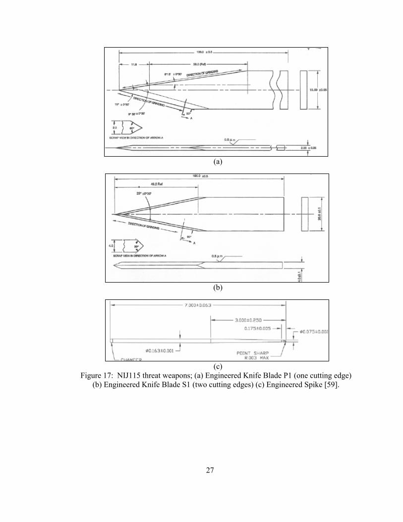
Figure 17: NIJ115 threat weapons; (a) Engineered Knife Blade P1 (one
cutting edge) (b) Engineered Knife Blade S1 (two cutting edges)
(c) Engineered Spike [59]. ...................................................................................... 27
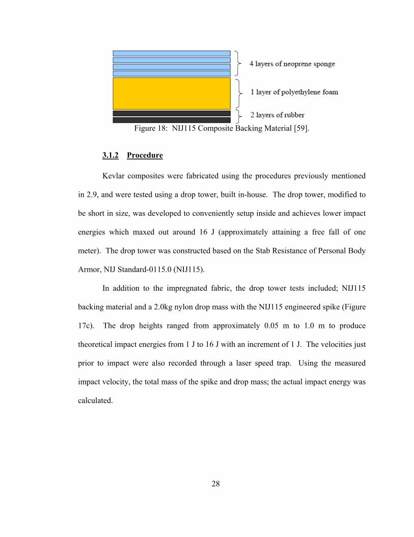
Figure 18: NIJ115 Composite Backing Material [59]. ..................................................... 28
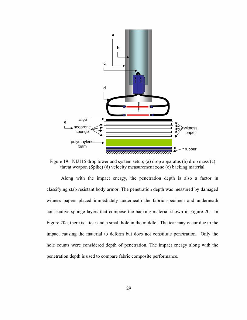
Figure 19: NIJ115 drop tower and system setup; (a) drop apparatus (b)
drop mass (c) threat weapon (Spike) (d) velocity measurement
zone (e) backing material ........................................................................................ 29
Figure 20: (a) Kevlar composite after impact at 16 Joules (b) impacted
witness paper at various impact energies (c) magnified view of the
impacted witness paper. .......................................................................................... 30
Figure 21: Different directions of the testing samples ..................................................... 32
Figure 22: Samples cut from fabric composites ............................................................... 32
Figure 23: A typical tension test in Zwick ....................................................................... 33
x
Figure 24: Flexibility test developed by Lee et Al [64] ................................................... 34
Figure 25: NIJ Spike test of STF based composites [63] ................................................. 36
Figure 26: NIJ Spike test of STF based composites with and without
PEG [65] ................................................................................................................. 38
Figure 27: NIJ Spike test of Kevlar based fabrics [65] .................................................... 40
Figure 28: Failure of the backing material after reaching higher energy
level during NIJ Spike test ...................................................................................... 41
Figure 29: NIJ Knife test graph ........................................................................................ 42
Figure 30: NIJ Spike test for various fabrics .................................................................... 44
Figure 31: NIJ Knife test for various fabrics .................................................................... 45
Figure 32: NIJ Spike test for determination of the best hybrid composite ....................... 48
Figure 33: NIJ Knife test for optimum determination ...................................................... 49
Figure 34: Knife/Spike performance for a 15 layers Kevlar/Spectra
Hybrid ..................................................................................................................... 51
Figure 35: Nanoparticles of CaCO3 .................................................................................. 53
Figure 36: NIJ Spike test of CaCO3 based composite ...................................................... 54
Figure 37: NIJ Knife test of CaCO3 based composite ...................................................... 55
Figure 38: Spike penetration in Spectra composite .......................................................... 57
Figure 39: Melted fibers in Spectra composite ................................................................. 58
Figure 40: Spike penetration in Kevlar composite ........................................................... 59
xi
Figure 41: Gluta reinforcement being torn up during spike penetration in
Kevlar composite .................................................................................................... 60
Figure 42: Breakage of the reinforcement between fibers during spike
penetration in Kevlar composite ............................................................................. 61
Figure 43: Knife penetration in Spectra composite .......................................................... 62
Figure 44: Zoom in the area where the cut is done by the blade in the
Spectra composite ................................................................................................... 63
Figure 45: Cut profile of one fiber in the Spectra composite ........................................... 64
Figure 46: Knife penetration in Kevlar composite ........................................................... 65
Figure 47: Yarn cut in Kevlar composite ......................................................................... 66
Figure 48: Fiber cut in Kevlar composite ......................................................................... 67
Figure 49: A thin coating of silated SiO2 with glutaraldehyde mixture on
the surface of the Kevlar fabric ............................................................................... 70
Figure 50: Silane-Silica-Gluta/Kevlar bonding ................................................................ 71
Figure 51: Coating of the silated SiO2 with glutaraldehyde onto the
surface of the Spectra fabric. ................................................................................... 72
Figure 52: Coating of the silated SiO2 with glutaraldehyde mixture
wearing off the surface of the Spectra fabric after impact. ..................................... 73
Figure 42: A thin coating of the silated SiO2 with glutaraldehyde
mixture on the surface of the Kevlar fabric ............................................................ 75

xii
Figure 43: Agglomerated Silated SiO2 particles and Glutaraldehyde
mixture. ................................................................................................................... 76
Figure 44: Neat Kevlar. .................................................................................................... 77
Figure 45: Silane-Silica-PEG/Kevlar bonding ................................................................. 78
Figure 46: Silane-Silica-Gluta/Kevlar bonding ................................................................ 78
Figure 47: Silane-Calcium Carbonate-Gluta/Kevlar ........................................................ 79
Figure 48: FTIR of the different glutaraldehyde ratios added to the
silated silica mixture. Gluta1=0.225g, Gluta2=0.113g,
Gluta3=0.45g .......................................................................................................... 80
Figure 49: FTIR of different glutaraldehyde combinations present in the
final mixture Silane-Silica-Gluta/Kevlar ................................................................ 81
Figure 50: Warp direction tension test ............................................................................. 82
Figure 51: Fill direction tension test ................................................................................. 83
Figure 52: 45° direction tension tests ............................................................................... 84
Figure 64: a)45degree Kevlar composite before test. b) after test. .................................. 87
Figure 65: a)45degree Spectra composite before test. b) after test. ................................. 89
Figure 53: Flexibility Set-up ............................................................................................ 90
Figure 54: Geometry models of the spike and nylon mass .............................................. 96
Figure 55: Cross-sections of spike and nylon mass .......................................................... 97
Figure 56: Geometry model of backing materials ............................................................ 97
xiii
Figure 57: Backing materials geometry details ................................................................ 98
Figure 58: The spike-mass system is placed on the top of the backing
material on aligned on the center ............................................................................ 99
Figure 59: Global view of the geometry ........................................................................... 99
Figure 60: SOLID92 element geometry. 3-D 10-Node Tetrahedral
Structural Solid. .................................................................................................... 101
Figure 61: Meshing of the target and backing material with SOLID92 ......................... 101
Figure 62: SOLID92 stress output .................................................................................. 102
Figure 63: SOLID186 geometry ..................................................................................... 103
Figure 64: Meshing of the Spike and its mass with elements SOLID186 ...................... 104
Figure 65: Insertion of contact element CONTA178 in between the
spike and the target ............................................................................................... 105
Figure 66: CONTA178 element geometry. .................................................................... 106
Figure 67: Warp and weft yarn orientations in global coordinate system. ..................... 107
Figure 68: Local orthogonal coordinate system for warp layer. .................................... 107
Figure 69: Boundary conditions applied on the system ................................................. 112
Figure 70: Simulated penetration of the spike. VonMises stress result. ........................ 113
Figure 71: Comparison graph of Simulated Quasi-static impact
penetration to Experimental .................................................................................. 114
xiv
LIST OF TABLES
Table 1: The amount of glutaraldehyde, water and silane used to
functionalize 5.5g of 30 nm silica particles according the
manufacturers procedure ......................................................................................... 24
Table 2: Results table for NIJ Knife data of 12 layers combination of
reinforced Correctional Kevlar and Spectra .......................................................... 126
Table 3: Results table for flexibility test on the different armor
composites ............................................................................................................... 90
Table 4: Material properties table for the different constituents of the
model ..................................................................................................................... 111
Table 5: Results table for NIJ Spike data of 12 layers of independent
fabric neat and composite ..................................................................................... 125
Table 6: Results table for NIJ Spike data of 12 layers combination of
reinforced Correctional Kevlar and Spectra .......................................................... 127
Table 7: Results table for NIJ Spike data of 12 layers combination of
reinforced Kevlar and Spectra ............................................................................... 128
Table 8: Results table for NIJ Spike data of 12 layers combination of
neat Correctional Kevlar and Spectra ................................................................... 129
xv
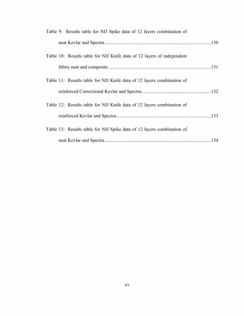
Table 9: Results table for NIJ Spike data of 12 layers combination of
neat Kevlar and Spectra ........................................................................................ 130
Table 10: Results table for NIJ Knife data of 12 layers of independent
fabric neat and composite ..................................................................................... 131
Table 11: Results table for NIJ Knife data of 12 layers combination of
reinforced Correctional Kevlar and Spectra .......................................................... 132
Table 12: Results table for NIJ Knife data of 12 layers combination of
reinforced Kevlar and Spectra ............................................................................... 133
Table 13: Results table for NIJ Spike data of 12 layers combination of
neat Kevlar and Spectra ........................................................................................ 134
1
CHAPTER 1.INTRODUCTION
Most of body protection gears for soldiers have been aimed towards ballistic
protection. Because ballistic protection mainly consists of rigid panels (i.e. ceramic
plates) inserted into a fabric pouch or incorporated in hard formed gear, they are
restricted to the head and torso. It does not include the extremities such as hands, arms,
necks, and legs. The head and torso are extremely important to protect because these
areas consist of life supporting organs. Due to increased casualties as a result of
extremity injuries and the increase in soldiers carry on loads, further development in
lightweight and flexible warrior systems has been explored. The need for lightweight
and flexible armor is to maximize the maneuverability without sacrificing protection of
the soldier. In addition to ballistic resistance, attention, is also given to threats imposed
by sharp weapons. Protection against both threat systems incorporating the desired
lightweight and flexible characteristics is under continual investigation.
A case in point is nanotechnology. This allows doing away with the bulky and
heavy plates and replacing that with a nano-materials system that can dissipate the
impact energy effectively. Development of nanocomposites by nanoparticle infusion
into polymers has been around for quite sometime. The benefit of nanoparticle infusion
comes from the fact that with a low particle loading results in a relatively large
improvement in chemical, thermal, and mechanical properties. In addition to the
improved properties, the weight of the composite is significantly reduced compared to
2
conventional method of reinforcement with large objects (i.e. ceramic plates). The
increase in properties and performance is due to the increase in surface energy, which is
caused by the relative increase in atoms at the surface, facilitating the interaction with
the surrounding polymers. The goal of nanoparticle infusion is to achieve an optimal
dispersion of nanoparticles into the matrix, and preferably a strong bonding between the
particle and the surrounding polymer. Uniform dispersion is necessary to improve Van
der Waals interaction between the particles and polymer and is imperative for
enhancing the strength of the resulting nanocomposites. One of the ways to improve
such bonding is to use a coupling agent between the organic and inorganic phases. In
this investigation, we have used organosilanes to modify the surfaces of Silica (SiO2)
nanoparticles. Organosilanes has the ability to incorporate both organic- and inorganic-
compatible functionality within the same molecule. In order to achieve even greater
performances, investigations have shown that stronger bonding links could be obtained
by incorporating another chemical belonging to the formaldehyde family. This
formaldehyde type chemical called Glutaraldehyde increases the number of bonding
between silated particles. Improved impact resistance compared to neat fabric and
current flexible armor material systems has been achieved.
1.1 Literature Review
Extensive experimental work has been done in recent years on flexible material
for body protection applications which are not limited to surgical gloves,
geotextiles/geomembranes and impact resistant composites. The literature review
includes methods and research on stab resistant [2-5] (i.e. puncture due to a knife and/or
3
spike), cut resistant and ballistic resistant materials and technology that has improved
these characteristics in common materials used for body protection (i.e. Kevlar).
Ngyen et al. [1] researched the mechanisms of puncture in thin rubber
membranes (i.e. protective gloves, neoprene, nitrile, and natural rubber) following
ASTM F1342 [2]. They used a conical probe with different cone angles and varied
diameters to derive expressions to calculate the theoretical puncture force versus the
varied probe geometry based on the deformation of the membrane. It was concluded
that the penetration force was not dependent on the probe geometry but related to an
intrinsic material parameter.
Leslie et al. [3] studied puncture resistance of a variety of medical glove
material that is specific to resisting needle punctures (i.e. finger guards, glove liners and
thicker latex gloves). The results included a quantitative measurement of peak force
and work required for a needle to puncture the material. These two values were used to
compare surgical hand protection systems.
Erlich et al. [4] studied the quasi-static penetration of both a blunt and sharp end
penetrator through a single ply of Zylon® fabric. They used quasi-static tests to
compare their previous work on dynamic behavior. They realized that failure modes are
the same but just at different levels for static versus dynamic testing. The test setup
captured video of the entire load stepping up to failure. This allowed a side by side
comparison of the measured data with the captured failure modes occurring during
penetration. They report that the deformation and the failure modes present are the
same between the quasi-static and ballistic test taking into account what was previously
mentioned.
4
Koerner et al. [5], Narejo et al. [6] and Wilson-Fahmy et al. [7] studied the
puncture resistance of geomembranes in three sections; theory, experimental and
examples, which were individually published. The works discuss the effects of
geomembranes used as liners underground or underwater. They simulate puncture from
gravel and soil by studying the geometry of the protrusion to the deformation of the
geomembrane and includes hydrostatic and geostatic pressures during the load. They
compare the thickness of the geomembranes and the addition of geotextiles and their
thickness to give increase puncture resistance to geomembranes and to give a cost
effective approach.
In complement to the series of works mentioned above Ghosh et al. [8]
concentrates on the puncture resistance of geotextiles and uses a test method similar to
ASTM D4833 [9], but includes the pre-straining of the material.
Lara et al. [10, 11] in 1996 studied glove material (neoprene and Kevlar) for the
cutting effects of degradation of blade sharpness, blade speed, sample holder as flat
versus semi-circular, and the load applied to the specimen. After testing, the results
concluded that changing of the blade is required for each test due to dulling of the
blade, the blade speed and sample holder had little effect on the results, and a series of
test are recommended to obtain the range of load which is specific to each material.
The later is in replace of applying the same load to different materials and measuring
the varied blade cycle. Comparing low to high cut resistant material, more blade cycles
are required for the later. This adds to the degradation of the blade and inaccurate
results. In 1997, ASTM approved standard F1790 [12] which is similar to that of Lara
et al except it restricts the blade travel and measures the load which is allowed to vary,

5
due to the setup, instead of keeping it constant. In 2000, Lara et al. [13] evaluated
methods and standards of EN 388, ASTM 1790 and ISO 13997 and compared them to
their previous works in 1996. They continue to emphasize the point to use a constant
normal force to be applied to the fabric specimen that is to be cut. The faults of the
three standards were found to be optimal for different specimen thicknesses and the
results depended greatly on the coefficient of friction and hence are incomparable. Shin
et al. [14] developed a method and apparatus to measure cut resistance of yarn,
specifically tested Zylon®, under tension. His results are more detailed to include
visuals and quantitative results to analyze yarn failure modes. With their interest in
fragment impact, they also test at different slice angles. These methods and standards
are limited to cut resistance and do not include any other failure modes such as
puncture, but give an approach to critical thinking when comparing methods for testing
flexible protective materials.
An approach to spike impact has been developed in England, with the:NIJ
Standard 0115.00 [66]. This standard specifies the minimum performance requirements
for body armor that is resistant to attack by typical pointed and edged weapons; and it
describes the test methodology to be used for this assessment. The spike, or knife, is
held by a mass and dropped at various heights. A backing material supports the target
and is constituted with four neoprene layers, one polyethylene layer and two rubber
layers. Knowing the areal density of the target, it is then possible to calculate the energy
and normalized energy at impact. This allows the comparison and ranking of the
different personal body protections manufactured and put to the test.
6
Works from MIT by Deshmukh and McKinley [15] include the study of a liquid
infused fabric body armor which resists impact when under a magnetic field. This fluid
is called magnetorheological (MR) fluid which consists of iron particles. Works by
Gadow et al. [16] studied the stab resistance of a thermally sprayed ceramic and cermet
coatings on aramid fabrics, such as Twaron. The heated coating is sprayed onto the
fabric using an atmospheric plasma spray torch and is cooled at the point of contact
with the fabric to prevent fiber damage. The coating is 50 to 100 μm thick with
individual particles sizes of 10-22 μm. The coatings from the particles tend to have a
high density. This may give a more flexible and lightweight solution to the common
ceramic reinforced body armor, but the weight is still relatively high. Other coatings
have been explored using a shear thickening fluid, commonly known as a dilatant fluid,
which is impregnated into woven aramid fabrics. The rheology of the non-Newtonian
fluid behavior has been studied by Raghavan et al. [17, 18], Maranzano et al. [19] and
Lee et al. [20]. These works discuss the effects of the fluid’s increase in viscosity when
there is an increase in shear rate. The increase in fluid’s viscosity is the key in energy
dissipation of impacts (i.e. ballistic). More works of Lee et al. [21, 22], Wetzel et al.
[23], Egres et al. [24, 25] and Tan et al. [26] have studied the performance of the silica
infused fabrics. These three groups have mainly worked with Shear Thickening Fluid
(STF) which involves a centrifugation and exchange processes to transform a silica and
polyethylene glycol (PEG) mixture into STF. The development of shear thickening
fluid (STF) begins with micron size silica suspended in water. This material is made
into STF through centrifugation and exchange processes. In other approaches
polyethylene glycol (PEG) is added in incremental quantity to the silica suspension and

7
water is removed through evaporation. The process is repeated until the admixture
reaches the desired ratio of 55:45 for silica and PEG by weight. STF developed in this
manner is dissolved in ethanol and impregnated into Kevlar fabric and then dried to
remove ethanol. The resulting composite is Kevlar impregnated with a mixture of PEG
and silica. These studies report the ballistic performances of composite materials
composed of Kevlar fabric impregnated with a colloidal shear thickening fluid (micron
size silica particles dispersed in ethylene glycol). The impregnated Kevlar fabric yields
a flexible, yet penetration resistant composite material. Ballistic and stab penetration
measurements have demonstrated a significant improvement due to the addition of
shear thickening fluid to the fabric without any loss in material flexibility. Such
enhancement in the performance has been attributed to the increase in the yarn pullout
force upon transition of the STF to its rigid state during impact. Furthermore, STF
impregnated Kevlar has vastly superior stab resistance in addition to flexible ballistic
protection. While these preliminary studies establish clearly the viability of the
STF/fabric composite as a future flexible body armor system, the entire scope of
particle-polymer interaction along with the complexities associated with fabric
impregnation must still be addressed before an optimal, lightweight STF/fabric system
can be developed.
To evaluate the results, theoretical work has also been carried through. Works
on modeling ballistic impacts on fibrous materials, even force profiles of sewing
needles, and modeling sharp indenters on metals have been looked into.
The works of Phoenix et al. [27], Porwall et al. [28], and Taylor et al. [29] investigate
ballistic impacts on integral armor and fibrous composites. The ballistic studies focus
8
on the wave that occurs from the impact and temperature effects and yarn pullout. The
above works do not study impacts at low velocity where wave propagation and
temperature effects do not occur. Gu [30] didn’t consider the projectile geometry during
ballistic impact of plain-woven fabric, while it is believed that geometry of the
projectile plays an important role in penetration mechanics. Works of Luo et al. [31]
consider the fabric composite to be homogeneous orthotropic material comprised of
wavy fibers. Common among the above studies, deformation analysis is of great
importance in ballistic impact. In the present work of this thesis, the impact velocity is
below the ballistic range, and the projectile (in the case of the spike) is not a fragment
simulated projectile (FSP).
Stylios et al. [32] focused on the profile of a sewing needle point affecting the
penetration force. This work aims to optimize the profile to reduce the force of
penetration. The works of Suresh et al. [33, 34], Giannakopoulos et al. [35] and
Andrews et al. [36] from the mid nineties to 2001 were the most inspiring. Their work
focused on the analysis of sharp indenter impacts into rate dependent metals. The
motion of the indenter is described by Newton’s second law, considering the indenter
mass, the motion of the indenter and the impact force. Once the equation of motion and
the governing equation are formulated, it is solved with appropriate boundary
conditions to find the maximum depth of penetration. Penetration of an indenter
described in these references is similar to the penetration of a sharp spike considered in
our studies. Accordingly we have developed a numerical model using the finite element
method to simulate the motion of the indenter penetrating through the fabric.
9
1.2 Scope of Thesis
The current study is mainly focused on the enhancement in non-penetration
resistance. The STF/Kevlar composite previously developed, was only able to hold a
zero-penetration up to 11J-cm2/g. It is seen that the use of nanoscale silica particles
mixed with PEG does not fulfill the desired results expected in Shear Thickening
theories. Moreover the use of PEG does not allow the creation of good bonds between
the silica particles and the Kevlar fibers. It has consequently become crucial to find a
new way to improve the resistance to spike impacts.
The study of each component used before to manufacture the STF/Kevlar composite has
revealed that the inclusion of a Silane coupling agent would help increasing the bonds
between the silica particles and the polymer. However, despite an increase in
performance by the addition of the silane, it was observed that modestly higher level of
performance could be achieved. Therefore, by removing the PEG out of the equation of
the mixture, the new composite showed again an increase of performance.
It has then become clear that the use of nanoscale particles along with high bonding
ability chemicals was the way which would lead the resistance performance to a higher
level. Indeed the experiments show that by increasing the bonding between particles
and the Kevlar fibers, the performances in energy dissipation during spike impact has
significantly increased.
In order to achieve higher bonding performances, a new chemical has been
introduced into the mixture. The glutaraldehyde, a type of formaldehyde, creates strong
covalent bonds between the amino groups that cover the surface of the silica
nanoparticles. These amino groups are brought into the system by the addition of silane
10
into the mixture. By increasing the amount of bonds between the particles, the energy
dissipated will increase providing a good resistance to the composite.
By performing a Finite Element Model with ANSYS®, a predictive tool can be
used to determine the depth of penetration when NIJ Spike Tests are performed. It will
also indicate the amount of energy received during impact. This represents an important
tool in composite design as it allows the user to simulate any spike impact knowing the
material properties. This will also help in reducing the number of experiments.
In view of the discussion, it is therefore seen that a system of nanoparticle scale
silica dispersed ultrasonically into a mixture of silane and glutaraldehyde, and then
impregnated with ballistic grade fabric, such as Kevlar and Spectra constitute a
materials system which should be equivalent or better than the currently used PEG
based fabric composites for flexible body armor protection.

11
CHAPTER 2.MATERIALS, EQUIPMENT AND SYNTHESIS
2.1 KM-2 Kevlar® Fabric
The organic fiber was originally developed by DuPont in 1965 for steel belting
in vehicle tires [49]. In the early 1970’s it was considered to be a ballistic grade fabric
after NIJ tests revealed its ballistic resistant potential. This breakthrough started the
interest in new age flexible body armor based on its lightweight and high strength
characteristics. Multiple grades and styles are available and other companies have
produced similar textiles to Kevlar® such as, Twaron®, Spectra®, Zylon® and more
[51].
The Kevlar used in the current investigation is from JPS Composite Materials,
former textile manufacturing branch of Hexcel Schwebel. It is a plain-woven style 706,
also known as Kevlar KM-2 (600 denier). It is a ballistic grade, high performance
textile with an areal density of 180 g/m2 and fabric thickness of 0.23 mm. The
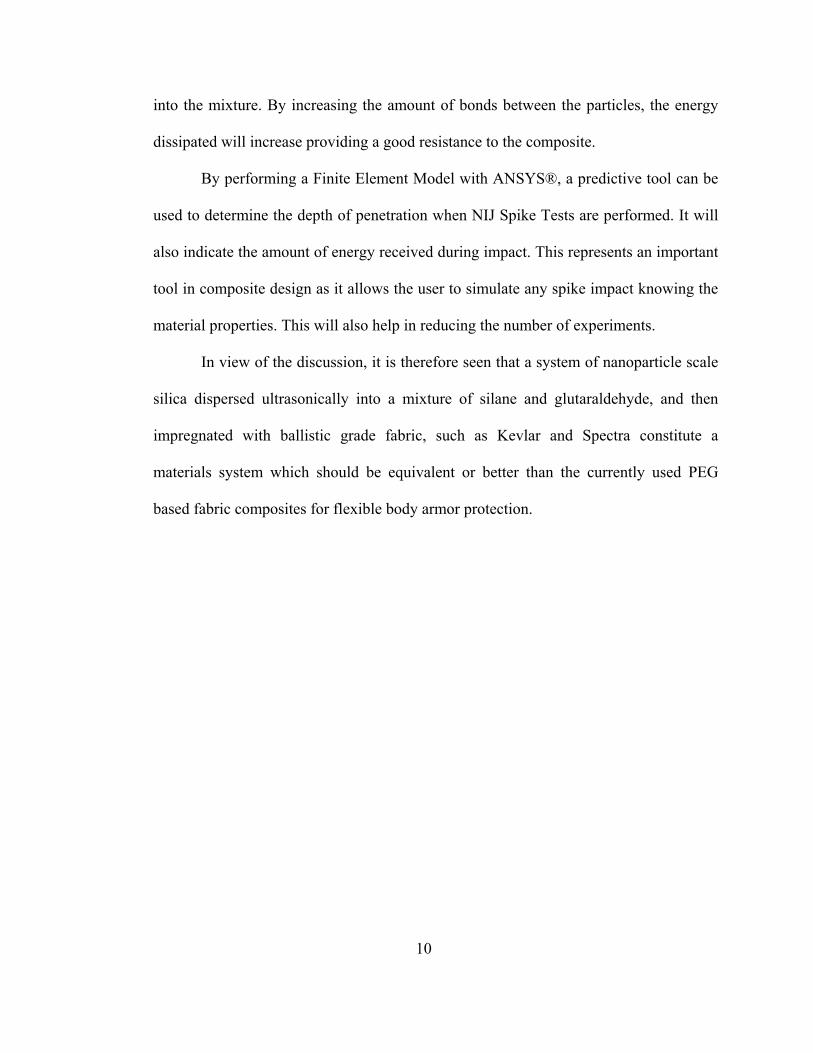
molecular structure of Kevlar, shown in Figure 1, contains a repeating unit of an amide
group and an aromatic ring. These molecular chains, making the polymer structure, are
further connected by hydrogen bonds. The two groups that makeup the repeating units
align parallel to the length of the fiber during the extrusion process and orientate
radially in a spoke like manner, shown in Figure 2. The regularity of the molecular
structure is what is responsible for its impact strength.
12
Figure 1: (a) Molecular structure of Kevlar (b) aromatic ring (c) amide group.
Figure 2: A x-ray linear dichroism microscopic view of the cross section of a Kevlar
fiber showing radial symmetry [52, 53].
2.2 Correctional Kevlar®
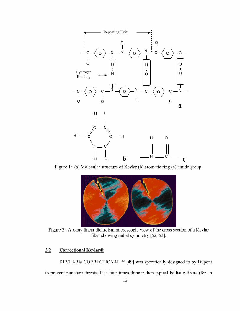
KEVLAR® CORRECTIONAL™ [49] was specifically designed to by Dupont
to prevent puncture threats. It is four times thinner than typical ballistic fibers (for an
O C
H
N
H : O
O : H
C
H
O
O
N
O
C O C
O : H
O C N C O
O
N C O C
O O
N
Hydrogen Bonding
Repeating Unit
N C
H O
C C
C C
C C
H H
H H
H H H
13
ultradense weave) and five times stronger than steel on an equal weight basis. As
explained by Dupont the fabric is woven so tightly together, that when struck by sharp
objects, such as spikes, awls or shanks, the fiber absorbs and dissipates the energy of the
puncture or penetration.
Figure 3: Kevlar Correctional fabric under NIJ Spike test. [49]
With similar chemical properties as KM-2 Kevlar®, the Correctional Kevlar®
stands out due to its lightweight characteristic.

14
2.3 Spectra®
Figure 4: Spectra fibers are made out bright white polyethylene
Spectra® fiber, developed by Honeywell [51], is one of the world's strongest
and lightest fibers. A bright white polyethylene, it is, pound-for-pound, fifteen times
stronger than steel, more durable than polyester and has a specific strength that is 40
percent greater than aramid fiber. Spectra® fiber is produced from ultrahigh molecular
weight polyethylene (UHMWPE) using a patented gel-spinning process. UHMWPE is a
remarkably durable plastic, and scientists at Honeywell have captured the tremendous
natural strength in the molecular backbone of this everyday plastic to create one of the
world's strongest and lightest fibers. The gel-spinning process and subsequent drawing
steps allow Spectra® fiber to have a much higher melting temperature (150°C or 300°F)
than standard polyethylene. With outstanding toughness and extraordinary visco-elastic
properties, Spectra® fiber can withstand high-load strain-rate velocities. Light enough
to float; it also exhibits high resistance to chemicals, water, and ultraviolet light. It has
excellent vibration damping, flex fatigue and internal fiber-friction characteristics, and
15
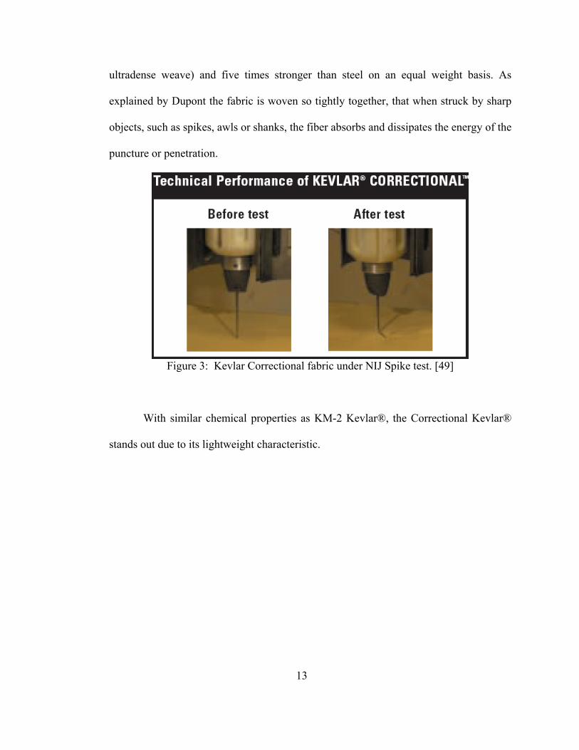
Spectra® fiber's low dielectric constant makes it virtually transparent to radar. Spectra®
fiber is used in numerous high-performance applications, including police and military
ballistic-resistant vests, helmets and armored vehicles, as well as sailcloth, fishing lines,
marine cordage, lifting slings, and cut-resistant gloves and apparel.
Figure 5: Molecular structure for Ultra high molecular weight polyethylene (UHMWPE).
Ultra high molecular weight polyethylene (UHMWPE) is a type of polyolefin,
and, despite relatively weak Van der Waals bonds between its molecules, derives ample
strength from the length of each individual molecule. It is made up of extremely long
chains of polyethylene, which all align in the same direction. Each chain is bonded to
the others with so many Van der Waals bonds that the whole can support great tensile
loads. The yield strength are as high as 2.4 GPa and density as low as 0.97 kg/l
When formed to fibers, the polymer chains can attain a parallel orientation greater than
95% and a level of crystallinity of up to 85%. In contrast, Kevlar derives its strength
from strong bonding between relatively short molecules

16
2.4 Polyethylene Glycol (PEG)
Polyethylene Glycol (PEG) is a water soluble condensation polymer of ethylene
oxide and water with a molecular structure given in Figure 6. The viscosity and melting
temperature increase (although melting temperatures are in the negative Celsius
temperature range) as the molecular weight increases [23, 54]. The current work uses a
low average molecular weight of 200g/mol with a density of 1.1239 g/mL.
Figure 6: Molecular formula for PEG where n denotes the molecular weight. For the current research n=4.2 corresponds to a 200g/mol average molecular weight.
Rheology research of PEG at varied molecular weight and mixed with varied
particle size, shape, type and weight percent [19, 23] has been compiled. Much of the
PEG and particle mixture research is that of Wetzel et al. [23] and the molecular weight
of choice is 200 g/mol. Wetzel et al. showed that when mixed with micron colloidal
silica particles the fluid transitioned from a shear thinning fluid at low shear rates to a
shear thickening fluid at high rates. PEG is used to couple the molecules of the silica
particles to produce non-ionic surfactants and bond to the Kevlar® fabric.
2.5 Silica Nanoparticles
30nm diameter silica particles from Sigma-Aldrich are used in the composite
fabric to give resistance against sharp impactors. They have a surface area in between
140 and 180 m2/g and a density of about 2.2 – 2.6 g/ml [55]. They are prepared using
the chemical vapor deposition (CVD) method utilizing either the plasma enhanced
method or the laser induced method [67]. The synthesis of nanostructured material by
HO – (CH2 – CH2 – O)n – H
17
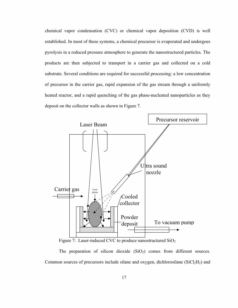
chemical vapor condensation (CVC) or chemical vapor deposition (CVD) is well
established. In most of these systems, a chemical precursor is evaporated and undergoes
pyrolysis in a reduced pressure atmosphere to generate the nanostructured particles. The
products are then subjected to transport in a carrier gas and collected on a cold
substrate. Several conditions are required for successful processing: a low concentration
of precursor in the carrier gas, rapid expansion of the gas stream through a uniformly
heated reactor, and a rapid quenching of the gas phase-nucleated nanoparticles as they
deposit on the collector walls as shown in Figure 7.
Figure 7: Laser-induced CVC to produce nanostructured SiO2
The preparation of silicon dioxide (SiO2) comes from different sources.
Common sources of precursors include silane and oxygen, dichlorosilane (SiCl2H2) and
Precursor reservoirLaser Beam
Ultra sound nozzle
Laser plume
Cooled collector
Powder deposit To vacuum pump
Carrier gas
18
nitrous oxide (N2O), or tetraethylorthosilicate (TEOS; Si(OC2H5)4). The reactions are as
follows:
SiH4 + O2 → SiO2 + 2H2
SiCl2H2 + 2N2O → SiO2 + 2N2 + 2HCl
Si(OC2H5)4 → SiO2 + byproducts
Those reactions all have advantages and disadvantages in terms of additional
residues but the results produce similar SiO2 nanoparticles which are used into the
mixture.
2.6 Organosilane
In an attempt to further improve the penetration resistances of the composite,
silica particles were functionalized with a silane coupling agent. Such functionalization
was first tested with extruded Nylon 6 filaments in another research project [63]. This
resulted in a significant gain in Young’s Modulus and the Tensile Strength of the
filaments [38, 56]. Such improvements have been confirmed for stab impacts in the
early stage of this project [63]. The terms silated, functionalized and modified particles
will be used through out the text. The three terms are interchangeable and refer to the
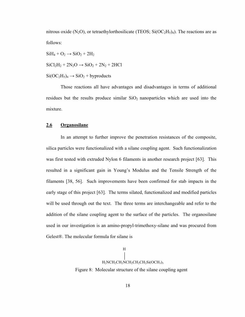
addition of the silane coupling agent to the surface of the particles. The organosilane
used in our investigation is an amino-propyl-trimethoxy-silane and was procured from
Gelest®. The molecular formula for silane is
Figure 8: Molecular structure of the silane coupling agent
H
H2NCH2CH2NCH2CH2CH2Si(OCH3)3

19
We have used silane coupling agent to form durable bonds between inorganic
and organic materials, such as the silica nanoparticles and a polymer. The silane used in
our study was extremely effective with silica particles [57]. Molecular structure of
silane is shown below as it forms chemical bonds between the particles and the
polymer.
32 )( XSiCHR n −−−
Figure 9: Molecular structure of the trialkoxysilane coupling agent
Figure 10: Silanol linkages between the polymer and the silica substrate [57].
2.7 Glutaraldehyde
In addition to the organosilane, substances such as glutaraldehyde further
promote bonding between silated silica particles. The glutaraldehyde has been procured
from JT Baker® (222 Red School Lane Phillipsburg NJ 08865 U.S.A.). Our interests in
this chemical are in its property to create strong covalent bonds that bridges one silated
silica particles to another.
Organofunctional Linker Silicon
A Hydrolyzable Groups
20
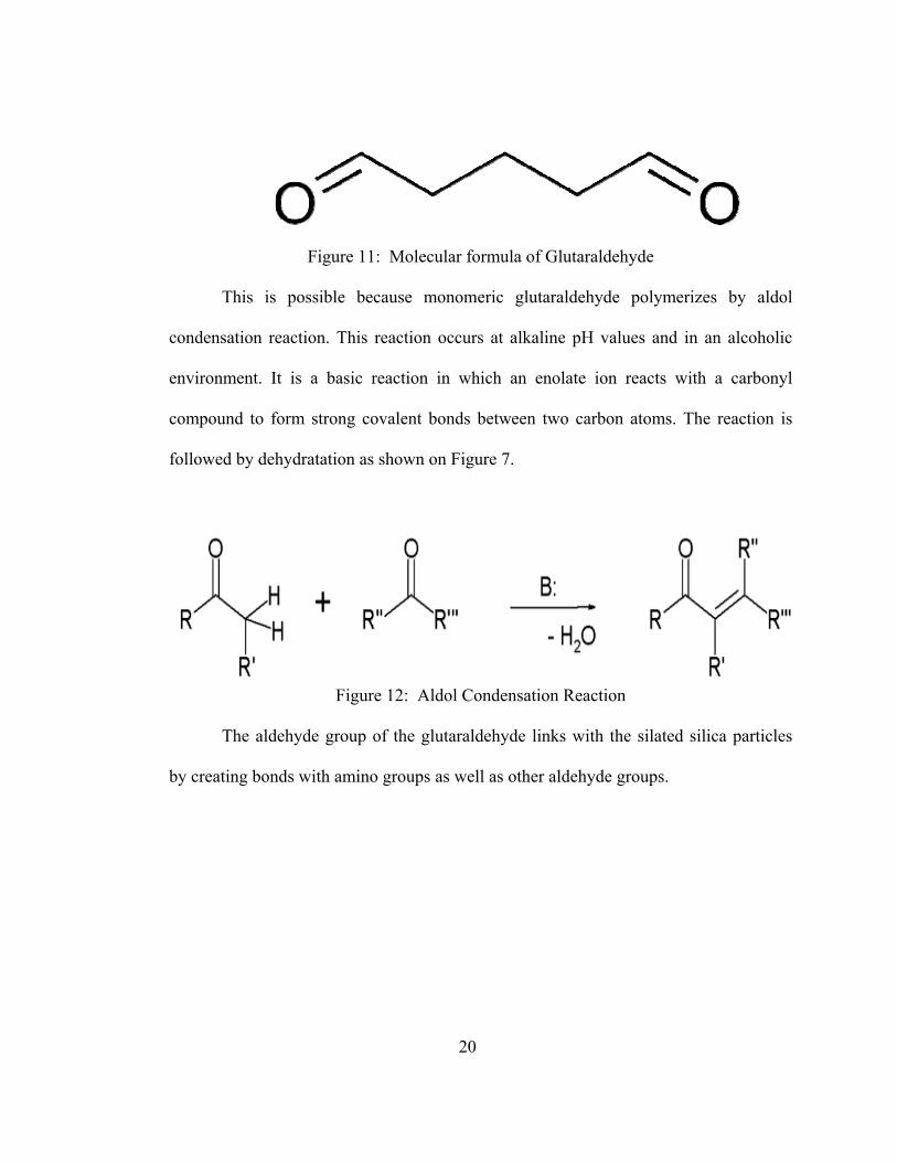
Figure 11: Molecular formula of Glutaraldehyde
This is possible because monomeric glutaraldehyde polymerizes by aldol
condensation reaction. This reaction occurs at alkaline pH values and in an alcoholic
environment. It is a basic reaction in which an enolate ion reacts with a carbonyl
compound to form strong covalent bonds between two carbon atoms. The reaction is
followed by dehydratation as shown on Figure 7.
Figure 12: Aldol Condensation Reaction
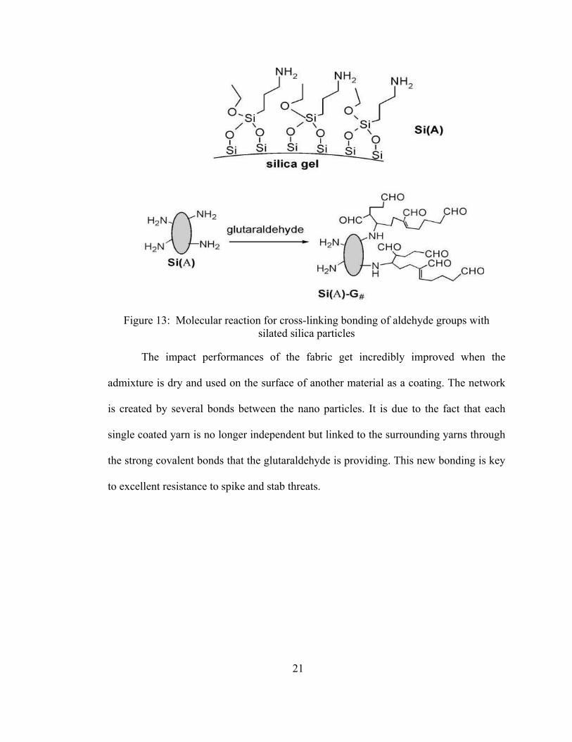
The aldehyde group of the glutaraldehyde links with the silated silica particles
by creating bonds with amino groups as well as other aldehyde groups.
21
Figure 13: Molecular reaction for cross-linking bonding of aldehyde groups with silated silica particles
The impact performances of the fabric get incredibly improved when the
admixture is dry and used on the surface of another material as a coating. The network
is created by several bonds between the nano particles. It is due to the fact that each
single coated yarn is no longer independent but linked to the surrounding yarns through
the strong covalent bonds that the glutaraldehyde is providing. This new bonding is key
to excellent resistance to spike and stab threats.
22
2.8 High Intensity Ultrasonic Liquid Processor
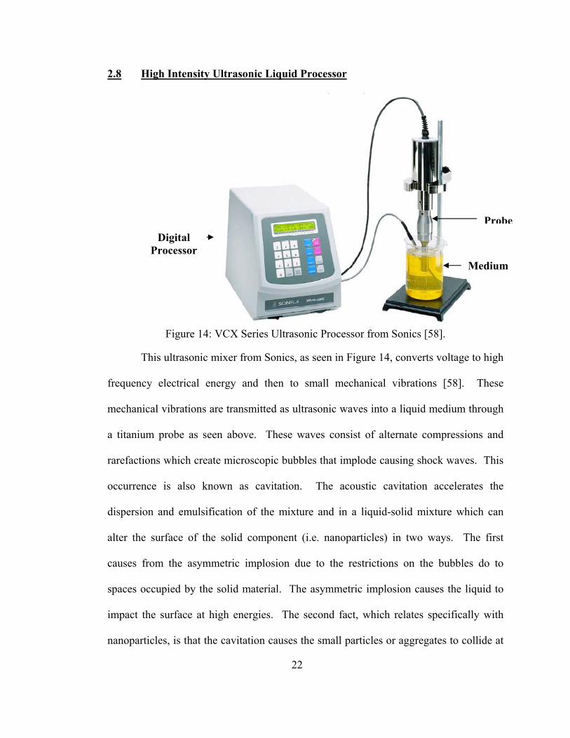
Figure 14: VCX Series Ultrasonic Processor from Sonics [58].
This ultrasonic mixer from Sonics, as seen in Figure 14, converts voltage to high
frequency electrical energy and then to small mechanical vibrations [58]. These
mechanical vibrations are transmitted as ultrasonic waves into a liquid medium through
a titanium probe as seen above. These waves consist of alternate compressions and
rarefactions which create microscopic bubbles that implode causing shock waves. This
occurrence is also known as cavitation. The acoustic cavitation accelerates the
dispersion and emulsification of the mixture and in a liquid-solid mixture which can
alter the surface of the solid component (i.e. nanoparticles) in two ways. The first
causes from the asymmetric implosion due to the restrictions on the bubbles do to
spaces occupied by the solid material. The asymmetric implosion causes the liquid to
impact the surface at high energies. The second fact, which relates specifically with
nanoparticles, is that the cavitation causes the small particles or aggregates to collide at
Digital Processor
Medium
Probe

23
high speeds. Both of these cases erode and expose new surfaces to react further with
the surrounding medium.
2.9 Synthesis of the Silated-Nanoparticles-Glutaraldehyde -Fabric Composites
Actual fabrication procedures, shown in Figure 15, include the silica
nanoparticles dispersed, by sonication, directly into a mixture of Water, Silane and
Glutaraldehyde such that the ratio of water:silica:silane:gluta is about 24:22:10:1 by
weight. The modification of the silica nanoparticles with the use of silane is followed
according to the manufacturer’s procedures and is derived from the surface area of the
nanoparticles. Based on the fact that one gram of silane covers a surface area of 358
m2, silane was added to a 95% ethanol – 5% water mixture to yield a 2% final
concentration of silane. The actual amount of each chemical used is listed in Table 1.
After adding ethanol, the solution is homogenized with a high speed mechanical mixer
which will grind and break up major agglomerates. This 30 minutes step helps in
obtaining a uniform mixture which will be ready for the next step. The addition of
ethanol as a medium aides in the dispersion during sonication to breakup the silica
agglomerations as discussed in section 2.5. After sonication for about three hours, the
mixture was used to soak 12 layers of Kevlar fabric cut in dimensions of 30.48 cm x
30.48 cm (12 in x 12 in). To impregnate the fabric, the layers were placed in a sealed
plastic bag along with the sonicated mixture. The fabric was then let to rest for about
24 hours. Afterward, the fabric layer was placed in the furnace and heated at 110°C
until they were dry, i.e. all the ethanol had evaporated. The 12 layers of Kevlar
impregnated with the silica-silane-glutaraldehyde mixture resulted in an areal density of
24
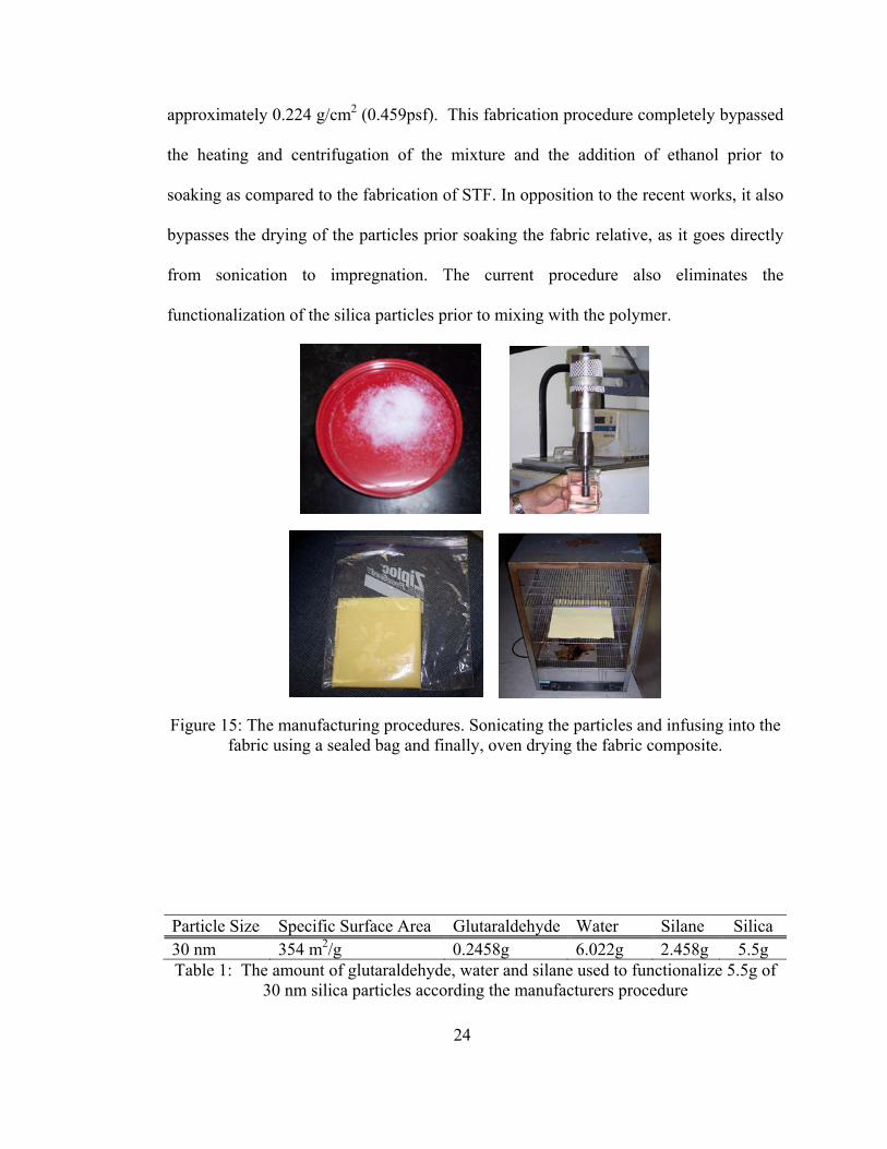
approximately 0.224 g/cm2 (0.459psf). This fabrication procedure completely bypassed
the heating and centrifugation of the mixture and the addition of ethanol prior to
soaking as compared to the fabrication of STF. In opposition to the recent works, it also
bypasses the drying of the particles prior soaking the fabric relative, as it goes directly
from sonication to impregnation. The current procedure also eliminates the
functionalization of the silica particles prior to mixing with the polymer.
Figure 15: The manufacturing procedures. Sonicating the particles and infusing into the fabric using a sealed bag and finally, oven drying the fabric composite.
Particle Size Specific Surface Area Glutaraldehyde Water Silane Silica 30 nm 354 m2/g 0.2458g 6.022g 2.458g 5.5g Table 1: The amount of glutaraldehyde, water and silane used to functionalize 5.5g of
30 nm silica particles according the manufacturers procedure
25
CHAPTER 3.EXPERIMENTATION
3.1 NIJ Stab Test
The National Institute of Justice (NIJ) was established in 1968 [51]. NIJ
introduced its first standard for body armor performance, NIJ 0101.00 (NIJ101), in
1972, during a trend of increased homicide cases for law enforcement officers. The
publication of NIJ101 occurred during an initial breakthrough of a whim testing of
DuPont’s Kevlar® fabric, which was initially developed in 1965 to replace steel belting
in vehicle tires. It is not until 1976 that an improved Kevlar fabric was concluded to be
an effective ballistic material. This was the result of several tests conducted on the
effects of blunt trauma, comfort and psychological effects (i.e. officer’s confidence in
safety during a threatening situation). They have collaborated with Office of law
Enforcement Standards (OLES), National Law Enforcement and Correction
Technology Center (NLECTC), the U.S. Secret Service and the Police Scientific
Development Branch (PSDB) in the United Kingdom (UK) to develop this standard.
Just recently, in September 2000, NIJ introduced the NIJ Standard 0115.0 (NIJ115) for
stab and puncture resistant body armor. It gives the minimum performance
requirements for body armor to resist a sharp weapon [59]. The focus of the current
research is stab resistance which follows NIJ115. It quantifies three levels of protection
based on the impact energy, in Joules. The levels range from low-level to high-level
protection ranging in measurable impact energies of 24 joules to 43 joules of energy.
26
3.1.1 Test Methodology
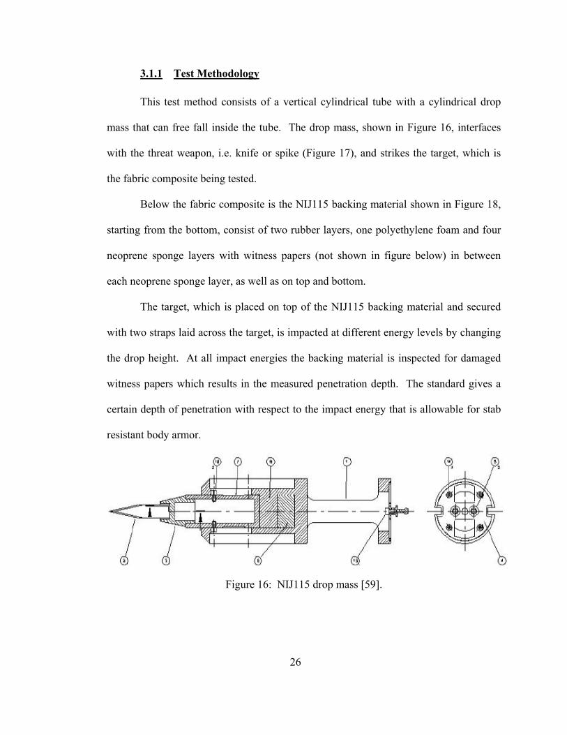
This test method consists of a vertical cylindrical tube with a cylindrical drop
mass that can free fall inside the tube. The drop mass, shown in Figure 16, interfaces
with the threat weapon, i.e. knife or spike (Figure 17), and strikes the target, which is
the fabric composite being tested.
Below the fabric composite is the NIJ115 backing material shown in Figure 18,
starting from the bottom, consist of two rubber layers, one polyethylene foam and four
neoprene sponge layers with witness papers (not shown in figure below) in between
each neoprene sponge layer, as well as on top and bottom.
The target, which is placed on top of the NIJ115 backing material and secured
with two straps laid across the target, is impacted at different energy levels by changing
the drop height. At all impact energies the backing material is inspected for damaged
witness papers which results in the measured penetration depth. The standard gives a
certain depth of penetration with respect to the impact energy that is allowable for stab
resistant body armor.
Figure 16: NIJ115 drop mass [59].
27
(a)
(b)
(c)
Figure 17: NIJ115 threat weapons; (a) Engineered Knife Blade P1 (one cutting edge) (b) Engineered Knife Blade S1 (two cutting edges) (c) Engineered Spike [59].
28
Figure 18: NIJ115 Composite Backing Material [59].
3.1.2 Procedure
Kevlar composites were fabricated using the procedures previously mentioned
in 2.9, and were tested using a drop tower, built in-house. The drop tower, modified to
be short in size, was developed to conveniently setup inside and achieves lower impact
energies which maxed out around 16 J (approximately attaining a free fall of one
meter). The drop tower was constructed based on the Stab Resistance of Personal Body
Armor, NIJ Standard-0115.0 (NIJ115).
In addition to the impregnated fabric, the drop tower tests included; NIJ115
backing material and a 2.0kg nylon drop mass with the NIJ115 engineered spike (Figure
17c). The drop heights ranged from approximately 0.05 m to 1.0 m to produce
theoretical impact energies from 1 J to 16 J with an increment of 1 J. The velocities just
prior to impact were also recorded through a laser speed trap. Using the measured
impact velocity, the total mass of the spike and drop mass; the actual impact energy was
calculated.
29
Figure 19: NIJ115 drop tower and system setup; (a) drop apparatus (b) drop mass (c) threat weapon (Spike) (d) velocity measurement zone (e) backing material
Along with the impact energy, the penetration depth is also a factor in
classifying stab resistant body armor. The penetration depth was measured by damaged
witness papers placed immediately underneath the fabric specimen and underneath
consecutive sponge layers that compose the backing material shown in Figure 20. In
Figure 20c, there is a tear and a small hole in the middle. The tear may occur due to the
impact causing the material to deform but does not constitute penetration. Only the
hole counts were considered depth of penetration. The impact energy along with the
penetration depth is used to compare fabric composite performance.
target
witness paper
neoprene sponge
polyethylene foam
rubber
a
b
c
d
e

30
(a) (b) (c)
Figure 20: (a) Kevlar composite after impact at 16 Joules (b) impacted witness paper at various impact energies (c) magnified view of the impacted witness paper.
3.2 Scanning Electron Microscope (SEM)
The improved performance of the Kevlar® composite is attributed to the
infusion of the silated silica and glutaraldehyde mixture coating the fabric. The
distribution over the fabric as well as covering the surface area of the tows can only be
seen by viewing it at a microscopic level. In addition to the distribution of particles, it
is important to see the agglomerations that are expected to occur when dispersing the
silica nanoparticles into the Ethanol. Although the clusters will occur naturally, the
objective is to still maintain uniform dispersion as much as possible. To observe these
features, a Field Emission Scanning Electron Microscope (FESEM) JEOL JSF-6330F
was used. In addition to the coating, the FESEM makes it possible to observe the impact
damage of the fabric composite. The samples were fixed to the stage with copper tape
and were coated with gold. The gold coating prevented charge build-up by the
electrons absorbed by the specimen. It gives the non-conductive specimen electrical
conductivity to reduce the ability to attain an electrostatic charge. This enabled the use
of a higher voltage to increase magnification.
tear
hole
31
3.3 Fourier Transform Infrared Spectroscopy (FTIR)
The Fourier Transform Infrared Spectroscopy uses the infrared spectrum formed
by the absorption of electromagnetic radiation at frequencies that associate to the
vibration of particular groups of chemical bonds from a molecule [60]. FTIR spectrum
versus wavelength absorption presents peaks referring to higher absorption of light
energy necessary for excitation. At these specific wave-numbers, the types of
functional bonds occurring in the specimen are indicated, giving rise to its molecular
structure or the so-called fingerprint [60]. The functional groups assist in the
understanding the stability and chemical bond characteristics in each type of bonds.
The samples were analyzed in powdered form.
3.4 Mechanical Testing
In order to have a better understanding and overview of the performance of
various composites, more specific tests were performed. Mechanical tests based on
tension were conducted in three different configurations. Those configurations depend
on the fabric architecture: the direction along the roll which folds when unrolling the
fabric is called warp and the orthogonal direction in which the yarns are sewed in
between the previous ones is called fill.
Finally a tension test at 45° to the yarn configuration was conducted to measure
the in-plane shear strength.
3.4.1 Testing procedure
32
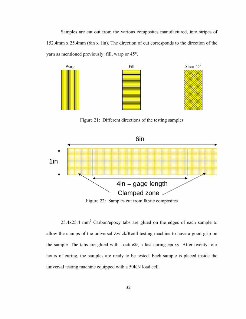
Samples are cut out from the various composites manufactured, into stripes of
152.4mm x 25.4mm (6in x 1in). The direction of cut corresponds to the direction of the
yarn as mentioned previously: fill, warp or 45°.
Figure 21: Different directions of the testing samples
Figure 22: Samples cut from fabric composites
25.4x25.4 mm2 Carbon/epoxy tabs are glued on the edges of each sample to
allow the clamps of the universal Zwick/Roëll testing machine to have a good grip on
the sample. The tabs are glued with Loctite®, a fast curing epoxy. After twenty four
hours of curing, the samples are ready to be tested. Each sample is placed inside the
universal testing machine equipped with a 50KN load cell.
1in
6in
4in = gage length Clamped zone
Warp Fill Shear 45˚
33
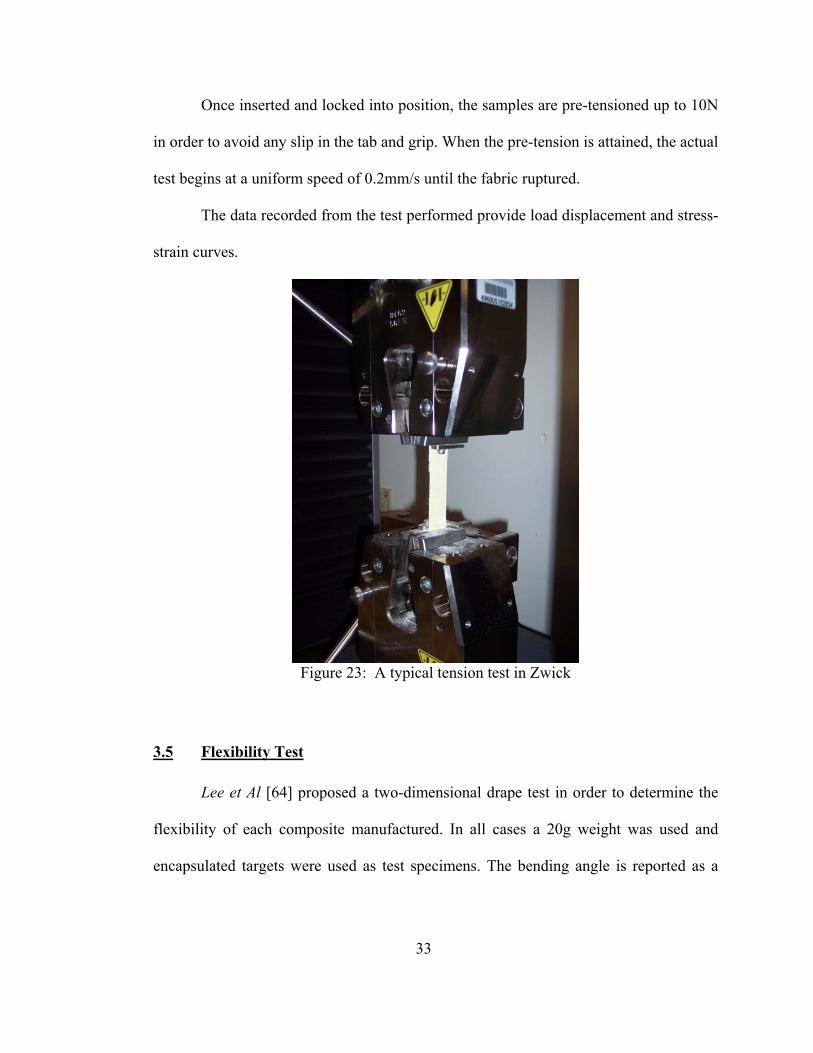
Once inserted and locked into position, the samples are pre-tensioned up to 10N
in order to avoid any slip in the tab and grip. When the pre-tension is attained, the actual
test begins at a uniform speed of 0.2mm/s until the fabric ruptured.
The data recorded from the test performed provide load displacement and stress-
strain curves.
Figure 23: A typical tension test in Zwick
3.5 Flexibility Test
Lee et Al [64] proposed a two-dimensional drape test in order to determine the
flexibility of each composite manufactured. In all cases a 20g weight was used and
encapsulated targets were used as test specimens. The bending angle is reported as a

34
measure of the target flexibility, with larger indicating greater flexibility. The target
thickness at the center of the composite is also measured with a micrometer.
Various composites used in this study were tested to ensure that the composites
developed keep its flexibility throughout the process.
Figure 24: Flexibility test developed by Lee et Al [64]
13.9 cm 1.3 cm
α
Aluminium mass ~20g
Composite

35
CHAPTER 4.RESULTS & DISCUSSION
4.1 Introduction
4.1.1 Functionalized Silica with PEG
Traditionally shear thickening fluid _STF_ reinforced with Kevlar has been used
to develop flexible armor. At the core of the STF-Kevlar composites is a mixture of
polyethylene glycol _PEG_ and silica particles. This mixture is often known as STF and
is consisted of approximately 45 wt % PEG and 55 wt % silica. During rheological
tests, STF shows instantaneous spike in viscosity above a critical shear rate. Fabrication
of STF-Kevlar composites requires preparation of STF, dilution with ethanol, and then
impregnation with Kevlar. The nanoscale silica particles were dispersed directly into a
mixture of PEG and ethanol through a sonic cavitation process. Two types of silica
nanoparticles were used in the previous investigation: 30 nm crystalline silica and 7 nm
amorphous silica. The admixture was then reinforced with Kevlar fabric to produce
flexible armor composites. From this point, further improvements have been made: the
silica particles were functionalized with a silane coupling agent to enhance bonding
between silica and PEG. The performance of the resulting armor composites improved
significantly. As evidenced by National Institute of Justice spike tests, the energy
required for zero-layer penetration _i.e., no penetration_ jumped twofold: from 12 to 25
J-cm2/ g which can be observed in Figure 24.

36
Figure 25: NIJ Spike test of STF based composites [63]
The source of this improvement has been traced to the formation of siloxane Si-
O-Si bonds between silica and PEG and superior coating of Kevlar filaments with
particles [63]. In summary, the experiments have demonstrated that functionalization of
silica particles followed by direct dispersion into PEG resulted in superior Kevlar
composites having higher spike resistance.
4.1.2 Removal of Polyethylene Glycol (PEG)
Although the performances of the STF-based Kevlar obtained were improved,
the stab resistance was not sufficient enough to stop a stab impact in which the energy
level would attain 45J/g/cm² or more. Also the idea of Shear Thickening is STF
Neat Kevlar
Sonicated PEG/Kevlar
Sonicated 7nm Silated silica PEG/Kevlar
Sonicated 7nm silica PEG/Kevlar
Sonicated 30nm silated silica PEG/Kevlar
STF Kevlar (Decker et Al)
Sonicated 30nm silica PEG/Kevlar

37
composite during impact did not seem practical since the fabric composite was already
dry. In absence of a fluid, shear thickening and formation of hydroclusters are
unrealistic. On the other hand, it became evident that increasing the bonding strength in
between the particles as well as with the fabric itself was more appropriate in order to
stop a spike or knife impact. The intent of the current investigation was to come up with
appropriate components of the armor to maximize stab performances. The outcome is a
completely new approach regarding the fabrication route and constituents. The new
fabrication route does not use PEG as one of the constituents. It has been observed that
the PEG was reacting with the silane coupling agent which was leading to a decreased
number of bonds between the particles and the fabric as the silane role in this particular
reaction was to link the silica particles with the fabric. High energy dissipation has been
proved to have a good correlation with resistance performances. The energy dissipation
mechanism reaches higher level when the number of bonds increases. By taking the
polyethylene glycol out the system, it is observed that the number of bonds actually
increases and higher energy level was achieved for stab impacts as shown in Figure 26.

38
Figure 26: NIJ Spike test of STF based composites with and without PEG [65]
Original STF/Kevlar curve shows “zero-layer” penetration up to 12J-g/cm2. It
rapidly reaches the depth of 3 layers as the energy increases. The introduction of
functionalization with the silane coupling agent clearly shows an improvement compare
to the STF/Kevlar composite. The energy level reached before penetration goes up to
33J-g/cm2. The introduction of silane helps binding the polymer to the silica substrate
which increases the number of bonds. The examination of the present result led us to
believe that PEG was not conducive to the formation of bonds that functionalization
intends to do. Therefore the PEG has been removed and tests results exposed on the
curve (Silane-silica/Kevlar) show a significant increase in energy dissipation: the “zero-
layer” penetration goes up to 43J-g/cm2. Consequently increasing bonding is the goal
that we are trying to achieve in order to increase the “zero-layer” penetration.
NIJ Spike Test
0
1
2
3
0,00 10,00 20,00 30,00 40,00 50,00 60,00Normalized Energy (J/g/cm2)
Laye
rs
PEG-Silane-Silica/Kevlar
STF
Silane-SiliSilica/Kevlar
39
4.1.3 Silane-Silica-Glutaraldehyde Systems
As mentioned previously, the Glutaraldehyde targets essentially amino-groups
in which it will create strong covalent bonds. The Glutaraldehyde is then incorporated
according to the amount of silane agent present in the solution. Different types of silane
can be used but the key component within the silane which determines the amount of
glutaraldehyde, is the amino-groups. The amino-groups are functional groups that
contain a basic nitrogen atom. In our case, the silane possesses di-amino-groups so the
Glutaraldehyde can make the link in between the different amino-groups of the silane.
Kevlar fabric also has amide groups which are believed to connect with the admixture
when in presence of glutaraldehyde.
As the silane attaches to the silica particles included into the mixture, it results
in the creation of a particle network or a mesh in which the glutaraldehyde acts as the
linker. Performances of the composite show much higher resistance to penetration than
any previous composite systems.
4.2 NIJ Stab test
4.2.1 NIJ Spike test
According to the NIJ standard, a series of spike impact tests have been
performed to determine the level of resistance to penetration for the various composites.
Those series of tests clearly shows how well the silane-silica-glutaraldehyde system
performed under a puncture threat.
40
PEG-Silane-Silica/Kevlar
(density:0.236 g/cm2)
Silane-Silica/Kevlar(density:0.217
g/cm2)
Silane-Silica-Gluta/Kevlar
(density:0.224 g/cm2)
Failure of the backing material
PEG-Silica(STF)/Kevlar
(density:0.268 g/cm2)
0
1
2
3
0,00 50,00 100,00 150,00 200,00 250,00 300,00
Normalized Energy (J-cm2/g)
Witn
ess
Lay
ers
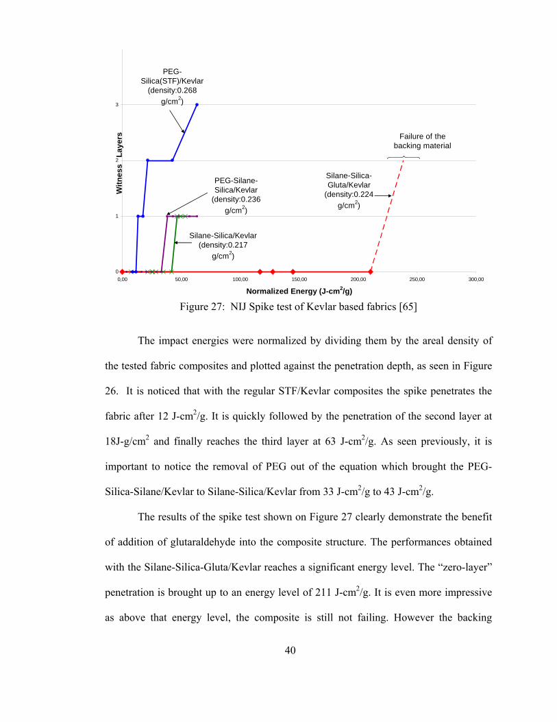
Figure 27: NIJ Spike test of Kevlar based fabrics [65]
The impact energies were normalized by dividing them by the areal density of
the tested fabric composites and plotted against the penetration depth, as seen in Figure
26. It is noticed that with the regular STF/Kevlar composites the spike penetrates the
fabric after 12 J-cm2/g. It is quickly followed by the penetration of the second layer at
18J-g/cm2 and finally reaches the third layer at 63 J-cm2/g. As seen previously, it is
important to notice the removal of PEG out of the equation which brought the PEG-
Silica-Silane/Kevlar to Silane-Silica/Kevlar from 33 J-cm2/g to 43 J-cm2/g.
The results of the spike test shown on Figure 27 clearly demonstrate the benefit
of addition of glutaraldehyde into the composite structure. The performances obtained
with the Silane-Silica-Gluta/Kevlar reaches a significant energy level. The “zero-layer”
penetration is brought up to an energy level of 211 J-cm2/g. It is even more impressive
as above that energy level, the composite is still not failing. However the backing
41
material starts failing and gets penetrated by the spike and the fabric reaching 2 layers
of penetration at around 240 J-cm2/g as seen in Figure 27.
The gluta-system clearly shows high improvements compared to the STF fabric
that has been already improved by removing the PEG. The ‘0-level penetration’
increases by 4.5 times the Silane-Silica/Kevlar composite and by 10 times than that of
STF system.
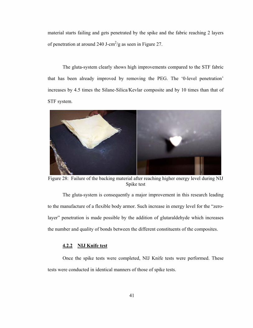
Figure 28: Failure of the backing material after reaching higher energy level during NIJ
Spike test
The gluta-system is consequently a major improvement in this research leading
to the manufacture of a flexible body armor. Such increase in energy level for the “zero-
layer” penetration is made possible by the addition of glutaraldehyde which increases
the number and quality of bonds between the different constituents of the composites.
4.2.2 NIJ Knife test
Once the spike tests were completed, NIJ Knife tests were performed. These
tests were conducted in identical manners of those of spike tests.
42
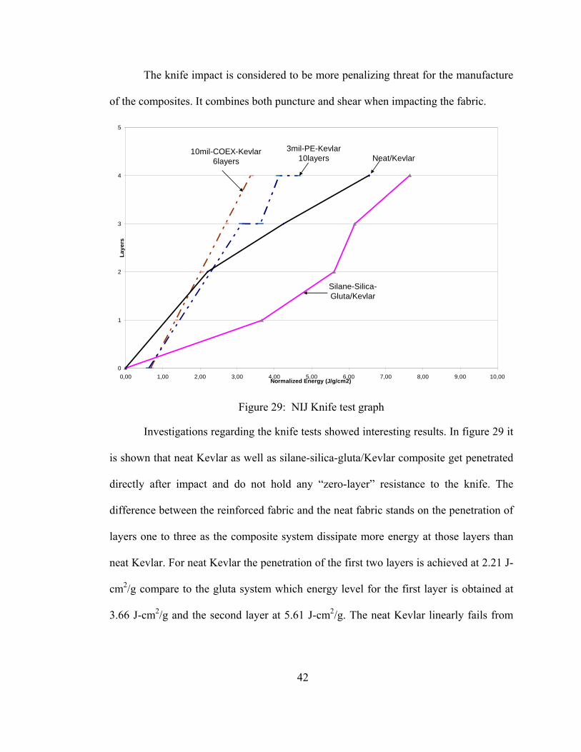
The knife impact is considered to be more penalizing threat for the manufacture
of the composites. It combines both puncture and shear when impacting the fabric.
Silane-Silica-Gluta/Kevlar
10mil-COEX-Kevlar 6layers
3mil-PE-Kevlar 10layers Neat/Kevlar
0
1
2
3
4
5
0,00 1,00 2,00 3,00 4,00 5,00 6,00 7,00 8,00 9,00 10,00Normalized Energy (J/g/cm2)
Laye
rs
Figure 29: NIJ Knife test graph
Investigations regarding the knife tests showed interesting results. In figure 29 it
is shown that neat Kevlar as well as silane-silica-gluta/Kevlar composite get penetrated
directly after impact and do not hold any “zero-layer” resistance to the knife. The
difference between the reinforced fabric and the neat fabric stands on the penetration of
layers one to three as the composite system dissipate more energy at those layers than
neat Kevlar. For neat Kevlar the penetration of the first two layers is achieved at 2.21 J-
cm2/g compare to the gluta system which energy level for the first layer is obtained at
3.66 J-cm2/g and the second layer at 5.61 J-cm2/g. The neat Kevlar linearly fails from
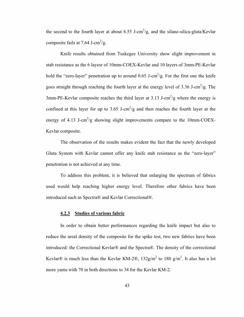
43
the second to the fourth layer at about 6.55 J-cm2/g, and the silane-silica-gluta/Kevlar
composite fails at 7.64 J-cm2/g.
Knife results obtained from Tuskegee University show slight improvement in
stab resistance as the 6 layesr of 10mm-COEX-Kevlar and 10 layers of 3mm-PE-Kevlar
hold the “zero-layer” penetration up to around 0.65 J-cm2/g. For the first one the knife
goes straight through reaching the fourth layer at the energy level of 3.36 J-cm2/g. The
3mm-PE-Kevlar composite reaches the third layer at 3.13 J-cm2/g where the energy is
confined at this layer for up to 3.65 J-cm2/g and then reaches the fourth layer at the
energy of 4.13 J-cm2/g showing slight improvements compare to the 10mm-COEX-
Kevlar composite.
The observation of the results makes evident the fact that the newly developed
Gluta System with Kevlar cannot offer any knife stab resistance as the “zero-layer”
penetration is not achieved at any time.
To address this problem, it is believed that enlarging the spectrum of fabrics
used would help reaching higher energy level. Therefore other fabrics have been
introduced such as Spectra® and Kevlar Correctional®.
4.2.3 Studies of various fabric
In order to obtain better performances regarding the knife impact but also to
reduce the areal density of the composite for the spike test, two new fabrics have been
introduced: the Correctional Kevlar® and the Spectra®. The density of the correctional
Kevlar® is much less than the Kevlar KM-2®, 132g/m2 to 180 g/m2. It also has a lot
more yarns with 70 in both directions to 34 for the Kevlar KM-2.
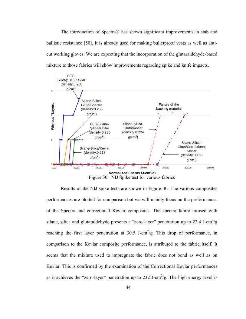
44
The introduction of Spectra® has shown significant improvements in stab and
ballistic resistance [50]. It is already used for making bulletproof vests as well as anti-
cut working gloves. We are expecting that the incorporation of the glutaraldehyde-based
mixture to those fabrics will show improvements regarding spike and knife impacts.
PEG-Silane-Silica/Kevlar
(density:0.236 g/cm2)
Silane-Silica/Kevlar(density:0.217
g/cm2)
Silane-Silica-Gluta/Kevlar
(density:0.224 g/cm2)
Failure of the backing material
PEG-Silica(STF)/Kevlar
(density:0.268 g/cm2)
Silane-Silica-Gluta/Correctional
Kevlar(density:0.158
g/cm2)
Silane-Silica-Gluta/Spectra (density:0.255
g/cm2)
0
1
2
3
0,00 50,00 100,00 150,00 200,00 250,00 300,00 350,00
Normalized Energy (J-cm2/g)
Witn
ess
Lay
ers
Figure 30: NIJ Spike test for various fabrics
Results of the NIJ spike tests are shown in Figure 30. The various composites
performances are plotted for comparison but we will mainly focus on the performances
of the Spectra and correctional Kevlar composites. The spectra fabric infused with
silane, silica and glutaraldehyde presents a “zero-layer” penetration up to 22.4 J-cm2/g
reaching the first layer penetration at 30.5 J-cm2/g. This drop of performance, in
comparison to the Kevlar composite performance, is attributed to the fabric itself. It
seems that the mixture used to impregnate the fabric does not bond as well as on
Kevlar. This is confirmed by the examination of the Correctional Kevlar performances
as it achieves the “zero-layer” penetration up to 232 J-cm2/g. The high energy level is
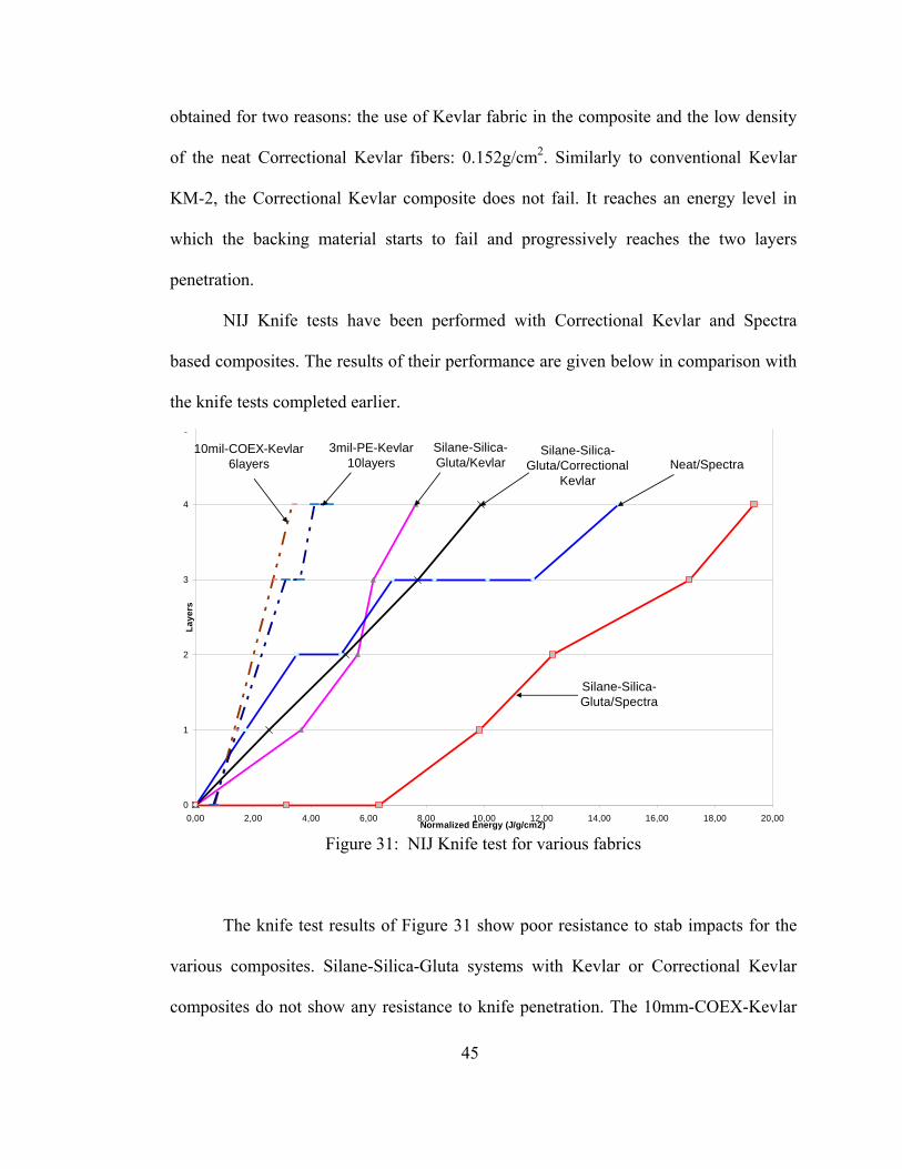
45
obtained for two reasons: the use of Kevlar fabric in the composite and the low density
of the neat Correctional Kevlar fibers: 0.152g/cm2. Similarly to conventional Kevlar
KM-2, the Correctional Kevlar composite does not fail. It reaches an energy level in
which the backing material starts to fail and progressively reaches the two layers
penetration.
NIJ Knife tests have been performed with Correctional Kevlar and Spectra
based composites. The results of their performance are given below in comparison with
the knife tests completed earlier.
Silane-Silica-Gluta/Spectra
Silane-Silica-Gluta/Kevlar
Silane-Silica-Gluta/Correctional
KevlarNeat/Spectra
10mil-COEX-Kevlar 6layers
3mil-PE-Kevlar 10layers
0
1
2
3
4
5
0,00 2,00 4,00 6,00 8,00 10,00 12,00 14,00 16,00 18,00 20,00Normalized Energy (J/g/cm2)
Laye
rs
Figure 31: NIJ Knife test for various fabrics
The knife test results of Figure 31 show poor resistance to stab impacts for the
various composites. Silane-Silica-Gluta systems with Kevlar or Correctional Kevlar
composites do not show any resistance to knife penetration. The 10mm-COEX-Kevlar
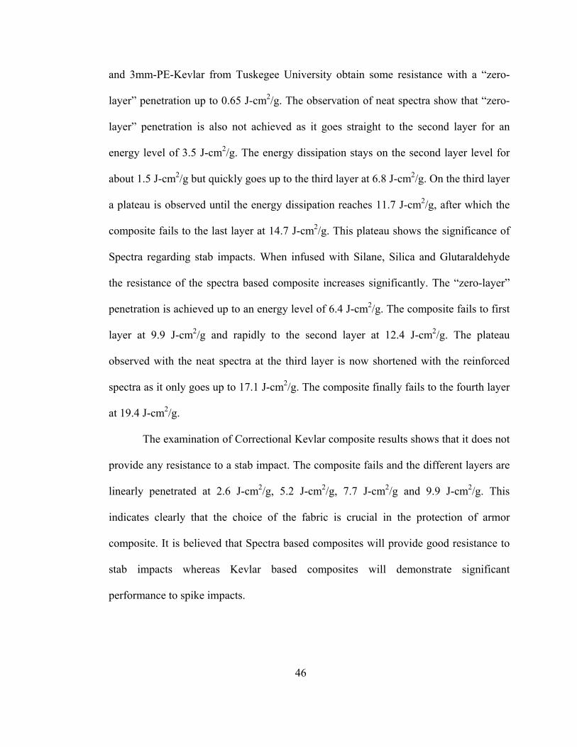
46
and 3mm-PE-Kevlar from Tuskegee University obtain some resistance with a “zero-
layer” penetration up to 0.65 J-cm2/g. The observation of neat spectra show that “zero-
layer” penetration is also not achieved as it goes straight to the second layer for an
energy level of 3.5 J-cm2/g. The energy dissipation stays on the second layer level for
about 1.5 J-cm2/g but quickly goes up to the third layer at 6.8 J-cm2/g. On the third layer
a plateau is observed until the energy dissipation reaches 11.7 J-cm2/g, after which the
composite fails to the last layer at 14.7 J-cm2/g. This plateau shows the significance of
Spectra regarding stab impacts. When infused with Silane, Silica and Glutaraldehyde
the resistance of the spectra based composite increases significantly. The “zero-layer”
penetration is achieved up to an energy level of 6.4 J-cm2/g. The composite fails to first
layer at 9.9 J-cm2/g and rapidly to the second layer at 12.4 J-cm2/g. The plateau
observed with the neat spectra at the third layer is now shortened with the reinforced
spectra as it only goes up to 17.1 J-cm2/g. The composite finally fails to the fourth layer
at 19.4 J-cm2/g.
The examination of Correctional Kevlar composite results shows that it does not
provide any resistance to a stab impact. The composite fails and the different layers are
linearly penetrated at 2.6 J-cm2/g, 5.2 J-cm2/g, 7.7 J-cm2/g and 9.9 J-cm2/g. This
indicates clearly that the choice of the fabric is crucial in the protection of armor
composite. It is believed that Spectra based composites will provide good resistance to
stab impacts whereas Kevlar based composites will demonstrate significant
performance to spike impacts.
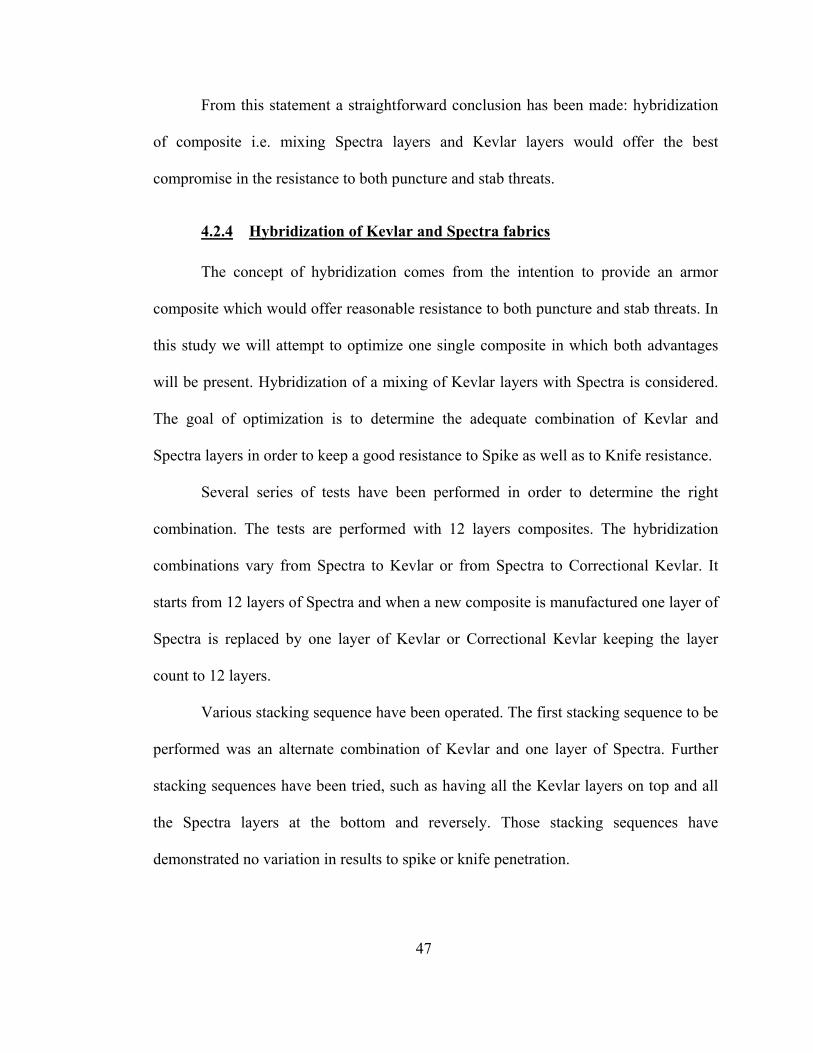
47
From this statement a straightforward conclusion has been made: hybridization
of composite i.e. mixing Spectra layers and Kevlar layers would offer the best
compromise in the resistance to both puncture and stab threats.
4.2.4 Hybridization of Kevlar and Spectra fabrics
The concept of hybridization comes from the intention to provide an armor
composite which would offer reasonable resistance to both puncture and stab threats. In
this study we will attempt to optimize one single composite in which both advantages
will be present. Hybridization of a mixing of Kevlar layers with Spectra is considered.
The goal of optimization is to determine the adequate combination of Kevlar and
Spectra layers in order to keep a good resistance to Spike as well as to Knife resistance.
Several series of tests have been performed in order to determine the right
combination. The tests are performed with 12 layers composites. The hybridization
combinations vary from Spectra to Kevlar or from Spectra to Correctional Kevlar. It
starts from 12 layers of Spectra and when a new composite is manufactured one layer of
Spectra is replaced by one layer of Kevlar or Correctional Kevlar keeping the layer
count to 12 layers.
Various stacking sequence have been operated. The first stacking sequence to be
performed was an alternate combination of Kevlar and one layer of Spectra. Further
stacking sequences have been tried, such as having all the Kevlar layers on top and all
the Spectra layers at the bottom and reversely. Those stacking sequences have
demonstrated no variation in results to spike or knife penetration.
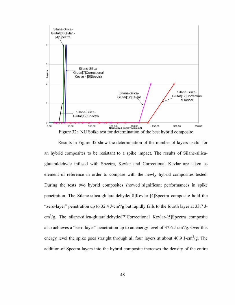
48
Silane-Silica-Gluta/[12]Spectra
Silane-Silica-Gluta/[12]Kevlar
Silane-Silica-Gluta/[12]Correction
al Kevlar
Silane-Silica-Gluta/[7]Correctional Kevlar - [5]Spectra
Silane-Silica-Gluta/[8]Kevlar -
[4]Spectra
0
1
2
3
4
0,00 50,00 100,00 150,00 200,00 250,00 300,00 350,00Normalized Energy (J/g/cm2)
Laye
rs
Figure 32: NIJ Spike test for determination of the best hybrid composite
Results in Figure 32 show the determination of the number of layers useful for
an hybrid composites to be resistant to a spike impact. The results of Silane-silica-
glutaraldehyde infused with Spectra, Kevlar and Correctional Kevlar are taken as
element of reference in order to compare with the newly hybrid composites tested.
During the tests two hybrid composites showed significant performances in spike
penetration. The Silane-silica-glutaraldehyde/[8]Kevlar-[4]Spectra composite hold the
“zero-layer” penetration up to 32.4 J-cm2/g but rapidly fails to the fourth layer at 33.7 J-
cm2/g. The silane-silica-glutaraldehyde/[7]Correctional Kevlar-[5]Spectra composite
also achieves a “zero-layer” penetration up to an energy level of 37.6 J-cm2/g. Over this
energy level the spike goes straight through all four layers at about 40.9 J-cm2/g. The
addition of Spectra layers into the hybrid composite increases the density of the entire
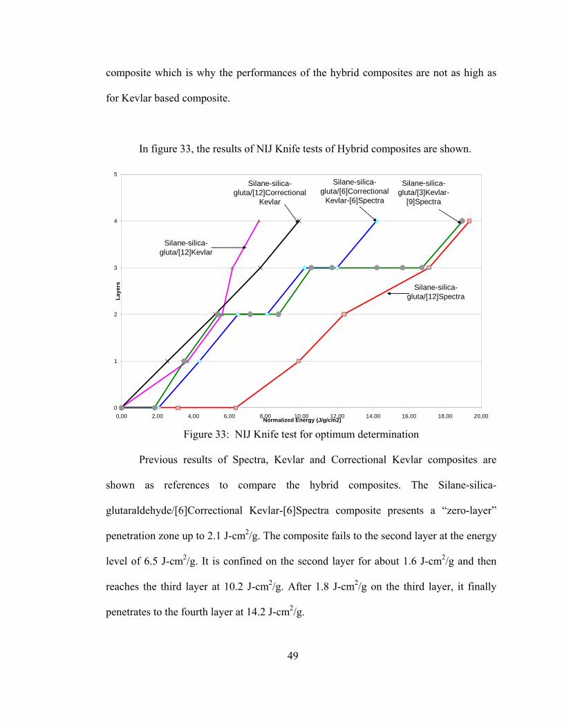
49
composite which is why the performances of the hybrid composites are not as high as
for Kevlar based composite.
In figure 33, the results of NIJ Knife tests of Hybrid composites are shown.
Silane-silica-gluta/[12]Spectra
Silane-silica-gluta/[12]Kevlar
Silane-silica-gluta/[12]Correctional
Kevlar
Silane-silica-gluta/[6]Correctional
Kevlar-[6]Spectra
Silane-silica-gluta/[3]Kevlar-
[9]Spectra
0
1
2
3
4
5
0,00 2,00 4,00 6,00 8,00 10,00 12,00 14,00 16,00 18,00 20,00Normalized Energy (J/g/cm2)
Laye
rs
Figure 33: NIJ Knife test for optimum determination
Previous results of Spectra, Kevlar and Correctional Kevlar composites are
shown as references to compare the hybrid composites. The Silane-silica-
glutaraldehyde/[6]Correctional Kevlar-[6]Spectra composite presents a “zero-layer”
penetration zone up to 2.1 J-cm2/g. The composite fails to the second layer at the energy
level of 6.5 J-cm2/g. It is confined on the second layer for about 1.6 J-cm2/g and then
reaches the third layer at 10.2 J-cm2/g. After 1.8 J-cm2/g on the third layer, it finally
penetrates to the fourth layer at 14.2 J-cm2/g.
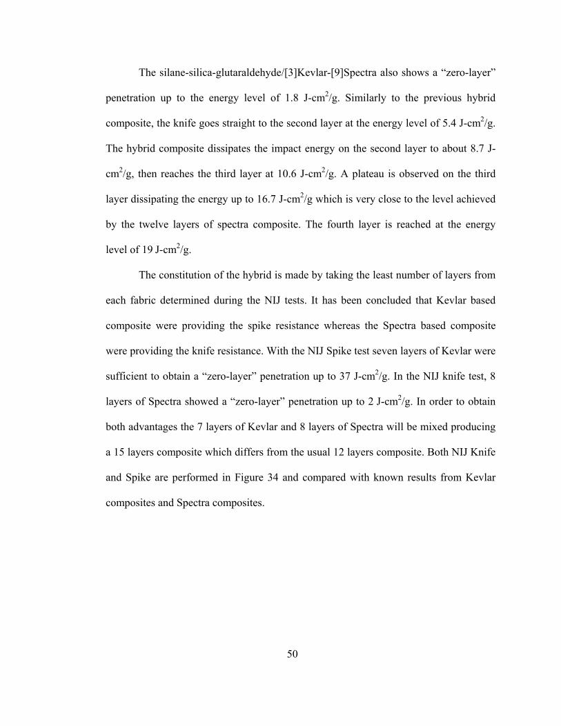
50
The silane-silica-glutaraldehyde/[3]Kevlar-[9]Spectra also shows a “zero-layer”
penetration up to the energy level of 1.8 J-cm2/g. Similarly to the previous hybrid
composite, the knife goes straight to the second layer at the energy level of 5.4 J-cm2/g.
The hybrid composite dissipates the impact energy on the second layer to about 8.7 J-
cm2/g, then reaches the third layer at 10.6 J-cm2/g. A plateau is observed on the third
layer dissipating the energy up to 16.7 J-cm2/g which is very close to the level achieved
by the twelve layers of spectra composite. The fourth layer is reached at the energy
level of 19 J-cm2/g.
The constitution of the hybrid is made by taking the least number of layers from
each fabric determined during the NIJ tests. It has been concluded that Kevlar based
composite were providing the spike resistance whereas the Spectra based composite
were providing the knife resistance. With the NIJ Spike test seven layers of Kevlar were
sufficient to obtain a “zero-layer” penetration up to 37 J-cm2/g. In the NIJ knife test, 8
layers of Spectra showed a “zero-layer” penetration up to 2 J-cm2/g. In order to obtain
both advantages the 7 layers of Kevlar and 8 layers of Spectra will be mixed producing
a 15 layers composite which differs from the usual 12 layers composite. Both NIJ Knife
and Spike are performed in Figure 34 and compared with known results from Kevlar
composites and Spectra composites.
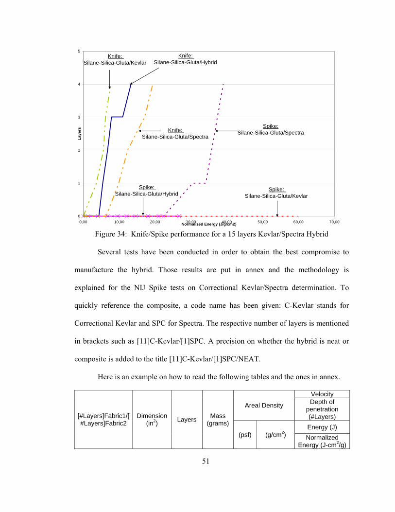
51
0
1
2
3
4
5
0,00 10,00 20,00 30,00 40,00 50,00 60,00 70,00Normalized Energy (J/g/cm2)
Laye
rs
Knife: Silane-Silica-Gluta/Hybrid
Spike:Silane-Silica-Gluta/Spectra
Spike: Silane-Silica-Gluta/Kevlar
Knife: Silane-Silica-Gluta/Spectra
Knife: Silane-Silica-Gluta/Kevlar
Spike: Silane-Silica-Gluta/Hybrid
Figure 34: Knife/Spike performance for a 15 layers Kevlar/Spectra Hybrid
Several tests have been conducted in order to obtain the best compromise to
manufacture the hybrid. Those results are put in annex and the methodology is
explained for the NIJ Spike tests on Correctional Kevlar/Spectra determination. To
quickly reference the composite, a code name has been given: C-Kevlar stands for
Correctional Kevlar and SPC for Spectra. The respective number of layers is mentioned
in brackets such as [11]C-Kevlar/[1]SPC. A precision on whether the hybrid is neat or
composite is added to the title [11]C-Kevlar/[1]SPC/NEAT.
Here is an example on how to read the following tables and the ones in annex.
[#Layers]Fabric1/[#Layers]Fabric2
Dimension (in2) Layers Mass
(grams)
Areal Density
Velocity Depth of
penetration (#Layers)
(psf) (g/cm2) Energy (J) Normalized
Energy (J-cm2/g)
52
On the tests recorded in the table 2, it is possible to retrieve the data from which
the determination of the hybrid composite has been possible. The velocity are recorded
and then computed to determine the amount of energy. This energy is normalized by the
areal density in order to compare all the results from different fabrics which would have
had more or less density.
As an example in the table below we can clearly see how important is the
Spectra in the hybrid composite. The more layers the hybrid possesses, the higher
energy it reaches on NIJ Knife test. The removal of one Spectra layer and replacement
with a Correctional Kevlar layer instead decrease slowly the resistance of the hybrid to
the stab threat.
For instance the [1]C-Kevlar/[11]SPC/composite goes up to an energy level of
about 18.99J-cm2/g whereas the [11]C-Kevlar/[1]SPC/composite only goes up to 10.74
J-cm2/g.
By doing so we were able to determine the right number of layers from each
fabric to produce the hybrid composite.
4.2.5 Introduction of CaCo3
It has been shown that resistance to spike and stab threats were in part obtained
by the addition of nanoparticles. Up to now, various forms of silica nanoparticles have
been utilized. But only silica has been utilized in order to correlate with the STF theory.
As the STF has been discarded throughout the investigation, introduction of new
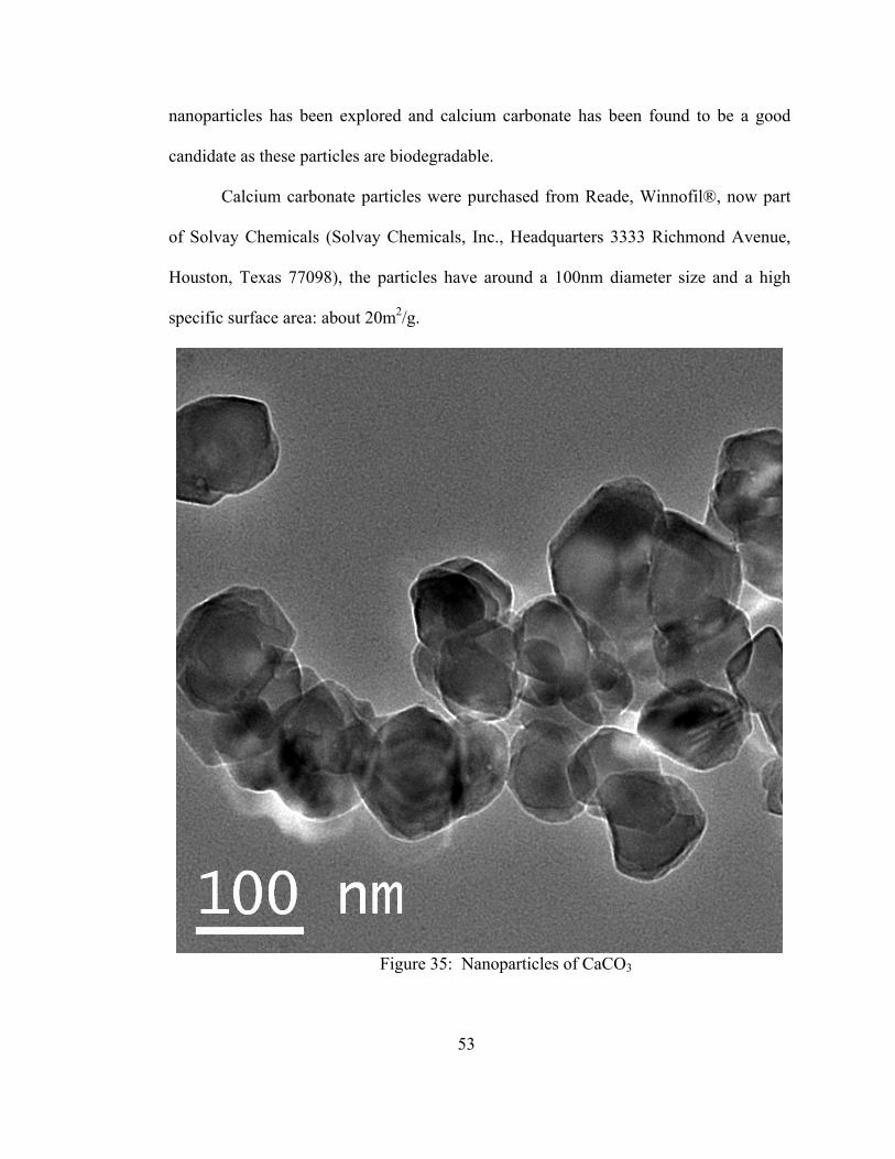
53
nanoparticles has been explored and calcium carbonate has been found to be a good
candidate as these particles are biodegradable.
Calcium carbonate particles were purchased from Reade, Winnofil®, now part
of Solvay Chemicals (Solvay Chemicals, Inc., Headquarters 3333 Richmond Avenue,
Houston, Texas 77098), the particles have around a 100nm diameter size and a high
specific surface area: about 20m2/g.
Figure 35: Nanoparticles of CaCO3
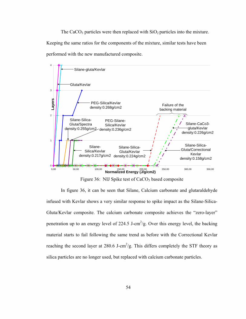
54
The CaCO3 particles were then replaced with SiO2 particles into the mixture.
Keeping the same ratios for the components of the mixture, similar tests have been
performed with the new manufactured composite.
PEG-Silane-Silica/Kevlar
density:0.236g/cm2
Silane-Silica/Kevlar
density:0.217g/cm2
Silane-Silica-Gluta/Kevlar
density:0.224g/cm2
Failure of the backing material
PEG-Silica/Kevlar density:0.268g/cm2
Silane-Silica-Gluta/Correctional
Kevlar density:0.158g/cm2
Silane-Silica-Gluta/Spectra
density:0.255g/cm2Silane-CaCo3-
gluta/Kevlardensity:0.226g/cm2
Silane-gluta/Kevlar
Gluta/Kevlar
0
1
2
3
4
0,00 50,00 100,00 150,00 200,00 250,00 300,00 350,00Normalized Energy (J/g/cm2)
Laye
rs
Figure 36: NIJ Spike test of CaCO3 based composite
In figure 36, it can be seen that Silane, Calcium carbonate and glutaraldehyde
infused with Kevlar shows a very similar response to spike impact as the Silane-Silica-
Gluta/Kevlar composite. The calcium carbonate composite achieves the “zero-layer”
penetration up to an energy level of 224.5 J-cm2/g. Over this energy level, the backing
material starts to fail following the same trend as before with the Correctional Kevlar
reaching the second layer at 280.6 J-cm2/g. This differs completely the STF theory as
silica particles are no longer used, but replaced with calcium carbonate particles.

55
Samples of Kevlar impregnated with glutaraldehyde only and with silane and
glutaraldehyde have been tested in order to better understand the implication of the
glutaraldehyde in the composite manufacture. Both composites do not show any
resistance to spike impacts. The spike goes directly through all four layers at an energy
level of 12.2 J-cm2/g for the gluta/Kevlar composite and 17.5 J-cm2/g for the silane-
gluta/Kevlar composite.
Figure 37 shows NIJ Knife test results for Silane-calcium carbonate-
glutaraldehyde/Kevlar composite.
Silane-Silica-Gluta/Spectra
Silane-Silica-Gluta/Kevlar Silane-Silica-
Gluta/Correctional Kevlar
Neat/Spectra
10mil-COEX-Kevlar 6layers
3mil-PE-Kevlar 10layers
Silane-CaCO3-Gluta/Kevlar
0
1
2
3
4
5
0,00 2,00 4,00 6,00 8,00 10,00 12,00 14,00 16,00 18,00 20,00Normalized Energy (J/g/cm2)
Laye
rs
Figure 37: NIJ Knife test of CaCO3 based composite
The silane, calcium carbonate and glutaraldehyde with Kevlar composite shows
pour resistance to stab impacts as it does not achieve the “zero-layer” penetration. The
penetration goes straight to the first layer at 3.2 J-cm2/g and gradually goes through all

56
the layers respectively at 4.7 J-cm2/g for the second, 5.7 J-cm2/g for the third and 6.7 J-
cm2/g for the fourth.
4.2.6 Failure Analysis
A failure analysis has been performed in order to establish the differences
between the knife and the spike penetration. To observe the fundamental differences
between those two modes of failure, some electron microscopy pictures have been taken
of the composites after impact. The fabrics studied are Kevlar reinforced with silane-
silica-glutaraldehyde and the Spectra with the same mixture. In all cases, the first layer
of each composite has been chosen to perform the analysis. Therefore a higher level of
damages can be observed which would lead to a better understanding of the failure
mechanisms involved during those impacts.
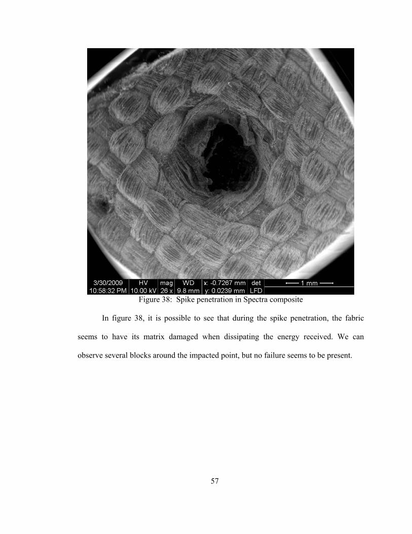
57
Figure 38: Spike penetration in Spectra composite
In figure 38, it is possible to see that during the spike penetration, the fabric
seems to have its matrix damaged when dissipating the energy received. We can
observe several blocks around the impacted point, but no failure seems to be present.
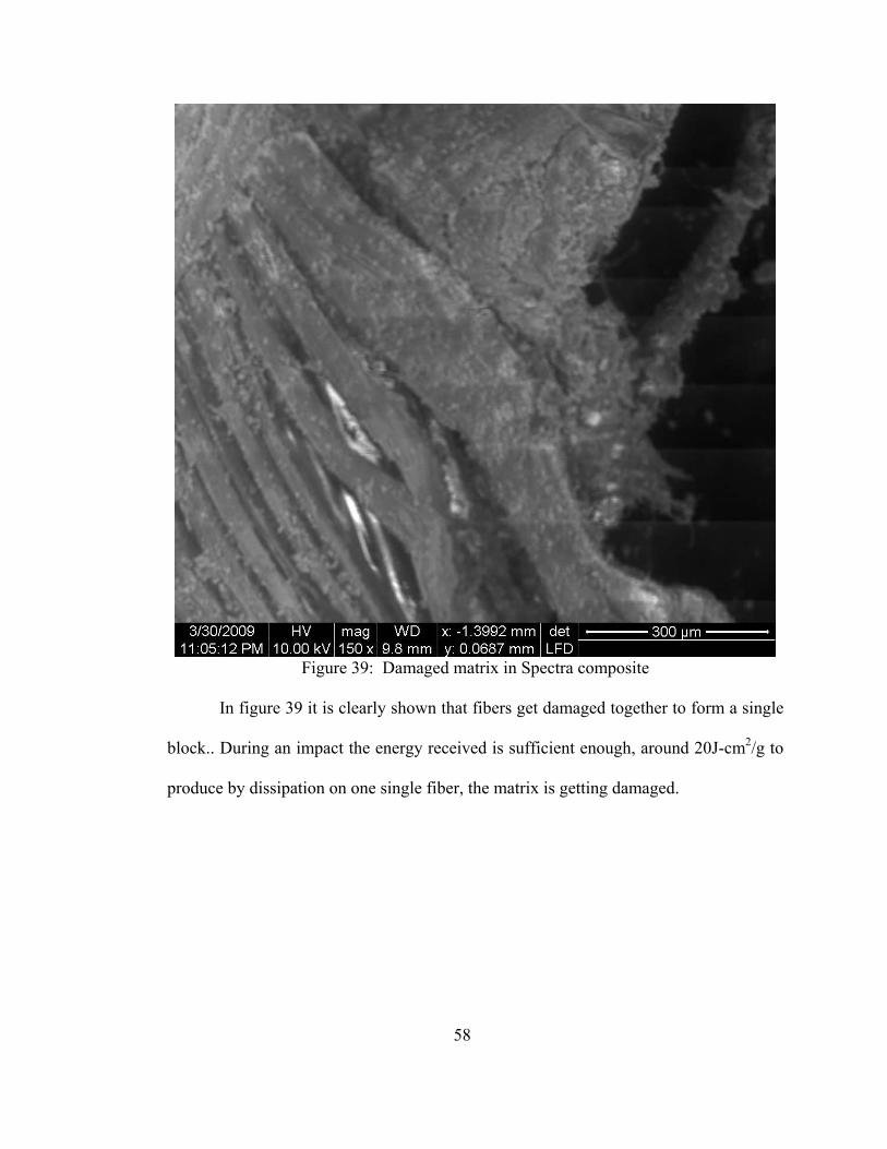
58
Figure 39: Damaged matrix in Spectra composite
In figure 39 it is clearly shown that fibers get damaged together to form a single
block.. During an impact the energy received is sufficient enough, around 20J-cm2/g to
produce by dissipation on one single fiber, the matrix is getting damaged.
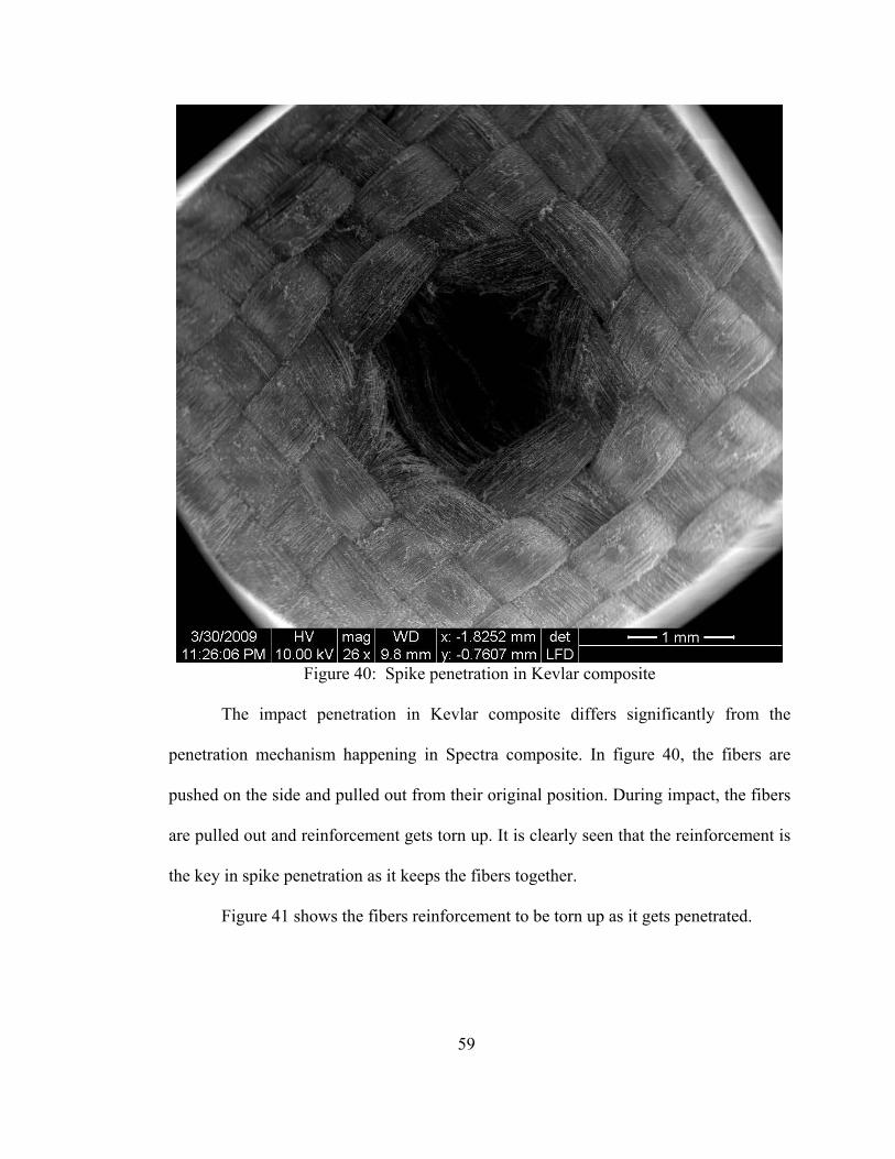
59
Figure 40: Spike penetration in Kevlar composite
The impact penetration in Kevlar composite differs significantly from the
penetration mechanism happening in Spectra composite. In figure 40, the fibers are
pushed on the side and pulled out from their original position. During impact, the fibers
are pulled out and reinforcement gets torn up. It is clearly seen that the reinforcement is
the key in spike penetration as it keeps the fibers together.
Figure 41 shows the fibers reinforcement to be torn up as it gets penetrated.
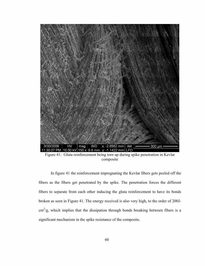
60
Figure 41: Gluta reinforcement being torn up during spike penetration in Kevlar
composite
In figure 41 the reinforcement impregnating the Kevlar fibers gets peeled off the
fibers as the fibers get penetrated by the spike. The penetration forces the different
fibers to separate from each other inducing the gluta reinforcement to have its bonds
broken as seen in Figure 41. The energy received is also very high, to the order of 200J-
cm2/g, which implies that the dissipation through bonds breaking between fibers is a
significant mechanism in the spike resistance of the composite.
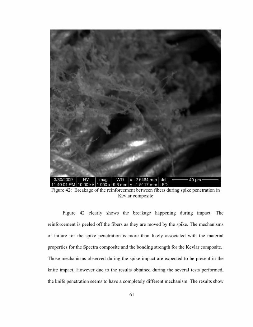
61
Figure 42: Breakage of the reinforcement between fibers during spike penetration in
Kevlar composite
Figure 42 clearly shows the breakage happening during impact. The
reinforcement is peeled off the fibers as they are moved by the spike. The mechanisms
of failure for the spike penetration is more than likely associated with the material
properties for the Spectra composite and the bonding strength for the Kevlar composite.
Those mechanisms observed during the spike impact are expected to be present in the
knife impact. However due to the results obtained during the several tests performed,
the knife penetration seems to have a completely different mechanism. The results show

62
that Spectra performs better than Kevlar. Study of the failure mechanism should give an
indication regarding this wide variation in performance.
Figure 43: Knife penetration in Spectra composite
Figure 43 shows a good picture of a knife penetration. We can see the puncture
point performed at impact on the top of the opening. Lower to this triangular shape
impact, it is possible to see the cut done by the blade of the knife. Similar comments can
be done regarding the triangular impact hole observed at the top of the penetration.
However the cut obtained by the blade shows a different mechanism. The fibers seem to
be cut and not moved or pulled out. A zoom in to this area shows that the fibers have

63
both mechanisms involved. The energy received is dissipated through either a matrix
damage as observed in the bottom of Figure 44, or a fiber cut at the top.
Figure 44: Zoom in the area where the cut is done by the blade in the Spectra
composite
The examination of the fibers cut shows that an important extension occurred
before rupture. This can be seen on the fibers in figure 44 where a thin piece of fabric is
curling at the end of the fibers showing reduction of cross section occurring during
tension and which happened during the impact. A closer look at those fiber cut can be
seen in figure 45.
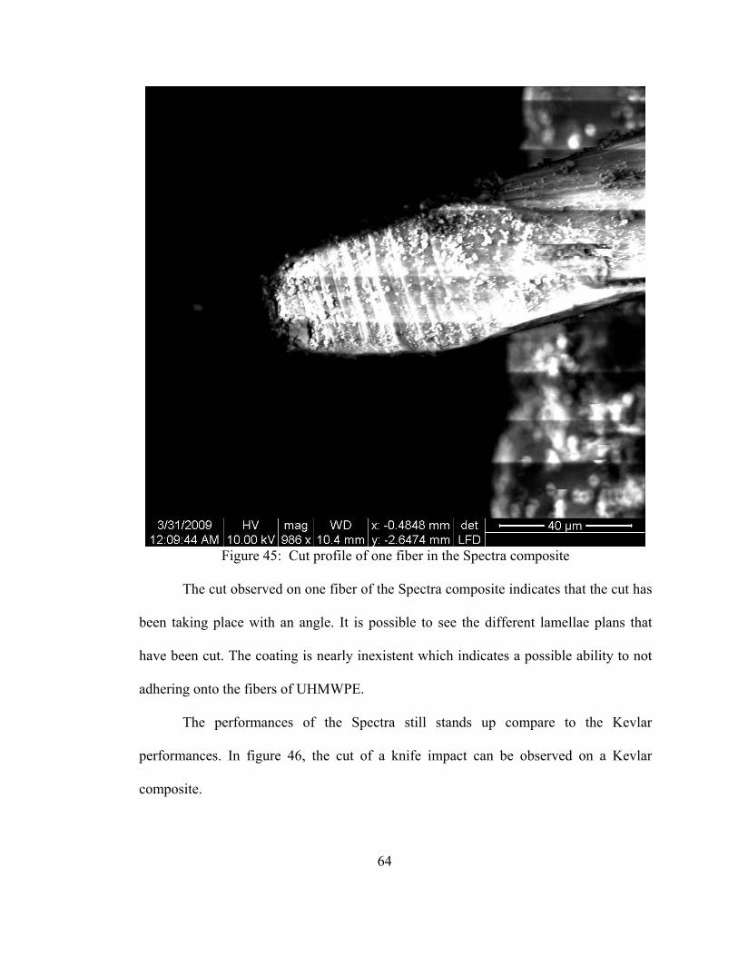
64
Figure 45: Cut profile of one fiber in the Spectra composite
The cut observed on one fiber of the Spectra composite indicates that the cut has
been taking place with an angle. It is possible to see the different lamellae plans that
have been cut. The coating is nearly inexistent which indicates a possible ability to not
adhering onto the fibers of UHMWPE.
The performances of the Spectra still stands up compare to the Kevlar
performances. In figure 46, the cut of a knife impact can be observed on a Kevlar
composite.
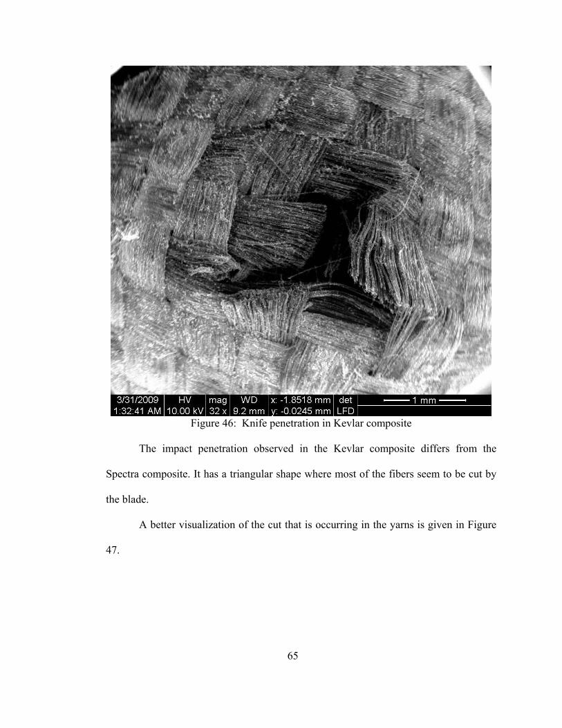
65
Figure 46: Knife penetration in Kevlar composite
The impact penetration observed in the Kevlar composite differs from the
Spectra composite. It has a triangular shape where most of the fibers seem to be cut by
the blade.
A better visualization of the cut that is occurring in the yarns is given in Figure
47.

66
Figure 47: Yarn cut in Kevlar composite
Contrary to the Spectra composite, the Kevlar composite shows a cleaner
straight cut as seen in figure 47. The fibers are all cut at the same time and do not show
any type of deformation behavior such as the one seen with Spectra fibers. Figure 48
confirms the fact that each individual fiber fails quickly after impact.

67
Figure 48: Fiber cut in Kevlar composite
It appears that during impact the fiber is being cut without offering much
resistance, not a very high elastic deformation. The figure shows that the fiber keeps its
dimensions until the area of impact where a swelling is observed at the end of the fiber.
This can be attributed by the elastic reaction that occurs after failure: the fiber retracts
on itself forming those little bulbs at the tip of the cut fiber. The reinforcement after
impact is still well present which indicates that the failure mode occurring during knife
impacts are mainly due to the fabric properties rather than the present reinforcement.
68
To summarize the analysis, we can explain that after the observation of the spike
and knife penetration in both cases: Kevlar and Spectra composites. The mechanisms
operating during the penetration is slightly different in each case and would then
explain the wide variation happening in resistance performances. During spike
penetration the Kevlar composite shows high resistance to the penetration due to the
reinforcement bonding to the fibers. On the other hand, Spectra shows more difficulties
for the mixture to bond onto the fibers and would then explain the drop of
performances. Also when impacted the energy dissipating into the fabric is damaging
the matrix that can be shown around the impact location. This mechanism is also
occurring during knife penetration, but it is believed to that the increase in resistance to
knife for the Spectra composite compared to the Kevlar composite is mainly due to the
deformation of each fiber. The fibers get stretched and in that way are slowing down the
fall of the knife. This can be correlated with some mechanical testing performed later
on, where tension in shear direction shows high strain for the Spectra composite. On the
opposite, the Kevlar composite, show nearly no resistance to the knife penetration.
Despite the reinforcement the knife cut all the fibers in a clean cut with no other
mechanism involved.
4.2.7 Difference between Spike and Knife impact
The wide variation observed between the spike and the knife performances with
Kevlar and Spectra composite are believed to be mainly due to both the ability of the
bonding of the reinforcement and the fabric material properties. The question occurring
after the NIJ tests and mechanical testing performed on the Spectra and Kevlar
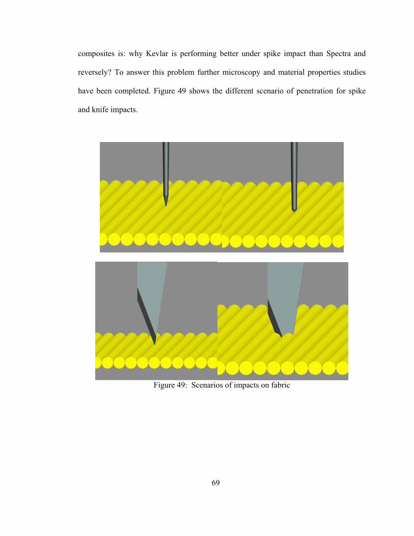
69
composites is: why Kevlar is performing better under spike impact than Spectra and
reversely? To answer this problem further microscopy and material properties studies
have been completed. Figure 49 shows the different scenario of penetration for spike
and knife impacts.
Figure 49: Scenarios of impacts on fabric

70
Figure 50 shows the silane-silica-glutaraldehyde bonding onto the Kevlar.
Figure 50: A thin coating of silated SiO2 with glutaraldehyde mixture on the surface of
the Kevlar fabric
The reinforcement is well attached to the fibers and a uniform coating is
provided onto the fibers. Few agglomerates are presents and bonding between fibers is
observed. It is believed that such bonding is providing the resistance to the spike
penetration for the Kevlar composite. The study of single reinforced fibers shows that
the coating is not only deposited on the surface of the fabric but is uniformly

71
encompassing each single fiber with the mixture. This can be clearly observed in Figure
50.
Figure 51: Silane-Silica-Gluta/Kevlar bonding
On the other hand, the impregnation of Spectra fabric with the silane-silica-
glutaraldehyde mixture does not seem to bond as well. Figure 51 shows that the
reinforcement coated onto the Spectra fibers does not bond uniformly. Large areas of
fibers are not covered and more agglomerates are present. The study based on the NIJ
Spike test show that both neat Kevlar and neat Spectra have similar performance.
However after the impregnation of silane-silica-glutaraldehyde onto the Kevlar fabric
the resistance to the spike penetration is significantly improved. This is simply not the
case regarding the Spectra fibers which still show poor performances after being
treated. The observation of the coating of the reinforcement onto the fibers is an
explanation to this variation in spike resistance and is further explained by the
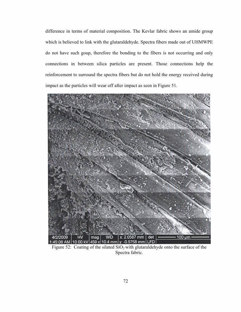
72
difference in terms of material composition. The Kevlar fabric shows an amide group
which is believed to link with the glutaraldehyde. Spectra fibers made out of UHMWPE
do not have such goup, therefore the bonding to the fibers is not occurring and only
connections in between silica particles are present. Those connections help the
reinforcement to surround the spectra fibers but do not hold the energy received during
impact as the particles will wear off after impact as seen in Figure 51.
Figure 52: Coating of the silated SiO2 with glutaraldehyde onto the surface of the
Spectra fabric.

73
Figure 53: Coating of the silated SiO2 with glutaraldehyde mixture wearing off the
surface of the Spectra fabric after impact.
The presence of reinforcement deposited onto the Spectra fibers still helps
improving the performances of the composite. The examination of the NIJ knife test
results shows that reinforced Spectra fabric performs better than neat Spectra. This
believed to results in part from the reinforcement deposition at the surface of the fibers.
Even though the reinforcement does not bond to the fibers the thin coating existing
provides the first line of defense to the knife impact. Further studies on NIJ knife test
show that Spectra presents at the third layer penetration, a plateau of resistance which
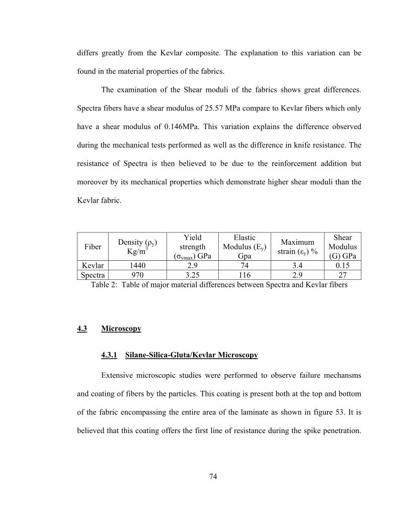
74
differs greatly from the Kevlar composite. The explanation to this variation can be
found in the material properties of the fabrics.
The examination of the Shear moduli of the fabrics shows great differences.
Spectra fibers have a shear modulus of 25.57 MPa compare to Kevlar fibers which only
have a shear modulus of 0.146MPa. This variation explains the difference observed
during the mechanical tests performed as well as the difference in knife resistance. The
resistance of Spectra is then believed to be due to the reinforcement addition but
moreover by its mechanical properties which demonstrate higher shear moduli than the
Kevlar fabric.
Fiber Density (ρy) Kg/m3
Yield strength
(σymax) GPa
Elastic Modulus (Ey)
Gpa
Maximum strain (εy) %
Shear Modulus (G) GPa
Kevlar 1440 2.9 74 3.4 0.15 Spectra 970 3.25 116 2.9 27
Table 2: Table of major material differences between Spectra and Kevlar fibers
4.3 Microscopy
4.3.1 Silane-Silica-Gluta/Kevlar Microscopy
Extensive microscopic studies were performed to observe failure mechansms
and coating of fibers by the particles. This coating is present both at the top and bottom
of the fabric encompassing the entire area of the laminate as shown in figure 53. It is
believed that this coating offers the first line of resistance during the spike penetration.

75
The coating consists of agglomerated silica particles embedded in the body of the
matrix as in Figure 55.
Figure 54: A thin coating of the silated SiO2 with glutaraldehyde mixture on the surface
of the Kevlar fabric
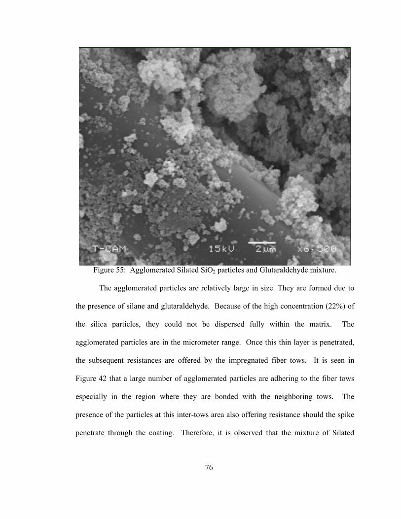
76
Figure 55: Agglomerated Silated SiO2 particles and Glutaraldehyde mixture.
The agglomerated particles are relatively large in size. They are formed due to
the presence of silane and glutaraldehyde. Because of the high concentration (22%) of
the silica particles, they could not be dispersed fully within the matrix. The
agglomerated particles are in the micrometer range. Once this thin layer is penetrated,
the subsequent resistances are offered by the impregnated fiber tows. It is seen in
Figure 42 that a large number of agglomerated particles are adhering to the fiber tows
especially in the region where they are bonded with the neighboring tows. The
presence of the particles at this inter-tows area also offering resistance should the spike
penetrate through the coating. Therefore, it is observed that the mixture of Silated
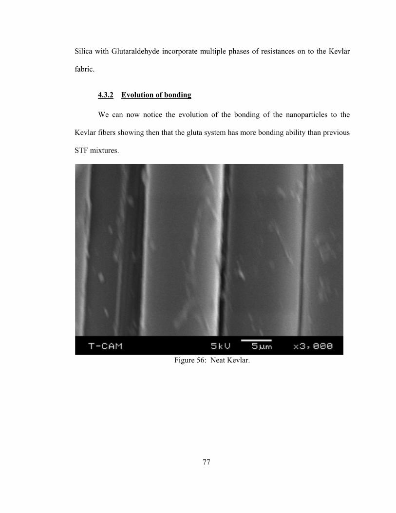
77
Silica with Glutaraldehyde incorporate multiple phases of resistances on to the Kevlar
fabric.
4.3.2 Evolution of bonding
We can now notice the evolution of the bonding of the nanoparticles to the
Kevlar fibers showing then that the gluta system has more bonding ability than previous
STF mixtures.
Figure 56: Neat Kevlar.
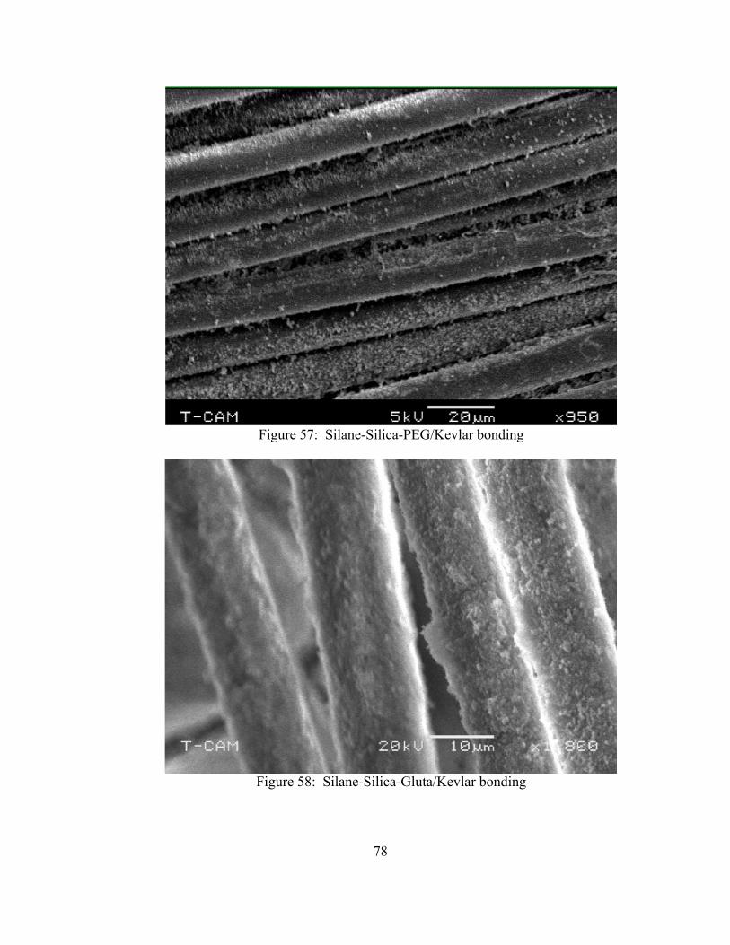
78
Figure 57: Silane-Silica-PEG/Kevlar bonding
Figure 58: Silane-Silica-Gluta/Kevlar bonding
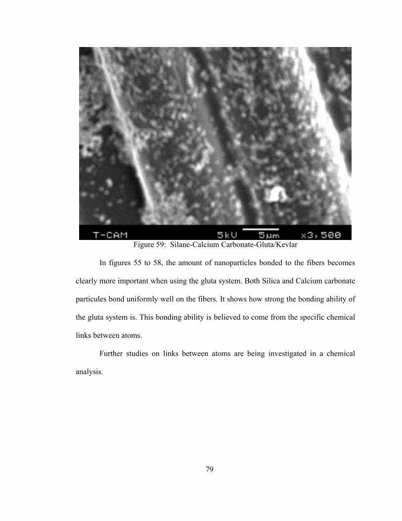
79
Figure 59: Silane-Calcium Carbonate-Gluta/Kevlar
In figures 55 to 58, the amount of nanoparticles bonded to the fibers becomes
clearly more important when using the gluta system. Both Silica and Calcium carbonate
particules bond uniformly well on the fibers. It shows how strong the bonding ability of
the gluta system is. This bonding ability is believed to come from the specific chemical
links between atoms.
Further studies on links between atoms are being investigated in a chemical
analysis.
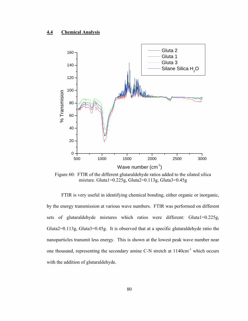
80
4.4 Chemical Analysis
500 1000 1500 2000 2500 30000
20
40
60
80
100
120
140
160
% T
rans
mis
ion
Wave number (cm-1)
Gluta 2 Gluta 1 Gluta 3 Silane Silica H2O
Figure 60: FTIR of the different glutaraldehyde ratios added to the silated silica
mixture. Gluta1=0.225g, Gluta2=0.113g, Gluta3=0.45g
FTIR is very useful in identifying chemical bonding, either organic or inorganic,
by the energy transmission at various wave numbers. FTIR was performed on different
sets of glutaraldehyde mixtures which ratios were different: Gluta1=0.225g,
Gluta2=0.113g, Gluta3=0.45g. It is observed that at a specific glutaraldehyde ratio the
nanoparticles transmit less energy. This is shown at the lowest peak wave number near
one thousand, representing the secondary amine C-N stretch at 1140cm-1 which occurs
with the addition of glutaraldehyde.
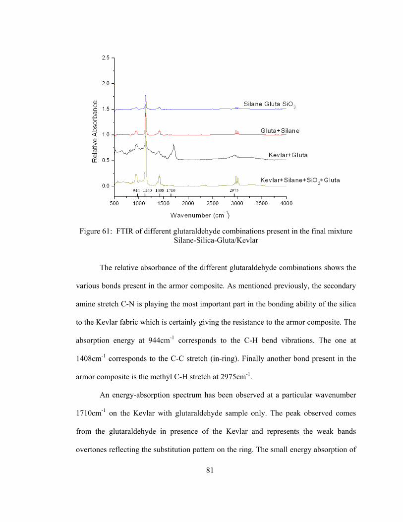
81
Figure 61: FTIR of different glutaraldehyde combinations present in the final mixture
Silane-Silica-Gluta/Kevlar
The relative absorbance of the different glutaraldehyde combinations shows the
various bonds present in the armor composite. As mentioned previously, the secondary
amine stretch C-N is playing the most important part in the bonding ability of the silica
to the Kevlar fabric which is certainly giving the resistance to the armor composite. The
absorption energy at 944cm-1 corresponds to the C-H bend vibrations. The one at
1408cm-1 corresponds to the C-C stretch (in-ring). Finally another bond present in the
armor composite is the methyl C-H stretch at 2975cm-1.
An energy-absorption spectrum has been observed at a particular wavenumber
1710cm-1 on the Kevlar with glutaraldehyde sample only. The peak observed comes
from the glutaraldehyde in presence of the Kevlar and represents the weak bands
overtones reflecting the substitution pattern on the ring. The small energy absorption of
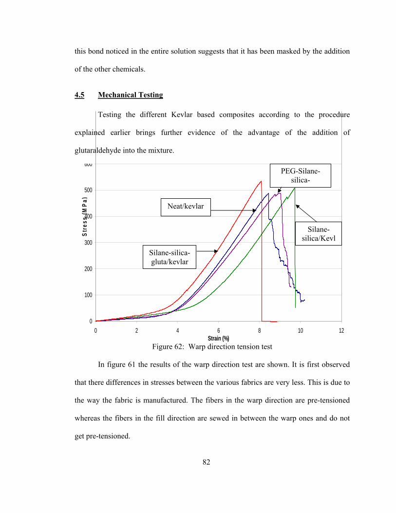
82
this bond noticed in the entire solution suggests that it has been masked by the addition
of the other chemicals.
4.5 Mechanical Testing
Testing the different Kevlar based composites according to the procedure
explained earlier brings further evidence of the advantage of the addition of
glutaraldehyde into the mixture.
Figure 62: Warp direction tension test
In figure 61 the results of the warp direction test are shown. It is first observed
that there differences in stresses between the various fabrics are very less. This is due to
the way the fabric is manufactured. The fibers in the warp direction are pre-tensioned
whereas the fibers in the fill direction are sewed in between the warp ones and do not
get pre-tensioned.
0
100
200
300
400
500
600
0 2 4 6 8 10 12Strain (%)
Stre
ss (M
Pa)
Silane-silica-gluta/kevlar
Neat/kevlar
PEG-Silane-silica-
Silane-silica/Kevl
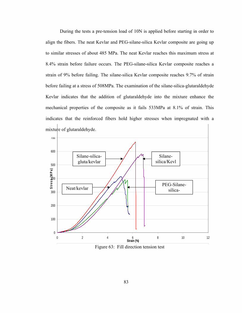
83
During the tests a pre-tension load of 10N is applied before starting in order to
align the fibers. The neat Kevlar and PEG-silane-silica Kevlar composite are going up
to similar stresses of about 485 MPa. The neat Kevlar reaches this maximum stress at
8.4% strain before failure occurs. The PEG-silane-silica Kevlar composite reaches a
strain of 9% before failing. The silane-silica Kevlar composite reaches 9.7% of strain
before failing at a stress of 508MPa. The examination of the silane-silica-glutaraldehyde
Kevlar indicates that the addition of glutaraldehyde into the mixture enhance the
mechanical properties of the composite as it fails 533MPa at 8.1% of strain. This
indicates that the reinforced fibers hold higher stresses when impregnated with a
mixture of glutaraldehyde.
Figure 63: Fill direction tension test
0
100
200
300
400
500
600
700
0 2 4 6 8 10 12Strain (%)
Stre
ss (M
Pa)
Silane-silica-gluta/kevlar
Neat/kevlar PEG-Silane-
silica-
Silane-silica/Kevl
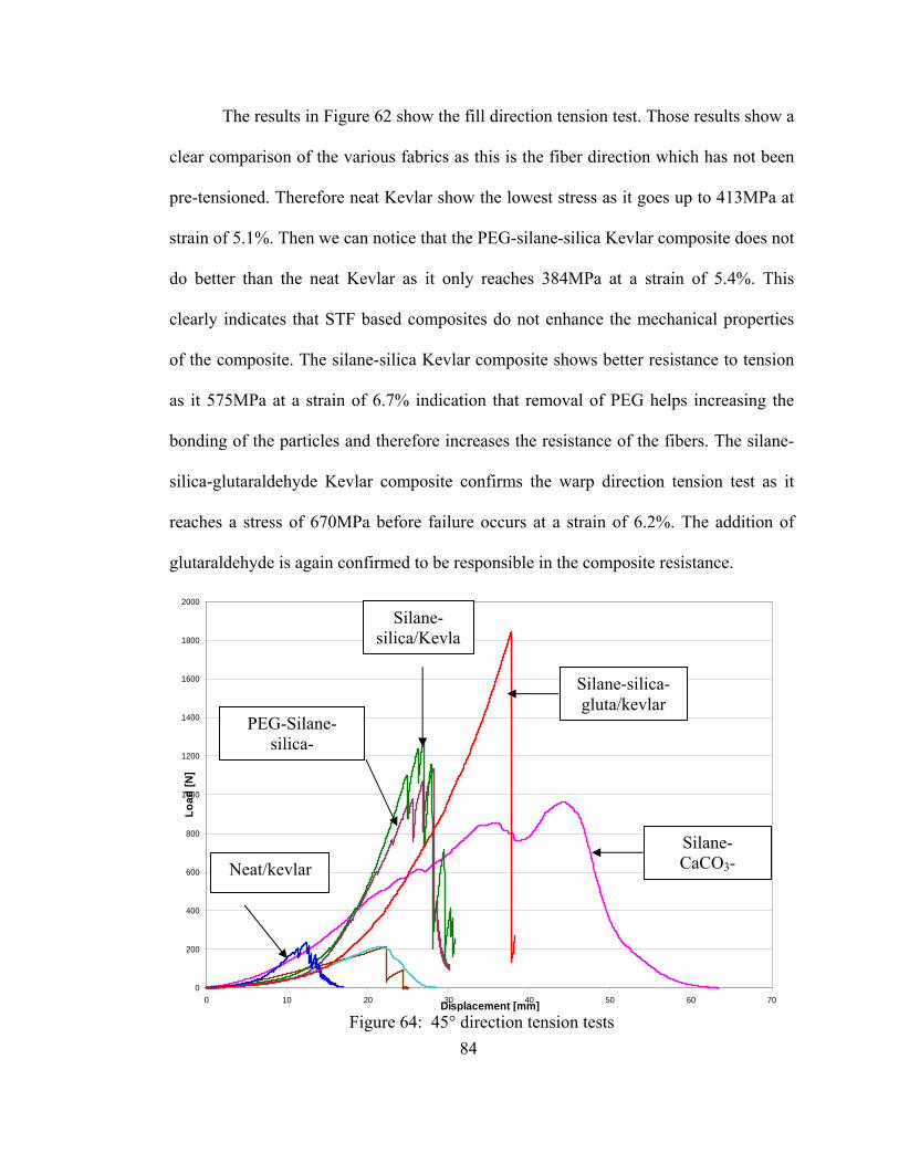
84
The results in Figure 62 show the fill direction tension test. Those results show a
clear comparison of the various fabrics as this is the fiber direction which has not been
pre-tensioned. Therefore neat Kevlar show the lowest stress as it goes up to 413MPa at
strain of 5.1%. Then we can notice that the PEG-silane-silica Kevlar composite does not
do better than the neat Kevlar as it only reaches 384MPa at a strain of 5.4%. This
clearly indicates that STF based composites do not enhance the mechanical properties
of the composite. The silane-silica Kevlar composite shows better resistance to tension
as it 575MPa at a strain of 6.7% indication that removal of PEG helps increasing the
bonding of the particles and therefore increases the resistance of the fibers. The silane-
silica-glutaraldehyde Kevlar composite confirms the warp direction tension test as it
reaches a stress of 670MPa before failure occurs at a strain of 6.2%. The addition of
glutaraldehyde is again confirmed to be responsible in the composite resistance.
Figure 64: 45° direction tension tests
0
200
400
600
800
1000
1200
1400
1600
1800
2000
0 10 20 30 40 50 60 70Displacement [mm]
Load
[N]
Silane-silica-gluta/kevlar
Neat/kevlar
PEG-Silane-silica-
Silane-silica/Kevla
Silane-CaCO3-
85
The [45degre] shear test (ASTM D3518-76) involves uniaxial tension testing of
±45degree composites; usually laminates. The method is used for measuring in-plane
shear properties, such as the shear modulusG12 and the ultimate shear strength τ12 of
unidirectional fiber-reinforced composites. The method used is described earlier in
section 3.4, where samples of 1inch by 6 inches (25.4mmx152.4mm) are tested in
tension with a Zwick/Roell universal testing machine. The gage length for each sample
is about 4inches (101.6mm). The equation that relates the shear strength to the
longitudinal stress is related by the equation: xxστ21
12 = . The shear strain equation is
given by yyxx εεγ −=12 where σxx, εxx, and εyy represent tensile stress, longitudinal
strain and transverse strain respectively. By knowing the samples parameters such as
the thickness, the length and the width, the data obtained during the tension test can be
related to the shear strength.
The shear strength will be crucial in our test as it gives important information on
the bonding between the fibers yarns.
In figure 63, the neat Kevlar shows very little performance as it has no
reinforcement what so ever, meaning no bonding between fibers. The load to fail the
neat Kevlar goes up to 233.6N to a displacement of 12.4mm before failure. The test of
neat nylon also shows pour performance as it reaches a load of 214.2N for a
displacement of 22.3mm. The slow failure of nylon is mainly due to the reorganization
mechanism of the molecular chains within the fibers. The PEG-silane-silica-Kevlar
composite shows higher performance, indicating that reinforced fabric does help
86
increasing the resistance of the fibers. It goes up to 1131.3N and to a displacement of
28.2mm prior failure.
Following a similar trend as the previous mechanical tests, the silane-silica-
kevlar composite is performing better than the PEG-based composite as it reaches a
load of 1282.4N at a displacement of 27mm. The bonding between the fibers is
confirmed to be increased by the removal of the PEG out of the composite manufacture.
The observation of the silane-silica-glutaraldehyde-kevlar composite shows the
highest resistance to the tensile load as it reaches a load of 1844.5N at a displacement of
37.8mm which confirms the high bonding between the fiber yarns. This high bonding
ability is obtained by the addition of glutaraldehyde.
The silane-silica-glutaraldehyde-spectra composite is slowly increasing to
855.6N where it extends its length to about 35.5mm where a rupture partially occurs
within the sample. The resistance continues as the loading goes up and finally reaches
its failure point at 958.8N after an elongation of 44.4mm over its original length.
To further understand the difference occurring during the 45° degree test
between the Kevlar and Spectra composite, some microscopy has been performed.
Figure 64 shows the difference between Kevlar composite before and after the tension
test in a 45 degree direction.
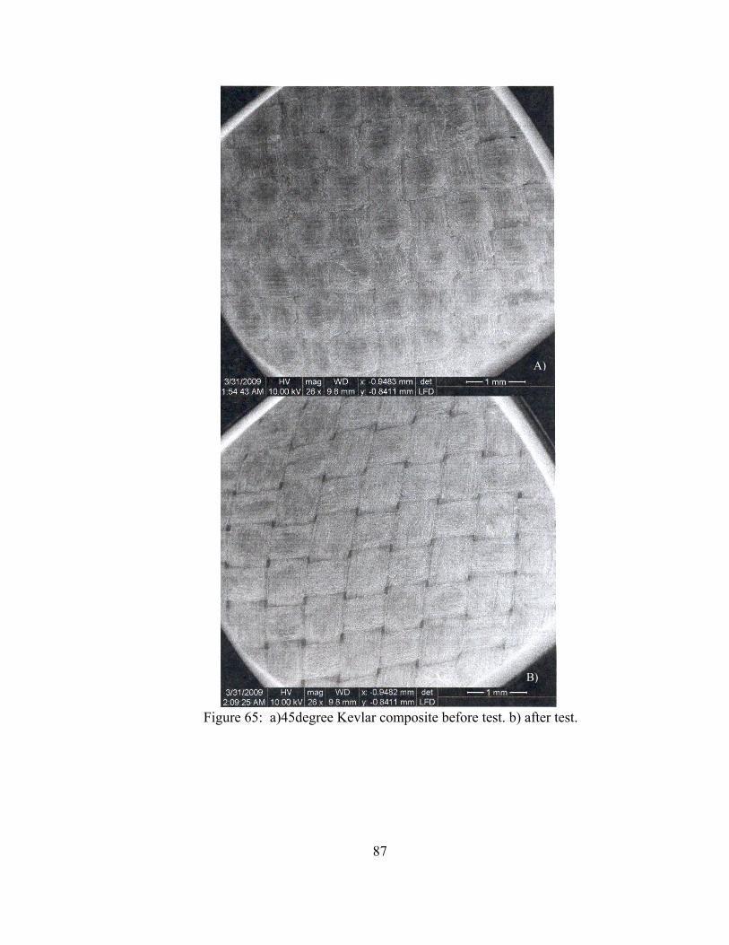
87
Figure 65: a)45degree Kevlar composite before test. b) after test.
A)
B)
88
The difference before and after the test is performed resides mostly in the
orientation of the fibers between each other. The angle starts with a 90degree angle and
slowly decreases as the tension goes on. At the failure point the alignment between the
fibers reaches an angle of approximately 50degree. It is also observed that the
reinforcement has gone away during the test, especially at the intersection between
yarns.
Figure 65 shows the difference between before and after the tension test in a
45degree direction of Spectra composites. The deformation shows a similar yarn
configuration between post and prior tension test. The yarn rotation is around 70degree
which is less than for Kevlar. It also shows that a lot less reinforcement is present at the
surface of the composite. This highlight the fact impregnation of Gluta system on
Spectra fibers do not work as efficiently as it does with Kevlar. This can then be
explained by the fact that Spectra do not exhibit an Amide group in its molecular
formula, which prevents the glutaraldehyde to bond to the surface.

89
Figure 66: a)45degree Spectra composite before test. b) after test.
A)
B)

90
4.6 Flexibility test
According to the flexibility test procedure described in 3.5, several composites
have been tested. The results have been recorded in the following table:
Figure 67: Flexibility Set-up
Although the surface of the armor composites appears to be cracked at some
locations, the flexibility is not compromised. In order to compare flexibility, procedures
outlined in section 2.6 are followed. Twelve 15.2x15.2 cm2 layers of various categories
of fabrics were stacked together and clamped at one end. Clamping width was
maintained at 1.3 cm. The rest of the length, i.e., about 13.9 cm was protruding off from
the clamped end. A total weight of 19.44 g was applied at the free end using an
aluminium strip. Each category of fabric was clamped and loaded in identical manner.
Flex angle for each category are then measured.
TYPE NEAT\Kevlar
NEAT/Correctional Kevlar
Spectra PEG-Silane-Silica\Kevlar
PEG-Silica\Kevl
arANGLE
(deg) 42 30 31 50 31.5
Table 3: Results table for flexibility test on the different armor composites
Silane-Silica\Kevlar
Silane-Silica-gluta\Kevlar
Silane-Silica-gluta\Correctional Kevlar
Silane-CaCo3-
gluta\Kevlar
Silane-Silica-gluta\Spectra
45 40 32.5 33 28
91
Results of flexibility tests show that any Gluta systems stay very flexible. It
slightly varies when compared to the neat fabric. Neat Kevlar has a flex angle of about
42° and the reinforced Kevlar with glutaraldehyde has a 40° angle. Similarly neat
correctional Kevlar has a 30° angle whereas the reinforced one as a 32.5° angle. The
neat Spectra fabric has a 31° angle and the reinforced Spectra fabric has a 28° angle.
We can easily conclude that the reinforcement applied to the fabric has no consequence
on the flexibility of the various composites.
The introduction of new particles such as Calcium carbonate do not have any
influence on flexibility as it is seen that reinforced Kevlar with a mixture of silane,
calcium carbonate and glutaraldehyde shows a flex angle of about 33°.
The PEG-silane-silica/Kevlar composite is the only one showing less flexibility as it has
a 50° angle. This can be explained by the addition of silane which is stiffening the
composite.
The PEG-silica/Kevlar composite has a low angle of 31.5° which can be due to
the high density of PEG into the composite.
The Silane-silica/Kevlar composite stays relatively close to neat Kevlar with a 45°
angle.
A remark can be made regarding the correlation with the density of the
composite. The higher is the density of the composite, the smaller is the flex angle
which is then translated into higher flexibility according to the present standard. A more
comprehensive flexibility test should be found in order to measure more accurately the
flexibility of any composite manufactured.
92
4.7 Discussion
Overall, it is observed that a sonicated mixture of Glutaraldehyde and silated
silica nanoparticles impregnated into Kevlar or Spectra fabric offers significant
resistance to spike penetration as well as to knife penetration. This conclusion has been
drawn from the investigation on STF composite in which PEG has been removed from
the equation. The outcome composite, silane-silica-kevlar showed significant
improvements and a better coating has been observed on SEM pictures indicating
higher number of bonds between particles. This observation led us to the introduction of
glutaraldehyde. This type of formaldehyde was believed to increase the amount of
bonds between silica particles as well as with the Kevlar fibers. By creating strong
covalent bonds with the amino-groups contained in the amino-propyl-trimethoxy-silane
and the amide groups present in the Kevlar fabric, the glutaraldehyde enhances
considerably the adherence of the particles on to the Kevlar. Extensive microscopic
studies revealed this uniform coating on the fibers and chemical studies gives more
details on which atomic linkage is responsible for this improved bonding ability. FTIR
has been performed and strongly reveals the secondary amine stretch C-N at the
wavelength of 1140cm-1 to be the cause of the increased amount of bonds within the
composite. The increased number of bonds brought by the addition of glutaraldehyde
into the mixture is believed to be translated into higher mechanical properties of the
impregnated composite. Several tensile tests have been conducted in warp, fill and 45°
degree direction. The outcome of those tests show that glutaraldehyde based composites
have their mechanical performances greatly increased from neat Kevlar or previous
93
silane-silica-kevlar composites. The gluta-based composite reaches the stresses up to
533MPa in warp direction compared to 508MPa. The difference is more evident in fill
direction tension test where the gluta-based composite reaches a maximum stress of
670MPa compare to the silane-silica-kevlar composite which only goes up to 575MPa.
The study of the 45° degree test gives important strength information on how strong the
bonds created by the glutaraldehyde are. The analysis of the different impact patterns
adds up more details on the failure mechanism of such reinforced fabric: reinforcement
of various fabrics bonds the fibers together and less yarns pullout are observed during
spike impact. On the other hand knife impact patterns show a clean cut through the
fibers as the reinforcement restricts the movement of the fibers when the blade is
penetrating. It indicates that fiber properties play an important role in stab resistance.
This is confirmed when NIJ spike and knife tests are performed on the various selection
of fabrics used. The investigation has concluded that Kevlar based composites
performed very well under spike impacts and Spectra based composites under knife
impacts. For instance the silane-silica-glutaraldehyde-Correctional Kevlar composite
achieves the “zero-layer” penetration up to 232 J-cm2/g for the spike test whereas the
silane-silica-gluta-spectra composite only goes up to 30.5 J-cm2/g. This is the opposite
when NIJ knife tests are performed: spectra-based composite goes up to 6.4 J-cm2/g
whereas the Kevlar-based composites do not even achieve a “zero-layer” penetration.
The concept of hybridization is then introduced to address this problem and offer
protection from both puncture and stab. A Kevlar-Spectra hybrid has been developed
showing relatively good performances to both threats in comparison with the full
composites tested. In other word, the hybrid composed of 7 layers of reinforced Kevlar
94
and 8 layers of reinforced Spectra, is the best compromise to provide resistance from
both the spike and the knife. The hybrid composite achieves the “zero-layer”
penetration up to 4 J-cm2/g for the knife and up to 26.7 J-cm2/g for the spike.
In the attempt to increase the resistance performances the Kevlar fabric, calcium
carbonates nano particles have been introduced in place of the silica particles. Identical
results to that of silica based composites have been observed. This discards further more
the STF theory and opens the researches to new type of particles that could enhance the
fabric.
By reinforcing the fabrics, one could easily believe that flexibility is lost along
the process. However, flexibility is measured by recording the angle with the vertical
for each composite. Most of the composites show no variations in comparison to their
neat fabric.
95
CHAPTER 5. FINITE ELEMENT ANALYSYS OF SPIKE PENETRATION
5.1 The Finite Element Method
The finite element method is a numerical technique for finding approximate
solutions of partial differential equations as well as of integral equations. The solution
approach is based either on eliminating the differential equation completely (steady
state problems), or rendering the PDE into an approximating system of ordinary
differential equations, which are then numerically integrated using standard techniques
such as Euler's method, Runge-Kutta, etc.
In solving partial differential equations, the primary challenge is to create an
equation that approximates the equation to be studied, but is numerically stable,
meaning that errors in the input data and intermediate calculations do not accumulate.
There are many ways of doing this, all with advantages and disadvantages. The Finite
Element Method is a good choice for solving partial differential equations over complex
domains (like cars and oil pipelines), when the domain changes (as during a solid state
reaction with a moving boundary), when the desired precision varies over the entire
domain, or when the solution lacks smoothness. For instance, in the spike penetration
simulation, increased precision of the mesh can be operated over the spike and
decreased over the backing material.
In order to recreate the actual problem using the finite element approach, a
commercial modeler, solver and post-processor called Ansys® is utilized.
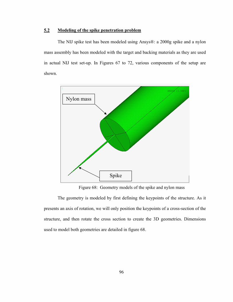
96
5.2 Modeling of the spike penetration problem
The NIJ spike test has been modeled using Ansys®: a 2000g spike and a nylon
mass assembly has been modeled with the target and backing materials as they are used
in actual NIJ test set-up. In Figures 67 to 72, various components of the setup are
shown.
Figure 68: Geometry models of the spike and nylon mass
The geometry is modeled by first defining the keypoints of the structure. As it
presents an axis of rotation, we will only position the keypoints of a cross-section of the
structure, and then rotate the cross section to create the 3D geometries. Dimensions
used to model both geometries are detailed in figure 68.
1
ANSYS 11.0SP1
Nylon mass
Spike
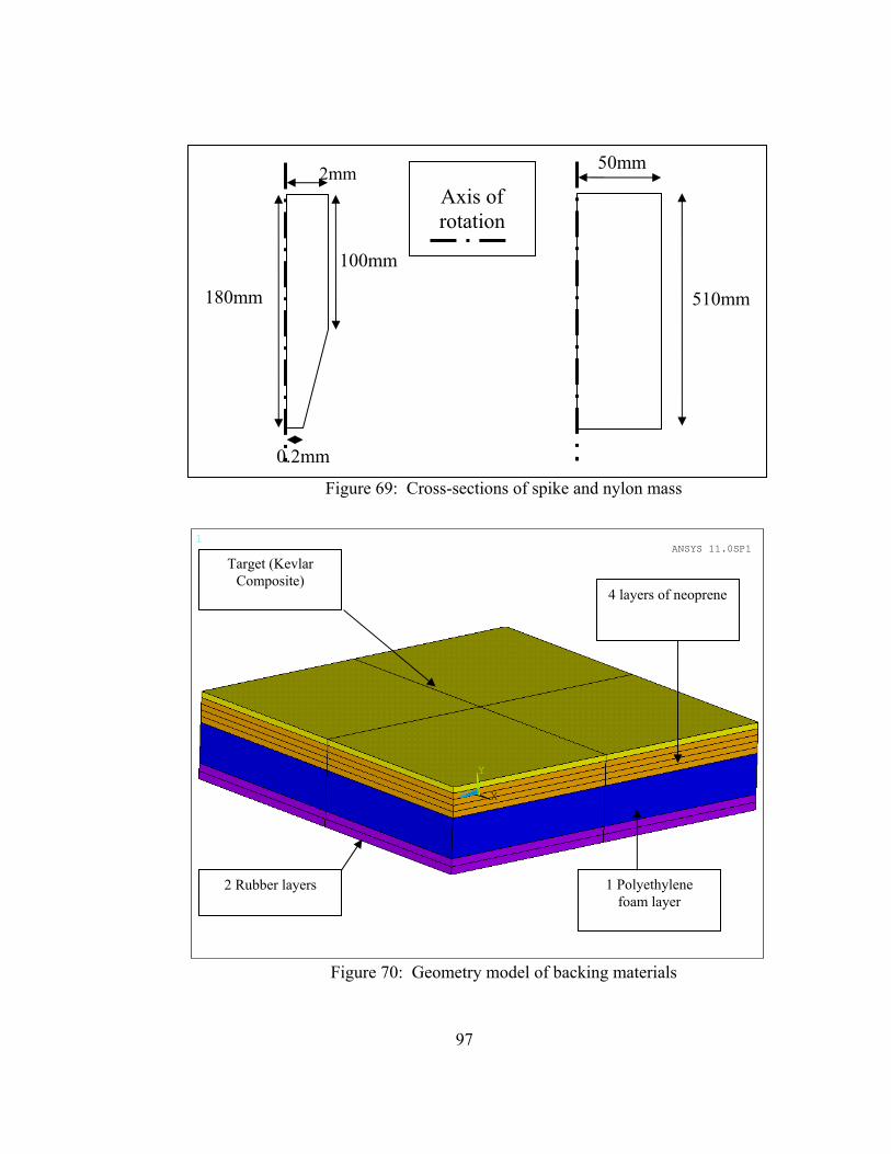
97
Figure 69: Cross-sections of spike and nylon mass
Figure 70: Geometry model of backing materials
180mm
100mm
0.2mm
50mm
510mm
Axis of rotation
2mm
1
X
Y
Z
ANSYS 11.0SP1
2 Rubber layers 1 Polyethylene foam layer
4 layers of neoprene
Target (Kevlar Composite)
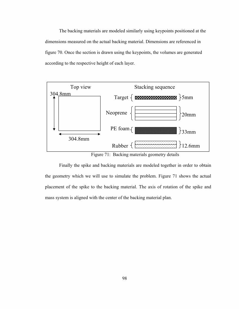
98
The backing materials are modeled similarly using keypoints positioned at the
dimensions measured on the actual backing material. Dimensions are referenced in
figure 70. Once the section is drawn using the keypoints, the volumes are generated
according to the respective height of each layer.
Figure 71: Backing materials geometry details
Finally the spike and backing materials are modeled together in order to obtain
the geometry which we will use to simulate the problem. Figure 71 shows the actual
placement of the spike to the backing material. The axis of rotation of the spike and
mass system is aligned with the center of the backing material plan.
304.8mm
304.8mm
Stacking sequence
Target
Neoprene
PE foam
Rubber 12.6mm
33mm
20mm
5mm
Top view
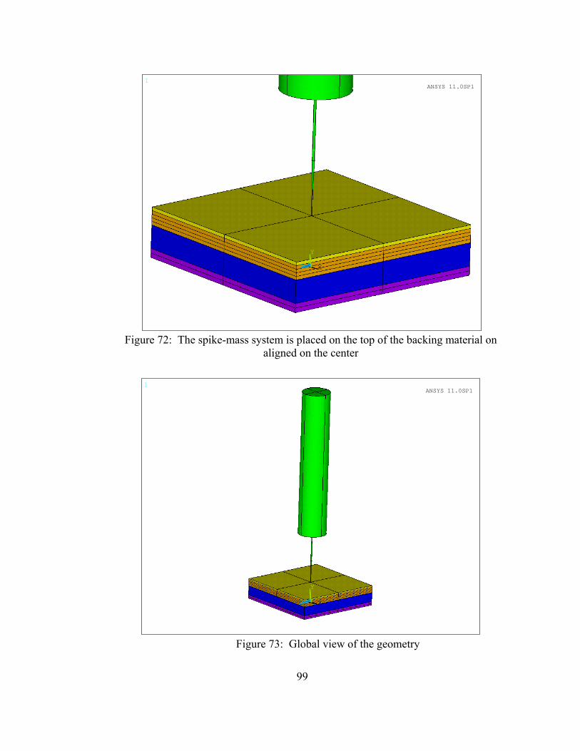
99
1
X
Y
Z
ANSYS 11.0SP1
Figure 72: The spike-mass system is placed on the top of the backing material on
aligned on the center
1
X
Y
Z
ANSYS 11.0SP1
Figure 73: Global view of the geometry

100
The aim of the simulated problem is to study the penetration of a spike into the
composite.
5.3 Elements and mesh generation
After modeling the geometry, the mesh was created using the following
elements. Various elements utilized to mesh the structure are as follows:
SOLID92 is the element type chosen to mesh the plate which is
constituted of 8 layers. 1 layer with the Kevlar properties, 4 layers with
neoprene material, 1 layer with polyethylene foam and 2 layers with
rubber.
SOLID186 is the element type chosen to mesh the spike. It has been
chosen for its characteristics to handle complex sharp shapes as it
presents a high number of nodes.
CONTA178 is an element type called contact element. It allows the
displacement of the spike toward the target.
5.3.1 SOLID92
SOLID92 has a quadratic displacement behavior and is well suited to model
irregular meshes. The element shown in figure 73, is defined by ten nodes having three
degrees of freedom at each node: translations in the nodal x, y, and z directions.
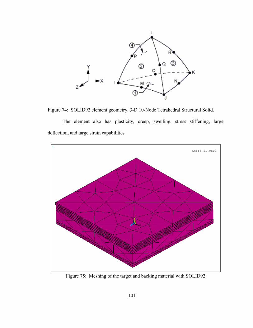
101
Figure 74: SOLID92 element geometry. 3-D 10-Node Tetrahedral Structural Solid.
The element also has plasticity, creep, swelling, stress stiffening, large
deflection, and large strain capabilities
1
X
Y
Z
ANSYS 11.0SP1
Figure 75: Meshing of the target and backing material with SOLID92

102
To mesh the volumes constituting the backing materials, an element size was
chosen. The size had to be not too small in order to avoid too long calculations for the
simulation and not too big in order to provide accurate results. A size of 20mm has been
chosen for the edges of the element. Ansys meshed all volumes based on this element
size.
The solution output associated with element includes as part of other things the
nodal displacement and the stresses in every direction. The element stress directions are
parallel to the element coordinate system. The surface stress outputs are in the surface
coordinate system and are available for any face. The coordinate system for face J-I-K
is shown in figure 75. The other surface coordinate systems follow similar orientations.
Figure 76: SOLID92 stress output
Some restrictions concern the use of this element. The element must not have a
zero volume. Elements may be numbered either as shown in figure 61or may have node
L below the I-J-K plane.
An edge with a removed midside node implies that the displacement varies
linearly, rather than parabolically, along that edge.
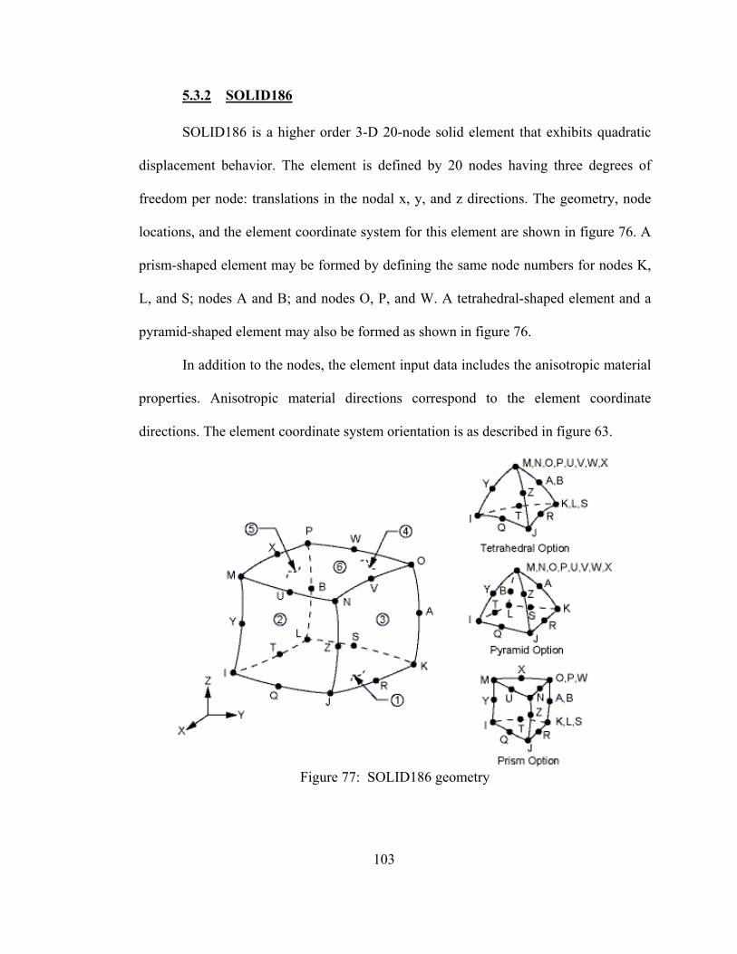
103
5.3.2 SOLID186
SOLID186 is a higher order 3-D 20-node solid element that exhibits quadratic
displacement behavior. The element is defined by 20 nodes having three degrees of
freedom per node: translations in the nodal x, y, and z directions. The geometry, node
locations, and the element coordinate system for this element are shown in figure 76. A
prism-shaped element may be formed by defining the same node numbers for nodes K,
L, and S; nodes A and B; and nodes O, P, and W. A tetrahedral-shaped element and a
pyramid-shaped element may also be formed as shown in figure 76.
In addition to the nodes, the element input data includes the anisotropic material
properties. Anisotropic material directions correspond to the element coordinate
directions. The element coordinate system orientation is as described in figure 63.
Figure 77: SOLID186 geometry
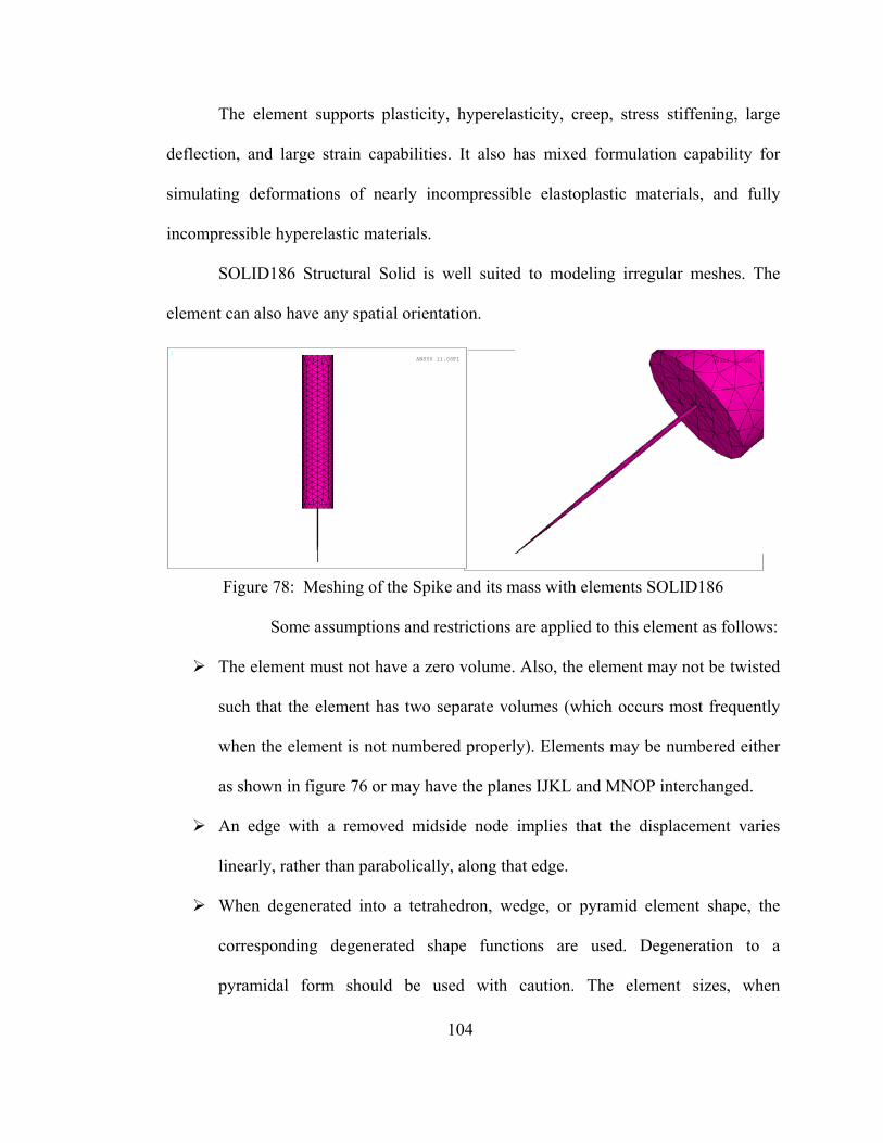
104
The element supports plasticity, hyperelasticity, creep, stress stiffening, large
deflection, and large strain capabilities. It also has mixed formulation capability for
simulating deformations of nearly incompressible elastoplastic materials, and fully
incompressible hyperelastic materials.
SOLID186 Structural Solid is well suited to modeling irregular meshes. The
element can also have any spatial orientation.
Figure 78: Meshing of the Spike and its mass with elements SOLID186
Some assumptions and restrictions are applied to this element as follows:
The element must not have a zero volume. Also, the element may not be twisted
such that the element has two separate volumes (which occurs most frequently
when the element is not numbered properly). Elements may be numbered either
as shown in figure 76 or may have the planes IJKL and MNOP interchanged.
An edge with a removed midside node implies that the displacement varies
linearly, rather than parabolically, along that edge.
When degenerated into a tetrahedron, wedge, or pyramid element shape, the
corresponding degenerated shape functions are used. Degeneration to a
pyramidal form should be used with caution. The element sizes, when
1
ANSYS 11.0SP11
ANSYS 11.0SP1
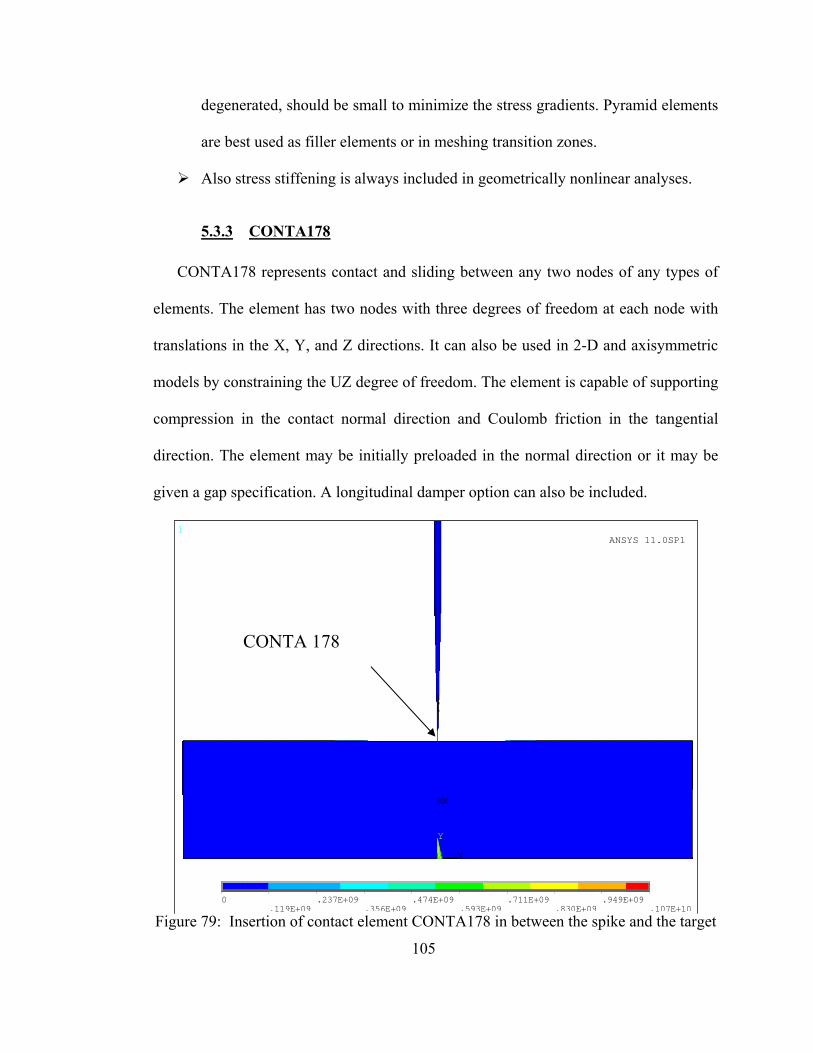
105
degenerated, should be small to minimize the stress gradients. Pyramid elements
are best used as filler elements or in meshing transition zones.
Also stress stiffening is always included in geometrically nonlinear analyses.
5.3.3 CONTA178
CONTA178 represents contact and sliding between any two nodes of any types of
elements. The element has two nodes with three degrees of freedom at each node with
translations in the X, Y, and Z directions. It can also be used in 2-D and axisymmetric
models by constraining the UZ degree of freedom. The element is capable of supporting
compression in the contact normal direction and Coulomb friction in the tangential
direction. The element may be initially preloaded in the normal direction or it may be
given a gap specification. A longitudinal damper option can also be included.
Figure 79: Insertion of contact element CONTA178 in between the spike and the target
1
MX
X
Y
Z
0
.119E+09.237E+09
.356E+09.474E+09
.593E+09.711E+09
.830E+09.949E+09
.107E+10
ANSYS 11.0SP1
CONTA 178
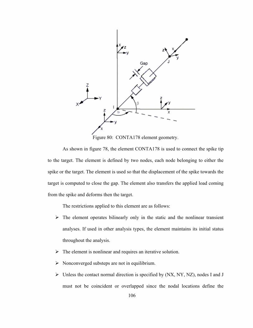
106
Figure 80: CONTA178 element geometry.
As shown in figure 78, the element CONTA178 is used to connect the spike tip
to the target. The element is defined by two nodes, each node belonging to either the
spike or the target. The element is used so that the displacement of the spike towards the
target is computed to close the gap. The element also transfers the applied load coming
from the spike and deforms then the target.
The restrictions applied to this element are as follows:
The element operates bilinearly only in the static and the nonlinear transient
analyses. If used in other analysis types, the element maintains its initial status
throughout the analysis.
The element is nonlinear and requires an iterative solution.
Nonconverged substeps are not in equilibrium.
Unless the contact normal direction is specified by (NX, NY, NZ), nodes I and J
must not be coincident or overlapped since the nodal locations define the
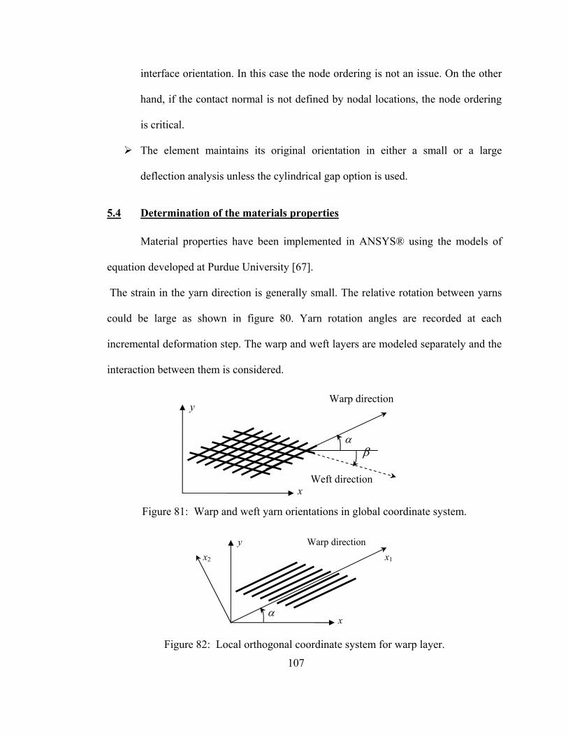
107
interface orientation. In this case the node ordering is not an issue. On the other
hand, if the contact normal is not defined by nodal locations, the node ordering
is critical.
The element maintains its original orientation in either a small or a large
deflection analysis unless the cylindrical gap option is used.
5.4 Determination of the materials properties
Material properties have been implemented in ANSYS® using the models of
equation developed at Purdue University [67].
The strain in the yarn direction is generally small. The relative rotation between yarns
could be large as shown in figure 80. Yarn rotation angles are recorded at each
incremental deformation step. The warp and weft layers are modeled separately and the
interaction between them is considered.
Figure 81: Warp and weft yarn orientations in global coordinate system.
Figure 82: Local orthogonal coordinate system for warp layer.
α β
x
y
Weft direction
Warp direction
αx
y Warp direction x2 x1

108
Considering the warp layer, a local orthogonal coordinate system x1-x2 is set up
with x1 parallel to the yarn direction as shown in Figure 81. The stress-strain relations
for the warp layer are formulated as
11 1 11
22 2 22
12 12 12
0 00 00 0
EE
G
α
α
α
σ εσ εσ γ
⎡ ⎤Δ Δ⎧ ⎫ ⎧ ⎫⎢ ⎥⎪ ⎪ ⎪ ⎪Δ = Δ⎨ ⎬ ⎨ ⎬⎢ ⎥
⎪ ⎪ ⎪ ⎪⎢ ⎥Δ Δ⎩ ⎭ ⎩ ⎭⎣ ⎦
(1)
where 1Eα is curve-fitted using the data from the tension test of the fabric in the warp
direction. It is a function of yarn strain along the warp direction. 2Eα and 12Gα are several
orders smaller than 1Eα . In this study, 12Gα is set to be a constant, and 2Eα is a highly
nonlinear function of nondimensional yarn spacing between warp yarns. The stress-
strain relations in global coordinate system x-y are obtained by coordinate
transformation:
11 12 16
12 22 26
16 26 66
xx xx xx
yy yy yy
xy xy xy
Q Q QQ Q Q QQ Q Q
α α α
α α α α
α α α
σ ε εσ ε εσ γ γ
⎡ ⎤⎧ ⎫ ⎧ ⎫ ⎧ ⎫Δ Δ Δ⎢ ⎥⎪ ⎪ ⎪ ⎪ ⎪ ⎪⎡ ⎤Δ = Δ = Δ⎨ ⎬ ⎨ ⎬ ⎨ ⎬⎢ ⎥ ⎣ ⎦
⎪ ⎪ ⎪ ⎪ ⎪ ⎪⎢ ⎥Δ Δ Δ⎩ ⎭ ⎩ ⎭ ⎩ ⎭⎣ ⎦
(2)
( )
( ) ( )( ) ( )
4 2 2 411 1 12 2
2 212 1 2 12
4 2 2 422 1 12 2
3 316 1 12 2 12
3 326 1 12 2 12
66 1 2
cos 4 sin cos sin
4 sin cos
sin 4 sin cos cos
2 sin cos 2 sin cos
2 sin cos 2 sin cos
Q E G E
Q E E G
Q E G E
Q E G E G
Q E G E G
Q E E
α α α α
α α α α
α α α α
α α α α α
α α α α α
α α α
α α α α
α α
α α α α
α α α α
α α α α
= + +
= + −
= + +
= − − −
= − − −
= +( ) ( )2 2 4 412 122 sin cos sin cosG Gα αα α α α− + +
(3)

109
Following the same procedures, we obtain the stress-strain relations for the weft
layer in the global coordinate system as
11 12 16
12 22 26
16 26 66
xx xx xx
yy yy yy
xy xy xy
Q Q QQ Q Q QQ Q Q
β β β
β β β β
β β β
σ ε εσ ε εσ γ γ
⎡ ⎤⎧ ⎫ ⎧ ⎫ ⎧ ⎫Δ Δ Δ⎢ ⎥⎪ ⎪ ⎪ ⎪ ⎪ ⎪⎡ ⎤Δ = Δ = Δ⎨ ⎬ ⎨ ⎬ ⎨ ⎬⎢ ⎥ ⎣ ⎦
⎪ ⎪ ⎪ ⎪ ⎪ ⎪⎢ ⎥Δ Δ Δ⎩ ⎭ ⎩ ⎭ ⎩ ⎭⎣ ⎦
(4)
( )
( ) ( )( ) ( )
4 2 2 411 1 12 2
2 212 1 2 12
4 2 2 422 1 12 2
3 316 1 12 2 12
3 326 1 12 2 12
66 1 2
cos 4 sin cos sin
4 sin cos
sin 4 sin cos cos
2 sin cos 2 sin cos
2 sin cos 2 sin cos
Q E G E
Q E E G
Q E G E
Q E G E G
Q E G E G
Q E E
β β β α
β β β β
β β β β
β β β β β
β β β β β
β β β
β β β β
β β
β β β β
β β β β
β β β β
= + +
= + −
= + +
= − − −
= − − −
= +( ) ( )2 2 4 412 122 sin cos sin cosG Gβ ββ β β β− + +
(5)
To simplify the formulation, we assume that both warp and weft layers occupy
the same space and have the same thickness 0.23 mmT = as one fabric layer. This
thickness is set to be constant over the fabric undergoing a large deformation. To be
consistent, material properties for the warp and weft layers are defined using thickness
T. Thus the stiffness matrix for the fabric is obtained as
[ ]Q Q Qα β⎡ ⎤ ⎡ ⎤= +⎣ ⎦ ⎣ ⎦ (6)
110
The material properties 1Eα and 1Eβ are obtained from the respective uniaxial
tension tests of the fabric. Bilinear functions of yarn strain are used to fit the stress-
strain curves with the result for kevlar composite:
{ }{ }
( )( ) ϑε
ϑε
ε
ε
αβ
βα
β
β
β
α
α
α
sin1
sin1
067.0,9.101
081.0,1.111
11
11
111
111
+=
+=
≤=
≤=
L
L
GPaL
E
GPaL
E
(7)
where θ α β= − is the angle between warp and weft yarns; 11αε and 11
βε are yarn strains
in warp and weft directions, respectively; Lα and Lβ are nondimensional yarn spacings
for the warp yarns and weft yarns, respectively.
The shear moduli 12Gα and 12Gβ control the initial shear rigidity when the warp and
weft yarns are orthogonal to each other. We have
MPaGGG 4.241212 === βα (8)
The transverse moduli 2Eα and 2Eβ are related to the highly nonlinear shear rigidity
of the fabric under large shear deformation. Physically 2Eα and 2Eβ prevent the parallel
yarns from being too close to each other. We have

111
2 1
2 1
7.80min ,
: Kevlar with par7.80min ,
SilicaLock
SilicaLock
E E MPaL L
E E MPaL L
α α
α
β β
β
⎫⎛ ⎞= ⎪⎜ ⎟−⎝ ⎠ ⎪
⎬⎛ ⎞ ⎪= ⎜ ⎟ ⎪⎜ ⎟−⎝ ⎠ ⎭
ticles
(9)
where 0.70SilicaLockL = indicate the angles of the rotation locking for the fabric with
reinforcement. When Lα and Lβ approach these values, the transverse module increases
rapidly to prevent further relative yarn rotations.
Results obtained during the mechanical testing experiments were implemented
into Ansys following this procedure. Table 4 shows the material properties used.
Properties Nylon mass Spike Kevlar
composite Neoprene Polyethylene Rubber
EX (Pa) 3.2E9 207E9 124E9 105E3 565E3 2.24E9 Ey (Pa) 112.4E9 147E3 83E3 1.34E9 EZ (Pa) 124E9 105E3 565E3 2.24E9 υxy 0.33 0.3 0.36 0.3 0.35 0.35 υyz 0.36 0.3 0.35 0.35 υxz 0.36 0.3 0.35 0.35
Gxy (Pa) 28.4E9 27.2E3 0.117E9 24.4E9 Gyz (Pa) 28.4E9 27.2E3 0.117E9 24.4E9 Gxz (Pa) 28.4E9 27.2E3 0.117E9 24.4E9 Density 1.15 7850 1.44 1.5 3.45 1.52
Table 4: Material properties table for the different constituents of the model
5.5 Boundary Conditions
The Finite Element problem is designed to simulate the fall of a spike and its
impact onto the target. Therefore it is shown in figure 82, that nodes from the elements
associated with the spike will be assigned a gravitational acceleration of 9.81m.s-2. The
backing material has to stop the spike from falling. All the nodes from the last layer of
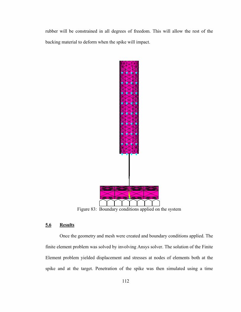
112
rubber will be constrained in all degrees of freedom. This will allow the rest of the
backing material to deform when the spike will impact.
Figure 83: Boundary conditions applied on the system
5.6 Results
Once the geometry and mesh were created and boundary conditions applied. The
finite element problem was solved by involving Ansys solver. The solution of the Finite
Element problem yielded displacement and stresses at nodes of elements both at the
spike and at the target. Penetration of the spike was then simulated using a time
X
Y
Z
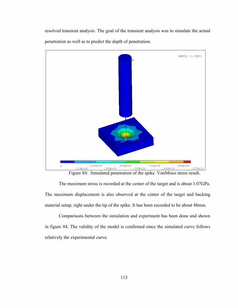
113
resolved transient analysis. The goal of the transient analysis was to simulate the actual
penetration as well as to predict the depth of penetration.
1
MN
MX
X
Y
Z
0
.119E+09.237E+09
.356E+09.474E+09
.593E+09.711E+09
.830E+09.949E+09
.107E+10
ANSYS 11.0SP1
Figure 84: Simulated penetration of the spike. VonMises stress result.
The maximum stress is recorded at the center of the target and is about 1.07GPa.
The maximum displacement is also observed at the center of the target and backing
material setup, right under the tip of the spike. It has been recorded to be about 48mm.
Comparisons between the simulation and experiment has been done and shown
in figure 84. The validity of the model is confirmed since the simulated curve follows
relatively the experimental curve.
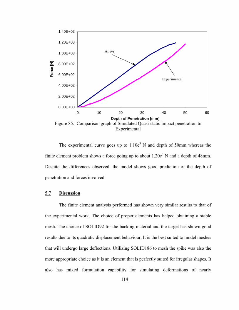
114
Figure 85: Comparison graph of Simulated Quasi-static impact penetration to
Experimental
The experimental curve goes up to 1.10e3 N and depth of 50mm whereas the
finite element problem shows a force going up to about 1.20e3 N and a depth of 48mm.
Despite the differences observed, the model shows good prediction of the depth of
penetration and forces involved.
5.7 Discussion
The finite element analysis performed has shown very similar results to that of
the experimental work. The choice of proper elements has helped obtaining a stable
mesh. The choice of SOLID92 for the backing material and the target has shown good
results due to its quadratic displacement behaviour. It is the best suited to model meshes
that will undergo large deflections. Utilizing SOLID186 to mesh the spike was also the
more appropriate choice as it is an element that is perfectly suited for irregular shapes. It
also has mixed formulation capability for simulating deformations of nearly
0.00E+00
2.00E+02
4.00E+02
6.00E+02
8.00E+02
1.00E+03
1.20E+03
1.40E+03
0 10 20 30 40 50 60Depth of Penetration [mm]
Forc
e [N
]Ansys
Experimental
115
incompressible elastoplastic materials, and fully incompressible hyperelastic materials.
Finally CONTA178 was chosen mostly because it is a 3D node-to-node contact, which
means that it only requires 2 nodes to be defined. The geometries being centered on the
same axis it become more practical to define this type of contact element. Once, the
geometries are meshed, the material properties defined and the boundary conditions set,
the solution is computed through the Ansys solver. In order to compare the simulation
output to the experimental work, the force and the depth of penetration are plotted.
Comparison of the curves shows a good correlation between experimental and finite
element model. Therefore it is possible to utilize the finite element model in order to
predict the force and depth of penetration of a spike test.
116
CHAPTER 6.CONCLUSION
6.1 Summary
The following is the summary of the present investigation:
1. A flexible armor system using a cross-linking fixative (Glutaraldehyde) with
silane, silica and Kevlar has been developed. The new system demonstrates
spike resistance almost 10 times more than that of the traditional PEG-silica-
Kevlar system without any loss of flexibility.
2. An unprecedented material resistance to spike penetration has been observed as
Gluta creates strong chemical bonds between distant pairs of amine groups
present in functionalized silica particles, and Kevlar.
3. Formation of C-N stretches as a result of interaction between Gluta and amide
functional group is responsible for such high resistance to spike. This seems to
happen in presence of Kevlar, but not Spectra which does not have amide
functional groups.
4. When silica particles are replaced in the new system with biodegradable CaCO3
particles, spike performance remains unchanged.
5. Knife performances have been improved significantly by hybridizing Kevlar and
Spectra fabrics – by doing so one has to sacrifice some of the spike resistances,
but overall the new system is superior to previous PEG based systems
117
6. Preliminary work using Finite Element Analysis has been completed to model
the penetration of the spike into the fabric. Geometries, material properties and
boundary conditions have been defined to be as close as possible to the actual
NIJ spike test. The results obtained show a good correlation between the
experimental and the simulation.
6.2 Future Work
1. In our recent studies, we have noticed that Spectra perform well in knife
experiments while Kevlar does that with spike. This prompted us to hybridize
the armor construction with Kevlar and Spectra. However, the exact differences
in the failure mechanisms with knife and spike are not yet fully known. We
intend to perform failure studies with SEM studies and a follow-up numerical
modeling
2. We will also investigate the role of fiber during penetration - as to why Spectra
is good for knife while Kevlar is for spike. This will require design of new
experiments to monitor spike or knife penetration in-situ using a SEM or a high
speed camera
3. Role of fiber in absorbing energy is well known. Although used for ballistic and
puncture applications, the elastic storage energy capacity of commercially
available Spectra and Kevlar fibers are still very low. Nanoscale reinforcement
of these fibers will certainly enhance such capacity. We will reinforce ultra high
molecular polyethylene (UHMWPE, polymer precursor for Spectra fiber) with

118
carbon nanotubes (CNT) through a solution spinning process to increase yield
strength, modulus and fracture strain of the fiber.
.
119
REFERENCES
1 C.T. Nguyen, T. Vu-Khanh, and J. Lara. 2004. "Puncture characterization of rubber membranes." Theoretical and Applied Fracture Mechanics 42: 25-33.
2 "Standard Test Method for Protective Clothing Material Resistance to
Puncture." ASTM Standard F1342-05. 3 L.F. Leslie, J. A. Woods, J.G. Thacker, R.F. Morgan, W. McGregor, and R.F.
Edlich. 1996. "Needle puncture resistance of surgical gloves, finger guards, and glove liners." Journal of Biomedical Materials Research - Applied Biomaterials 33: 41-46.
4 D.C. Erlich, D.A. Shockey, and J.W. Simons. 2003. "Slow penetration of
ballistic fabrics." Textile Research Journal 73, no. 2: 179-184. 5 R.M. Koerner, R.F. Wilson-Fahmy, and D. Narejo. 1996. "Puncture protection
of geomembranes, Part III: Examples." Geosynthetics International 3, no. 5: 655-670.
6 D. Narejo, R.M. Koerner, and R.F. Wilson-Fahmy. 1996. "Puncture protection
of geomembranes, Part II: Experimental." Geosynthetics International 3, no. 5: 629-653.
7 R.F. Wilson-Fahmy, D. Narejo, and R.M. Koerner. 1996. "Puncture protection
of geomembranes, Part I: Theory." Geosynthetics International 3, no. 5: 605-628.
8 T.K. Ghosh. 1998. "Puncture resistance of pre-strained geotextiles and its
relation to uniaxial tensile strain at failure." Geotextiles and Geomembranes 16, no. 5: 293-302.
9 "Standard Test Method for Index Puncture Resistance of Geotextiles,
Geomembranes, and Related Products." ASTM Standard D4833-00e1. 10 J. Lara, D. Turcot, R. Daigle, and J. Boutin. 1996. "New test method to
evaluate the cut resistance of glove materials." ASTM Special Technical Publication 1237: 23-31.
120
11 J. Lara, D. Turcot, R. Daigle, and F. Payot. 1996. "Comparison of two methods to evaluate the resistance of protective gloves to cutting by sharp blades." ASTM Special Technical Publication 1237: 32-42.
12 "Standard Test Method for Measuring Cut Resistance of Materials Used in
Protective Clothing." ASTM Standard F1790-05. 13 J. Lara and S. Masse. 2000. Evaluating the cutting resistance of protective
clothing materials. Proceedings of 1st European Conference on Protective Clothing, Stockholm, Sweden, May 7-10, 2000, edited by Kalev Kuklane and Ingvar Holmer,145-149.
14 H.S. Shin, D.C. Erlich, and D.A. Shockey. 2003. "Test for measuring cut
resistance of yarns." Journal of Materials Science 38: 3603-3610. 15 S.S. Deshmukh and G.H. McKinley. 2003. Magnetorheological suspensions:
Rheology and applications in controllable energy absorption. Proceedings of the Society of Rheology, October 2003.
16 R. Gadow and K. von Niessen. 2006. “Lightweight Ballistic with Additional
Stab Protection Made of Thermally Sprayed Ceramic and Cermet Coatings on Aramide Fabrics.” Journal of Applied Ceramic Technology 3, no. 4: 284-292.
17 S.R. Raghavan and S.A. Khan. 1995. “Shear-induced microstructural changes in
flocculated suspensions of fumed silica,” Journal of Rheology 39, no. 6: 1311-1325.
18 S.R. Raghavan and S.A. Khan. 1997. “Shear-Thickening Response of Fumed
Silica Suspensions under Steady and Oscillatory Shear,” Journal of Colloid and Interface Science 185: 57-67.
19 B.J. Maranzano and N.J. Wagner. 2001. “The effects of particle size on
reversible shear thickening of concentrated colloidal dispersions,” Journal of Chemical Physics 114, no. 23: 10514-10527.
20 Y.S. Lee and N.J. Wagner. 2003. “Dynamic properties of shear thickening
colloidal suspensions,” Rheology Acta 42, no. 3: 199-208. 21 Y.S. Lee, Wetzel, E.D. and N.J. Wagner. 2003. “The ballistic impact
characteristics of Kevlar® woven fabrics impregnated with a colloidal shear thickening fluid,” Journal of Materials Science 38, no. 13: 2825-2833.
121
22 Y.S. Lee, E.D. Wetzel, R.G. Egres Jr., and N.J. Wagner. 2002. Advanced Body Armor Utilizing Shear Thickening Fluids. Proceedings of the 23rd Army Science Conference, 2002.
23 E.D. Wetzel, Y.S. Lee, R.G. Egres, K.M. Kirkwood, J.E. Kirkwood, and N.J.
Wagner. 2004. Proceedings of NUMIFORM, 2004. 24 R.G. Egres, Y.S. Lee, J.E. Kirkwood, K.M. Kirkwood, E.D. Wetzel and N.J.
Wagner. 2003. Proceedings of the 14th International Conference on Composite Materials, July 2003.
25 R.G. Egres Jr., M.J. Decker, C.J. Halbach, Y.S. Lee, J.E. Kirkwood, K.M.
Kirkwood, E.D. Wetzel, N.J. Wagner. 2004. Stab Resistance of Shear Thickening Fluid (STF)-Kevlar Composites for Body Armor Applications. In Proceedings of the 24th Army Science Conference, Orlando, Florida, November 29-December 2, 2004.
26 V.B.C. Tan, T.E. Tay and W.K. Teo. 2005. “Strengthening fabric armour with
silica colloidal suspensions,” International Journal of Solids and Structures 42: 1561-1576.
27 S.L. Phoenix and P.K. Porwal. 2003. “A new membrane for the ballistic impact
response and V50 performance of multi-ply fibrous systems,” International Journal of Solids and Structures 40: 6723-6765.
28 P.K. Porwal and S.L. Phoenix. 2005. “Modeling system effects in ballistic
impact into multi-layered fibrous materials for soft body armor,” International Journal of Fracture 135: 217-249.
29 W.J. Taylor and J.R. Vinson. 1989. “Modeling Ballistic Impact into Flexible
Materials,” American Institute of Aeronautics and Astronautics 28, no. 12: 2098-2103.
30 B. Gu. 2003. “Analytical modeling for the ballistic perforation of planar plain-
woven fabric target by projectile,” Composites: Part B 34: 361-371. 31 S. Luo and T. Chou. 1990, “Finite Deformation of Flexible Composites,”
Proceedings of the Royal Society of London 429, no.1877: 569-586. 32 G. Stylios and Y.M. Xu. 1995. “An Investigation of the Penetration Force
Profile of the Sewing Machine Needle Point,” Journal of Textile Instruments 86, no. 1: 148-163.
122
33 S. Suresh, A.E. Giannakopoulos and J. Alcala. 1997. “Spherical Indentation of Compositionally Graded Materials: Theory and Experiments,” Acta Metallurgica 45, no.4: 1307-1321.
34 S. Suresh and A.E. Giannakopoulos. 1998. “A New Method for Estimating
Residual Stresses by Instrumented Sharp Indentation,” Acta Metallurgica 46, no. 16: 5755-5767.
35 A.E. Giannakopoulos and S. Suresh. 1999. “Determination of Elastoplastic
Properties by Instrumented Sharp Indentation,” Scripta Materialia 40, no. 10: 1191-1198.
36 E.W. Andrews; A.E. Giannakopoulos; E. Plisson, and S. Suresh: 2002.
“Analysis of the impact of a sharp indenter,” International Journal of Solids and Structures 39, no. 2: 281-295.
37 C. Nathaniel, H. Mahfuz, V. Rangari, A. Ashfaq and S. Jeelani. 2005.
“Fabrication and Mechanical Characterization of Carbon/Epoxy Nanocomposites,” Composite Structures 67: 115-124.
38 H. Mahfuz, A. Adnan, V.K. Rangari, M.M. Hasan, S. Jeelani, W.J. Wright and
S.J. DeTeresa. 2006. “Enhancement of Strength and Stiffness of Nylon 6 Filaments through Carbon Nanotubes Reinforcements,” Applied Physics Letters 88, no. 1.
39 R. Rodgers, H. Mahfuz, V. Rangari, N. Chisholm, and S. Jeelani. 2005.
“Infusion of Nanoparticle into SC-15 Epoxy; an Investigation of Thermal and Mechanical Response,” Macromolecular Materials & Engineering 290, no. 5: 423-429.
40 V.M. Harik and M. Salas, eds. 2003. Trends in Nanoscale Mechanics: Analysis
of Nanostructured Materials and Multi-Scale Modeling. Dordrecht, The Netherlands: Kluwer Academic Publishers.
41 M.W. Urban and E.M. Salazar-Rojas. 1988. “Ultrasonic PTC Modification of
poly(vinylidene fluoride) Surfaces and Their Characterization,” Macromolecules 21: 372-378.
42 Hesheng Xia, Qi Wang, and Guihua Qiu. 2003. “Polymer-Encapsulated Carbon
Nanotubes Prepared through Ultrasonically Initiated In Situ Emulsion Polymerization, Chemistry of Materials 15, no. 20: 3879-3886
43 Toshio Sato, Takeyoshi Uchida, Akito Endo, Shinichi Takeuchi, Naimu
Kuramochi and Noricmichi Kawashima. 2002. Study on dispersion and

123
surface modification of diamond powders by ultrasound exposure. In Proceedings of the IEEE Ultrasonics Symposium 1: 521-525.
44 S. Ramesh, Y. Koltypin and A. Gedanken. 1997. “Ultrasound driven
aggregation and surface silanol modification in amorphous silica microspheres,” Journal of Materials Research 12, no. 12: 3271-3277.
45 R. Birringer and H. Gleiter. 1998. In: R.W. Cahn, Editor, Advance in Materials
Science, Encyclopedia of materials science and engineering, Volume 1. Pergamon Press, Oxford: 339.
46 H. Gleiter. 1989. “Nanocrystalline Materials,” Progress in Materials Science 33:
223-315. 47 R. Dagani. 1992. “Nanostructural materials promise to advance range of
technologies,” Chemical Engineering & News: 18-24. 48 Hyunsook Kim, Myoung-soon Kim, Hyesun Paik, Yeon-Sook Chung, In Seok
Hong and Junghun Suh. “Effective Artificial Proteases Synthesized by Covering Silica Gel with Aldehyde and Various Other Organic Groups”. Bioorganic & Medicinal Chemistry Letters 12 (2002) 3247–3250
49 2001. Kevlar Home Page. http://www.dupont.com/kevlar/. 50 Spectra Home Page, http://www51.honeywell.com/sm/afc/products-
details/fiber.html 51 Selection and Application Guide to Personal Body Armor, NIJ Guide – 100-01,
November 2001. 52 A.P. Smith and H. Ade. 1996. “Quantitative orientational analysis of a
polymeric material (Kevlar® fibers) with x-ray microspectroscopy,” Applied Physics Letters 69, no. 25: 38833-3835.
53 H. Ade and B. Hsiao. 1993. “X-ray Linear Dichroism Microscopy,” Science
262, no. 5138: 1427-1429. 54 MSDS: Sigma-Aldrich – Polyethylene Glycol av. Mol. Wt. 200, P3015. 55 Sigma Aldrich Product Information, Silica nanopowder 637238. 56 H. Mahfuz. 2006. “Functionalized nanoparticles and their influence on the
properties of nanocomposites,” Presented at the Annual Review meeting for ONR, Washington, D.C.
124
57 Gelest, “Gelest Silane Coupling Agents: Connecting Across Boundaries,” Gelest, Inc., 2006.
58 Sonics, “High Intensity Ultrasound Liquid Processors,” Sonics & Materials,
Inc., 2004. 59 K. Rice. 2000. National Institute of Justice: Stab Resistance of Personal Body
Armor: NIJ Standard – 0115.0, September 2000. 60 John Coates. 2000. “Interpretation of Infrared Spectra, A Practical Approach,”
Encyclopedia of Analytical Chemistry. R.A. Meyers. Chichester: John Wiley & Sons Ltd: 10815-10837.
61 “Department of Defense Test Method Standard: V50 Ballistic Test for Armor,” MIL-STD-662F, 1997.
62 National Institute of Justice: Ballistic Resistance of Personal Body Armor: NIJ
Standard – 0101.4, Revision A, June 2001. 63 Floria Clements, “development of flexible puncture resistant materials system
using nanoparticles”. College of Engineering and Computer Science, 2007
64 Lee et Al, “The ballistic impact characteristics of Kevlar woven fabrics
impregnated with a colloidal shear thickening fluid”. Journal of Materials Science 38 (2003) 2825 – 2833
65 H.Mahfuz, V.Lambert, P.Bordner. V.Rangari “Development of Stab Resistant
Body Armor Using Silated SiO2 Nanoparticles Dispersed into Glutaraldehyde”. NSTI 2008 paper 788
66 NIJ Standard 0115.00 “Stab resistance of personal body armor” National
Institute of Justice, Sept 2000. 67 C.T.Sun, V.Dong, ARO Report 2007
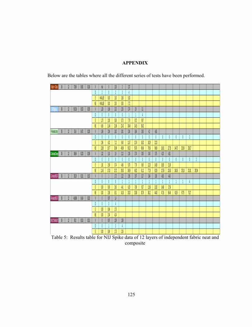
125
APPENDIX
Below are the tables where all the different series of tests have been performed.
Nylon + Gluta 36 12 73,86 0,651 0,318 V n/a 0 1,35 2 2,37D 2 0 2 3 4E #VALUE! 0,00 1,63 3,58 5,03
NE #VALUE! 0,00 2,50 5,50 7,72SPC/gluta 36 12 59,316 0,523 0,255 V 1,28 1,68 2,32 2,35 2,74 2,9 3,1
D 0 0 0 0 1 1 4E 1,70 2,93 5,58 5,73 7,79 8,72 9,97
NE 6,65 11,46 21,86 22,42 30,48 34,15 39,02R-Kevlar/comp 36 12 53,4 0,471 0,230 V 1,69 2,04 2,62 3,01 3,34 3,64 3,93 4,2 4,63
D 0 0 0 0 0 0 0 0 0 0 0 0 0 2E 2,96 4,32 7,12 9,40 11,57 13,74 16,02 18,29 22,23
NE 12,88 18,77 30,96 40,86 50,32 59,76 69,66 79,56 96,69 116,81 127,55 144,75 210,56 238,27C-Kevlar/Comp 36 12 36,66 0,323 0,158 V 1,32 1,61 1,9 2,12 2,36 2,74 3,05 3,43 3,75 4,23 4,51
D 0 0 0 0 0 0 0 0 0 0 0 0 0 0 2E 1,81 2,69 3,74 4,66 5,78 7,79 9,65 12,20 14,58 18,55 21,09
NE 11,45 17,03 23,72 29,53 36,59 49,32 61,12 77,29 92,39 117,55 133,63 160,36 178,18 231,81 292,94C-Kevlar/NEAT 36 12 35,28 0,311 0,152 V 0 1 1,72 2,22 2,65 2,97 3,27 3,64 3,93 4,05 4,43
D 0 0 0 1 1 1 1 1 1 1 1 1 1 4E 0,00 0,90 2,65 4,41 6,29 7,89 9,57 11,86 13,82 14,68 17,56
NE 0,00 2,88 8,51 14,18 20,20 25,38 30,76 38,12 44,43 47,19 56,46 61,59 67,75 75,27R-Kevlar/NEAT 36 12 46,896 0,414 0,202 V 0 0,97 1,4
D 0 3 4E 0,00 0,84 1,75
NE 0,00 2,04 4,24SPECTRA/NEAT 36 12 58,2 0,513 0,251 V 0 0,97 1,39 1,59
D 0 1 3 4E 0,00 0,84 1,73 2,26
Table 5: Results table for NIJ Spike data of 12 layers of independent fabric neat and composite

126
[1]C-Kevlar/[11]SPC/c 36 12 57.854 0.510 0.249 V 0 1.01 1.38 1.78 1.98 2.2 2.34 2.68 2.8 3.01 3.12 3.29D 0 0 0 0 1 1 2 2 3 3 3 4E 0.00 0.91 1.70 2.84 3.51 4.33 4.90 6.43 7.02 8.11 8.71 9.69
NE 0.00 1.79 3.34 5.56 6.88 8.49 9.61 12.60 13.75 15.89 17.08 18.99[2]C-Kevlar/[10]SPC/c 36 12 55.342 0.488 0.238 V 0 1 1.41 1.74 1.97 2.22 2.36 2.59 2.8 3.12
D 0 0 0 0 1 1 2 3 3 4E 0.00 0.90 1.78 2.71 3.47 4.41 4.98 6.00 7.02 8.71
NE 0.00 1.83 3.65 5.55 7.12 9.04 10.21 12.30 14.38 17.85[3]C-Kevlar/[9]SPC/c 36 12 53.793 0.474 0.232 V 0 1 1.42 1.74 1.93 2.16 2.39 2.57 2.77 2.97
D 0 0 0 0 1 2 3 3 3 4E 0.00 0.90 1.80 2.71 3.33 4.18 5.11 5.91 6.87 7.89
NE 0.00 1.89 3.80 5.71 7.03 8.80 10.78 12.46 14.48 16.64[4]C-Kevlar/[8]SPC/c 36 12 52.244 0.461 0.225 V 0 1.03 1.42 1.72 1.95 2.2 2.39 2.51 2.77 3.01
D 0 0 0 1 1 2 3 3 3 4E 0.00 0.95 1.80 2.65 3.40 4.33 5.11 5.64 6.87 8.11
NE 0.00 2.06 3.92 5.75 7.39 9.40 11.10 12.24 14.91 17.60[5]C-Kevlar/[7]SPC/c 36 12 50.695 0.447 0.218 V 0 0.99 1.43 1.72 1.97 2.2 2.39 2.65 2.8
D 0 0 1 2 2 2 3 3 4E 0.00 0.88 1.83 2.65 3.47 4.33 5.11 6.29 7.02
NE 0.00 1.96 4.09 5.92 7.77 9.69 11.44 14.06 15.70[6]C-Kevlar/[6]SPC/c 36 12 49.146 0.433 0.212 V 0 1 1.45 1.77 1.98 2.22 2.41 2.62
D 0 0 1 2 2 3 3 4E 0.00 0.90 1.88 2.80 3.51 4.41 5.20 6.14
NE 0.00 2.07 4.34 6.47 8.10 10.18 11.99 14.18[7]C-Kevlar/[5]SPC/c 36 12 47.597 0.420 0.205 V 0 1.01 1.43 1.73 1.98 2.22 2.39 2.62
D 0 1 2 2 3 3 3 4E 0.00 0.91 1.83 2.68 3.51 4.41 5.11 6.14
NE 0.00 2.18 4.36 6.38 8.36 10.51 12.18 14.64[8]C-Kevlar/[4]SPC/c 36 12 46.048 0.406 0.198 V 0 1 1.41 1.72 1.98 2.21 2.41
D 0 1 2 2 3 3 4E 0.00 0.90 1.78 2.65 3.51 4.37 5.20
NE 0.00 2.20 4.38 6.52 8.64 10.76 12.80[9]C-Kevlar/[3]SPC/c 36 12 44.499 0.392 0.192 V 0 0.98 1.39 1.75 2 2.14
D 0 1 2 3 3 4E 0.00 0.86 1.73 2.74 3.58 4.10
NE 0.00 2.19 4.41 6.98 9.12 10.44[10]C-Kevlar/[2]SPC/c 36 12 42.95 0.379 0.185 V 0 0.97 1.38 1.75 1.93 2.18
D 0 1 2 3 3 4E 0.00 0.84 1.70 2.74 3.33 4.25
NE 0.00 2.22 4.50 7.24 8.80 11.23[11]C-Kevlar/[1]SPC/c 36 12 36.66 0.323 0.158 V 0 1.01 1.41 1.74 1.97
D 0 1 2 3 4E 0.00 0.91 1.78 2.71 3.47
NE 0.00 2.82 5.50 8.38 10.74
Table 6: Results table for NIJ Knife data of 12 layers combination of reinforced
Correctional Kevlar and Spectra

127
[1]C-K/[11]SPC/C 36 12 57,854 0,510 0,249 V 0 1,02 1,4 1,65 1,97 2,24 2,37 2,46 2,74 3,01 3,21 3,64 4,975 54,725D 0 0 0 0 0 0 0 0 0 1 1 4E 0,00 0,93 1,75 2,44 3,47 4,49 5,03 5,42 6,72 8,11 9,22 11,86
NE 0,00 1,83 3,44 4,78 6,81 8,80 9,85 10,62 13,17 15,89 18,08 23,24[2]C-K/[10]SPC/c 36 12 55,342 0,488 0,238 V 0 1,03 1,5 1,8 2,07 2,32 2,58 2,8 2,97 3,01 3,38
D 0 0 0 0 0 0 0 0 0 1 4E 0,00 0,95 2,01 2,90 3,83 4,82 5,96 7,02 7,89 8,11 10,22
NE 0,00 1,95 4,13 5,94 7,86 9,87 12,21 14,38 16,18 16,62 20,95[3]C-K/[9]SPC/c 36 12 53,793 0,474 0,232 V 0 1,15 1,65 2,24 2,57 2,71 2,94 3,05 3,25
D 0 0 0 0 0 1 1 1 4E 0,00 1,18 2,44 4,49 5,91 6,57 7,74 8,33 9,45
NE 0,00 2,50 5,14 9,47 12,46 13,86 16,31 17,55 19,93[4]C-K/[8]SPC/c 36 12 52,244 0,461 0,225 V 0 0,95 1,68 2,14 2,59 2,77 2,94 3,05 3,21 3,48 3,53 3,75
D 0 0 0 0 0 0 0 0 0 0 0 4E 0,00 0,81 2,53 4,10 6,00 6,87 7,74 8,33 9,22 10,84 11,15 12,59
NE 0,00 1,75 5,48 8,90 13,03 14,91 16,79 18,07 20,02 23,53 24,21 27,32[5]C-K/[7]SPC/c 36 12 50,695 0,447 0,218 V 0 0,95 1,68 2,2 2,49 2,94 3,25 3,48 3,58 3,69 4,06
D 0 0 0 0 0 0 0 0 0 0 4E 0,00 0,81 2,53 4,33 5,55 7,74 9,45 10,84 11,47 12,19 14,75
NE 0,00 1,81 5,65 9,69 12,41 17,30 21,15 24,24 25,66 27,26 33,00[6]C-K/[6]SPC/c 36 12 49,146 0,433 0,212 V 0 1 1,68 2,2 2,54 2,86 3,25 3,58 3,69 3,93
D 0 0 0 0 0 0 0 0 0 4E 0,00 0,90 2,53 4,33 5,77 7,32 9,45 11,47 12,19 13,82
NE 0,00 2,07 5,83 10,00 13,32 16,89 21,81 26,47 28,12 31,90[7]C-K/[5]SPC/c 36 12 47,597 0,420 0,205 V 0 0,97 1,73 2,16 2,5 2,97 3,29 3,53 3,75 3,87 4,02 4,13 4,2 4,38
D 0 0 0 0 0 0 0 0 0 0 0 0 0 4E 0,00 0,84 2,68 4,18 5,59 7,89 9,69 11,15 12,59 13,40 14,46 15,27 15,79 17,17
NE 0,00 2,01 6,38 9,95 13,33 18,81 23,08 26,57 29,99 31,94 34,46 36,37 37,61 40,91[8]C-K/[4]SPC/c 36 12 46,048 0,406 0,198 V 0 0,96 1,69 2,16 2,62 2,94 3,29 3,48 3,87 4,2
D 0 0 0 0 0 0 0 0 0 4E 0,00 0,82 2,56 4,18 6,14 7,74 9,69 10,84 13,40 15,79
NE 0,00 2,03 6,29 10,28 15,13 19,05 23,86 26,69 33,01 38,88[9]C-K/[3]SPC/c 36 12 44,499 0,392 0,192 V 0 1,01 1,66 2,1 2,57 2,94 3,25 3,64 3,87 4,13 4,28 4,4
D 0 0 0 0 0 0 0 0 0 0 0 0E 0,00 0,91 2,47 3,95 5,91 7,74 9,45 11,86 13,40 15,27 16,39 17,33
NE 0,00 2,33 6,28 10,06 15,06 19,71 24,09 30,22 34,16 38,90 41,78 44,16[10]C-K/[2]SPC/c 36 12 42,95 0,379 0,185 V 0 0,97 1,69 2,14 2,57 3,05 3,25 3,64 3,88 4,11 4,37
D 0 0 0 0 0 0 0 0 0 0 0E 0,00 0,84 2,56 4,10 5,91 8,33 9,45 11,86 13,47 15,12 17,09
NE 0,00 2,22 6,75 10,82 15,61 21,98 24,96 31,31 35,57 39,92 45,13[11]C-K/[1]SPC/c 36 12 36,66 0,323 0,158 V 0 0,96 1,67 2,1 2,57 3,02 3,21 3,65 3,9 4,08 4,36
D 0 0 0 0 0 0 0 0 0 0 0E 0,00 0,82 2,50 3,95 5,91 8,16 9,22 11,92 13,61 14,90 17,01
NE 0,00 2,55 7,72 12,21 18,29 25,25 28,53 36,88 42,11 46,08 52,63
Table 7: Results table for NIJ Spike data of 12 layers combination of reinforced
Correctional Kevlar and Spectra
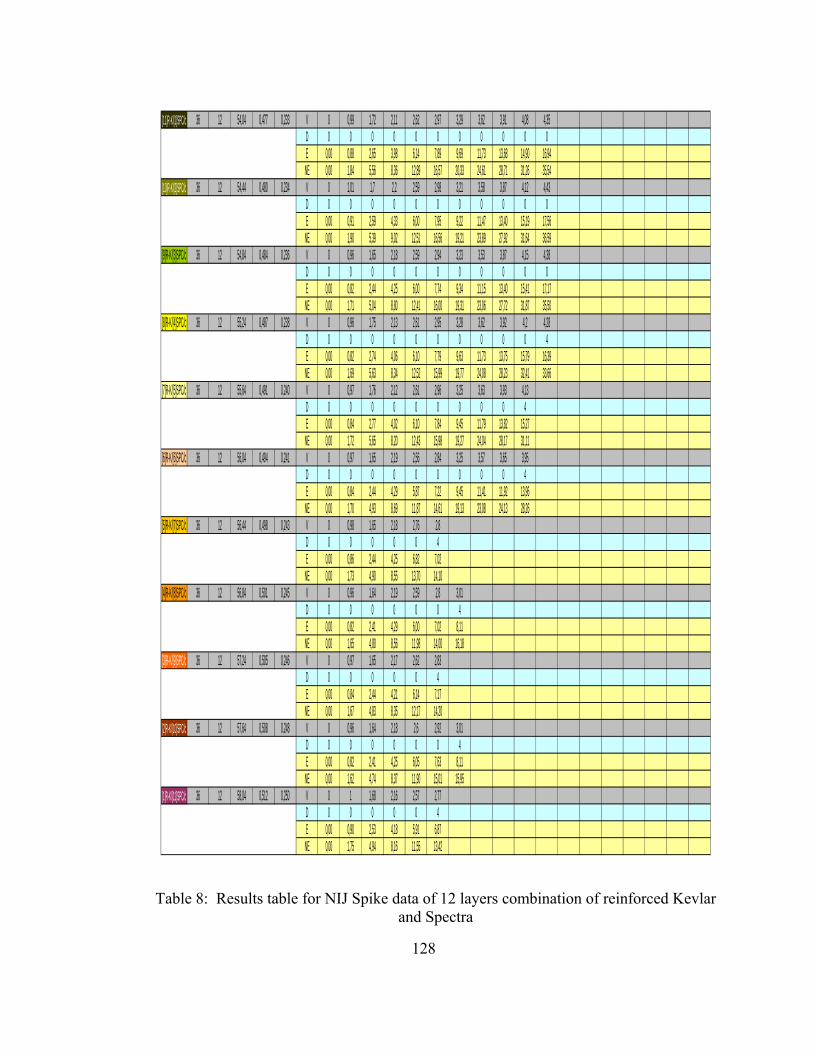
128
[11]R-K/[1]SPC/c 36 12 54,04 0,477 0,233 V 0 0,99 1,72 2,11 2,62 2,97 3,29 3,62 3,91 4,08 4,35
D 0 0 0 0 0 0 0 0 0 0 0E 0,00 0,88 2,65 3,98 6,14 7,89 9,69 11,73 13,68 14,90 16,94
NE 0,00 1,84 5,56 8,36 12,89 16,57 20,33 24,61 28,71 31,26 35,54[10]R-K/[2]SPC/c 36 12 54,44 0,480 0,234 V 0 1,01 1,7 2,2 2,59 2,98 3,21 3,58 3,87 4,12 4,43
D 0 0 0 0 0 0 0 0 0 0 0E 0,00 0,91 2,59 4,33 6,00 7,95 9,22 11,47 13,40 15,19 17,56
NE 0,00 1,90 5,39 9,02 12,51 16,56 19,21 23,89 27,92 31,64 36,59[9]R-K/[3]SPC/c 36 12 54,84 0,484 0,236 V 0 0,96 1,65 2,18 2,59 2,94 3,23 3,53 3,87 4,15 4,38
D 0 0 0 0 0 0 0 0 0 0 0E 0,00 0,82 2,44 4,25 6,00 7,74 9,34 11,15 13,40 15,41 17,17
NE 0,00 1,71 5,04 8,80 12,41 16,00 19,31 23,06 27,72 31,87 35,50[8]R-K/[4]SPC/c 36 12 55,24 0,487 0,238 V 0 0,96 1,75 2,13 2,61 2,95 3,28 3,62 3,92 4,2 4,28
D 0 0 0 0 0 0 0 0 0 0 4E 0,00 0,82 2,74 4,06 6,10 7,79 9,63 11,73 13,75 15,79 16,39
NE 0,00 1,69 5,63 8,34 12,52 15,99 19,77 24,08 28,23 32,41 33,66[7]R-K/[5]SPC/c 36 12 55,64 0,491 0,240 V 0 0,97 1,76 2,12 2,61 2,96 3,25 3,63 3,93 4,13
D 0 0 0 0 0 0 0 0 0 4E 0,00 0,84 2,77 4,02 6,10 7,84 9,45 11,79 13,82 15,27
NE 0,00 1,72 5,65 8,20 12,43 15,98 19,27 24,04 28,17 31,11[6]R-K/[6]SPC/c 36 12 56,04 0,494 0,241 V 0 0,97 1,65 2,19 2,56 2,84 3,25 3,57 3,65 3,95
D 0 0 0 0 0 0 0 0 0 4E 0,00 0,84 2,44 4,29 5,87 7,22 9,45 11,41 11,92 13,96
NE 0,00 1,70 4,93 8,69 11,87 14,61 19,13 23,08 24,13 28,26[5]R-K/[7]SPC/c 36 12 56,44 0,498 0,243 V 0 0,98 1,65 2,18 2,76 2,8
D 0 0 0 0 0 4E 0,00 0,86 2,44 4,25 6,82 7,02
NE 0,00 1,73 4,90 8,55 13,70 14,10[4]R-K/[8]SPC/c 36 12 56,84 0,501 0,245 V 0 0,96 1,64 2,19 2,59 2,8 3,01
D 0 0 0 0 0 0 4E 0,00 0,82 2,41 4,29 6,00 7,02 8,11
NE 0,00 1,65 4,80 8,56 11,98 14,00 16,18[3]R-K/[9]SPC/c 36 12 57,24 0,505 0,246 V 0 0,97 1,65 2,17 2,62 2,83
D 0 0 0 0 0 4E 0,00 0,84 2,44 4,21 6,14 7,17
NE 0,00 1,67 4,83 8,35 12,17 14,20[2]R-K/[10]SPC/c 36 12 57,64 0,508 0,248 V 0 0,96 1,64 2,18 2,6 2,92 3,01
D 0 0 0 0 0 0 4E 0,00 0,82 2,41 4,25 6,05 7,63 8,11
NE 0,00 1,62 4,74 8,37 11,90 15,01 15,95[1]R-K/[11]SPC/c 36 12 58,04 0,512 0,250 V 0 1 1,68 2,16 2,57 2,77
D 0 0 0 0 0 4E 0,00 0,90 2,53 4,18 5,91 6,87
NE 0,00 1,75 4,94 8,16 11,55 13,42
Table 8: Results table for NIJ Spike data of 12 layers combination of reinforced Kevlar
and Spectra
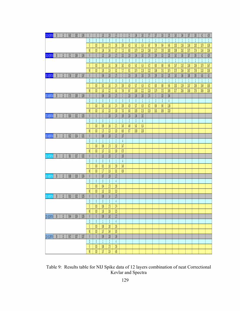
129
[11]C-K/[1]SPC/N 36 12 56,92 0,502 0,245 V 0 1,02 1,39 1,72 2 2,2 2,46 2,62 2,77 2,97 3,16 3,25 3,43 3,64 3,87 3,93 4,2 4,28
D 0 0 0 0 0 0 0 0 1 1 1 1 1 1 1 1 1 1E 0,00 0,93 1,73 2,65 3,58 4,33 5,42 6,14 6,87 7,89 8,94 9,45 10,53 11,86 13,40 13,82 15,79 16,39
NE 0,00 1,86 3,45 5,27 7,13 8,63 10,79 12,24 13,68 15,73 17,80 18,83 20,98 23,62 26,70 27,54 31,45 32,66[10]C-K/[2]SPC/N 36 12 57,2 0,504 0,246 V 0 1,02 1,34 1,73 2,01 2,19 2,46 2,62 2,74 2,99 3,15 3,25 3,42 3,65 3,87 3,95 4,2 4,29
D 0 0 0 0 0 0 0 0 1 1 1 1 1 1 1 1 1 1E 0,00 0,93 1,61 2,68 3,62 4,29 5,42 6,14 6,72 8,00 8,88 9,45 10,47 11,92 13,40 13,96 15,79 16,47
NE 0,00 1,85 3,19 5,31 7,17 8,51 10,74 12,18 13,32 15,86 17,61 18,74 20,75 23,64 26,57 27,68 31,30 32,65[9]C-K/[3]SPC/N 36 12 57,48 0,507 0,247 V 0 0,96 1,35 1,75 2 2,19 2,45 2,63 2,74 2,99 3,15 3,25 3,43 3,66 3,88 3,95 4,16 4,3
D 0 0 0 0 0 0 0 1 1 1 1 1 1 1 1 1 1 1E 0,00 0,82 1,63 2,74 3,58 4,29 5,37 6,19 6,72 8,00 8,88 9,45 10,53 11,99 13,47 13,96 15,49 16,55
NE 0,00 1,63 3,22 5,41 7,06 8,47 10,60 12,21 13,26 15,79 17,52 18,65 20,77 23,65 26,58 27,55 30,56 32,65[8]C-K/[4]SPC/N 36 12 57,76 0,509 0,249 V 0 0,96 1,35 1,75 2 2,19 2,45 2,63 2,74 3 3,25 3,64
D 0 0 0 0 0 0 0 1 1 3 3 4E 0,00 0,82 1,63 2,74 3,58 4,29 5,37 6,19 6,72 8,06 9,45 11,86
NE 0,00 1,62 3,20 5,38 7,03 8,43 10,55 12,15 13,19 15,81 18,56 23,28[7]C-K/[5]SPC/N 36 12 58,04 0,512 0,250 V 0 1 1,36 1,74 1,95 2,24 2,46 2,62
D 0 0 1 1 1 2 3 4E 0,00 0,90 1,66 2,71 3,40 4,49 5,42 6,14
NE 0,00 1,75 3,23 5,29 6,65 8,77 10,58 12,00[6]C-K/[6]SPC/N 36 12 58,32 0,514 0,251 V 0 0,98 1,38 1,71 1,97
D 0 1 1 2 4E 0,00 0,86 1,70 2,62 3,47
NE 0,00 1,67 3,31 5,09 6,75[5]C-K/[7]SPC/N 36 12 58,6 0,517 0,252 V 0 1,01 1,35 1,7 1,95
D 0 0 0 1 4E 0,00 0,91 1,63 2,59 3,40
NE 0,00 1,77 3,16 5,01 6,59[4]C-K/[8]SPC/N 36 12 58,88 0,519 0,254 V 0 0,97 1,39 1,72
D 0 0 3 4E 0,00 0,84 1,73 2,65
NE 0,00 1,62 3,33 5,10[3]C-K/[9]SPC/N 36 12 59,16 0,522 0,255 V 0 0,98 1,4 1,75
D 0 0 3 4E 0,00 0,86 1,75 2,74
NE 0,00 1,65 3,36 5,25[2]C-K[10]SPC/N 36 12 59,44 0,524 0,256 V 0 0,99 1,42 1,72
D 0 1 3 4E 0,00 0,88 1,80 2,65
NE 0,00 1,67 3,44 5,05[1]C-K/[11]SPC/N 36 12 59,72 0,527 0,257 V 0 0,99 1,38 1,69
D 0 1 2 4E 0,00 0,88 1,70 2,56
NE 0,00 1,67 3,24 4,85
Table 9: Results table for NIJ Spike data of 12 layers combination of neat Correctional
Kevlar and Spectra

130
[1]R-K/[11]SPC/N 36 12 61,613 0,543 0,265 V 0 0,98 1,38 1,73D 0 0 2 4E 0,00 0,86 1,70 2,68
NE 0,00 1,58 3,14 4,93[2]R-K/[10]SPC/N 36 12 61,186 0,540 0,263 V 0 0,99 1,37 1,65
D 0 1 3 4E 0,00 0,88 1,68 2,44
NE 0,00 1,63 3,11 4,52[3]R-K/[9]SPC/N 36 12 60,759 0,536 0,262 V 0 1,02 1,4 1,72
D 0 1 3 4E 0,00 0,93 1,75 2,65
NE 0,00 1,74 3,27 4,94[4]R-K/[8]SPC/N 36 12 60,332 0,532 0,260 V 0 1 1,42 1,72
D 0 1 3 4E 0,00 0,90 1,80 2,65
NE 0,00 1,68 3,39 4,98[5]R-K/[7]SPC/N 36 12 59,905 0,528 0,258 V 0 0,96 1,38 1,7
D 0 1 3 4E 0,00 0,82 1,70 2,59
NE 0,00 1,56 3,23 4,90[6]R-K/[6]SPC/N 36 12 59,478 0,525 0,256 V 0 0,99 1,41 1,72
D 0 1 3 4E 0,00 0,88 1,78 2,65
NE 0,00 1,67 3,39 5,05[7]R-K/[5]SPC/N 36 12 59,051 0,521 0,254 V 0 0,99 1,42
D 0 2 4E 0,00 0,88 1,80
NE 0,00 1,68 3,47[8]R-K/[4]SPC/N 36 12 58,624 0,517 0,252 V 0 0,99 1,4
D 0 2 4E 0,00 0,88 1,75
NE 0,00 1,70 3,39[9]R-K/[3]SPC/N 36 12 58,197 0,513 0,251 V 0 0,99 1,41
D 0 3 4E 0,00 0,88 1,78
NE 0,00 1,71 3,47[10]R-K/[2]SPC/N 36 12 57,77 0,509 0,249 V 0 0,99 1,41
D 0 3 4E 0,00 0,88 1,78
NE 0,00 1,72 3,49[11]R-K/[1]SPC/N 36 12 57,343 0,506 0,247 V 0 1,02 1,42
D 0 3 4E 0,00 0,93 1,80
NE 0,00 1,84 3,57
Table 10: Results table for NIJ Spike data of 12 layers combination of neat Kevlar and
Spectra

131
Nylon + Gluta 36 12 73,86 0,651 0,318 V 0 0 1,35 2 2,37D 0 0 2 3 4E 0,00 0,00 1,63 3,58 5,03
NE 0,00 0,00 2,50 5,50 7,72Spectra/Gluta/SiO2 36 12 58,86 0,519 0,253 V 0 1,35 1,92 2,39 2,68 3,15 3,35
D 0 0 0 1 2 3 4E 0,00 1,63 3,30 5,11 6,43 8,88 10,04
NE 0,00 3,14 6,36 9,85 12,38 17,11 19,35R-Kevlar/Gluta/Si02 36 12 50,484 0,445 0,217 V 0 1,35 1,67 1,75 1,95
D 0 1 2 3 4E 0,00 1,63 2,50 2,74 3,40
NE 0,00 3,66 5,61 6,16 7,64C-Kevlar/Gluta/Si02 36 12 39,852 0,351 0,172 V 0 1 1,43 1,74 1,97
D 0 1 2 3 4E 0,00 0,90 1,83 2,71 3,47
NE 0,00 2,55 5,21 7,71 9,88C-Kevlar/NEAT 36 12 35,28 0,311 0,152 V 0 1,01 1,41 1,56
D 0 2 3 4E 0,00 0,91 1,78 2,18
NE 0,00 2,93 5,72 7,00R-Kevlar/NEAT 36 12 46,896 0,414 0,202 V 0 1,01 1,4 1,74
D 0 2 3 4E 0,00 0,91 1,75 2,71
NE 0,00 2,21 4,24 6,55SPECTRA/NEAT 36 12 58,2 0,513 0,251 V 0 1 1,42 1,7 1,98 2,18 2,41 2,59 2,9
D 0 1 2 2 3 3 3 3 4E 0,00 0,90 1,80 2,59 3,51 4,25 5,20 6,00 7,53
NE 0,00 1,74 3,52 5,04 6,84 8,29 10,13 11,70 14,67 Table 11: Results table for NIJ Knife data of 12 layers of independent fabric neat and
composite

132
[1]C-Kevlar/[11]SPC/c 36 12 57,854 0,510 0,249 V 0 1,01 1,38 1,78 1,98 2,2 2,34 2,68 2,8 3,01 3,12 3,29D 0 0 0 0 1 1 2 2 3 3 3 4E 0,00 0,91 1,70 2,84 3,51 4,33 4,90 6,43 7,02 8,11 8,71 9,69
NE 0,00 1,79 3,34 5,56 6,88 8,49 9,61 12,60 13,75 15,89 17,08 18,99[2]C-Kevlar/[10]SPC/c 36 12 55,342 0,488 0,238 V 0 1 1,41 1,74 1,97 2,22 2,36 2,59 2,8 3,12
D 0 0 0 0 1 1 2 3 3 4E 0,00 0,90 1,78 2,71 3,47 4,41 4,98 6,00 7,02 8,71
NE 0,00 1,83 3,65 5,55 7,12 9,04 10,21 12,30 14,38 17,85[3]C-Kevlar/[9]SPC/c 36 12 53,793 0,474 0,232 V 0 1 1,42 1,74 1,93 2,16 2,39 2,57 2,77 2,97
D 0 0 0 0 1 2 3 3 3 4E 0,00 0,90 1,80 2,71 3,33 4,18 5,11 5,91 6,87 7,89
NE 0,00 1,89 3,80 5,71 7,03 8,80 10,78 12,46 14,48 16,64[4]C-Kevlar/[8]SPC/c 36 12 52,244 0,461 0,225 V 0 1,03 1,42 1,72 1,95 2,2 2,39 2,51 2,77 3,01
D 0 0 0 1 1 2 3 3 3 4E 0,00 0,95 1,80 2,65 3,40 4,33 5,11 5,64 6,87 8,11
NE 0,00 2,06 3,92 5,75 7,39 9,40 11,10 12,24 14,91 17,60[5]C-Kevlar/[7]SPC/c 36 12 50,695 0,447 0,218 V 0 0,99 1,43 1,72 1,97 2,2 2,39 2,65 2,8
D 0 0 1 2 2 2 3 3 4E 0,00 0,88 1,83 2,65 3,47 4,33 5,11 6,29 7,02
NE 0,00 1,96 4,09 5,92 7,77 9,69 11,44 14,06 15,70[6]C-Kevlar/[6]SPC/c 36 12 49,146 0,433 0,212 V 0 1 1,45 1,77 1,98 2,22 2,41 2,62
D 0 0 1 2 2 3 3 4E 0,00 0,90 1,88 2,80 3,51 4,41 5,20 6,14
NE 0,00 2,07 4,34 6,47 8,10 10,18 11,99 14,18[7]C-Kevlar/[5]SPC/c 36 12 47,597 0,420 0,205 V 0 1,01 1,43 1,73 1,98 2,22 2,39 2,62
D 0 1 2 2 3 3 3 4E 0,00 0,91 1,83 2,68 3,51 4,41 5,11 6,14
NE 0,00 2,18 4,36 6,38 8,36 10,51 12,18 14,64[8]C-Kevlar/[4]SPC/c 36 12 46,048 0,406 0,198 V 0 1 1,41 1,72 1,98 2,21 2,41
D 0 1 2 2 3 3 4E 0,00 0,90 1,78 2,65 3,51 4,37 5,20
NE 0,00 2,20 4,38 6,52 8,64 10,76 12,80[9]C-Kevlar/[3]SPC/c 36 12 44,499 0,392 0,192 V 0 0,98 1,39 1,75 2 2,14
D 0 1 2 3 3 4E 0,00 0,86 1,73 2,74 3,58 4,10
NE 0,00 2,19 4,41 6,98 9,12 10,44[10]C-Kevlar/[2]SPC/c 36 12 42,95 0,379 0,185 V 0 0,97 1,38 1,75 1,93 2,18
D 0 1 2 3 3 4E 0,00 0,84 1,70 2,74 3,33 4,25
NE 0,00 2,22 4,50 7,24 8,80 11,23[11]C-Kevlar/[1]SPC/c 36 12 36,66 0,323 0,158 V 0 1,01 1,41 1,74 1,97
D 0 1 2 3 4E 0,00 0,91 1,78 2,71 3,47
NE 0,00 2,82 5,50 8,38 10,74
Table 12: Results table for NIJ Knife data of 12 layers combination of reinforced Correctional Kevlar and Spectra
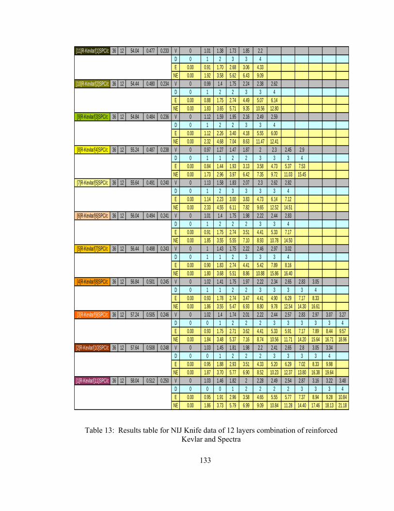
133
[11]R-Kevlar/[1]SPC/c 36 12 54.04 0.477 0.233 V 0 1.01 1.38 1.73 1.85 2.2D 0 1 2 3 3 4E 0.00 0.91 1.70 2.68 3.06 4.33
NE 0.00 1.92 3.58 5.62 6.43 9.09[10]R-Kevlar/[2]SPC/c 36 12 54.44 0.480 0.234 V 0 0.99 1.4 1.75 2.24 2.38 2.62
D 0 1 2 2 3 3 4E 0.00 0.88 1.75 2.74 4.49 5.07 6.14
NE 0.00 1.83 3.65 5.71 9.35 10.56 12.80[9]R-Kevlar/[3]SPC/c 36 12 54.84 0.484 0.236 V 0 1.12 1.59 1.95 2.16 2.49 2.59
D 0 1 2 2 3 3 4E 0.00 1.12 2.26 3.40 4.18 5.55 6.00
NE 0.00 2.32 4.68 7.04 8.63 11.47 12.41[8]R-Kevlar/[4]SPC/c 36 12 55.24 0.487 0.238 V 0 0.97 1.27 1.47 1.87 2 2.3 2.45 2.9
D 0 1 1 2 2 3 3 3 4E 0.00 0.84 1.44 1.93 3.13 3.58 4.73 5.37 7.53
NE 0.00 1.73 2.96 3.97 6.42 7.35 9.72 11.03 15.45[7]R-Kevlar/[5]SPC/c 36 12 55.64 0.491 0.240 V 0 1.13 1.58 1.83 2.07 2.3 2.62 2.82
D 0 1 2 3 3 3 3 4E 0.00 1.14 2.23 3.00 3.83 4.73 6.14 7.12
NE 0.00 2.33 4.55 6.11 7.82 9.65 12.52 14.51[6]R-Kevlar/[6]SPC/c 36 12 56.04 0.494 0.241 V 0 1.01 1.4 1.75 1.98 2.22 2.44 2.83
D 0 1 2 2 2 3 3 4E 0.00 0.91 1.75 2.74 3.51 4.41 5.33 7.17
NE 0.00 1.85 3.55 5.55 7.10 8.93 10.78 14.50[5]R-Kevlar/[7]SPC/c 36 12 56.44 0.498 0.243 V 0 1 1.43 1.75 2.22 2.46 2.97 3.02
D 0 1 1 2 3 3 3 4E 0.00 0.90 1.83 2.74 4.41 5.42 7.89 8.16
NE 0.00 1.80 3.68 5.51 8.86 10.88 15.86 16.40[4]R-Kevlar/[8]SPC/c 36 12 56.84 0.501 0.245 V 0 1.02 1.41 1.75 1.97 2.22 2.34 2.65 2.83 3.05
D 0 1 1 2 2 3 3 3 3 4E 0.00 0.93 1.78 2.74 3.47 4.41 4.90 6.29 7.17 8.33
NE 0.00 1.86 3.55 5.47 6.93 8.80 9.78 12.54 14.30 16.61[3]R-Kevlar/[9]SPC/c 36 12 57.24 0.505 0.246 V 0 1.02 1.4 1.74 2.01 2.22 2.44 2.57 2.83 2.97 3.07 3.27
D 0 0 1 2 2 2 3 3 3 3 3 4E 0.00 0.93 1.75 2.71 3.62 4.41 5.33 5.91 7.17 7.89 8.44 9.57
NE 0.00 1.84 3.48 5.37 7.16 8.74 10.56 11.71 14.20 15.64 16.71 18.96[2]R-Kevlar/[10]SPC/c 36 12 57.64 0.508 0.248 V 0 1.03 1.45 1.81 1.98 2.2 2.41 2.65 2.8 3.05 3.34
D 0 0 1 2 2 2 3 3 3 3 4E 0.00 0.95 1.88 2.93 3.51 4.33 5.20 6.29 7.02 8.33 9.98
NE 0.00 1.87 3.70 5.77 6.90 8.52 10.23 12.37 13.80 16.38 19.64[1]R-Kevlar/[11]SPC/c 36 12 58.04 0.512 0.250 V 0 1.03 1.46 1.82 2 2.28 2.49 2.54 2.87 3.16 3.22 3.48
D 0 0 0 1 2 2 2 2 3 3 3 4E 0.00 0.95 1.91 2.96 3.58 4.65 5.55 5.77 7.37 8.94 9.28 10.84
NE 0.00 1.86 3.73 5.79 6.99 9.09 10.84 11.28 14.40 17.46 18.13 21.18
Table 13: Results table for NIJ Knife data of 12 layers combination of reinforced
Kevlar and Spectra

134
[1]R-Kevlar/[11]SPC/NEAT 36 12 61.613 0.543 0.265 V 0 1 1.48 1.64 1.98 2.22 2.41 2.57 2.87D 0 1 2 2 3 3 3 3 4E 0.00 0.90 1.96 2.41 3.51 4.41 5.20 5.91 7.37
NE 0.00 1.65 3.61 4.43 6.46 8.12 9.57 10.88 13.57[2]R-Kevlar/[10]SPC/NEAT 36 12 61.186 0.540 0.263 V 0 1.01 1.4 1.74 2 2.32 2.57
D 0 1 2 2 3 3 4E 0.00 0.91 1.75 2.71 3.58 4.82 5.91
NE 0.00 1.69 3.25 5.02 6.63 8.93 10.96[3]R-Kevlar/[9]SPC/NEAT 36 12 60.759 0.536 0.262 V 0 1.02 1.41 1.74 2 2.16 2.44
D 0 2 2 3 3 3 4E 0.00 0.93 1.78 2.71 3.58 4.18 5.33
NE 0.00 1.74 3.32 5.06 6.68 7.79 9.94[4]R-Kevlar/[8]SPC/NEAT 36 12 60.332 0.532 0.260 V 0 1.01 1.43 1.77 1.98 2.22 2.37 2.59
D 0 2 2 3 3 3 3 4E 0.00 0.91 1.83 2.80 3.51 4.41 5.03 6.00
NE 0.00 1.72 3.44 5.27 6.59 8.29 9.45 11.28[5]R-Kevlar/[7]SPC/NEAT 36 12 59.905 0.528 0.258 V 0 1.02 1.45 1.77 1.98 2.24 2.4
D 0 2 2 3 3 3 4E 0.00 0.93 1.88 2.80 3.51 4.49 5.16
NE 0.00 1.76 3.56 5.31 6.64 8.50 9.76[6]R-Kevlar/[6]SPC/NEAT 36 12 59.478 0.525 0.256 V 0 1.03 1.45 1.78 2 2.22 2.41
D 0 2 2 3 3 3 4E 0.00 0.95 1.88 2.84 3.58 4.41 5.20
NE 0.00 1.81 3.59 5.41 6.83 8.41 9.91[7]R-Kevlar/[5]SPC/NEAT 36 12 59.051 0.521 0.254 V 0 1.04 1.44 1.74 2.07 2.26
D 0 2 3 3 3 4E 0.00 0.97 1.86 2.71 3.83 4.57
NE 0.00 1.86 3.56 5.20 7.36 8.78[8]R-Kevlar/[4]SPC/NEAT 36 12 58.624 0.517 0.252 V 0 1.03 1.42 1.73 2 2.12
D 0 2 3 3 3 4E 0.00 0.95 1.80 2.68 3.58 4.02
NE 0.00 1.84 3.49 5.18 6.92 7.78[9]R-Kevlar/[3]SPC/NEAT 36 12 58.197 0.513 0.251 V 0 1.01 1.43 1.77 2
D 0 2 3 3 4E 0.00 0.91 1.83 2.80 3.58
NE 0.00 1.78 3.57 5.46 6.98[10]R-Kevlar/[2]SPC/NEAT 36 12 57.77 0.509 0.249 V 0 1.01 1.47 1.75 1.97
D 0 2 3 3 4E 0.00 0.91 1.93 2.74 3.47
NE 0.00 1.79 3.80 5.38 6.82[11]R-Kevlar/[1]SPC/NEAT 36 12 57.343 0.506 0.247 V 0 1.02 1.41 1.72 1.97
D 0 2 3 3 4E 0.00 0.93 1.78 2.65 3.47
NE 0.00 1.84 3.52 5.24 6.87
Table 14: Results table for NIJ Spike data of 12 layers combination of neat Kevlar and
Spectra
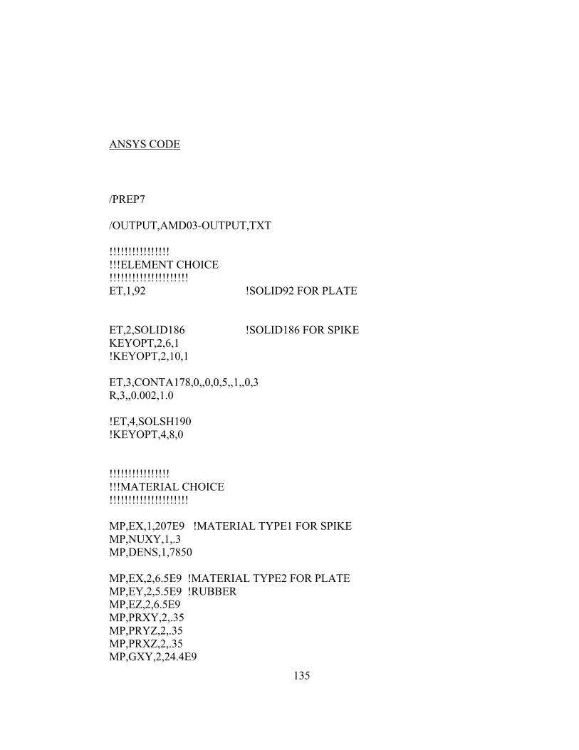
135
ANSYS CODE
/PREP7 /OUTPUT,AMD03-OUTPUT,TXT !!!!!!!!!!!!!!!! !!!ELEMENT CHOICE !!!!!!!!!!!!!!!!!!!!! ET,1,92 !SOLID92 FOR PLATE ET,2,SOLID186 !SOLID186 FOR SPIKE KEYOPT,2,6,1 !KEYOPT,2,10,1 ET,3,CONTA178,0,,0,0,5,,1,,0,3 R,3,,0.002,1.0 !ET,4,SOLSH190 !KEYOPT,4,8,0 !!!!!!!!!!!!!!!! !!!MATERIAL CHOICE !!!!!!!!!!!!!!!!!!!!! MP,EX,1,207E9 !MATERIAL TYPE1 FOR SPIKE MP,NUXY,1,.3 MP,DENS,1,7850 MP,EX,2,6.5E9 !MATERIAL TYPE2 FOR PLATE MP,EY,2,5.5E9 !RUBBER MP,EZ,2,6.5E9 MP,PRXY,2,.35 MP,PRYZ,2,.35 MP,PRXZ,2,.35 MP,GXY,2,24.4E9
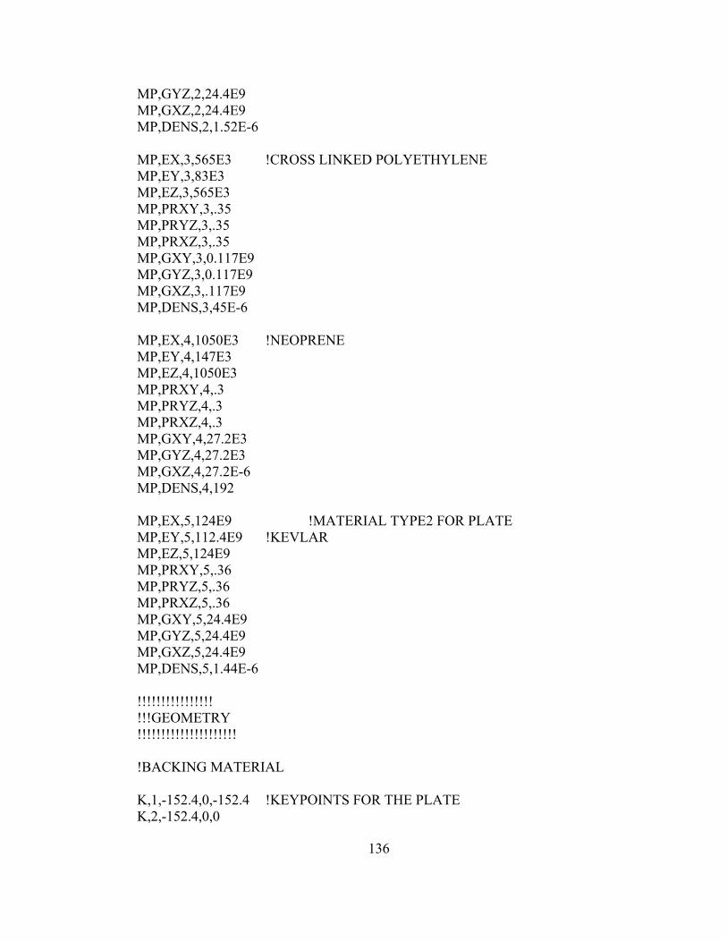
136
MP,GYZ,2,24.4E9 MP,GXZ,2,24.4E9 MP,DENS,2,1.52E-6 MP,EX,3,565E3 !CROSS LINKED POLYETHYLENE MP,EY,3,83E3 MP,EZ,3,565E3 MP,PRXY,3,.35 MP,PRYZ,3,.35 MP,PRXZ,3,.35 MP,GXY,3,0.117E9 MP,GYZ,3,0.117E9 MP,GXZ,3,.117E9 MP,DENS,3,45E-6 MP,EX,4,1050E3 !NEOPRENE MP,EY,4,147E3 MP,EZ,4,1050E3 MP,PRXY,4,.3 MP,PRYZ,4,.3 MP,PRXZ,4,.3 MP,GXY,4,27.2E3 MP,GYZ,4,27.2E3 MP,GXZ,4,27.2E-6 MP,DENS,4,192 MP,EX,5,124E9 !MATERIAL TYPE2 FOR PLATE MP,EY,5,112.4E9 !KEVLAR MP,EZ,5,124E9 MP,PRXY,5,.36 MP,PRYZ,5,.36 MP,PRXZ,5,.36 MP,GXY,5,24.4E9 MP,GYZ,5,24.4E9 MP,GXZ,5,24.4E9 MP,DENS,5,1.44E-6 !!!!!!!!!!!!!!!! !!!GEOMETRY !!!!!!!!!!!!!!!!!!!!! !BACKING MATERIAL K,1,-152.4,0,-152.4 !KEYPOINTS FOR THE PLATE K,2,-152.4,0,0

137
K,3,0,0,0 K,4,0,0,-152.4 A,1,2,3,4 !CREATE VOLUME LAYER 1 ASEL,S,AREA,,1 VOFFST,1,6.3 MAT,2 ALLSEL,ALL ASEL,S,AREA,,2 !VOLUME 2 VOFFST,2,6.3 MAT,2 ALLSEL,ALL ASEL,S,AREA,,7 !VOLUME 3 VOFFST,7,33 MAT,3 ALLSEL,ALL ASEL,S,AREA,,12 !VOLUME 4 VOFFST,12,5 MAT,4 ALLSEL,ALL ASEL,S,AREA,,17 !VOLUME 5 VOFFST,17,5 MAT,4 ALLSEL,ALL ASEL,S,AREA,,22 !VOUME 6 VOFFST,22,5 MAT,4 ALLSEL,ALL ASEL,S,AREA,,27 !VOUME 7 VOFFST,27,5 MAT,4 ALLSEL,ALL ASEL,S,AREA,,32 !VOUME 8 kevlar VOFFST,32,5 MAT,5 ALLSEL,ALL
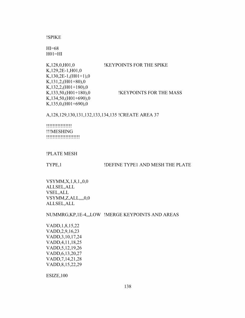
138
!SPIKE HI=68 H01=HI K,128,0,H01,0 !KEYPOINTS FOR THE SPIKE K,129,2E-1,H01,0 K,130,2E-1,(H01+1),0 K,131,2,(H01+80),0 K,132,2,(H01+180),0 K,133,50,(H01+180),0 !KEYPOINTS FOR THE MASS K,134,50,(H01+690),0 K,135,0,(H01+690),0 A,128,129,130,131,132,133,134,135 !CREATE AREA 37 !!!!!!!!!!!!!!!! !!!MESHING !!!!!!!!!!!!!!!!!!!!! !PLATE MESH TYPE,1 !DEFINE TYPE1 AND MESH THE PLATE VSYMM,X,1,8,1,,0,0 ALLSEL,ALL VSEL,ALL VSYMM,Z,ALL,,,,0,0 ALLSEL,ALL NUMMRG,KP,1E-4,,,LOW !MERGE KEYPOINTS AND AREAS VADD,1,8,15,22 VADD,2,9,16,23 VADD,3,10,17,24 VADD,4,11,18,25 VADD,5,12,19,26 VADD,6,13,20,27 VADD,7,14,21,28 VADD,8,15,22,29 ESIZE,100

139
VMESH,ALL ALLSEL,ALL ESEL,S,TYPE,,1 NSLE CM,PLATE,NODE ALLSEL,ALL NSEL,S,LOC,Y,0 !SELECT BOTTOM OF PLATE AND CREATE COMPONENT BOTTOM CM,BOTTOM,NODE ALLSEL,ALL NSEL,S,LOC,Y,68 CM,TOP,NODE ALLSEL,ALL !VSEL,S,VOLU,8,32,8 !VCLEAR,8,32,8 !TYPE,4 !VSEL,S,VOLU,8,32,8 !ALLSEL,ALL !ESIZE,100 !VMESH,ALL !ALLSEL,ALL !SPIKE MESH TYPE,2 !DEFINE TYPE2 + CREATE CYLINDER + MESH THE SPIKE MOPT,TETEXPND,2 ASEL,S,AREA,,42 MSHKEY,0 MSHAPE,1,3D VROTAT,42,0,0,0,0,0,128,135,,4 ALLSEL,ALL ESIZE,20

140
VMESH,ALL ESEL,S,TYPE,,2 !SELECT AND CREATE COMPONENT SPIKE NSLE MAT,1 !DEFINE MATERIAL FOR SPIKE CM,SPIKE,NODE ALLSEL,ALL ESEL,S,TYPE,,1 NSLE CM,PLATE,NODE ALLSEL,ALL NUMMRG,NODES,1E-4,,,LOW !MERGE NODES !GAP MESH TYPE,3 !CONTAC178 NSEL,S,NODE,,929 !PLATE NODE NSEL,S,NODE,,3656 !SPIKE NODE E,929,3656 !CREATE GAP ELEMENT %%%%% !DIRECTION IS IMPORTANT FIRST NODE CORRESPOND TO THE MOVING NODE ALLSEL,ALL TYPE,1 !ESEL,S,TYPE,,1 !NSLE NSEL,S,NODE,,SPIKE !DEFINE BOUNDARY CONDITIONS FOR THE SPIKE D,ALL,ACCY,-9.81E3 ALLSEL,ALL !NSEL,S,NODE,,SPIKE !DEFINE BOUNDARY CONDITIONS FOR THE SPIKE !D,ALL,VELY,-5 !0.08333 !ALLSEL,ALL

141
NSEL,S,NODE,,BOTTOM !DEFINE BOUNDARY CONDITIONS FOR THE PLATE D,ALL,ALL ALLSEL,ALL !NSEL,S,NODE,,1915 !D,ALL,UY,-25 !ALLSEL,ALL FINISH !EXIT PROCESSOR !!WORK!! c****************** c**** SOLUTION c****************** /SOLU !ENTER SOLUTION PROCESS !SOLCONTROL,ON NLGEOM,ON TIMINT,ON KBC,0 TIME,300 DELTIM,10 !SOLVE !AUTOTS,ON !TIMINT,ON OUTRES,ALL,ALL SOLVE

142
FINISH c****************** c**** POST26 c****************** /POST1 NSOL,1,929,U,Y PRNSOL,U,Y ESOL,2,495,929,S,EQV PRESOL,S, !/GRID,1 !XVAR,2 !NSOL,3,929,U,Y !DISPLACEMENT OF MIDDLE PLATE NODE Y !ESOL,4,495,929,S,EQV !EQUIVALENT STRESS !ADD,2,2,,,DISP,,,-1 !/AXLAB,X,DISPLACEMENT [M] !PLOT DISPLACEMENT ON X !/AXLAB,Y,EQV STRESS [Pa] !PLOT EQUIVALENT STRESS !PLVAR,3 !FINISH !/POST26 !NSOL,2,929,U,Y,IMPACT_POINT !ESOL,3,530,929,S,EQV,VON_MISES !PROD,4,2,,,,,,-1 !/AXLAB,X,DISPLACEMENT !/XRANGE,0,3

143
!/AXLAB,Y,STRESS !/YRANGE,0,1.2E9 !/AUTO,1 !XVAR,4 !PRVA,3 !FINISH