evaluation of foundation flexibility on seismic ... · performance of anchored and unanchored...
TRANSCRIPT
Evaluation of Foundation Flexibility on Seismic
Performance of Anchored and Unanchored
Aboveground Cylindrical Steel Tanks Blank line 11 pt
Blank line 11 pt
A. Bakhshi & M. Jahangiri Alikamar Civil Engineering Department, Sharif University of Technology, Tehran, Iran
Blank line 11 pt SUMMARY:
Fluid tanks are considered among most important and essential parts in lifeline systems. In this research, effect
of slab foundation flexibility on seismic performance of anchored and unanchored cylindrical steel tanks is
discussed. For this aim three wide, medium, and tall tanks with height to diameter ratios of 0.343, 0.85, and 1.53,
respectively, have been studied using FEM. These tanks were excited by 7 one-way records and then the average
of the results has been considered. In order to model the soil and comprise interactions, as well as using direct modelling, absorbent boundaries are introduced in appropriate distances. Numerical results reveal that in the case
of having a solid foundation, the value of axial and hoop stresses in tank’s wall and also uplifting of the tank’s
bottom is less than the case of flexible foundation; however, no significant difference for free surface sloshing
height has been recognized in both above-mentioned states.
Blank line 10 pt
Keywords: Steel tanks, Seismic performance, Foundation flexibility, FEM, Absorbent boundaries
Blank line 11 pt
Blank line 11 pt
1. INTRODUCTION
Blank line 11 pt
Seismic performance of tanks has attracted many researchers' interest. The first comprehensive study in this area was conducted in 1934 by [Jacobsen and Hoskins, 1934] on solid tanks. In 1957, [Housner,
1957] introduced a simple model which fluid mass divided into two solid and shaking parts. Hence,
he analyzed hydrodynamic pressure inserted to the tank wall into two components. The first
component was the impact pressure induced from accelerated mass of the tank while the latter was oscillatory pressure produced by surface waves. In a laboratory research conducted by [Cambra, 1983]
in1983, effect of foundation flexibility on the amount of uplift on both static and dynamic states was
studied. The result of that study revealed that the amount of tank’s uplift and the magnitude of created stresses on tank wall once the tank is placed on a solid foundation is smaller than the case the tank
sited on a flexible foundation. [Zaman and Koragappa, 1989] studied flexibility behavior of the
rectangular foundations in an elastic half space. They used principle of minimum potential energy and
models with symmetric geometry and loading in their study. In 2003, [Godoy and Sosa, 2003] studied the effect of local settlement of the foundation on cylindrical fluid tank with a thin wall as well as
buckling and produced stresses on tank’s wall. Their results showed that deformation created in the
shells of thin walls (induced by local settlings of the foundation) is completely different from those developed by wind force and earthquake - which are mainly affected by nonlinear behavior of the
shells. In 2008, [Bakhshi & Hassanikhah, 2008] studied seismic performance of fluid tanks in both
anchored and unanchored states. They reported that with soil flexibility increases and decrease of tank’s wall thickness, the axial and hoop tensional-compressive stresses inserted on the tank’s wall
increase considerably.[Jahangiri, 2011] studied seismic performance of steel tanks under foundation
flexibility by FEM. Results show that anchored tall tanks are more sensitive about foundation
flexibility than other tanks. Blank line 11 pt
In the present study, the effect of flexibility of slab foundations on seismic performance of
aboveground cylindrical tanks has been investigated using the finite element technic. In this study, after designing models for wide, medium, and tall tanks for both fully anchored and unanchored states,

the tanks are excited by 7 one-way records and the average of the results is measured. Furthermore,
vertical displacement of liquid surface (sloshing), tank’s axial and hoop stresses and tank’s base plate
uplifting are discussed.
Blank line 11 pt Blank line 11 pt
2. FINITE ELEMENT MODELING
Blank line 11 pt
2.1. Soil Modelling
Blank line 11 pt
To model the soils behavior, Drucker- Prager model in linear state was used. Blank line 11 pt
Blank line 10 pt
Figure 2.1. Linear Drucker - Prager
Blank line 11 pt
(2.1) Blank line 11 pt
In the equation (2-1), β is the linear yield surface slope in strain-stress plane and typically called
fraction angle of the materials. Also, d, p, and t are cohesion of the materials, equivalent compressive stress, and triaxial compressive stress, respectively.
Blank line 11 pt
Table 2.1. Soil Properties
(
) 𝜐 (
) 𝜌 (
)
0 38 400 0.29 825.6 2000
Blank line 11 pt
Where, 𝜌 is Bulk density of the soil , E is the soil’s modulus of elasticity and 𝜐 is Poisson’s ratio. For
modeling materials damping, Rayleigh method are applied.
Blank line 11 pt [ ] [ ] [ ] (2.2)
Blank line 11 pt
Where [C], [M], and [K] are matrices of damping, mass, and material’s stiffness. In addition, coefficients of α and β are damping coefficients appropriate to mass and stiffness, respectively. By
esteeming that damping ratio between both frequencies is constant, the following relationship can be
used to estimate damping coeficient.
Blank line 11 pt
{ }
[
] (2.3)
Blank line 11 pt
To determine dimensions of the soil mass, several models with different dimensions were created and
analyzed until the point of reaching a dimension in which increase of dimensions has no effect on
accuracy of the results. So, a rectangular cubic soil area with dimension of 150 × 150 × 40 meter was obtained. Furthermore, to prevent waves created by rebound from the soil mass boundaries, some
viscose dampers were installed in these boundaries. The constant coefficients of unit surface of these
dampers in directions normal and tangential to the surface can be estimated using the following equations.
Blank line 11 pt
{
(2.4)
Blank line 11 pt
where, 𝜌 is Bulk density of soil, Vp is P wave velocity, Vs is Shear wave velocity, Cn is Surface unit
constant in direction normal to the surface boundary, and Ct is Surface unit constant in direction
tangential to the surface boundary. Besides, to calculate Vp, the following equation of Lysmer is used.
Blank line 11 pt
(2.5)
Blank line 11 pt 2.2. Tank Modeling
Blank line 11 pt
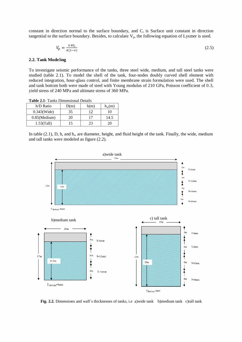
To investigate seismic performance of the tanks, three steel wide, medium, and tall steel tanks were studied (table 2.1). To model the shell of the tank, four-nodes doubly curved shell element with
reduced integration, hour-glass control, and finite membrane strain formulation were used. The shell
and tank bottom both were made of steel with Young modulus of 210 GPa, Poisson coefficient of 0.3,
yield stress of 240 MPa and ultimate stress of 360 MPa. Blank line 11 pt Table 2.1- Tanks Dimensional Details
hw(m) h(m) D(m) h/D Ratio
10 12 35 0.343(Wide)
14.5 17 20 0.85(Medium)
20 23 15 1.53(Tall)
Blank line 11 pt In table (2.1), D, h, and hw are diameter, height, and fluid height of the tank. Finally, the wide, medium
and tall tanks were modeled as figure (2.2).
Blank line 11 pt
a)wide tank
c) tall tank
b)medium tank
Blank line 11 pt Fig. 2.2. Dimensions and wall’s thicknesses of tanks, i.e a)wide tank b)medium tank c)tall tank
2.3. Fluid.Modeling
Blank line 11 pt
In hydrodynamic problems response of excited liquid storage tank systems appears the impulsive and
the convective actions. Thus, for accurate modeling of the fluid behavior it is necessary to consider sloshing phenomenon. For this regard, linear equation of state was used. Since the fluid modeled in
this study was water, fluid density was 1000 kg/m3 and the sound velocity in the fluid volume was
taken 1460 m/s. In this study, the fluid was considered as non-compressible and non-viscose. Blank line 11 pt
2.4. Foundation.Modeling
Blank line 11 pt The behavior model assumed for the foundation materials is elastic model. In term of materials, two
materials were studied for the foundation. The first material was concrete which nearly model the
behavior of the solid foundation, while the second one was soil mass which was considered for the
flexible state. Regarding to this choice, as well as discussing the effect of foundation flexibility on seismic behavior of the tanks, it is also possible to investigate the effect of lack or presence of concrete
foundation.
Blank line 11 pt In solid state, where the concrete materials were used, due to presence of reinforcement bars in the
foundation (which were not modeled in this study) to enhance the tensional strength, It is possible to
use elastic modulus [Park and Paulay, 1975]: Blank line 11 pt
√ (2.6)
Blank line 11 pt
Where, is the 28-day compressive cylinder strength of concrete (MPa) Based on these assumptions,
elastic modulus of the concrete is calculated in MPa. Since f’c was taken 36.8 MPa, the elastic
modulus of the concrete is as follows:
Blank line 11 pt
√ √ Blank li ne 11 pt
Table 2.3. Foundation Materials Properties
𝜈
Material Foundation Stiffness
0.8256 0.29 2000 Soil Flexible
28.69 0.2 2400 Concrete Solid
Blank line 11 pt
To design the slab foundation, the manual API650 (Appendix B) has been used. Finally, based on recommendations of these manual a foundation with the following dimensions is designed.
Blank line 11 pt Table 2.4. Foundation dimensions
Depth(m) Radius(m) h/D Ratio
1 18.5 0.343(wide)
1.2 11.2 0.85(medium)
1.2 8.7 1.53(tall)
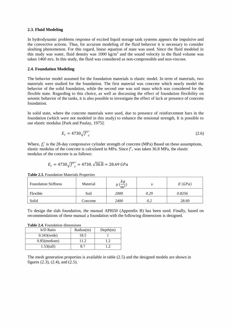
Blank line 11 pt The mesh generation properties is available in table (2.5) and the designed models are shown in
figures (2.3), (2.4), and (2.5).
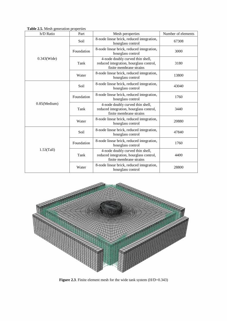
Table 2.5. Mesh generation properties
Number of elements Mesh peroperties Part h/D Ratio
67308 8-node linear brick, reduced integration,
hourglass control Soil
0.343(Wide)
3000 8-node linear brick, reduced integration,
hourglass control Foundation
3180
4-node doubly curved thin shell,
reduced integration, hourglass control,
finite membrane strains
Tank
13800 8-node linear brick, reduced integration,
hourglass control Water
43040 8-node linear brick, reduced integration,
hourglass control Soil
0.85(Medium)
1760 8-node linear brick, reduced integration,
hourglass control Foundation
3440
4-node doubly curved thin shell,
reduced integration, hourglass control,
finite membrane strains
Tank
20880 8-node linear brick, reduced integration,
hourglass control Water
47840 8-node linear brick, reduced integration,
hourglass control Soil
1.53(Tall)
1760 8-node linear brick, reduced integration,
hourglass control Foundation
4400
4-node doubly curved thin shell,
reduced integration, hourglass control,
finite membrane strains
Tank
28800 8-node linear brick, reduced integration,
hourglass control Water
Blank line 11 pt
Figure 2.3. Finite element mesh for the wide tank system (H/D=0.343)
Blank line 11 pt
Blank line 11 pt
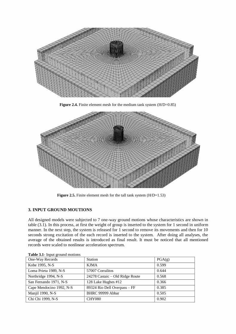
Figure 2.4. Finite element mesh for the medium tank system (H/D=0.85)
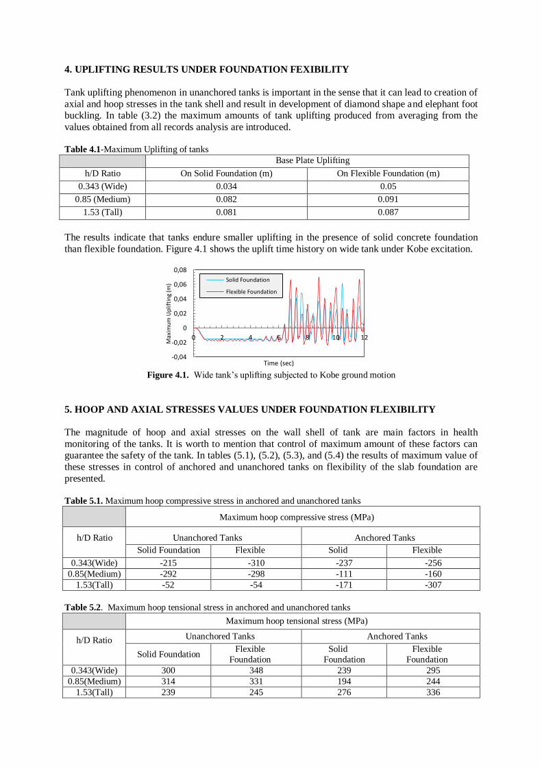
Figure 2.5. Finite element mesh for the tall tank system (H/D=1.53)
3. INPUT GROUND MOUTIONS
Blank line 11 pt
All designed models were subjected to 7 one-way ground motions whose characteristics are shown in table (3.1). In this process, at first the weight of group is inserted to the system for 1 second in uniform
manner. In the next step, the system is released for 1 second to remove its movements and then for 10
seconds strong excitation of the each record is inserted to the system. After doing all analyses, the average of the obtained results is introduced as final result. It must be noticed that all mentioned
records were scaled to nonlinear acceleration spectrum.
Blank line 11 pt Table 3.1- Input ground motions
PGA(g) Station One-Way Records
0.599 KJMA Kobe 1995, N-S
0.644 57007 Corralitos Loma Prieta 1989, N-S
0.568 24278 Castaic – Old Ridge Route Northridge 1994, N-S
0.366 128 Lake Hughes #12 San Fernando 1971, N-S
0.385 89324 Rio Dell Overpass – FF Cape Mendocino 1992, N-S
0.505 BHRC 99999 Abbar Manjil 1990, N-S
0.902 CHY080 Chi Chi 1999, N-S
4. UPLIFTING RESULTS UNDER FOUNDATION FEXIBILITY Blank line 11 pt
Tank uplifting phenomenon in unanchored tanks is important in the sense that it can lead to creation of
axial and hoop stresses in the tank shell and result in development of diamond shape and elephant foot buckling. In table (3.2) the maximum amounts of tank uplifting produced from averaging from the
values obtained from all records analysis are introduced.
Blank line 11 pt Table 4.1-Maximum Uplifting of tanks
Base Plate Uplifting
On Flexible Foundation (m) On Solid Foundation (m) h/D Ratio
0.05 0.034 0.343 (Wide)
0.091 0.082 0.85 (Medium)
0.087 0.081 1.53 (Tall)
Blank line 11 pt
The results indicate that tanks endure smaller uplifting in the presence of solid concrete foundation
than flexible foundation. Figure 4.1 shows the uplift time history on wide tank under Kobe excitation. Blank line 11 pt
Figure 4.1. Wide tank’s uplifting subjected to Kobe ground motion
5. HOOP AND AXIAL STRESSES VALUES UNDER FOUNDATION FLEXIBILITY Blank line 11 pt
The magnitude of hoop and axial stresses on the wall shell of tank are main factors in health
monitoring of the tanks. It is worth to mention that control of maximum amount of these factors can guarantee the safety of the tank. In tables (5.1), (5.2), (5.3), and (5.4) the results of maximum value of
these stresses in control of anchored and unanchored tanks on flexibility of the slab foundation are
presented. Blank line 11 pt Table 5.1. Maximum hoop compressive stress in anchored and unanchored tanks
Maximum hoop compressive stress (MPa)
Anchored Tanks Unanchored Tanks h/D Ratio
Flexible
Foundation
Solid
Foundation
Flexible
Foundation
Solid Foundation
-256 -237 -310 -215 0.343(Wide)
-160 -111 -298 -292 0.85(Medium)
-307 -171 -54 -52 1.53(Tall)
Blank line 11 pt Table 5.2. Maximum hoop tensional stress in anchored and unanchored tanks
Maximum hoop tensional stress (MPa)
Anchored Tanks Unanchored Tanks h/D Ratio Flexible
Foundation
Solid
Foundation
Flexible
Foundation Solid Foundation
295 239 348 300 0.343(Wide)
244 194 331 314 0.85(Medium)
336 276 245 239 1.53(Tall)
-0,04
-0,02
0
0,02
0,04
0,06
0,08
0 2 4 6 8 10 12
Max
imu
m U
plif
tin
g (m
)
Time (sec)
Solid Foundation
Flexible Foundation
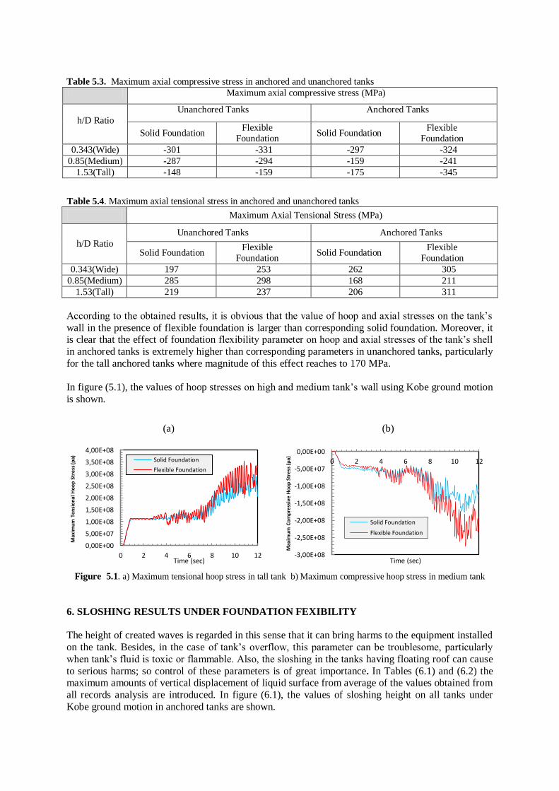
Table 5.3. Maximum axial compressive stress in anchored and unanchored tanks
Maximum axial compressive stress (MPa)
Anchored Tanks Unanchored Tanks
h/D Ratio Flexible
Foundation Solid Foundation
Flexible
Foundation Solid Foundation
-324 -297 -331 -301 0.343(Wide)
-241 -159 -294 -287 0.85(Medium)
-345 -175 -159 -148 1.53(Tall)
Blank line 11 pt
Table 5.4. Maximum axial tensional stress in anchored and unanchored tanks
Maximum Axial Tensional Stress (MPa)
Anchored Tanks Unanchored Tanks
h/D Ratio Flexible
Foundation Solid Foundation
Flexible
Foundation Solid Foundation
305 262 253 197 0.343(Wide)
211 168 298 285 0.85(Medium)
311 206 237 219 1.53(Tall)
Blank line 11 pt
According to the obtained results, it is obvious that the value of hoop and axial stresses on the tank’s
wall in the presence of flexible foundation is larger than corresponding solid foundation. Moreover, it is clear that the effect of foundation flexibility parameter on hoop and axial stresses of the tank’s shell
in anchored tanks is extremely higher than corresponding parameters in unanchored tanks, particularly
for the tall anchored tanks where magnitude of this effect reaches to 170 MPa. Blank line 11 pt
In figure (5.1), the values of hoop stresses on high and medium tank’s wall using Kobe ground motion
is shown. Blank line 11 pt
(b)
(a)
Figure 5.1. a) Maximum tensional hoop stress in tall tank b) Maximum compressive hoop stress in medium tank
Blank line 11 pt Blank line 11 pt
6. SLOSHING RESULTS UNDER FOUNDATION FEXIBILITY
Blank line 11 pt The height of created waves is regarded in this sense that it can bring harms to the equipment installed
on the tank. Besides, in the case of tank’s overflow, this parameter can be troublesome, particularly
when tank’s fluid is toxic or flammable. Also, the sloshing in the tanks having floating roof can cause
to serious harms; so control of these parameters is of great importance. In Tables (6.1) and (6.2) the maximum amounts of vertical displacement of liquid surface from average of the values obtained from
all records analysis are introduced. In figure (6.1), the values of sloshing height on all tanks under
Kobe ground motion in anchored tanks are shown.
-3,00E+08
-2,50E+08
-2,00E+08
-1,50E+08
-1,00E+08
-5,00E+07
0,00E+00
0 2 4 6 8 10 12
Max
imu
m C
om
pre
ssiv
e H
oo
p S
tre
ss (
pa)
Time (sec)
Solid Foundation
Flexible Foundation
0,00E+00
5,00E+07
1,00E+08
1,50E+08
2,00E+08
2,50E+08
3,00E+08
3,50E+08
4,00E+08
0 2 4 6 8 10 12
Max
imu
m T
en
sio
nal
Ho
op
Str
ess
(pa)
Time (sec)
Solid Foundation
Flexible Foundation
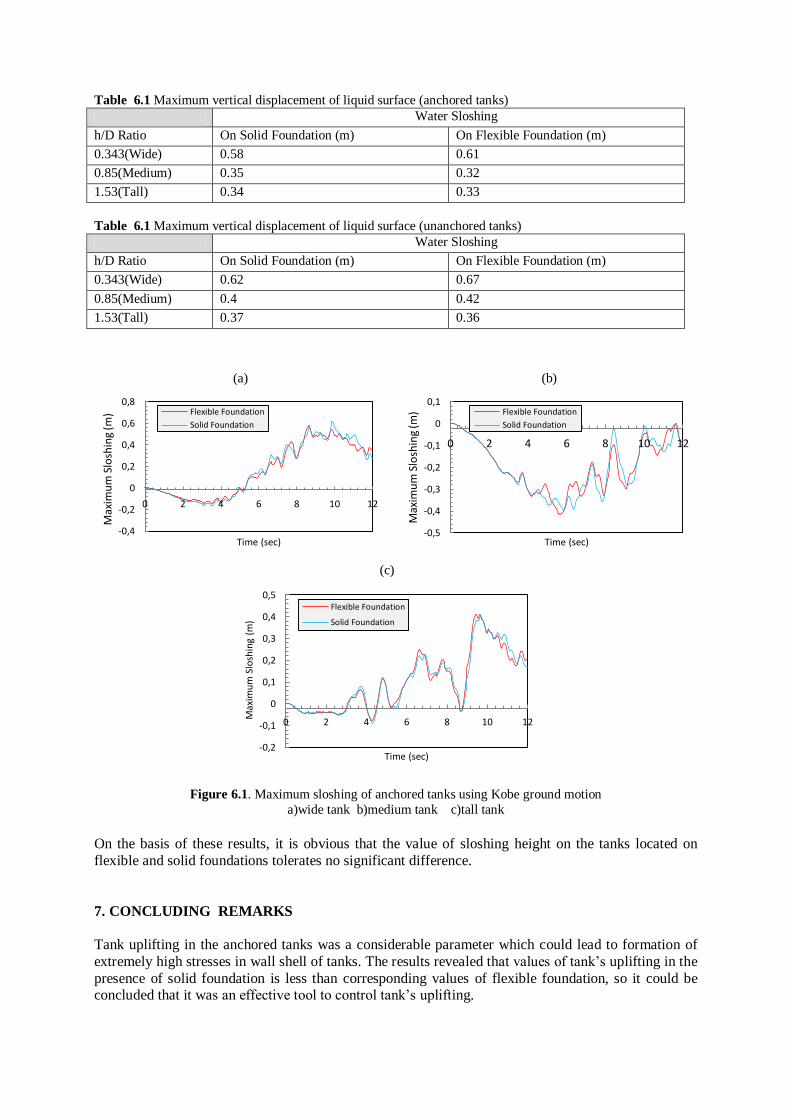
Table 6.1 Maximum vertical displacement of liquid surface (anchored tanks) Water Sloshing
On Flexible Foundation (m) On Solid Foundation (m) h/D Ratio
0.61 0.58 0.343(Wide)
0.32 0.35 0.85(Medium)
0.33 0.34 1.53(Tall)
Table 6.1 Maximum vertical displacement of liquid surface (unanchored tanks) Water Sloshing
On Flexible Foundation (m) On Solid Foundation (m) h/D Ratio
0.67 0.62 0.343(Wide)
0.42 0.4 0.85(Medium)
0.36 0.37 1.53(Tall)
(b)
(a)
(c)
Blank line 11 pt
Figure 6.1. Maximum sloshing of anchored tanks using Kobe ground motion
a)wide tank b)medium tank c)tall tank
11 pt On the basis of these results, it is obvious that the value of sloshing height on the tanks located on
flexible and solid foundations tolerates no significant difference. B
7. CONCLUDING REMARKS Blank line 10 pt
Tank uplifting in the anchored tanks was a considerable parameter which could lead to formation of
extremely high stresses in wall shell of tanks. The results revealed that values of tank’s uplifting in the
presence of solid foundation is less than corresponding values of flexible foundation, so it could be concluded that it was an effective tool to control tank’s uplifting.
Blank line 10 pt
-0,5
-0,4
-0,3
-0,2
-0,1
0
0,1
0 2 4 6 8 10 12
Max
imu
m S
losh
ing
(m)
Time (sec)
Flexible Foundation
Solid Foundation
-0,4
-0,2
0
0,2
0,4
0,6
0,8
0 2 4 6 8 10 12
Max
imu
m S
losh
ing
(m)
Time (sec)
Flexible Foundation
Solid Foundation
-0,2
-0,1
0
0,1
0,2
0,3
0,4
0,5
0 2 4 6 8 10 12 Max
imu
m S
losh
ing
(m)
Time (sec)
Flexible Foundation
Solid Foundation
Hoop and axial stresses in medium and tall unanchored tanks in the presence of solid foundation
showed no significant difference with the case of using flexible foundation; however for the wide tank,
one might notice that the stresses in the case of solid foundations show smaller values than the case of
using flexible foundation. It was also worth to mention that in anchored tanks effect of foundations flexibility on the stresses was significant: In all three anchored wide, medium, and tall tanks the value
of hoop and axial stresses in the presence of solid foundation is less than the state of using flexible
foundations – particularly in tall tanks where this difference reaches to amount of 170 MPa. It was obvious that the value of sloshing height on the tanks in the presence of flexible foundation has no
significant difference with the condition of solid foundation.Blank line 10 pt
ACKNOWLEDGEMENT
This research has been supported by Civil Engineering Department and Research and Technology Affairs
of Sharif University of Technology. Authors wish to thank gratefully this support.
REFERENCES
Blank line 10 pt
Hoskins, L.M. and Jacobsen, L.S. (1934). Water Pressure in a Tank Caused by Simulated Earthquake, Bulletin
of the seismological society of America. 24,1-32.
Housner, G.W. (1957). Dynamic pressure on accelerated fluid containers. Bulletin of the seismological society of America. 47, 5-35.
Cambra, F.J. (1983). Study of liquid storage tank seismic uplift behavior. Proceeding of the pressure vessels and
Piping Technology Conference ASME. 77, 37-46.
Zaman, M.M. and Koragappa, N. (1989). Analysis of Tank-Foundation-Half-space Interaction using an Energy
Approach. Applied Mathematical Modelling. 13:2, 66-78.
Godoy, L.A. and Sosa, E.M. (2003). Localized Support Settlements of Thin-walled Storage Tanks. Thin-Walled
Structures. 41:10, 941-955.
Bakhshi, A. and Hassanikhah, A. (2008). Comparison between Seismic Responses of Anchored and
Unanchored Cylindrical Steel Tanks. The 14th World Conference on Earthquake Engineering, Beijing, P.R.
of China.
Jahangiri, M. (2011). Study on Seismic Performance of Anchored and Unanchored Storage Tanks under
Foundation Flexibility. M.Sc. Thesis, Department of Civil Engineering, Sharif University of Technology, Tehran, Iran.
Park, R. and Paulay, T. (1975). Reinfoced Concrete Structures. John Wiley and Sons.