experimentalcharacterizationoffrp composite ... · repair system c (frp composite shield/shear...
TRANSCRIPT

Marine Structures 16 (2003) 257–274
Experimental characterization of FRPcomposite-wood pile structural response
by bending tests
Roberto Lopez-Anido*, Antonis P. Michael,Thomas C. Sandford
Department of Civil and Environmental Engineering and Advanced Engineered Wood Composites Center,
University of Maine, Orono, ME 04469, USA
Received 22 November 2002; received in revised form 20 March 2003; accepted 25 March 2003
Abstract
A special prefabricated fiber reinforced polymer (FRP) composite shield or jacket was
developed to repair wood piles in the field. Two types of load-transfer mechanisms between the
wood pile and the FRP composite shield were developed and tested: (1) cement-based
structural grout; and (2) steel shear connectors with an expanding polyurethane chemical
grout. The objective of this paper is to characterize the structural response of full-size pre-
damaged wood piles repaired with the FRP composite shield system. A three-point bending
test procedure was used to simulate the response of a pile subjected to lateral loads. The load-
deformation response, deflected shape profile, relative longitudinal displacements (slip), strain
distribution, ultimate bending moment capacity and mode of failure were evaluated. Wood
piles were pre-damaged by reducing approximately 60% of the cross-section over a portion of
the pile. It was found that a pre-damaged wood pile repaired using the FRP composite shield
with cement-based grout exceeded the bending capacity of a reference wood pile. The repair
system using the FRP composite shield with steel shear connectors and polyurethane grout did
not fully restore the bending capacity of a reference wood pile; however it can be used for
marine borer protection when wood damage is not critical.
r 2003 Elsevier Ltd. All rights reserved.
Keywords: Wood pile; Timber pile; Repair; Composite; FRP; Fiber-reinforced; Bending test; Marine
borer; Damaged pile; Structural restoration
ARTICLE IN PRESS
*Corresponding author. Tel.: +1-207-581-2119; fax: +1-207-581-2074.
E-mail address: [email protected] (R. Lopez-Anido).
0951-8339/03/$ - see front matter r 2003 Elsevier Ltd. All rights reserved.
doi:10.1016/S0951-8339(03)00021-2

1. Introduction
1.1. Background
Wood piles have been traditionally used in many marine locations for piers andone to two story waterfront buildings, especially when loose granular materials arepresent. Locally available wood piles provide a low-cost foundation system.Untreated wood piles are subjected to deterioration from marine borers, crustaceans,fungi and other sources [1]. For this reason many wood piles have been treated in thepast with preservatives, like creosote or chromated copper arsenate (CCA). Withtime, preservatives will be leached from the wood, and thus deterioration will beginin treated wood piles similar to that of untreated wood piles.When wood piles deteriorate, the conventional repair is to dismantle the pier, extract
the deteriorated piles, drive new piles and rebuild the pier over the new piles. In addition,treated extracted piles may need special disposal. For some facilities, especially whenbuildings sit on piers, extraction of all piles and driving of new piles can be difficult andcostly. In these cases repair becomes a viable alternative. Repairs are possible since theportion of the pile below the mudline is normally fully intact. The major deteriorationoccurs in the portion of the pile in the inter-tidal zone and in the splash zone (abovehigh-tide). The repair system can also reduce the rate of future deterioration byintroducing a barrier that protects the wood pile from marine borer attacks.
1.2. Structural integrity
Structural wood piles are designed to withstand driving forces, axial gravity loadsfrom the pier structure (sometimes tensile loads) and lateral loads imposed by wind
ARTICLE IN PRESS
Nomenclature
a distance from support to FRP composite shielddw wood pile design diameter at the mid-span sectionEw modulus of elasticity of the wood pileIw moment of inertia of the wood pileL total pile lengthLr pre-damaged lengthLf FRP composite shield lengthLs simply supported span lengthP lateral load applied on the wood pilep normalized (dimensionless) applied loadd normalized (dimensionless) deflection.A maximum deflection of a simply supported beam
Subscripts
w wood
R. Lopez-Anido et al. / Marine Structures 16 (2003) 257–274258

pressure, wave action, ice formation or vessel docking impact. Lateral loads imposebending moments and shear forces on the pile.When a wood pile has deteriorated, it typically loses cross-section and thus loses
capacity to sustain design loads. In this paper only the capacity for lateral loading of arepaired pile will be covered. The lateral capacity has the most unknowns in repair.Driving stresses are not a repair concern. The capacity for compressive vertical loadingis related to the cross-sectional area, and tensile vertical loading is less common.The test method for piles subjected to lateral loads requires the driving of the
wood pile into the ground followed by application of a lateral or a combinationlateral and axial load as per ASTM D3966 [2]. However, in the repair case, a pile willnot be re-driven and all the work is conducted above the ground surface, thus thestructural integrity of the repaired pile is most important.Thus it is possible to evaluate a repaired wood pile by conducting a bending test
with controlled loading and support conditions. In [3] a repair system for wood poleswas evaluated by conducting bending tests in accordance to ASTMD1036 [4]. Decaydamage was simulated by mechanically modifying the wood pole section at theground line.
1.3. Objective
The objective of this paper is to characterize the structural response in bending offull-size pre-damaged wood piles repaired with a specially developed fiber reinforcedpolymer (FRP) composite shield. The FRP composite shield was designed to fit aroundinstalled wood piles in the field. Two types of repair system were designed, installed andtested: (1) An FRP composite shield with cement-based grout between the shield andthe wood pile; and (2) An FRP composite shield with shear connectors through the pileand shield and with polyurethane grout between the wood and the shield.Installed wood piles behave as cantilever columns, where the point of fixity is
assumed to be located at a given depth below the mud line. A simply supported beamwith a concentrated load at mid span develops a bending moment and shear forcediagram equivalent to a cantilever beam with one-half the span length and one-halfthe applied tip load. Therefore, a three-point bending test procedure was adopted totest the response of a pile subjected to lateral loads. The proposed test set-up wasdesigned using ASTM D1036 [4], a standard test procedure for poles, as a guide. Theload-deformation response, deflected shape profile, relative longitudinal displace-ments (slip), strain distribution, ultimate bending moment capacity and the mode offailure were evaluated.
2. Materials and methods for pile repair
2.1. Pile prototype specimens
Commercial piles were utilized for all testing. Nine meter long, class B, southernyellow pine wood piles treated with CCA preservative were selected [5]. Intact piles
ARTICLE IN PRESSR. Lopez-Anido et al. / Marine Structures 16 (2003) 257–274 259

were tested to compare to repaired damaged piles. Damaged piles were obtained bycutting the pile to a reduced cross-section near the center of the pile. The averagemoisture content of the repaired wood piles prior to testing was approximately 10–12%.Pre-damage to three wood piles was achieved by reducing the diameter of the
cross-section over a segment of length Ld ¼ 900mm from the center span toward thepile tip. In this way, it was possible to load the pile at mid-span next to the pre-damaged segment. The reduction in radius simulated the type of Limnoria damagefound in a field inspection of the Portland, Maine harbor [1]. Approximately 62%reduction of the total cross-sectional area was applied in the laboratory to simulateLimnoria spp. necking damage. The extent of pre-damage was selected based on therequirement that any wood piles losing 50% of their cross-sectional area or more bereplaced [6].Two wood piles were used as reference and control specimens. The reference wood
pile (IW) was tested undamaged or intact. The control wood pile (DW) was pre-damaged prior to the bending test. The specimen selection served to: (1) quantify thebending stiffness and strength increase resulting from the proposed repair systems bycomparing with the reference pile, IW; and (2) establish if the capacity of a damagedwood pile, DW, can be restored with the proposed repair systems.Cylindrical FRP composite shells or sleeves with a longitudinal opening or gap
along their length were fabricated using the licensed Seemann Composites ResinInfusion Molding Process (SCRIMPTM) [7]. These especially constructed shells canbe applied over existing damaged piles in the field. Two FRP composite shells with athickness of approximately 3.3mm were used in encasing each of two pre-damagedwood piles.A unidirectional woven E-glass fabric with a weight of 880 g/m2 was selected as the
primary continuous reinforcement for the FRP composite shell. Chopped StrandMat (CSM) weighing 305 g/m2 was used as secondary non-continuous and randomlyoriented reinforcement. The FRP composite shell fiber architecture consisted ofthree layers of unidirectional continuous fabric reinforcement in the longitudinal oraxial direction (0�), one layer of unidirectional continuous fabric reinforcement inthe hoop or circumferential direction (90�), and two outer CSM layers. The fiberarchitecture design is based on maximizing fiber reinforcement in the axial directionwith a minimum amount of fibers oriented in the hoop direction. Axial fiberreinforcement contributes to both bending and axial stiffness and strength of theshell, which is required to splice the damage portion of the wood pile. Hoop fiberreinforcement provides adequate integrity to the flexible shell with the required shearstrength and mechanical fastener support. One CSM layer was placed on each faceof the shell laminate to provide improved bonding to the substrate and to develop aresin rich area for environmental protection. The resulting laminate lay-up of theFRP composite shell is [CSM/0/90/0/0/CSM]. A low viscosity epoxy-based vinylester resin, Derakane 411-C50, was selected as the matrix for the composite shells [8].The epoxy-based vinyl ester resin was selected because of its high flexibility andimpact resistance, its lower cost compared to other resin systems, such as epoxies,and its good performance in harsh marine environments.
ARTICLE IN PRESSR. Lopez-Anido et al. / Marine Structures 16 (2003) 257–274260

The two fabricated shells were bonded together with an adhesive to form the FRPcomposite shield or jacket that encased the wood pile section. An underwater curingepoxy adhesive, trade name Hydrobond 500 [9], was selected based on theperformance requirements for a wood pile repair system, [10]. Durability of thisunderwater epoxy adhesive to freeze-thaw cycles was tested [11]. The longitudinalgaps of each shell were staggered at an angle of 180� to avoid lines of weakness in theFRP composite shield. The space between the wood and the FRP composite shellswas filled with one of the grouting systems.The first repair system, B, used a cement-based underwater structural grout [12]
with a specified compressive strength at 28 days of 51.7MPa to provide contactbetween the FRP composite shield and the wood pile, as well as to complete theisolation of the damaged wood portion from marine borers. This repair system reliesprimarily on mechanical interlocking at the interface between the wood pile and thecement-based grout to transfer shear stresses.The second repair system, C, used shear connectors (steel threaded rods) through
the shield and the pile to transfer shear forces and used an expanding polyurethanenon-structural grout [13] to complete the isolation of the damaged wood portionfrom marine borers.The cement-based grout used in repair system B was placed from the bottom up to
avoid segregation of the materials and air entrapment. The thickness of the groutwas approximately 60mm. In the grouting operation for the polyurethane chemicalgrout used for repair system C, the two part grout was mixed according to thesupplier specifications and pumped from the bottom of the repaired section using apaint pot and pressurized air. As the mixture reacted with water, it expanded to fillthe space between the wood pile and the inner FRP composite shell with a finalthickness of approximately 13mm. Four steel threaded rods with a diameter of19mm were used at each end of the FRP composite shield as shear connectors inrepair system C. The steel threaded rods were spaced along the pile axisapproximately 102mm and rotated approximately 30� in the circumferentialdirection.A summary of the four pile specimens tested is summarized in Table 1. The wood
piles, graded according to ASTM D25 [5], had variable diameters and taper asshown in Table 2.
2.2. Three-point bending test method
To test the structural response of the repaired wood piles, three point bending testswere performed using ASTM D1036 [4] for wood poles as a guide. The simplysupported test method was selected to simplify the experimental setup. The woodpiles were supported at the butt and the tip, and the load was applied at the center.The span length between the two end supports was Ls ¼ 8:84m, while the total
length of the piles was L ¼ 9:14m. Each steel end support had a roller mounted on ahinge that was resting on a concrete block (See Figs. 1 and 2), which providedenough space under the pile to accommodate deflection. Since the wood piles arecircular in cross-section, wooden saddles and straps were placed on top of the end
ARTICLE IN PRESSR. Lopez-Anido et al. / Marine Structures 16 (2003) 257–274 261

supports to avoid lateral movements (See Fig. 3). Another saddle with a length of305mm was used at mid-span for load transfer from the actuator to the pile withoutslippage. The load was applied with an Instron servo-hydraulic actuator mountedunderneath the structural floor using a steel frame placed on top of the woodensaddle, which resulted in a stable loading configuration.Testing was conducted in a displacement control mode with a constant deflection
rate. The peak or maximum load was anticipated based on a beam structural model[1]. Loading was applied in cycles with increasing amplitude to assess residualdeformation. A dual ramp generator available from the Instron control software wasused to apply a constant deflection rate. Load cycles that represented 10%, 20% and40% of the expected failure load were applied to each specimen. Finally, the pilespecimen was loaded to failure, which is defined by the peak load. After the failure
ARTICLE IN PRESS
Table 1
Wood pile systems configuration
System Wood pile FRP
Composite
shield
Grout Shear
connectors
Pile
length,
L (m)
Span
length,
Ls (m)
Intact
reference
(IW)
Intact N.A. N.A. No 9.14 8.84
Damaged
control (DW)
Pre-damaged N.A. N.A. No 9.14 8.84
Repair
system B
Pre-damaged Yes Cement-
based
No 9.14 8.84
Repair
system C
Pre-damaged Yes Poly
urethane
Yes 9.14 8.84
Table 2
Wood pile systems pre-damage and bending test results
System Diameter
at butt
(mm)
Diameter
at tip
(mm)
Diameter
at load
point
(mm)
Diameter
damaged
section
(mm)
Cross-
section
reduction
(%)
Peak load
(kN)
Max.
deflection
at mid-span
(mm)
Intact
Reference
(IW)
363 305 340 N/A 0 79.0 204
Damaged
Control
(DW)
356 305 308 186 63 8.1 179
Repair
system B
362 240 284 182 62 115.5 197
Repair
system C
365 267 315 197 61 52.0 158
R. Lopez-Anido et al. / Marine Structures 16 (2003) 257–274262

load was reached, the repaired specimens, B and C, were reloaded to evaluate thebehavior of the system after it was load damaged.Vertical deflections were measured at three different locations along the length of
the pile using linear variable differential transducer (LVDT) units to obtain thedeflected shape. Deflections were measured at mid-span, and at the two ends ofthe FRP composite shield. Horizontal movement (slip) between the wood pile andthe FRP composite shield was measured on the top and bottom at the ends of theencasing shield using LVDT units. Strain gages (CEA-06-250UW-350) were bonded[14] on the top and bottom of the FRP composite shield, in the longitudinal
ARTICLE IN PRESS
Fig. 2. Schematic of test set-up for repair system C.
Fig. 1. Schematic of test set-up for repair system B.
R. Lopez-Anido et al. / Marine Structures 16 (2003) 257–274 263

direction, to monitor strains during the test (See Figs. 1 and 2). Lab View 6.0 [15] wasused to collect deflections, load and strain data.
3. Results and discussion
3.1. Intact reference pile (IW)
The reference wood pile, IW, was tested intact to provide the baseline response.The load-deflection response of the reference pile was linear to failure, as shown inFig. 4. The peak load reached by the reference pile was 79 kN. The wood pile underbending failed in tension at the mid span location where the load was applied. Afterfailure, re-loading was not possible for the reference pile.
3.2. Pre-damaged control pile (DW)
The control pile, DW, was pre-damaged with its cross-sectional area reduced by63%. This pile was tested to characterize the behavior of a damaged wood pile. Theload-deflection response of the control pile is shown in Fig. 4. The peak loadcorresponding to the control pile was 8.1 kN. The 63% reduction in cross-sectionalarea diminished the wood pile bending capacity to one-sixth of the intact referencepile (IW) value. Under bending, the damaged control pile failed in tension at thedamaged section. After failure, re-loading was not possible for the control pile.
ARTICLE IN PRESS
Fig. 3. Test set-up for repair system C.
R. Lopez-Anido et al. / Marine Structures 16 (2003) 257–274264

3.3. Repair system B (FRP composite shield/cement grout)
A pre-damaged pile with its cross-sectional area reduced by 62% over a portion ofthe pile was repaired using system B (FRP Composite Shield/Cement Grout). Theresponse of the repair system B was linear to failure (See Fig. 5). Under bending, thewood pile failed at a peak load of 115 kN (see Table 2) in tension at the end ofthe FRP composite shield, as shown in Fig. 6(a). After unloading, approximately15% of the total deflection was not recovered, which was attributed to damageaccumulation. The specimen was reloaded after failure (See second loading curvedepicted in Fig. 5). The re-loading curve was also linear with approximately the sameload-deflection slope as the peak loading curve. Failure occurred in the wood pileoutside the segment encased with the FRP composite shield. It was hypothesized thatthe FRP composite shield restored enough bending capacity to the wood pile pre-damaged section to prevent failure at this location.Two LVDT units (LH1 and LH2) that measured the horizontal differential
movement (slip) between the wood pile and the FRP composite shield were locatedclose to the end of the shield, as shown in Fig. 1. Load-slip curves are presented inFig. 7. Positive slip, which was measured on the bottom side of the pile, indicatesthat the wood surface moved out of the shield, and thus the shield was subjected totension stresses. The negative slip at the top indicates that the shield was subjected tocompressive stresses. The maximum slip value recorded was approximately 5mm forboth LVDTs. The load-slip curve indicates that there is partial interaction betweenthe wood pile and the FRP composite shield. Since top and bottom slip values aresimilar, this indicates that the FRP composite shield bent about the same neutral axisas the wood pile. Having the two components, shield and wood pile, bending about
ARTICLE IN PRESS
0
20
40
60
80
100
120
0 50 100 150 200 250 300 350 400 450 500 550
Deflection at mid-span (mm)
App
lied
load
(kN
)
Reference Pile, Intact Wood (IW)
Control Pile, Damaged Wood (DW)
Fig. 4. Load-deflection response for intact reference pile (IW) and damaged control pile (DW).
R. Lopez-Anido et al. / Marine Structures 16 (2003) 257–274 265

one single neutral axis validates the design basis that the repaired pile under lateralloads behaves as a beam system.During re-loading, a shear crack initiated at the edge of the FRP composite shield
and started propagating in the FRP composite shield towards mid-span. The crackwas located at the position where the slit of the inner shell was placed. The loadcapacity of the repaired system was drastically reduced when the crack initiated.After the crack reached mid-span, the wood pile section at the pre-damaged locationfailed. This was attributed to the observation that the pre-damaged wood pile sectionhad no load bearing contribution from the cracked FRP composite shield. Thissecondary failure of the wood pile diminished the ability of the system to furthersupport any significant lateral loads.
3.4. Repair system C (FRP composite shield/shear connectors/polyurethane grout)
A pre-damaged pile with its cross-sectional area reduced by 61% over a portion ofthe pile was repaired using system C (FRP composite shield/shear connectors/polyurethane grout). The load-deflection response of system C was linear up tofailure, as shown in Fig. 5. The peak load for the pile specimen was 52 kN. At thepeak load, the FRP composite shield failed in compression in the axial direction atmid-span (end of wood saddle), as depicted in Fig. 6(b). This damage was attributedto the observation that the compressible polyurethane grout did not provide loadbearing support between the wood pile and the FRP composite shield. Approxi-mately 16% of the total deflection was non-recoverable (inelastic).The pile specimen was re-loaded after reaching the peak load. The pile was able to
support approximately 70% load of the peak load during reloading with a lowerload-deflection slope. As more damage was introduced to the FRP composite shield,the load capacity of the system was reduced (see Fig. 5). The flexibility of the system
ARTICLE IN PRESS
0
20
40
60
80
100
120
0 5 100 150 200 250 300 350 400 450 500 550
Deflection at midspan (mm)
App
lied
load
(kN
)Repair System B
Repair System C
Fig. 5. Load-deflection response for repair systems B and C.
R. Lopez-Anido et al. / Marine Structures 16 (2003) 257–274266

using shear connectors was illustrated by the fact that the pile was loaded untilreaching the maximum stroke of the servo-hydraulic actuator (500mm) withoutcatastrophic failure.
ARTICLE IN PRESS
Fig. 6. Failure modes: (a) Tension failure in wood pile at shield end (repair system B); (b) Compression
failure in FRP composite shield (repair system C).
R. Lopez-Anido et al. / Marine Structures 16 (2003) 257–274 267

Maximum relative horizontal movement (slip) between the wood pile and the FRPcomposite shield measured with two LVDT units (LH2, and LH3) is presented inFig. 8. The maximum horizontal slip recorded was approximately 5mm for thebottom LVDT (LH2), and less than half of that value for the top LVDT (LH3). Thedifference in horizontal slip at the top and the bottom indicates that the FRPcomposite shield does not bend about the same neutral axis as the wood pile does.The observed failure mode, localized FRP composite compression failure, alsosupports the observation that the shield does not behave in beam bending with thewood pile.
3.5. Deflected profile assessment
The deflected profiles at peak load for all pile systems are depicted in Fig. 9. It wasfound that the repair system B with the cement-based grout resulted in a maximum
ARTICLE IN PRESS
0
20
40
60
80
100
120
-6 -4 -2 0 2 4 6
Horizontal slip (mm)
App
lied
Load
(kN
)
LH3 LH2
Fig. 8. Load–slip response for repair system C (load cycle to failure).
0
20
40
60
80
100
120
-6 -4 -2 0 2 4 6
Horizontal slip (mm)
App
lied
Load
(kN
)
LH1 LH2
Fig. 7. Load–slip response for repair system B (load cycle to failure).
R. Lopez-Anido et al. / Marine Structures 16 (2003) 257–274268
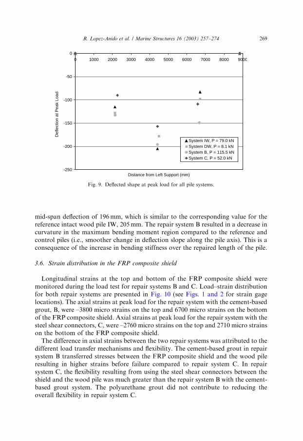
mid-span deflection of 196mm, which is similar to the corresponding value for thereference intact wood pile IW, 205mm. The repair system B resulted in a decrease incurvature in the maximum bending moment region compared to the reference andcontrol piles (i.e., smoother change in deflection slope along the pile axis). This is aconsequence of the increase in bending stiffness over the repaired length of the pile.
3.6. Strain distribution in the FRP composite shield
Longitudinal strains at the top and bottom of the FRP composite shield weremonitored during the load test for repair systems B and C. Load–strain distributionfor both repair systems are presented in Fig. 10 (see Figs. 1 and 2 for strain gagelocations). The axial strains at peak load for the repair system with the cement-basedgrout, B, were –3800 micro strains on the top and 6700 micro strains on the bottomof the FRP composite shield. Axial strains at peak load for the repair system with thesteel shear connectors, C, were –2760 micro strains on the top and 2710 micro strainson the bottom of the FRP composite shield.The difference in axial strains between the two repair systems was attributed to the
different load transfer mechanisms and flexibility. The cement-based grout in repairsystem B transferred stresses between the FRP composite shield and the wood pileresulting in higher strains before failure compared to repair system C. In repairsystem C, the flexibility resulting from using the steel shear connectors between theshield and the wood pile was much greater than the repair system B with the cement-based grout system. The polyurethane grout did not contribute to reducing theoverall flexibility in repair system C.
ARTICLE IN PRESS
-250
-200
-150
-100
-50
00 1000 2000 3000 4000 5000 6000 7000 8000 9000
Distance from Left Support (mm)
Def
lect
ion
at P
eak
Load
System IW, P = 79.0 kN System DW, P = 8.1 kNSystem B, P = 115.5 kNSystem C, P = 52.0 kN
Fig. 9. Deflected shape at peak load for all pile systems.
R. Lopez-Anido et al. / Marine Structures 16 (2003) 257–274 269

4. Load and deflection normalized parameters
To provide a meaningful comparison among the different piles evaluated (withdifferent diameters and taper) the experimental load-deflection response wasnormalized. The expression for the maximum deflection of a simply supportedbeam with constant cross-section is considered for normalizing load and deflectionvalues, as follows:
D ¼PL3
s
48EwIw
; ð1Þ
where ðEwIwÞ is the product of the modulus of elasticity by the moment of inertia ofthe wood pile at the design section. The design section is defined as the section of thewood pile at mid-span. The value of Ew was obtained from the timber poles and pilessupplement of the LRFD Manual for Engineered Wood Construction [16]. Themoment of inertia of the circular cross-section was calculated as follows:
Iw ¼pd4w64
; ð2Þ
where dw is the design diameter of the wood pile. Rearranging Eq. (1) results in
DLs
¼1
48
PL2s
EwIw
: ð3Þ
From this equation, the applied load, P; was normalized by the bending stiffness andthe span length, as follows:
p ¼PL2
s
EwIw
; ð4Þ
ARTICLE IN PRESS
0
20
40
60
80
100
120
-6000 -4000 -2000 0 2000 4000 6000 8000
Strain (micro strains)
App
lied
Load
(kN
)
System B
System C
S1S2
S4 S3
Fig. 10. Load–strain response for repair systems B and C.
R. Lopez-Anido et al. / Marine Structures 16 (2003) 257–274270
where p is the normalized (dimensionless) applied load. Similarly, the deflection atmid-span was normalized by dividing by the span length, as follows
d ¼DLs
; ð5Þ
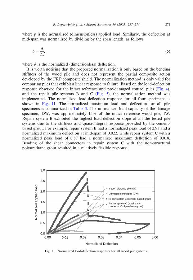
where d is the normalized (dimensionless) deflection.It is worth noticing that the proposed normalization is only based on the bending
stiffness of the wood pile and does not represent the partial composite actiondeveloped by the FRP composite shield. The normalization method is only valid forcomparing piles that exhibit a linear response to failure. Based on the load-deflectionresponse observed for the intact reference and pre-damaged control piles (Fig. 4),and the repair pile systems B and C (Fig. 5), the normalization method wasimplemented. The normalized load-deflection response for all four specimens isshown in Fig. 11. The normalized maximum load and deflection for all pilespecimens is summarized in Table 3. The normalized load capacity of the damagespecimen, DW, was approximately 15% of the intact reference wood pile, IW.Repair system B exhibited the highest load-deflection slope of all the tested pilesystems due to the stiffness and quasi-integral response provided by the cement-based grout. For example, repair system B had a normalized peak load of 2.93 and anormalized maximum deflection at mid-span of 0.022, while repair system C with anormalized peak load of 0.87 had a normalized maximum deflection of 0.018.Bending of the shear connectors in repair system C with the non-structuralpolyurethane grout resulted in a relatively flexible response.
ARTICLE IN PRESS
0.0
0.5
1.0
1.5
2.0
2.5
3.0
0.00 0.01 0.02 0.03 0.04 0.05 0.06
Normalized Deflection
Nor
mal
ized
app
lied
load Intact reference pile (IW)
Damaged control pile (DW)
Repair system B (cement-based grout)
Repair system C (steel shearconnectors/polyurethane grout)
Fig. 11. Normalized load-deflection responses for all wood pile systems.
R. Lopez-Anido et al. / Marine Structures 16 (2003) 257–274 271

5. Conclusions
Based on the results presented in this paper the following conclusions are drawn:
1. A reduction in cross-sectional area of approximately 60% on a portion of thewood pile length decreased the wood pile bending capacity to one-sixth ofthe intact value. This demonstrated the importance of repairing damaged woodpiles.
2. Use of FRP composite shells with slit openings can be applied over damaged pilesand can serve as part of a system to fully restore the bending strength of adamaged wood pile.
3. A pre-damaged wood pile with approximately 60% reduction in cross-sectionon a portion of the length was repaired using the FRP composite shield withcement-based structural grout. It exceeded the bending capacity of an intactreference wood pile. When peak load normalization is considered to accountfor the variations in wood pile diameter and taper, this repair system resultedin three times the normalized peak load capacity of the intact reference woodpile.
4. A pre-damaged wood pile with approximately 60% reduction in cross-section ona portion of the length was repaired using the FRP composite shield with shearconnectors and polyurethane grout. It only restored the bending capacity to two-thirds of an intact reference wood pile. When peak load normalization isconsidered to account for the variations in wood pile diameter and taper, thisrepair system resulted in 90% the normalized peak load capacity of the intactreference wood pile.
5. Transfer of stresses from the FRP composite shield to the wood pile is betteraccomplished using cement-based grout than with more flexible steel shearconnectors. The bending strength of the FRP composite shield/cement groutrepair system is more than double the bending strength of the FRP compositeshield with steel shear connectors repair system.
ARTICLE IN PRESS
Table 3
Normalized load and deflection
System Span length,
Ls (m)
MOE, Ew
(GPa)
Moment of
inertia, Iw
(10�4m4)
Normalized
peak load
Normalized
max.
deflection
Intact wood
(IW)
8.84 9.65 6.56 0.97 0.023
Damaged wood
(DW)
8.84 9.65 4.42 0.15 0.021
Repair system
B
8.84 9.65 3.19 2.93 0.022
Repair system
C
8.84 9.65 4.83 0.87 0.018
R. Lopez-Anido et al. / Marine Structures 16 (2003) 257–274272

6. The FRP composite shield combined with grouting provides a strong imperviouscontainment of a damage pile section. Currently existing systems of repair do nothave impervious containment or the containment shell does not have sufficientstrength. Impervious containment of the damaged pile section discourages furthermarine borer damage to the pile.
7. The laboratory findings were based on a limited number of experiments and,therefore, the applicability of the pile repair method needs to be validated throughmonitoring waterfront installations subjected to actual marine borer damage andexterior environmental conditions.
Acknowledgements
The study on the wood-pile repair method was sponsored by the NationalOceanographic and Atmospheric Administration, US Department of Commerce,through the Sea Grant College Program Awards No. NA96RG0102 andNA16RG1034. The ongoing research work on FRP composites durability issupported by the National Science Foundation through the Grant No. CMS-0093678.
References
[1] Lopez-Anido R, Michael AP, Sandford TC, Repair of wood piles with fiber reinforced composites.
Report No. AEWC-02-22. Orono, ME: Advanced Engineered Wood Composites Center, University
of Maine. 2002. pp. 180.
[2] ASTM, D 3966-90 Standard Test Method for Piles Under Lateral Loads. West Conshohocken, PA:
American Society for Testing and Materials, 1990.
[3] EDM, Full-Scale Destructive Tests of TYFOTMS FibrwrapTM System for Wood Pole Restoration.
Fort Collins, CO: Engineering Data Management, Inc, 1995. p. 1–10.
[4] ASTM, D 1036-99 Standard Test Methods of Static Tests of Wood Poles. West Conshohocken, PA:
American Society for Testing and Materials, 1999.
[5] ASTM, D 25-91 Standard Specification for Round Timber Piles. West Conshohocken, PA: American
Society for Testing and Materials, 1999.
[6] US Army, US Navy, and US Air Force, TM 5-622: Maintenance of Waterfront Facilities. Hyattsville,
MD: United States Army, 1978 [Chapter 2 - Timber Structures, p. 2.1–2.14].
[7] TPI, An overview of the SCRIMPt technology. Warren, RI: TPI Technology, Inc, 2001.
[8] Dow, DERAKANE epoxy vinyl ester resins/chemical resistance and engineering guide. Midland, MI:
Dow Chemical Company, 1999.
[9] Superior Polymer. Technical data sheet: Hydrobond 500 underwater epoxy adhesive, Calumet, MI:
Superior Polymer Products, 2000.
[10] Lopez-Anido R, Michael AP, Sandford TC. Experimental Characterization of FRP Compo-
site-Wood Pile Interface by Push-Out Tests. J Compos Constr, ASCE, 2003, submitted for
publication.
[11] Lopez-Anido R, Michael AP, Sandford TC. Freeze-Thaw Resistance of FRP Composites Adhesive
Bonds with Underwater Curing Epoxy. J Mater Civ Eng, ASCE, 2003, submitted for publication.
[12] Five Star. Five Star Structural Concrete Underwater PG (Pump Grade Underwater Repair).
Fairfield, CT: Five Star Products, Inc., 2001. p. 2.
[13] Sika. SikaFix HH Expanding, polyurethane, chemical grout. Lyndhurst, NJ: Sika Corporation,
1998.
ARTICLE IN PRESSR. Lopez-Anido et al. / Marine Structures 16 (2003) 257–274 273

[14] Measurements Group. Strain gage applications with M-Bond AE-10 adhesive system. Raleigh, NC:
Measurements Group, Inc, 1997.
[15] National Instruments.LabVIEW, Austin, TX: National Instruments Corporation, 2000.
[16] AF&PA. Supplement: Timber Poles and Piles. In: Load and Resistance Factor Design (LRFD),
Manual for Engineered Wood Construction. Washington, DC: American Forest & Paper
Association, American Wood Council, 1996. p. 30.
ARTICLE IN PRESSR. Lopez-Anido et al. / Marine Structures 16 (2003) 257–274274