home | spdc
TRANSCRIPT
Important Notice
This document is a copyrighted IEEE Standard. You may use this document inconnection with IEEE Standards development/revision activities and/or forpersonal use relating to your own work. No further reproduction or distributionof this document is permitted without the express written permission of IEEEStandards Activities, 445 Hoes Lane, P.O. Box 1331, Piscataway, NJ 08855-1331.
IEEE Std C62.92.3-1993
IEEE Guide for the Application of Neutral Grounding in Electrical Utility Systems, Part III—Generator Auxiliary Systems
Sponsor
Surge-Protective Devices Committeeof theIEEE Power Engineering Society
Approved December 2, 1993
IEEE Standards Board
Abstract: Basic factors and general considerations in selecting the class and means of neutral groundingfor electrical generating plant auxiliary power systems are given in this guide. Apparatus to be used toachieve the desired grounding are suggested, and methods to specify the grounding devices are given.Sensitivity and selectivity of equipment ground-fault protection as affected by selection of the neutralgrounding device are discussed, with examples.Keywords: electrical generating plants, electrical utility systems, generator auxiliary systems, ground-faultprotection, grounding, neutral grounding
The Institute of Electrical and Electronics Engineers, Inc.
345 East 47th Street New York, NY 10017-2394, USA
Copyright © 1994 by the Institute of Electrical and Electronics Engineers, Inc.
All rights reserved. Published 1994. Printed in the United States of America.
ISBN 1-55937-388-1
No part of this publication may be reproduced in any form, in an electronic retrieval system or otherwise, without theprior written permission of the publisher.
IEEE Standards documents are developed within the Technical Committees of the IEEE Societies and the StandardsCoordinating Committees of the IEEE Standards Board. Members of the committees serve voluntarily and withoutcompensation. They are not necessarily members of the Institute. The standards developed within IEEE represent aconsensus of the broad expertise on the subject within the Institute as well as those activities outside of IEEE that haveexpressed an interest in participating in the development of the standard.
Use of an IEEE Standard is wholly voluntary. The existence of an IEEE Standard does not imply that there are no otherways to produce, test, purchase, market, or provide other goods and services related to the scope of the IEEE Standard.Furthermore, the view point expressed at the time a standard is approved and issued is subject to change about throughdevelopments in the state of the art and comments received from users of the standard. Every IEEE Standard issubjected to review at least every five years for revision or reaffirmation. When a document is more than five years oldand has not been reaffirmed, it is reasonable to conclude that its contents, although still of some value, do not whollyreflect the present state of the art. Users are cautioned to check to determine that they have the latest edition of anyIEEE Standard.
Comments for revision of IEEE Standards are welcome from any interested party, regardless of membership affiliationwith IEEE. Suggestions for changes in documents should be in the form of a proposed change of text, together withappropriate supporting comments.
Interpretations: Occasionally questions may arise regarding the meaning of portions of standards as they related tospecific applications. When the need for interpretations is brought to the attention of IEEE, the Institute will initiateaction to prepare appropriate responses. Since IEEE Standards represent a consensus of all concerned interests, it isimportant to ensure that any interpretation has also received the concurrence of a balance of interests. For this reasonIEEE and the members of its technical committees are not able to provide an instant response to interpretation requestsexcept in those cases where the matter has previously received formal consideration.
Comments on standards and requests for interpretations should be addressed to:
Secretary, IEEE Standards Board445 Hoes LaneP.O. Box 1331Piscataway, NJ 08855-1331USA
IEEE Standards documents may involve the use of patented technology. Their approval by the Institute ofElectrical and Electronics Engineers does not mean that using such technology for the purpose of conforming tosuch standard is authorized by the patent owner. It is the obligation of the user of such technology to obtain allnecessary permissions.
iii
Introduction
(This introduction is not a part of IEEE Std C62.92.3-1993, IEEE Guide for the Application of Neutral Grounding in ElectricalUtility Systems, Part III—Generator Auxiliary Systems.)
This guide is part of a series on neutral grounding in electrical utility systems. When the series of documents areapproved and published, they will replace IEEE Std 143-1954 , IEEE Guide for Ground-Fault Neutralizers, Groundingof Synchronous Generator Systems, and Neutral Grounding of Transmission Systems.
IEEE Std 143-1954 is a revision of AIEE No. 954, Oct. 1954, which was a compilation of the following three AIEETransaction papers:
AIEE Committee Guide Report, “Application of Ground-Fault Neutralizers,” AIEE Transactions (Power Apparatusand Systems), vol. 72, pt. III, pp. 183–190, Apr. 1953.
AIEE Committee Report, “Application Guide for the Grounding of Synchronous Generator Systems,” AIEETransactions (Power Apparatus and Systems), vol. 72, pt. III, pp. 517–530, June 1953.
AIEE Committee Report, “Application Guide on Methods of Neutral Grounding of Transmission Systems,” AIEETransactions (Power Apparatus and Systems), vol. 72, pt. III, pp. 663–668, June 1953.
The contents of Parts I–V of the revision of IEEE Std 143-1954 are based on the foregoing documents but areamplified and updated with new material from the IEEE tutorial course, “Surge Protection in Power Systems”[(79H)144-6-PWR], and other sources.
Part III covers the considerations and practices relating to grounding of generating station auxiliary power systems.The related parts are: Part I, Introduction (Theory and performance characteristics of classes of neutral grounding);Part II, Grounding of Synchronous Generator Systems; Part IV, Distribution; and Part V, Transmission Systems andSubtransmission Systems.
It is impossible to give recognition to all those who have contributed to the technology and practices of grounding ofpower systems since work involving the preparation of this guide has been in progress for over 30 years. However, theassistance of members, past and present, of the Neutral Grounding Devices Subcommittee of the Surge-ProtectiveDevices Committee, and other similar groups with comparable purposes, should be acknowledged.
Disclaimer
This guide is specifically written for electrical utility systems and does not recognize the neutral groundingrequirements for dispersed storage and generation. These requirements must recognize the restrictions imposed by thespecific network to which the dispersed storage or generation is connected. Neutral grounding of dispersed storage andgeneration needs to be coordinated with the electrical utility system.
At the time this guide was approved, the Working Group for Part III of the Neutral Grounding Devices Subcommitteehad the following membership:
David W. Jackson, Chair
C. L. BallentineA. BengeD. C. Dawson
J. R. DetweilerE. KnappJ. L. Koepfinger
B. R. LeuenbergerS. Mazumdar
Recognition is also given to a former member of the working group for significant contributions: G. A. Pillmore.
iv
The following persons were on the balloting committee:
D. C. DawsonG. L. GaibroisC. D. HansellG. S. HaralampuJ. A. HetrickA. R. HilemanDavid W. Jackson
R. A. JonesJ. L. KoepfingerG. E. LeeD. W. LenkB. R. LeuenbergerA. W. MaguireY. Musa
J. C. OsterhoutK. B. StumpE. R. Taylor, Jr.R. ThallamS. G. Whisenant
At the time this standard was published, it was under consideration for approval as an American National Standard.The Accredited Standards Committee on Surge Arresters, C62, had the following members at the time this documentwas sent to letter ballot:
Joseph L. Koepfinger, Chair John A. Gauthier, Secretary
Organization Represented Name of Representative
Association of American Railroads Wayne Etter
Bonneville Power Administration G. E. Lee
Canadian Standards Association D. M. Smith
Electric Light and Power R. A JonesH. E. Foelker
W. A. MaguireF. Martinez
J. W. Wilson M. C. Mingoia (Alt.)
Exchange Carriers Standards Association Chrysanthos Chrysanthou
Institute of Electrical and Electronics Engineers J. L. KoepfingerJ. J. Burke
G. L. GaibroisW. H. Kapp
S.S. Kershaw, Jr.C. Hansell (Alt.)
Edgar Taylor (Alt.)
National Electrical Manufacturers Association Dennis W. LenkBernhard Wolff
D. Worden Larry Bock (Alt.)
Members-at-Large J. OsterhoutB. Panesar
R. B. Standler
Rural Electrification Administration George J. Bagnall
Underwriters Laboratories P. NotarianLarry Williams (Alt.)
v
When the IEEE Standards Board approved this standard on December 2, 1993, it had the following membership:
Wallace S. Read, Chair Donald C. Loughry, Vice Chair
Andrew G. Salem, Secretary
Gilles A. BarilJosé A. Berrios de la PazClyde R. CampDonald C. FleckensteinJay Forster*David F. FranklinRamiro GarciaDonald N. Heirman
Jim IsaakBen C. JohnsonWalter J. KarplusLorraine C. KevraE. G. “Al” KienerIvor N. KnightJoseph L. Koepfinger*D. N. “Jim” Logothetis
Don T Michael*Marco W. MigliaroL. John RankineArthur K. ReillyRonald H. ReimerGary S. RobinsonLeonard L. TrippDonald W. Zipse
*Member Emeritus
Also included are the following nonvoting IEEE Standards Board liaisons:
Satish K. AggarwalJames Beall
Richard B. EngelmanDavid E. Soffrin
Stanley I. Warshaw
Mary Lynne NielsenIEEE Standards Project Editor

vi
CLAUSE PAGE
1. Overview.............................................................................................................................................................1
1.1 Scope.......................................................................................................................................................... 11.2 Purpose....................................................................................................................................................... 1
2. References...........................................................................................................................................................2
3. Introduction.........................................................................................................................................................2
3.1 Principal characteristics ............................................................................................................................. 23.2 Past and present practice ............................................................................................................................ 2
4. Basic considerations............................................................................................................................................4
4.1 Basic factors ............................................................................................................................................... 44.2 Service continuity ...................................................................................................................................... 44.3 Damage criterion........................................................................................................................................ 54.4 Magnitude of overvoltages......................................................................................................................... 64.5 Sensitivity and selectivity of ground-fault relaying................................................................................... 84.6 Magnitude of ground-fault current............................................................................................................. 94.7 Emergency, standby, vital, and safety-related ac and dc systems............................................................ 10
5. Grounding classes usually applied....................................................................................................................10
5.1 Ungrounded.............................................................................................................................................. 105.2 Resistance grounding ............................................................................................................................... 115.3 Effective grounding (solid or direct)........................................................................................................ 115.4 Grounding dc control systems.................................................................................................................. 12
6. Selecting the grounding device .........................................................................................................................12
6.1 Grounding—general................................................................................................................................. 126.2 Selection of a neutral grounding resistor ................................................................................................. 12
7. Bibliography......................................................................................................................................................16
Annex A (Normative) Ground-fault protection ............................................................................................................18
Annex B (Normative) Ground-fault location................................................................................................................20
1
IEEE Guide for the Application of Neutral Grounding in Electrical Utility Systems, Part III—Generator Auxiliary Systems
1. Overview
1.1 Scope
This guide summarizes the general considerations in grounding of generating station auxiliary power systems anddiscusses the factors to be considered in selecting between the appropriate grounding classes and in specifyingequipment ratings. This guide applies to both medium-voltage and low-voltage auxiliary power systems. Groundingand bonding to achieve practical safeguarding of persons is fulfilled by electrically connecting equipment frames andenclosures and interconnecting wiring raceways to the station grounding network (see IEEE Std 142-1991 1), asrequired by ANSI C2-1993. References to safety in this guide mean freedom from equipment damage. The emphasisis on reliability and availability of auxiliary system service achieved through control of ground-fault currents andtransient overvoltages.
This guide is specifically written for electrical utility systems and does not recognize the neutral groundingrequirements for dispersed storage and generation. These requirements must recognize the restrictions imposed by thespecific network to which the dispersed storage or generation is connected. Neutral grounding of dispersed storage andgeneration needs to be coordinated with the electrical utility system.
1.2 Purpose
The purpose of this guide is to present some basic considerations for the selection of neutral grounding parameters thatwill provide for the control of ground-fault currents and overvoltage on auxiliary systems of electrical utility three-phase generators.
1Information on references can be found in clause 2.
2 Copyright © 1993 IEEE All Rights Reserved
IEEE C62.92.3-1993 IEEE GUIDE FOR THE APPLICATION OF NEUTRAL GROUNDING IN ELECTRICAL
2. References
This standard shall be used in conjunction with the following publications. When the following standards aresuperseded by an approved revision, the revision shall apply.
Accredited Standards Committee C2-1993, National Electrical Safety Code (ANSI).2
IEEE Std 32-1972 (Reaff 1991), IEEE Standard Requirements, Terminology, and Test Procedures for NeutralGrounding Devices (ANSI).3
IEEE Std 80-1986 (Reaff 1991), IEEE Guide for Safety in AC Substation Grounding (ANSI).
IEEE Std 100-1992, The New IEEE Standard Dictionary of Electrical and Electronics Terms (ANSI).
IEEE Std 142-1991, IEEE Recommended Practice for Grounding of Industrial and Commercial Power Systems (IEEEGreen Book) (ANSI).
IEEE Std C62.92.1-1987 (Reaff 1993), IEEE Guide for the Application of Neutral Grounding in Electrical UtilitySystems, Part I—Introduction (ANSI).
IEEE Std C62.92.2-1989, IEEE Guide for the Application of Neutral Grounding in Electrical Utility Systems, PartII— rounding of Synchronous Generator Systems (ANSI).
IEEE Std C62.92.4-1991, IEEE Guide for the Application of Neutral Grounding in Electrical Utility Systems, PartIV—Distribution (ANSI).
3. Introduction
3.1 Principal characteristics
The principal performance characteristics of the various classes of system neutral grounding, as well as the majorconsiderations in selecting an appropriate class, are presented in IEEE Std C62.92.1-1987. Application techniques forhigh-resistance grounding are developed in the discussion and examples of IEEE Std C62.92.2-1989. Theseconsiderations are directly applicable to grounding generating station auxiliary service systems. The user of this guideis presumed to be familiar with these two standards.
3.2 Past and present practice
Station auxiliary systems have in the past been quite commonly operated ungrounded, and some still are. It has longbeen recognized that ungrounded systems are actually grounded without intent through the system capacitance toground. Under certain fault conditions, such systems are susceptible to high transient overvoltages that can damagerotating machines and cable insulation. Consequently, neutral grounding is being increasingly used on stationauxiliary systems to control transient overvoltages [B22] .4
2The National Electrical Safety Code is available from the Institute of Electrical and Electronics Engineers, 445 Hoes Lane, P.O. Box 1331,Piscataway, NJ 08855-1331, USA.3IEEE publications are available from the Institute of Electrical and Electronics Engineers, 445 Hoes Lane, P.O. Box 1331, Piscataway, NJ 08855-1331, USA.4The numbers in brackets correspond those of the bibliography in clause 7.
Copyright © 1993 IEEE All Rights Reserved 3
UTILITY SYSTEMS, PART III—GENERATOR AUXILIARY SYSTEMS IEEE C62.92.3-1993
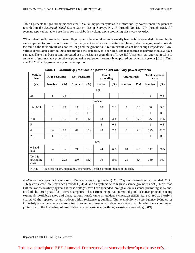
Table 1 presents the grounding practices for 389 auxiliary power systems in 199 new utility power generating plants asrecorded in the Electrical World Steam Station Design Surveys No. 13 through No. 18, 1974 through 1984. Allsystems reported in table 1 are those for which both a voltage and a grounding class were recorded.
When intentionally grounded, low-voltage systems have until recently usually been solidly grounded. Ground faultswere expected to produce sufficient current to permit selective coordination of phase protective equipment to isolatethe fault if the fault circuit was not too long and the ground-fault return circuit was of low enough impedance. Low-voltage direct-acting devices have usually had the capability to clear the faults fast enough to prevent excessive faultdamage. There has been recent increased use of resistance grounding of large 480 V systems, as reported in table 1,and even of ground-fault protective tripping using equipment commonly employed on industrial systems [B18] . Onlyone 208 V directly grounded system was reported.
Table 1—Grounding practices on power plant auxiliary power systems
Medium-voltage systems in new plants: 15 systems were ungrounded (6%), 52 systems were directly grounded (21%),126 systems were low-resistance grounded (51%), and 54 systems were high-resistance grounded (22%). More thanhalf the station auxiliary systems at these voltages have been grounded through a low resistance permitting up to one-third of the three-phase fault current amperes. This current range has permitted good selective protection usingcommonly available relays and phase current transformers in residual connection (IEEE Std 142-1991). Nearly aquarter of the reported systems adopted high-resistance grounding. The availability of core balance (window orthrough-type) zero-sequence current transformers and associated relays has made possible selectively coordinatedprotection for the low values of ground-fault current associated with high-resistance grounding [B19] .
Voltage level
High resistance Low resistanceDirect
groundingUngrounded
Total in voltage class
(kV) Number (%) Number (%) Number (%) Number (%) Number (%)
High
23 1 0.3 1 0.3
Medium
12-13-14 8 2.1 17 4.4 10 2.6 3 0.8 38 9.8
10 1 0.3 1 0.3
7–8 14 3.6 46 11.8 13 3.3 3 0.8 76 19.5
5 1 0.3 1 0.3
4 30 7.7 62 15.9 28 7.2 9 2.3 129 33.2
2.5 1 0.3 1 0.3
Low
0.6 and less
34 8.7 74 19.0 24 6.2 10 2.6 142 36.5
Total in grounding class
88 22.6 200 51.4 76 19.5 25 6.4 389 100
NOTE — Practices for 199 plants and 389 systems. Percents are percentages of the total.
4 Copyright © 1993 IEEE All Rights Reserved
IEEE C62.92.3-1993 IEEE GUIDE FOR THE APPLICATION OF NEUTRAL GROUNDING IN ELECTRICAL
4. Basic considerations
4.1 Basic factors
The basic factors to be considered in selecting a grounding class are
a) Required level of service continuity and equipment safetyb) Duration of outage and cost of lost servicec) Tolerable ground-fault damage criteria for switchgear and rotating machinesd) Extent of damage and cost to repaire) Magnitude of transient and fundamental frequency overvoltagesf) Desired level of protection against abnormal voltagesg) Magnitude of ground-fault currenth) Limiting level of ground-fault currenti) Desired selectivity, sensitivity, and speed of ground-fault relayingj) Redundancy level of process equipment; capability to maintain function with some redundant auxiliaries
forced outk) Process time requirements for orderly shutdown or transfer of functionl) Process operation tolerance to fault locating techniques
4.2 Service continuity
Whether an auxiliary power system is intentionally grounded or not, it is presumed that generating station systems areequipped with ground detectors and alarms so that grounds will not be allowed to remain on the systemunintentionally. Service continuity of ungrounded systems, or systems grounded through high resistance withoutselective relaying, may be continued for a limited period after the fault to allow an orderly procedure for locating thefault. This can contribute to high service continuity. Long search times and successive removal of several circuits fromservice for fault location can result in decreased continuity. Some nuclear plant “safety-related” systems are normallygrounded and operate ungrounded only during emergency conditions so that service continuity will not be jeopardizedby tripout on a single-phase ground fault. Two situations are critical and have influenced the choice to provideintentional grounding. If a ground fault is not located promptly and subsequently a second ground fault occurssomewhere on the system, a short circuit will exist between these two points and substantial portions of the system,usually at least two feeders, will be forced out of service without warning. The second situation arises from a hightransient overvoltage. This can cause several simultaneous insulation failures to ground on one phase in severalmachines or at separated locations. To locate these faults requires pulse current injection and tracing. Otherwise, thedifficulty of removing circuits from service in various combinations of pairs, triplets, etc., to disconnect all faultssimultaneously may be prohibitive. However, ungrounded low-voltage systems that have high-quality systeminsulation with generous margins can provide a high level of service continuity if ground faults are infrequent andmaintenance and repair are prompt and well executed. Users whose experience shows that ground faults may be keptsufficiently infrequent may prefer to operate low-voltage systems ungrounded, or with high resistance and withoutground-fault relaying, to enjoy freedom from trip-outs with no warning. Some sensitive electronic equipment(computers, microprocessors) may not be suitable for connection to ungrounded or high-resistance grounded systems.Ground-fault transient or temporary overvoltages may saturate power supplies, burn out surge suppressors, and causefires. Sensitive loads need to be selected or equipped so as to be compatible with the grounding.
Grounded and relayed systems achieve high continuity by controlling and limiting the damage caused by groundfaults, and by selective fast disconnection of faulted auxiliaries and system elements to minimize interruption of thesystem. The success of this approach depends upon adequately redundant auxiliaries, quick transfer of function toalternate auxiliaries, adequacy of preventive and restorative maintenance, and speedy repair.
Copyright © 1993 IEEE All Rights Reserved 5
UTILITY SYSTEMS, PART III—GENERATOR AUXILIARY SYSTEMS IEEE C62.92.3-1993
4.3 Damage criterion
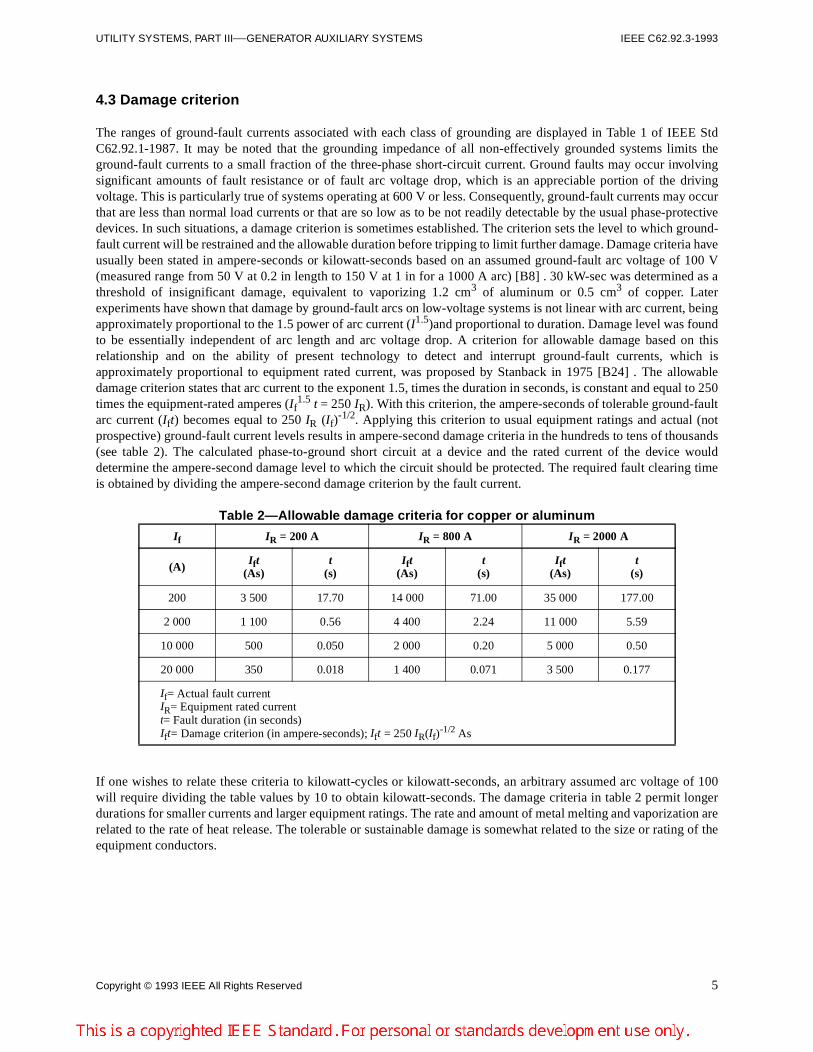
The ranges of ground-fault currents associated with each class of grounding are displayed in Table 1 of IEEE StdC62.92.1-1987. It may be noted that the grounding impedance of all non-effectively grounded systems limits theground-fault currents to a small fraction of the three-phase short-circuit current. Ground faults may occur involvingsignificant amounts of fault resistance or of fault arc voltage drop, which is an appreciable portion of the drivingvoltage. This is particularly true of systems operating at 600 V or less. Consequently, ground-fault currents may occurthat are less than normal load currents or that are so low as to be not readily detectable by the usual phase-protectivedevices. In such situations, a damage criterion is sometimes established. The criterion sets the level to which ground-fault current will be restrained and the allowable duration before tripping to limit further damage. Damage criteria haveusually been stated in ampere-seconds or kilowatt-seconds based on an assumed ground-fault arc voltage of 100 V(measured range from 50 V at 0.2 in length to 150 V at 1 in for a 1000 A arc) [B8] . 30 kW-sec was determined as athreshold of insignificant damage, equivalent to vaporizing 1.2 cm3 of aluminum or 0.5 cm3 of copper. Laterexperiments have shown that damage by ground-fault arcs on low-voltage systems is not linear with arc current, beingapproximately proportional to the 1.5 power of arc current (I1.5)and proportional to duration. Damage level was foundto be essentially independent of arc length and arc voltage drop. A criterion for allowable damage based on thisrelationship and on the ability of present technology to detect and interrupt ground-fault currents, which isapproximately proportional to equipment rated current, was proposed by Stanback in 1975 [B24] . The allowabledamage criterion states that arc current to the exponent 1.5, times the duration in seconds, is constant and equal to 250times the equipment-rated amperes (If
1.5 t = 250 IR). With this criterion, the ampere-seconds of tolerable ground-faultarc current (Ift) becomes equal to 250 IR (If)
-1/2. Applying this criterion to usual equipment ratings and actual (notprospective) ground-fault current levels results in ampere-second damage criteria in the hundreds to tens of thousands(see table 2). The calculated phase-to-ground short circuit at a device and the rated current of the device woulddetermine the ampere-second damage level to which the circuit should be protected. The required fault clearing timeis obtained by dividing the ampere-second damage criterion by the fault current.
Table 2—Allowable damage criteria for copper or aluminum
If one wishes to relate these criteria to kilowatt-cycles or kilowatt-seconds, an arbitrary assumed arc voltage of 100will require dividing the table values by 10 to obtain kilowatt-seconds. The damage criteria in table 2 permit longerdurations for smaller currents and larger equipment ratings. The rate and amount of metal melting and vaporization arerelated to the rate of heat release. The tolerable or sustainable damage is somewhat related to the size or rating of theequipment conductors.
I f IR = 200 A IR = 800 A I R = 2000 A
(A) I ft (As)
t (s)
I ft (As)
t (s)
I ft (As)
t (s)
200 3 500 17.70 14 000 71.00 35 000 177.00
2 000 1 100 0.56 4 400 2.24 11 000 5.59
10 000 500 0.050 2 000 0.20 5 000 0.50
20 000 350 0.018 1 400 0.071 3 500 0.177
If= Actual fault currentIR= Equipment rated currentt= Fault duration (in seconds)Ift= Damage criterion (in ampere-seconds); Ift = 250 IR(If)
-1/2 As
6 Copyright © 1993 IEEE All Rights Reserved
IEEE C62.92.3-1993 IEEE GUIDE FOR THE APPLICATION OF NEUTRAL GROUNDING IN ELECTRICAL
4.4 Magnitude of overvoltages
4.4.1 Fault to ground
4.4.1.1 Ungrounded system
When an ungrounded system experiences a fault to ground, transient voltage on the unfaulted phases can exceednormal line-to-ground voltage. The sustained voltages to ground on the unfaulted phases will reach line-to-line values.The voltage and current relationships between phase conductors, neutral, and ground are affected by the distributedcapacitance of circuits and equipment windings to ground. With no intentional conductive path to ground, thiscapacitance establishes a return path for ground-fault current as follows: from ground through the capacitances of theunfaulted phases to system neutral and out the faulted phase to the fault. If fault resistance is low, the predominantimpedance is capacitance; current zero occurs at the fault at voltage crest. It becomes possible for the high voltage tore-ionize the arc path and for the arc to restrike. Such an intermittent fault may be established with the arc restrikingevery half-cycle, equivalent to switching a capacitor every half-cycle. A cumulative buildup of voltage may then occurif the recovery rate of insulation strength increases after each extinction (a situation not likely to occur in an open arcbut prevalent in confined spaces within multiconductor cables, raceways, and machine windings). High transient peakvoltages may occur and will be limited either by the insulation recovery rate and strength at the fault, or by the systeminsulation strength.
4.4.1.2 Intentionally grounded system
Accidental conductor grounding on intentionally grounded systems will cause lower transient overvoltage and lowersustained overvoltage of the unfaulted phases than when the system is ungrounded. Neutral grounding is effective inreducing the possibility and magnitude of transient voltage build-up from intermittent ground faults. The groundingreduces neutral-to-ground voltage displacement and reduces the possibility of high natural frequency voltageoscillations following arc restriking. Analytical studies and system operating experience have demonstrated that themagnitude of transient overvoltage on the unfaulted phases can be limited to approximately 2.5 times the normal line-to-neutral crest value with resistance grounding (IEEE Std C62.92.1-1987). The grounding resistance is selected sothat the kilowatt loss in the neutral equals or exceeds the system three-phase capacitive kilovoltamperes to ground.
Sustained fundamental frequency overvoltages are reduced using neutral grounding by two primary effects. Thesystem grounding connection permits a ground-fault current to flow, producing internal voltage drop in the systemsources and thereby tending to reduce the system voltage. Further, the system neutral becomes grounded through boththe neutral grounding impedance and the fault impedance. These act like a series voltage divider in establishing theearth voltage at some point partway between the system neutral and the faulted phase if the two impedances havegenerally similar ratios of inductance to resistance (L/R). A sustained rise in voltage of the unfaulted phases will beless than 1.73 times the line-to-neutral voltage. If the system neutral is effectively grounded, the sustained overvoltageon unfaulted phases will not exceed 1.4 times normal line-to-neutral voltage (IEEE Std C62.92.1-1987). Thefundamental frequency overvoltage in such cases can influence selection of surge arrester ratings where these may beapplied on auxiliary systems for protection of motors against switching surges.
Voltage instrument transformer banks connected in wye and with the common or neutral point connected to ground toprovide ground detection do not constitute system grounding. However, their secondary circuits are sometimescontinuously loaded with resistors so that a few amperes of current will flow to ground in the event of a ground fault.To attempt to ground a system with voltage transformers requires a resistive loading that may be considerably abovethe accuracy voltampere rating of the transformers and may approach the thermal voltampere rating.
If voltage transformers are not heavily loaded in this manner, they may contribute to overvoltage and unbalancedconditions on an otherwise ungrounded system. The magnetizing impedance of lightly loaded transformers, in serieswith the system capacitance, may be the cause of neutral instability or neutral inversion usually associated with acondition described as “ferroresonance.” As defined in IEEE Std 100-1992, ferroresonance is a “phenomenon usuallycharacterized by overvoltages and very irregular wave shapes and associated with the excitation of one or moresaturable inductors through capacitance in series with the inductor.” Even systems that are normally grounded may be
Copyright © 1993 IEEE All Rights Reserved 7
UTILITY SYSTEMS, PART III—GENERATOR AUXILIARY SYSTEMS IEEE C62.92.3-1993
subject to this condition if the location of the neutral ground is such that it can be isolated from the voltagetransformers during a switching operation. Voltage transformers on auxiliary systems subject to switching isolationfrom neutral grounding should be loaded with resistors to control such overvoltages ([B4] , [B15] ).
4.4.2 Lightning surges
Grounding reduces the deleterious effects of lightning surges in two ways. The grounding system will frequently helpto dissipate and distribute the surge energy between the phases, thus reducing the severity of the insulation stress. In anindirect but more important manner, by holding system overvoltages down, the grounding system permits applicationof surge arresters with lower sparkover values and a higher protective margin for the equipment. The influence oflightning is minimal in the choice of grounding methods for station auxiliary systems. The surges transferred throughtransformers from overhead lines are dissipated to a very low value among the multiple circuits emanating from stationservice buses.
4.4.3 Contact with higher voltage systems
This type of exposure is rare in well-designed generating stations since circuits are universally made of insulated cable,well segregated, and protected. However, the prevalent use of a cable ladder or tray in many modern plants doesintroduce hazards, particularly if the cables are not fireproofed and different voltage systems are run on the same traywith barriered separation. The occurrence of a fault to a tray by a medium-voltage circuit can impose a substantialtransient overvoltage on the tray before fault clearing. Such a condition may break down insulation of lower voltagecircuits on the same tray, particularly in the presence of fire, and can thus subject low-voltage systems to destructiveovervoltage. Neutral grounding of the lower voltage system can mitigate these effects. The possibility of contact withhigher voltage systems, though slight in the case of station auxiliary systems, does exist and should be givenconsideration appropriate to the risks associated with the type of construction chosen.
4.4.4 Resonant voltages—inadvertent tuned ground contact
An ungrounded system can experience very high overvoltages if one of the phases faults to ground through aninductive element. Faults can readily occur in the control transformers, relays, and contactors connected at linevoltage. Since impedances are high, normal fuse protection on line-voltage control circuits is not likely to clear. Aseries voltage divider is formed, which establishes the system connection to earth voltage between two elements,composed of the inductance of the system to ground through the fault and the capacitance of the system to ground(through which the fault current re-enters the system). If these approach resonance, very high voltages appear acrossthe separate elements in quadrature with the faulted phase voltage to ground. A high voltage is thus impressed betweenthe system neutral and ground. The high voltage is an amplification of the phase voltage to ground, amplification beingdependent on the quality coefficient (Q) of the fault current circuit and the closeness of tuning. Such an occurrence cancause extremely high sustained system overvoltages at fundamental or a harmonic frequency until the fault burns free,is cleared, or multiple failures of motor windings or other system insulation force catastrophic shutdown [B4] .Damaging effects of such overvoltages can be minimized by using controls at a different voltage level. The inductanceof control transformer primary windings is considerably lower than that of relay and contactor coils and less likely toresonate with low values of capacitance. However, a suitable choice of neutral grounding techniques can eliminate thehazard entirely.
4.4.5 Switching overvoltages
Switching overvoltages caused by forcing current zero or restriking of an interrupter result from trapping energy in thecircuit. Magnetic energy exists in the fields that surround the circuit during current flow. When current is forced tozero, these fields suddenly collapse on the conductor; the energy is converted to voltage and stored as trapped chargein the system capacitance. The mechanism involves energy transfer between circuit inductance and capacitance, aspringy oscillatory system, at its resonant frequency of several thousand hertz. When disturbed in this manner, thevoltage will overshoot its static value unless purposefully damped. The high frequency and overshoot can produce ahigh rate of rise of voltage, which may increase much faster than the recovery of insulation strength in the interrupterarc path. If restrike occurs, a greater voltage overswing in the opposite polarity direction can result.
8 Copyright © 1993 IEEE All Rights Reserved
IEEE C62.92.3-1993 IEEE GUIDE FOR THE APPLICATION OF NEUTRAL GROUNDING IN ELECTRICAL
Switching overvoltages have not usually been a source of trouble on station auxiliary systems. More importantly, therecent introduction of vacuum interrupter type switchgear as a standard construction may result in switching surgeexposure of station auxiliary systems where they have not previously been subjected to such a hazard. These situationsrequire evaluation in choosing the method of system grounding. System grounding can alleviate exposure to switchingsurges by providing a drainage path for dissipating the trapped energy, thus holding the system voltage to near normalvalues.
4.5 Sensitivity and selectivity of ground-fault relaying
Sensitivity refers to the degree to which low-current faults may be detected by relaying; for example, high-impedancefaults or faults near the neutral in a motor winding. Selectivity refers to the degree to which relays and associatedinterrupters connected on series portions of systems are able to detect faults and open the circuit at the nearestupstream interrupter to cause a minimum interruption of service. The objectives of ground-fault relaying are to obtainan appropriate level of sensitivity and selectivity for a given application.
In an ungrounded system it is difficult to obtain relays that are sufficiently sensitive to detect high-impedance faultsreliably. Selective coordination of relays is usually not possible for single-line-to-ground faults. An ungroundedsystem usually operates with the system neutral floating near ground potential if the capacitances between phases andground are reasonably balanced. When a ground fault occurs on one phase, the voltage to ground on that phaseapproaches zero. The other two phases are raised in voltage with respect to ground by the amount of the faulted phasevoltage to ground minus the voltage drop of fault current flow through the fault impedance. The raised voltage of theunfaulted phases results in increased current flow through these phase capacitances to ground. The current leaves thesystem through the ground fault. A way of visualizing the situation is to imagine a single-phase voltage source, equaland opposite to the pre-fault voltage, connected at the fault location at the instant of the fault so the net fault voltage iszero. This voltage source will circulate current through the fault into the ground, through the capacitances to ground ofthe unfaulted phases back to the system neutral, through the faulted phase to the fault. The system capacitance toground is usually small. The impedance is large, and consequently the ground fault current is also small. In order toincrease current flow during ground faults sufficiently for selective relaying, it is necessary to provide a groundingsource (a lower impedance connection between system neutral and ground).
At the other extreme, a solidly grounded system provides high levels of ground-fault current that are quite adequate forrelaying purposes. The larger currents that will flow from low fault-voltage locations within the winding near theneutral of motors, generators, or transformers will allow relaying to be quite sensitive. The driving voltage at the pointof fault is not impeded by phase capacitances to ground. The fault current circulating path in a grounded system is fromthe fault to ground, through the earth (or building structure or equipment grounding conductor) to the neutral groundconnection, and back to the fault. The fault path impedance is usually quite small. The larger ground-fault currentscaused by solid grounding bring increased danger of damage to equipment. The consideration of increased damageleads to a need for ground-fault current limitation by impedance grounding.
Between these extremes lie various kinds and degrees of impedance grounding. For auxiliary power systems ingenerating stations, the most frequent choice is resistance grounding, usually classified into high or low resistance(IEEE Std C62.92.1-1987). High-resistance grounding restricts the fault current to a resistive component of faultcurrent at least equal to the capacitive fault current and usually no greater than two times the capacitive current. It thuslimits the total ground-fault current to between 1.4 and 2.2 times the capacitive fault current, and swings the phaseangle of fault current from 90° leading voltage to between 45° and 27° leading voltage. The grounding resistanceprovides damping of the ground-fault circuit natural frequency oscillations. It prevents fault arc restrikes by alteringthe current phase angle, and thus provides limitation of transient overvoltages.
Low-resistance grounding is characterized in IEEE Std C62.92.1-1987 as neutral grounding where the ratios ofsymmetrical component impedances at the fault are
a) Zero-sequence reactance to positive sequence reactance between zero and tenb) Zero-sequence resistance to zero-sequence reactance equal to or greater than two
Copyright © 1993 IEEE All Rights Reserved 9
UTILITY SYSTEMS, PART III—GENERATOR AUXILIARY SYSTEMS IEEE C62.92.3-1993
Low-resistance grounding may permit ground fault currents as high as 25% of a three-phase fault current. Formedium-voltage systems, the grounding resistor used in low-resistance grounding is usually selected to allow between200–2000 A of ground-fault current. Low-resistance grounding will limit the transient line-to-ground voltage at theonset of a fault to 2.5 times the crest of the line-to-ground operating voltage; see Note 3 to Table 1 of IEEE StdC62.92.1-1987.
The selection of low-resistance grounding is usually a compromise between capital cost of the resistor and protectiverelaying, and the risk and cost of equipment damage due to ground faults. Low-resistance grounding permitscoordinated relay protection using conventional phase and ground-fault relays with the ground-fault relays connectedin the residual connection of wye-connected current transformers, or in the corner of delta-connected currenttransformers. Zero-sequence transformers are not required. A false residual current and false tripping may be causedby saturation error during motor starting in-rush. Fault damage can be substantially greater than would result from thelow ground-fault currents of high-resistance grounding. Low-resistance grounding is frequently used to permit theapplication of reliable selective ground-fault protective relaying with some benefit in reduced fault damage toequipment by the limitation of ground-fault current.
Auxiliary power systems that may at times be supplied directly from a generator at generator voltage instead of froma transformer are likely to be grounded with high resistance. The resulting limitation of fault transient voltages and lowfault currents is consistent with the lower insulation level achievable in rotating machine windings, and thevulnerability to iron core damage if high current faults to ground were to occur in the slot portion of the winding.
When the ground fault current is very low, selective relaying is usually not feasible. Alarms actuated by current orvoltage at the grounding connection are employed to indicate ground faults somewhere on the system. Some relayselectivity is possible with ground-fault currents at the level of 100 A, though care must be taken to allow for thesaturation error of zero-sequence current transformers (window or through-type). Careful centering of cables in thewindow may be required and errors may need to be measured to set relays properly. Careful attention must be paid torunning of cable shield ground leads back through the window to avoid nullifying the system. Several steps of relayselectivity are possible for fault currents greater than 400 A, as well as a high degree of sensitivity, permitting detectionof faults in machine windings to within 10% to 5% of winding length from the neutral. As the ground-fault current isreduced below this level of several hundred amperes by increased grounding impedance, the objective of selectivitywith sensitivity becomes less attainable.
4.6 Magnitude of ground-fault current
The method of neutral grounding directly influences the magnitude of ground-fault current. Several factors aresuggested for consideration. In the case of an ungrounded system, the ground-fault current is a function of systemcapacitance to ground. For an ungrounded station auxiliary system, ground-fault currents on the order of 10 A or lesswould be expected. The use of high-resistance grounding results in fault currents up to twice those for the ungroundedcase. As the resistance is lowered, the fault current will increase. Low-resistance grounding usually permits faultcurrents in the order of 200–2000 A, while solid grounding permits considerably higher fault current on the order of15 000–20 000 A on medium-voltage systems and 50 000–100 000 A on low-voltage systems.
The extreme range of ground-fault current magnitude resulting from the different grounding methods will greatlyinfluence
Damage at the point of fault Sensitivity of ground relaying Mechanical stress on equipment Circuit breaker interrupting duty
10 Copyright © 1993 IEEE All Rights Reserved
IEEE C62.92.3-1993 IEEE GUIDE FOR THE APPLICATION OF NEUTRAL GROUNDING IN ELECTRICAL
4.7 Emergency, standby, vital, and safety-related ac and dc systems
The considerations in grounding emergency, standby, vital, or safety-related ac systems are the same as for any acsystem as described in previous subclauses. The basic factors are the same. However, on these systems, servicecontinuity is of primary importance. The purpose of emergency, standby, vital, or safety-related ac systems is to assurecontinuity of service to important and necessary loads upon loss of the normal ac supply. Thus, anything that canreasonably be done in the grounding system to assure continuous electric service is very desirable. It is also necessarythat transient overvoltages be limited to safe values.
Low-voltage ac systems are usually solidly grounded where the line-to-ground voltage on ungrounded conductors willbe 150 Vac or less. Three phase systems of 50–1000 V that serve phase-m-neutral loads should also be solidlygrounded.
240 V delta-connected systems and 480 Vac and 600 Vac wye-connected systems that do not have single phase-m-neutral loads need not be solidly grounded. For wye-connected systems 480 Vac and above (without line-to-neutralloads), there are advantages to high-resistance grounding of the system. High-resistance grounding will help controltransient overvoltages while permitting service continuity during ground fault until the fault can be cleared.
Loads on dc systems are generally those that require service continuity during ac system failures. This includes dcturbine emergency lube oil pumps and controls. Thus, for service continuity, dc systems are generally ungrounded.
5. Grounding classes usually applied
5.1 Ungrounded
Historically, a major reason for ungrounded operation of auxiliary systems has been the additional degree of servicecontinuity that it may afford in case of a fault between one phase and ground. Such a fault need not result in a serviceinterruption, but there exists the possibility of the occurrence of a second ground fault on a different phase before thefirst fault is cleared, which would result in a phase-to-phase fault. The possibility of a second ground fault may beincreased by the transient overvoltages that may result from the initial fault to ground when the neutral is not grounded(IEEE Std 142-1991).
Selective ground relaying in ungrounded systems is usually not attempted. Though relaying may be used to indicatethe existence of a system ground fault for purposes of alarm, the location of the fault may be difficult to determinebecause of the very low magnitude of fault current.
Phase voltages to ground are usually used as a means of detecting the occurrence of ground faults on a system. Grounddetection circuits may introduce ferroresonance on ungrounded systems when three voltage transformers areconnected wye primary with the neutral grounded, or when a single voltage transformer is used with its primaryconnected line-to-ground. Ferroresonance may cause high voltages to ground and excessive primary current, whichmay result in damage to voltage transformers or blowout of primary fuses. The basic method of preventingferroresonance is to prevent the voltage across the voltage transformer primary from becoming high enough to resultin saturation. There are several methods to achieve this. One is to select a voltage rating for the transformer that is highenough to avoid saturation. Frequently, resistance is added either in the corner of a delta secondary or between primaryneutral and ground to force some of the neutral displacement voltage across the loading resistor and thus limit thevoltage across the voltage transformer.
The magnitude of ground-fault current is quite low in ungrounded systems. During single line-to-ground faults,mechanical stress on equipment and damage at the point of fault are minimized. However, breaker interrupting duty isnot reduced. If not cleared promptly, a ground fault on one phase may lead to a fault on another phase at anotherlocation and with the resulting damage of a phase-phase fault. The second fault may be initiated by the heat release at

Copyright © 1993 IEEE All Rights Reserved 11
UTILITY SYSTEMS, PART III—GENERATOR AUXILIARY SYSTEMS IEEE C62.92.3-1993
the first fault, by the full phase-phase voltage imposed line-to-ground on the two unfaulted phases, or by the hightransient overvoltage that may occur at incidence of the first fault. In modem plants with shielded cables, a secondground fault, should one occur, is more likely in equipment than in the cables.
Studies ([B3] , [B5] , and [B7] ) have shown that restriking arcs in circuit breakers or faults in solid insulation may leadto high transient overvoltages in ungrounded systems. These overvoltages are suspected of causing insulation failuresin otherwise unrelated equipment during ground faults. To avoid these possibilities, it is becoming a frequent practiceto use high-resistance grounding when the operating characteristics of an ungrounded system are desired. Theelimination of high transient overvoltages will benefit connected rotating machinery and sensitive electronicequipment. However, the latter may still be at risk during a ground fault unless properly protected or isolated. See 4.2.
5.2 Resistance grounding
The ground-fault damage associated with resistance grounding is less than for a phase-phase fault on an ungroundedsystem or for a ground fault in the case of a solidly grounded neutral. The mechanical stress on equipment is reduced,usually as the square of fault current. The breaker duty for resistance-limited ground faults is much lower than phasefault duty and is not a major factor.
5.2.1 High resistance
Resistance grounding can be divided into two distinct classes: high resistance and low resistance (IEEE Std C62.92.1-1987). For high-resistance grounding, the resistor current is usually chosen to be at least equal to the capacitivecharging current of the system in order to prevent the buildup of high transient overvoltages. Frequently, the resistanceis made lower to make the resistive current somewhat larger than the capacitive current. This ensures elimination oftransient overvoltages and allows additional cable additions to the system without degrading the groundingperformance. Operation of high-resistance grounding is similar to that of an ungrounded system; i.e., ground faults areusually alarmed but not automatically isolated by tripping the circuit. However, improvements in zero-sequencecurrent transformers (through-type, window, or split-core) have made possible limited selectivity in relay applications.
5.2.2 Low resistance
Low-resistance grounding generally provides fault currents from a few hundred to a few thousand amperes. With thesevalues, it is usually possible to obtain satisfactory selectivity and sensitivity with ground relaying connected in thecurrent transformer residual circuit. When the ground-fault current is approximately equal to the largest currenttransformer primary current rating, such objectives may be readily realized. As the fault current is reduced below thisvalue, the objectives are attained with increasing difficulty. In cases where ground-fault currents are reduced to the150–500 A range, the use of zero-sequence current transformers permits satisfactory relaying sensitivity andselectivity. As ground fault currents go below the 150 A level, approaching high-resistance grounding, the relayingsensitivity and selectivity are reduced; satisfactory operation is increasingly difficult and greater portions of motorwindings near the neutral will be unprotected.
5.3 Effective grounding (solid or direct)
Effective grounding is usually obtained by a direct connection between system neutral and the earth with no intentionalimpedance. When the system neutral is effectively grounded, the transient overvoltages are held to a minimum ascompared to the other grounding methods. Ground relaying, because of the high fault-current levels, is both sensitiveand selective. The high fault current, if not cleared promptly, causes maximum fault damage and mechanical stress onequipment. It may also be sufficiently greater than three-phase currents to become a consideration in the selection ofcircuit breaker interrupting ratings.
12 Copyright © 1993 IEEE All Rights Reserved
IEEE C62.92.3-1993 IEEE GUIDE FOR THE APPLICATION OF NEUTRAL GROUNDING IN ELECTRICAL
5.4 Grounding dc control systems
Historically, dc control systems have not been grounded because of the following advantages:
Increased service continuity Prevention of spurious control circuit operation due to ground faults in control circuits
Overall, not grounding the dc systems increases the reliability of the control circuits because a single ground fault willnot cause circuit interruption and usually will not cause control circuit misoperation. Some dc control circuits withconnected capacitance to ground could misoperate upon ground fault on the dc or the supplying ac system. Thepossibility of another ground fault on the other leg of the dc system must be considered. Multiple ground faults cancause loss of control function and/or spurious control circuit operation. For this reason, ground detection circuits areused on dc systems. The ground detection system must be able to detect a ground fault on any leg of the dc system.This includes the center leg of three-wire dc systems. Ungrounded dc systems with ground fault detection circuitryhave been used by the utility industry for many years. DC systems are not subject to the overvoltage and resonanceproblems that may occur on ungrounded ac systems.
6. Selecting the grounding device
6.1 Grounding—general
The choice between use of ungrounded, solid, low-resistance or high-resistance neutral grounding in generating stationauxiliary system applications is usually based on the particular experience or preference of the individual utility. Anumber of articles have been published that record problems of destructive overvoltages and arcing faults on 480 V and600 V systems that were not intentionally grounded in some manner ([B10], [B11] , [B12] , [B14] , [B16] , [B17] ,[B20] , [B21] , [B23] , [B25] , [B26] , and [B27] ). Caution is advised when using such systems. Ground-faultmonitoring and an alarm are strongly recommended. Of the described methods of grounding auxiliary systems, onlyresistance grounding requires selection of specific grounding equipment. The ungrounded system requires only grounddetection and alarm initiating devices. The solidly grounded system requires only an adequate neutral groundingconductor. The discussion in this clause is an overview of the method for selecting the grounding resistor in each typeof low-resistance or high-resistance grounding application, along with some arguments regarding either method.
6.2 Selection of a neutral grounding resistor
The selection of a neutral grounding resistor requires determination of the ground-fault current necessary for relayingpurposes (if required) and consideration of the resistor voltage rating, ohmic value, thermal and current rating,mechanical stresses, and time rating.
The voltage rating of a resistor in the neutral-to-ground connection of a wye winding is determined by the system line-to-neutral voltage, since this is the maximum steady-state fault voltage that will be applied to the resistor. This voltageand the initial current required for relaying purposes determine the ohmic value of neutral resistance. Systemreactances are negligibly small when compared to the resistor and rarely need to be considered. The current rating willbe the same as the initial current selected for relaying purposes. The initial current will flow upon the occurrence of thefault and will diminish as heating increases the resistance, thereby lowering the current. The resistor time rating shouldbe selected on the basis of the relaying employed for fault detection. If selective relaying is employed, the duration ofthe fault will probably be less than a second, and a resistor having a 10 s rating may be employed. In cases where thecurrent is limited to low levels and an alarm is used to indicate ground faults, continued operation in the presence ofground faults would indicate that longer time ratings should be employed, such as the 10 min or extended lime rating.
Copyright © 1993 IEEE All Rights Reserved 13
UTILITY SYSTEMS, PART III—GENERATOR AUXILIARY SYSTEMS IEEE C62.92.3-1993
Two examples of equipment selection are presented for guidance in the following subclauses, low-resistancegrounding and high-resistance grounding.
6.2.1 Low-resistance grounding
Low-resistance grounding achieves the three desirable objectives of limiting transient overvoltages to acceptablevalues; limiting fault-current magnitude to minimize damage levels; and permitting sufficient fault current for fast,selective relaying. The selectivity depends upon the characteristics and coordination of the protective equipment.
A reasonable value of ground-fault current for an auxiliary system in a generating station, as provided by a low-resistance grounding resistor, is between 200–400 A. Using 400 A, the damage criterion from the equation in table 2 foran 800 A circuit breaker would be 10 000 As, or 400 A for 25 s. A typical 4160 V station service transformer with a 15000 kVA rating might be grounded with a 400 A, 1 s or 10 s neutral grounding resistor insulated for 2400 V (V1−n ). Theohmic value of the resistor (R) is determined from R = V1−n/3I0 = 2400/400 = 6 Ω. There is a relationship between relaysensitivity and magnitude of the ground-fault current. Accepted relay practice should be used that is compatible withthe level of ground-fault current permitted by the resistor. The material reduction in ground-fault current damageafforded by the grounding resistor is evidenced by considering that the maximum ground-fault current with solidneutral grounding would approach 30 000 A.
Ground-fault current selectivity at 400 A or less may require the use of zero-sequence current transformers (CTs), alsoreferred to as window-type, through-type, or ring-type CTs. The core of the CT surrounds all three phases, making thenet core flux zero for all but ground return currents. The relaying can be made more sensitive and faster than whensingle-phase CTs are used because the latter may produce spurious residual currents at times of asymmetrical motorinrush currents.
Since the core of the CT must surround all three phases, use of this type of current sensor may be limited to cablecircuits. However, very sensitive ground sensor current transformers have become available in configurations suitablefor use with busways and bus ducts.
Ground relaying sensitivity of 10% of maximum ground-fault current under minimum conditions is a typicallyacceptable value. It protects that portion of the winding that is more than 10% of the winding length away from theneutral. Improved sensitivity can be obtained by using a lower value of resistance, permitting a higher ground-faultcurrent, or if relaying considerations allow by a lower current setting. In the example above, with the 6 Ω resistor and400 A ground-fault current, a 10 A relay pickup will provide (10/400) × 100 = 2.5% sensitivity. 97.5% of the windingwould be considered protected.
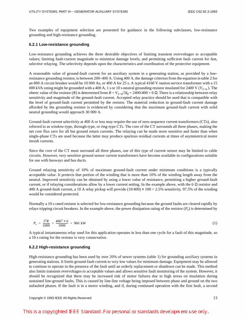
Normally a 10 s rated resistor is selected for low-resistance grounding because the ground faults are cleared rapidly byrelays tripping circuit breakers. In the example above, the power dissipation rating of the resistor (Pr) is determined by
(1)
A typical instantaneous relay used for this application operates in less than one cycle for a fault of this magnitude, soa 10 s rating for the resistor is very conservative.
6.2.2 High-resistance grounding
High-resistance grounding has been used by over 20% of newer systems (table 1) for grounding auxiliary systems ingenerating stations. It limits ground-fault current to very low values for minimum damage. Equipment may be allowedto continue to operate in the presence of the fault until an orderly replacement or shutdown can be made. This methodalso limits transient overvoltages to acceptable values and allows sensitive fault monitoring of the system. However, itshould be recognized that there may be increased risk of motor failures due to high stress on insulation duringsustained line-ground faults. This is caused by line-line voltage being imposed between phase and ground on the twounfaulted phases. If the fault is in a motor winding, and if, during continued operation with the first fault, a second
PrI 2R1000------------
4002 6×1000
-------------------- 960 kW= = =

14 Copyright © 1993 IEEE All Rights Reserved
IEEE C62.92.3-1993 IEEE GUIDE FOR THE APPLICATION OF NEUTRAL GROUNDING IN ELECTRICAL
ground fault should occur elsewhere on the system on another phase, then severe damage such as burning of stator ironlaminations can result. This type of double ground failure is a line-line fault. The damage can occur at widely separatedlocations.
6.2.2.1 Resistor in wye neutral
The ohmic value for a high-resistance grounding resistor is selected to produce ground-fault current with a resistivecomponent (Ir) at least equal to the value of capacitive current (Ic) as distributed over the entire connected subsystemfor that voltage. Thus, when Ir = Ic, then the system ratio of zero-sequence capacitive reactance (Xc0) to zero-sequenceresistance (R0) is equal to Xc0/R0 = 1. This value, which is preferred to be equal to or greater than 1.0, assures thattransient overvoltages on the connected subsystem will be within acceptable limits. To allow for increase in the amountof connected cable, the resistor should be chosen such that Ir is greater than Ic and may be as much as Ir = 2Ic.
Example
As an example of high-resistance grounding, consider a 13.8 kV system for which Xc0 = 4000 Ω/phase, so Ic0 = 13800/(1.732 × 4000) = 2.0 A/phase. It is desirable to select a neutral resistor that will provide Ir0 = 2Ic0 = 4.0 A resistivecomponent of fault current per phase. Neutral current during a ground fault is 3Ir0 = 12 A. The resistor (R) would bedetermined by R = V1−n/3Ir0 = 13 800/(1.732 × 3 × 4.0) = 664 Ω.
A resistor of 664 Ω in the primary neutral of a 13.8 kV system is expensive and is not usual practice. The resistor maybe connected to the secondary of a distribution transformer located in the neutral of a wye-connected powertransformer supplying the subsystem. This distribution transformer can be rated for system line-to-neutral voltage, asthe maximum offset of the neutral is Vl−n during ground faults. Using a 7970–120 V distribution transformer, therequired resistor is reduced in ohmic value by the inverse square of the turns ratio, or
(2)
The current rating (I) is found from
(3)
The continuous power dissipation rating (Pr) is
(4)
The kilovoltampere rating of the distribution transformer (kVA) in the neutral should be based on
(5)
If a 13 800–240 V distribution transformer were used in the neutral connection, the secondary resistor should be rated0.20 Ω and 690 A [664 × (240/13 800)2 = 0.20; and 240/1.732/0.20 = 690]. The power dissipation would remain 96 kW.
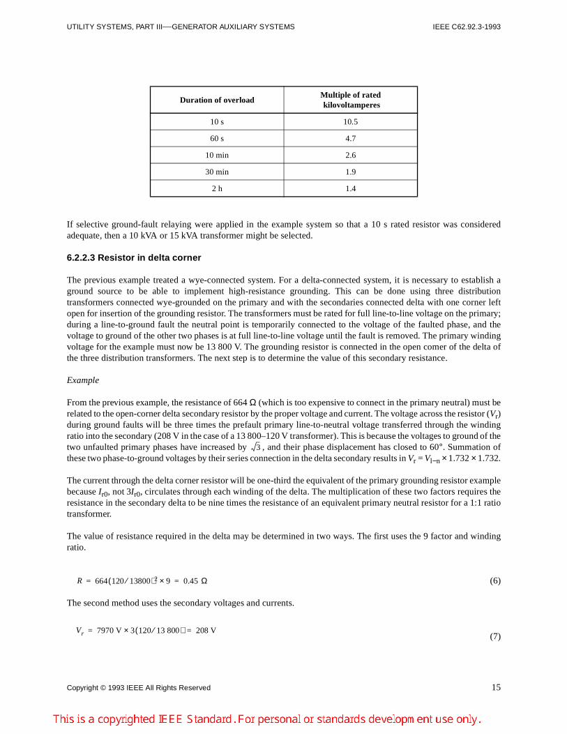
6.2.2.2 Overload capability
If faults will be cleared quickly, the short-time overload capability of distribution transformers may be considered inselecting the appropriate rating. Table 1 of IEEE Std C62.92.2-1989 lists the permissible short-time overload factorsfor distribution transformers used in neutral grounding. These factors are
R 664 120 7970⁄( )2 0.15Ω and rated 120 V,= =
I 120 V 0.15⁄( ) 797 A= =
Pr I2R 7972 0.15 1000⁄× 96 kW= = =
kVA 3 I r 0 V1 n–× 3 4× 7970×1000
------------------------------ 96 kVA= = =
Copyright © 1993 IEEE All Rights Reserved 15
UTILITY SYSTEMS, PART III—GENERATOR AUXILIARY SYSTEMS IEEE C62.92.3-1993
If selective ground-fault relaying were applied in the example system so that a 10 s rated resistor was consideredadequate, then a 10 kVA or 15 kVA transformer might be selected.
6.2.2.3 Resistor in delta corner
The previous example treated a wye-connected system. For a delta-connected system, it is necessary to establish aground source to be able to implement high-resistance grounding. This can be done using three distributiontransformers connected wye-grounded on the primary and with the secondaries connected delta with one corner leftopen for insertion of the grounding resistor. The transformers must be rated for full line-to-line voltage on the primary;during a line-to-ground fault the neutral point is temporarily connected to the voltage of the faulted phase, and thevoltage to ground of the other two phases is at full line-to-line voltage until the fault is removed. The primary windingvoltage for the example must now be 13 800 V. The grounding resistor is connected in the open comer of the delta ofthe three distribution transformers. The next step is to determine the value of this secondary resistance.
Example
From the previous example, the resistance of 664 Ω (which is too expensive to connect in the primary neutral) must berelated to the open-corner delta secondary resistor by the proper voltage and current. The voltage across the resistor (Vr)during ground faults will be three times the prefault primary line-to-neutral voltage transferred through the windingratio into the secondary (208 V in the case of a 13 800–120 V transformer). This is because the voltages to ground of thetwo unfaulted primary phases have increased by , and their phase displacement has closed to 60°. Summation ofthese two phase-to-ground voltages by their series connection in the delta secondary results in Vr = Vl−n × 1.732 × 1.732.
The current through the delta corner resistor will be one-third the equivalent of the primary grounding resistor examplebecause Ir0, not 3Ir0, circulates through each winding of the delta. The multiplication of these two factors requires theresistance in the secondary delta to be nine times the resistance of an equivalent primary neutral resistor for a 1:1 ratiotransformer.
The value of resistance required in the delta may be determined in two ways. The first uses the 9 factor and windingratio.
(6)
The second method uses the secondary voltages and currents.
(7)
Duration of overloadMultiple of rated kilovoltamperes
10 s 10.5
60 s 4.7
10 min 2.6
30 min 1.9
2 h 1.4
3
R 664 120 13800⁄( )2 9× 0.45 Ω= =
Vr 7970 V 3 120 13 800⁄( )× 208 V= =
16 Copyright © 1993 IEEE All Rights Reserved
IEEE C62.92.3-1993 IEEE GUIDE FOR THE APPLICATION OF NEUTRAL GROUNDING IN ELECTRICAL
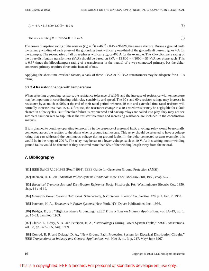
(8)
(9)
The power dissipation rating of the resistor (Pr) = I2R = 4602 × 0.45 = 96 kW, the same as before. During a ground fault,the primary winding of each phase of the grounding bank will carry one-third of the groundfault current, I0, or 4 A forthe example. The secondaries of all three phases will carry I0, or 460 A for the example. The kilovoltampere rating ofthe three distribution transformers (kVA) should be based on kVA = 13 800 × 4/1000 = 55 kVA per phase each. Thisis 0.57 times the kilovoltampere rating of a transformer in the neutral of a wye-connected primary, but the delta-connected primary requires three units instead of one.
Applying the short-time overload factors, a bank of three 5 kVA or 7.5 kVA transformers may be adequate for a 10 srating.
6.2.2.4 Resistor change with temperature
When selecting grounding resistors, the resistance tolerance of ±10% and the increase of resistance with temperaturemay be important in coordinating with relay sensitivity and speed. The 10 s and 60 s resistor ratings may increase inresistance by as much as 90% at the end of their rated period, whereas 10 min and extended time rated resistors willnormally increase less than 15 %. Of course, the resistance change in a 10 s rated resistor may be negligible for a faultcleared in a few cycles. But if breaker failure is experienced and backup relays are called into play, they may not seesufficient fault current to trip unless the resistor tolerance and increasing resistance are included in the coordinationanalysis.
If it is planned to continue operating temporarily in the presence of a ground fault, a voltage relay would be normallyconnected across the resistor to the alarm when a ground fault occurs. This relay should be selected to have a voltagerating that can withstand the continuous voltage during ground faults, In the delta-connected system example, thiswould be in the range of 200 V. The relay may be set to a lower voltage, such as 10 V. At this setting, motor windingground faults would be detected if they occurred more than 5% of the winding length away from the neutral.
7. Bibliography
[B1] IEEE Std C37.101-1985 (Reaff 1991), IEEE Guide for Generator Ground Protection (ANSI).
[B2] Beeman, D. L., ed. Industrial Power Systems Handbook. New York: McGraw-Hill, 1955, chap. 5–7.
[B3] Electrical Transmission and Distribution Reference Book. Pittsburgh, PA: Westinghouse Electric Co., 1950,chap. 14 and 19.
[B4] Industrial Power Systems Data Book. Schenectady, NY: General Electric Co., Section 220, p. 4, Feb. 2, 1953.
[B5] Peterson, H. A., Transients in Power Systems. New York, NY: Dover Publications, Inc., 1966.
[B6] Bridger, B., Jr., “High Resistance Grounding,” IEEE Transactions on Industry Applications, vol. IA–19, no. 1,pp. 15–21, Jan./Feb. 1983.
[B7] Clarke, E., Crary, S. B., and Peterson, H. A., “Overvoltages During Power System Faults,” AIEE Transactions,vol. 58, pp. 377–385, Aug. 1939.
[B8] Conrad, R. R. and Dalasta, D. A., “New Ground Fault Protection System for Electrical Distribution Circuits,”IEEE Transactions on Industry and General Applications, vol. IGA-3, no. 3, p. 217, May/ June 1967.
I r 4 A 13 800 120⁄( )× 460 A= =
The resistor rating R 208 460⁄ 0.45 Ω= =
Copyright © 1993 IEEE All Rights Reserved 17
UTILITY SYSTEMS, PART III—GENERATOR AUXILIARY SYSTEMS IEEE C62.92.3-1993
[B9] Doughty, R. L. and Vosicky, J., “Optimum Use of Oil Filled Distribution Transformers to Design ResistanceGround Sources for Medium-Voltage Delta-Connected Power Sources,” IEEE Transactions on Industry Applications,vol. IA–21, no. 2, pp. 469–475, Mar./Apr. 1985.
[B10] Fisher, L. E, “Arcing-Fault Relays for Low Voltage Systems,” IEEE Transactions on Applications andIndustry, vol. 82, pp. 317–321, Nov. 1963.
[B11] Fisher, L. E., “Proper Grounding Can Improve Reliability in Low-Voltage Systems,” IEEE Transactions onIndustry and General Applications, vol. IGA-5, pp. 374–379, Jul./Aug. 1969.
[B12] Fisher, L. E., “Resistance of Low-Voltage AC Arcs,” IEEE Transactions on Industry and General Applications,vol. IGA-6, pp. 607–616, Nov./Dec. 1970.
[B13] Fox, F. K., Grotts, H. J., and Tipton, C. H., “High Resistance Grounding of 2,400 Volt Delta Systems withGround Fault Alarm and Traceable Signal to Fault,” IEEE Transactions on Industry and General Applications, vol.IGA-1, no. 5, pp. 366–372, Sept./Oct. 1965.
[B14] Harvie, R. A, “Hazards During Ground Faults on 480-V Grounded Systems,” IEEE Transactions on IndustryApplications, vol. IA-10, pp. 190–196, Mar./Apr. 1974.
[B15] Johnson, I. B., Schulz, A. J., Schulz, N. R., and Shores, R. B., “Some Fundamentals of Capacitor Switching,”AIEE Transactions, vol. 74, pt. III, pp. 727–736, 1955.
[B16] Kaufmann, R. H., “Ignition and Spread of Arcing Faults,” 1969 IEEE Industrial and Commercial PowerSystems and Electric Space Heating and Air Conditioning Joint Technical Conference Record, IEEE 69C23-IGA, pp.70–72.
[B17] Kaufmann, R. H. and Page, J. C., “Arcing-Fault Protection for Low-Voltage Power Distribution Systems-Nature of the Problem,” AIEE Transactions (Power Apparatus and Systems), vol. 79, pt. III, pp. 160–167, June 1960.
[B18] Love, D. J., “Ground Fault Protection for Electric Utility Generating Station 480 Volt Auxiliary PowerSystems,” IEEE Transactions on Power Apparatus and Systems, vol. PAS-94, no. 5, pp. 1689–1995, Sept./ Oct. 1975.
[B19] Love, D. J., “Ground Fault Protection for Electric Utility Generating Station Medium Voltage Auxiliary PowerSystems,” IEEE Transactions on Power Apparatus and Systems, vol. PAS-97, no. 3, pp. 583-586, Mar./Apr. 1978.
[B20] O'Connor, J. J., “The Threat of Arcing Faults,” Power Magazine, p. 48, July 1969.
[B21] Peach, N., “Protect Low Voltage Systems from Arcing Fault Damage,” Power Magazine, Apr. 1964.
[B22] Reed, G. R. and Webster, D. R., “Design of AC Auxiliary Power Distribution Systems for Large TVA ThermalPower Generating Plants,” IEEE Transactions on Power Apparatus and Systems, vol. PAS-94, no. 5, p. 1755, Sept./Oct. 1975.
[B23] Shields, F. J., “The Problem of Arcing Faults in Low-Voltage Power Distribution Systems,” IEEE Transactionson Industry and General Applications, vol. IGA-3, pp. 15–25, Jan./Feb. 1967.
[B24] Stanback, H. I., “Predicting Damage from 277 Volt Single Phase to Ground Arcing Faults,” IEEE IndustryApplications Society, Industrial and Commercial Power Systems Technical Conference Record, May 5–8, 1975.
[B25] Thacker, H. B., “Grounded Versus Ungrounded Low-Voltage Alternating Current System,” Iron and SteelEngineer, Apr. 1954.
[B26] Valvoda, E, “Protecting Against Arcing and Ground Faults,” Actual Specifying Engineer, p. 92, May 1967.
[B27] West, R. B., “Equipment Grounding for Reliable Ground-Fault Protection in Electrical Systems Below 600 V,”IEEE Transactions on Industry Applications, vol. IA-10, pp. 175–189, Mar./Apr. 1974.
18 Copyright © 1993 IEEE All Rights Reserved
IEEE C62.92.3-1993 IEEE GUIDE FOR THE APPLICATION OF NEUTRAL GROUNDING IN ELECTRICAL
Annex A Ground-fault protection
(Normative)
A.1 Automatic or manual
Ground-fault protection involves either automatic or manual disconnection of the faulted portion of the system from itssupply source. If the disconnection is manual, then identification of the faulted portion may be either automatic ormanual. This annex will discuss automatic disconnection and some techniques for either automatic identification or formanual tracing.
A.2 Low-resistance grounded systems
A.2.1 Time selective tripping
Systems that are grounded by means other than high resistance or tuned reactance must detect the fault current andinterrupt it quickly to control the amount of damage. To provide effective detection and protective tripping, allindividual circuits must be equipped with selectively coordinated ground-fault relays. It ground-fault currents aresmall, then relays may require zero-sequence current transformers. This must be carded down to the lowest level forwhich individual protection is required. For example, if a medium-voltage or a low-voltage auxiliary system isequipped with only delta-wye connected transformers to lower voltage, then ground faults on a lower voltage systemwill not affect ground fault relays on the higher voltage system. If ground-fault tripping protection is provided at thesecondary wye of such a transformer, then ground-fault protective tripping may have to be carried at least to everypiece of equipment on that voltage system.
For instance, if the loss of all circuits served by a lighting cabinet can be tolerated for a ground fault on any one, thenit may be appropriate to provide ground-fault tripping only on a main breaker. If it cannot be tolerated, then it may bepreferable not to provide any ground-fault tripping at this voltage level and to apply only phase tripping.
Automatic protective tripping for ground faults is usually provided in one of two ways. One way is a conventionaltime-coordinated sequence of selective tripping in which instantaneous relay response is applied closest to the load.Successively longer delayed tripping is applied at circuit branching locations nearer the source. This simple systemmay provide poor damage limitation for ground faults close to the source where interruption is slow. A usual approachto improve this situation near the source is to provide an instantaneous ground fault trip, set fairly high so as to avoidresponding to faults very far downstream in the system. This tactic may be only moderately successful withelectromechanical relays because of the substantial accuracy tolerance and variable repeatability. Microprocessorrelays may offer greater accuracy and repeatability. However, care must be exercised. If an instantaneous element isspecified, it may not be able to be set high enough to avoid tripping for faults well down in the system, thus losing thedesired selectivity. If an instantaneous element cannot be used, some microprocessor relays require replacement of thecomplete unit at considerable expense in order to eliminate the ground instantaneous feature.
A.2.2 Zone selective tripping
Another method of providing selective ground fault protection is zone selective. Zone selectivity requires that a relay-breaker communicate with the relay next above it nearer the source and any relays directly below it. All relays areequipped with both an instantaneous trip and a time-current selectively coordinated element. When a relay senses aground-fault current, it sends a restraint signal over a pair of wires to the relay nearer the source. The restraint signalprevents the instantaneous feature from operating, but leaves the delayed tripping in operation to back up the
Copyright © 1993 IEEE All Rights Reserved 19
UTILITY SYSTEMS, PART III—GENERATOR AUXILIARY SYSTEMS IEEE C62.92.3-1993
downstream breaker. Each relay-breaker trips instantaneously if it receives no restraint signal. In this manner,excessive damage due to delayed tripping may be prevented.
A.2.3 Selective identification
There are pieces of equipment available that can provide automatic identification of circuits that have carried a ground-fault current. Each circuit must be equipped with a zero-sequence current transformer. These pieces of equipment areusually used on high-resistance grounded systems. To prevent nuisance records caused by transients, the recordingdevice requires that the fault current persist for a number of cycles. Such delay cannot usually be tolerated for lowerresistance grounding due to excessive damage.
A.3 Ungrounded and high-resistance grounded systems
Ungrounded systems cannot be arranged to interrupt a faulted circuit automatically. High-resistance grounded systemsare very rarely, if ever, equipped to interrupt automatically due to the difficulty in providing selectivity reliably at verylow current levels.
20 Copyright © 1993 IEEE All Rights Reserved
IEEE C62.92.3-1993 IEEE GUIDE FOR THE APPLICATION OF NEUTRAL GROUNDING IN ELECTRICAL
Annex B Ground-fault location
(Normative)
B.1 General
Ground-fault location for low-resistance grounded and effectively grounded auxiliary power systems isstraightforward in that the protective devices generally provide satisfactory sensitivity and selectivity. The particularfeeder, branch circuit, or piece of equipment that suffers a ground fault is selectively tripped by the protective relaying.However, ungrounded and high-resistance grounded systems usually have ground faults alarmed but not automaticallyisolated by tripping the circuit involved. Fault current magnitudes are small and the location can be difficult todetermine.
B.2 Automatic ground-fault location
Automatic selective identification equipment may be applied to ungrounded and high-resistance grounded systems.When applied to ungrounded systems, the equipment includes a high-resistance neutral grounding resistor for wyesystems and a grounding transformer for delta systems. Consequently, application of automatic selective identificationof ground-faulted circuits usually requires conversion of the system to high-resistance grounding. The selectiveidentification is provided by recording those circuits that have carried fault current by an array of relays. Each relay isactuated by its own zero-sequence current transformer.
B.3 Manual ground-fault location
Manual identification systems may be as simple as sequentially opening each disconnecting device in the ground-faulted system and observing the ground detecting instruments to determine whether the ground fault has beenremoved. When a feeder is identified near the source, then the search is carried down into the system to the nextbranching away from the source and toward the load. There are pieces of ground detecting equipment (and pieces ofhigh-resistance grounding equipment) that are arranged to impose either an audio-frequency signal or a pulsing two-level ground-fault current in the ground-fault circuit path. The course of these currents may be traced through thesystem from the source to fault by using an appropriate sensing device and following the circuit.
B.3.1 High-resistance grounded system
Ground faults can be located by de-energizing pieces of equipment one at a time and observing the ground-faultdetection system. This may disrupt the operation of the station, be quite time consuming, and sometimes be hazardous.A high-resistance grounding system utilizing pulsing ground-fault detector apparatus is available to overcome thosedifficulties. The system provides the following:
a) High-resistance groundingb) Immediate warning when a ground fault occursc) System enabling to continue operation with a single ground fault presentd) A means for pulsing the current into the ground fault so that it can be traced to the point of faulte) A means for measuring the system charging current
The system neutral is derived by three small transformers (5 kVA to 10 kVA) connected wye-broken delta. The primaryneutral is grounded through a current transformer and ammeter, so that ground-fault current can be measured. Thesecondary broken delta is connected through a resistor with taps so that the proper resistance can be used to control the
Copyright © 1993 IEEE All Rights Reserved 21
UTILITY SYSTEMS, PART III—GENERATOR AUXILIARY SYSTEMS IEEE C62.92.3-1993
current, which will flow into a ground fault. The component of ground-fault current controlled by the high-resistanceneutral ground must be slightly greater than the system charging current. A contactor is wired to selected taps of theresistor. A voltage relay is wired in parallel with the resistor. With no ground fault on the system, the voltage at thebroken delta is zero. When a ground fault occurs, this voltage increases to a maximum of three times the nominalsecondary voltage of one of the grounding transformer windings. A ground fault is alarmed. The operator then initiatesa control circuit that causes the pulsing contactor to close periodically. When closed, the contactor bypasses a portionof the resistor, causing the grounding resistance to decrease and the ground fault current to increase. This actionproduces ground fault current pulses on the auxiliary system. These pulses can be traced to the point of fault with aclamp on ammeter that encircles all three phases of the power conductors.
B.3.2 Ungrounded system
As in the high-resistance grounded system, ground faults can be located by de-energizing equipment one at a time.This method suffers the same disadvantages discussed before. An artificial neutral package may be used to create anintermittent return path for the ground-fault current to distinguish it from the system charging current. The artificialneutral package consists of a bank of resistors temporarily connected to each phase in wye configuration with a pulsingcontactor in the neutral connection to ground. A ground fault is alarmed. After connecting the artificial neutralpackage, the operator then initiates a control circuit that causes the pulsing contactor to close periodically. Thisproduces ground-fault current pulses on the auxiliary system just like those described in B.3.1. These pulses can betraced to the point of fault with a clamp on the ammeter that encircles all three phases of the power conductors.