influence of induction and furnace postweld heat treatment
TRANSCRIPT

Influence of Induction and Furnace Postweld Heat Treatment on Corrosion Properties of
SAF 2205 (UNS 31803) When postweld heat treatment of duplex stainless steels is prescribed, accurate
control of time and temperature across the entire thickness of the bead is necessary to guarantee good corrosion properties
P. FERRO, A. TIZIANI, AND F. BONOLLO
ABSTRACT The duplex stainless steels are well known for their excellent combi- nation of strength and corrosion resis- tance, which is strictly related to control of the composition and the microstructural balance. When duplex stainless steels are welded, the thermal cycles and rapid cool- ing caused by the welding process may alter the original microstrucure, thereby affecting the above-mentioned properties of the base material. However, if welding is accomplished by using specific filler metals for duplex steels, the application of a postweld heat treatment on duplex stain- less steels is usually not needed. Never- theless, for certain applications it is pre- scribed by technical standards to submit the workpiece to solution heat treatment or stress-relieving annealing before use. The heat treatment of duplex stainless steels requires very accurate control of both time and temperature.
In this work, the influence of postweld heat treatments on the corrosion resis- tance of a duplex stainless steel (SAF 2205, alias UNS 31803) has been analyzed. Different results may be obtained if fur- nace heat treatment is used instead of an induction one. Thus, the study was specif- ically aimed at a detailed investigation of the corrosion behavior of welded compo- nents after induction postweld heat treat- ment and furnace postweld heat treat- ment. It was found that pitting corrosion resistance is affected by the presence of secondary austenite and its morphology. Such morphology depends on time and temperature parameters so that if post- weld induction heat treatment is used, the temperature gradient across the thickness of the joint has to be taken into account.
P. FERRO ([email protected]), A. TIZIANI, and F. BONOLLO are with Department of Man- agement and Engineering, University of Padova, Vicenza, Italy.
Introduction
It is well known that welding opera- tions modify the ferrite/austenite phase balance (1:1) in duplex stainless steels (DSSs) and could promote the intermedi- ate-phases precipitation in the weld metal and heat-affected zone (HAZ) (Refs. 1-5). The main consequence of this phe- nomenon is that corrosion resistance and mechanical properties of these materials are dramatically affected.
Since it would not be practical to post- weld heat treat or hot work the large weld- ments, it is necessary to use a filler metal that can provide an as-deposited balanced microstructure. For this reason, recom- mended filler metals for the duplex stain- less steels are of matching compositions except that nickel is increased to 8-10%.
However, American and European standards (ASTM A928/A928M and NORSOK MDS D42 standards, for exam- ple, Ref. 6) require the application of a postweld heat treatment (PWHT). In par- ticular, these specifications cover standard requirements for ferritic/austenitic (du- plex) stainless steel pipe that is electric fu- sion welded with the addition of filler metal suitable for corrosive service. Heat treatment shall be performed after weld- ing and in accordance with specified tem- perature and quench conditions.
In order to properly balance the mi-
KEYWORDS
Duplex Stainless Steels Pitting Corrosion Resistance Secondary Austenite Postweld Heat Treatment
crostructure, any heat treatment of a du- plex stainless steel should consist of a full solution annealing, meeting the minimum temperatures specified for the mill prod- uct in the ASTM specifications, followed by water quenching. In the case of the in- vestigated steel, the UNS 31803 (also known by the commercial name SAF 2205), the minimum annealing tempera- ture is 1040°C.
When there is a full solution anneal and quench subsequent to welding, that heat treatment is a part of the welding pro- cedure. Possible applications can be found in the chemical and petrochemical indus- tries, refineries, and gas and hydrocarbon transport. In addition, some types of equipment manufactured from duplex stainless steel require a full anneal. For ex- ample, the forming of large beads or the fabrication of some valve and pipe assem- blies may require annealing. Annealing can restore the equilibrium phase balance and eliminate the problems associated with excessive ferrite and intermetallic phases. Such intermetallic phases are very dangerous for the mechanical and corro- sion resistance of the joint and the risk of their precipitation may increase in the case of multipass welding.
Young et al. (Ref. 7) studied the effect of postweld heat treatment at 1050°C on UNS S31803. They obtained a good bal- ance of ferrite/austenite after 15 min, while the best results were reached after 30 min. Melotti et al. (Ref. 8) studied the solution heat treatment of different du- plex stainless steels. The lowest solubiliza- tion temperature (1050°C) was deter- mined by the request to solubilize secondary phases precipitated after prior heat treatments while the higher solubi- lization temperature (1100°C) was deter- mined by the request to keep δ/γ phase balance. Moreover, they found that for

duplex stainless steels with low chromium content the critical cooling rate, necessary to avoid intermediate phases, is about 0.3°C/s, while for higher chromium and molybdenum contents it is about 1°C/s.
In various works (Refs. 9-11), it was shown that the corrosion resistance of du- plex stainless steels is also influenced by secondary austenite γ 2-precipitation. This phase is formed as a result of the δ + γ → δ + γ + γ 2 transformation in the austenitic-ferritic structure, following the heating to temperature below the A-B line in the phase equilibrium diagram of Fe- Cr-Ni in Fig. 1A. The secondary austenite may emerge as a result of an eutectoid transformation (δ → σ + γ2) in the tem- peratures 700°-900°C, diffusion transfor- mation at the temperatures above 650°C, which results in the Widmanstatten struc- tures, and the isothermal conversion at a temperature below 650°C. The nucleation and growth of the γ 2-phase may occur on the δ−γ phase grain boundary, or inside
the ferrite grains (Ref. 9). Nowacki and Lukojc (Ref. 9) showed that the main mechanism of secondary austenite precip- itation is the diffusive transformation. An increase of the amount of γ 2-phase in the HAZ was found to noticeably influence the joint hardness and corrosion resis-
tance. In particular, secondary austenite in DSSs promoted the loss of chemical balance between ferrite and austenite and the local decline of corrosion resistance of the alloy, particularly of the pitting corro- sion. The authors reported that the mi- crostructure of the specimens after post-

weld heat treatment did not show inter- mediate phases as well as carbides and ni-
trides precipitates. J. O. Nilsson et al. (Ref. 10) showed that the secondary
austenite had lower concentrations of chromium, molybdenum, and nitrogen than the primary austenite. These obser- vations were also confirmed by thermody- namic computer calculations, and the re- sults were used to explain why secondary austenite is more susceptible to pitting at- tack than primary austenite. Garzon and Ramirez (Ref. 11) found a nonmonotonic relationship between the proportion of γ 2 and reheating temperature, a maximum γ 2 fraction being attained at ~1050°C. γ 2 formed at higher reheating temperatures (above ~1100°C) displayed an outer shell rich in chromium and nitrogen and a core region depleted in these alloying ele- ments; in contrast, γ 2 formed at lower re- heating temperature (below ~l000°C) showed a nearly homogeneous chemical composition.
It is hence clear that when PWHT is re- quired, time and temperature must be controlled very accurately in order to pre- serve the corrosion resistance of the joints. However, to the authors’ best knowledge, a satisfactory comprehension of the corre- lation between this property and PWHT

process parameters is still not reached. Thus, the first objective of this work is to study in depth the correlation among mi- crostructure, time, and temperature para- meters, and corrosion resistance by means of several furnace postweld heat treat- ments. It was found that pitting corrosion resistance is affected by the presence of secondary austenite and its morphology, which in turn depends on time and tem- perature parameters.
Postweld heat treatment can be carried out by means of different technologies such as furnace, laser (Ref. 12), and induction heating. These last two technologies show the advantage of reducing the time cycle as compared to a furnace heat treatment; however, in these cases heating is not uni- form through the thickness of the speci- men, so that a different distribution of γ 2 fraction can be observed in the bead as compared to a homogeneous treatment.
The second aim of this work was thus the study of the influence of differently post- weld heat treated samples of a DSS on cor- rosion resistance with particular attention to the comparison between induction and furnace heat treatment. If induction heat treatment is used, a temperature gradient is
established across the thickness of the work- piece, which influences the distribution and morphology of secondary austenite and thus the corrosion resistance of the joint.
Materials and Methods
Materials and Welding Processes
The testing samples were extracted from two different weld- ments of UNS S31803 steel (also known as SAF 2205): a) longitu- dinally welded pipes, and b) butt-joint welds, which were respectively induction and furnace heat treated. A Sandvik 22.8.3.L AWS ER2209 wire was used as filler metal (AWS A5.9:ER 2209/EN 12072:22 9 3 N L standards). Such specimens have been
taken from the production of pipes for oil industry applications. Some details about the groove adopted are shown in Fig. 2A. The chemical composition of the base
metal and the filler metal are reported in Table 1. Fusion zone (FZ) and HAZ were analyzed in the as-welded condition and after postweld heat treatment (Table 1). Seven welding runs were carried out for both joints. For operative reasons and in order to optimize the entire process, three different welding technologies were used. The first one was obtained by plasma arc welding (PAW), the second one by gas tungsten arc welding (GTAW), and the re- maining runs by submerged arc welding (SAW). A schematic representation of the welding sequence is shown in Fig. 2B.
Microstructural and Corrosion Resistance Investigations
Microstructural investigations were carried out on specimens having similar process parameters and geometry to have comparable thermal field conditions. The effect of eventual variations in dilu- tion ratios on the microstructure was not considered.
Microstructural investigations were exe- cuted by optical microscopy. Beraha’s tint etch (20-mL HCl and 100-mL H2O, 1-g

K2S2O5) was used to produce contrast be- tween the primary phases (ferrite and austenite) and secondary γ ; finally, an elec- trolytic etch (50-g KOH, 100-mL H2O, 2 V) was used to identify nonaustenitic sec- ondary phases (σ,χ). A program for ana- lyzing digital images (Leica Qwin) was used for the evaluation of the phases fraction. Each result was obtained by using the mean value of 16 fields of dimensions equal to 238 x 180 µm . Detailed analyses of the mi- crostructures and chemical compositions of the phases after different heat treatments were performed by environmental scanning electron microscopy (ESEM) combined with energy-dispersive microanalysis (EDS). A FEI Quanta 400 microscope equipped with EDAX Genesis 4000 Micro- probe were used. Due to the tiny dimen-
sions of the phases, the microanalysis was carried out by using a spot size of 10 nm and long exposure times (about 5-7 min). The compositions of each analyzed phase was evaluated as the mean value of five differ- ent measurements.
Resistance to the pitting corrosion of the joints was evaluated according to ASTM G48 Method A. The specimens were dipped for 24 h in ferric chloride reagent (100-g FeCl3. 6H2O in 900-mL H2O) after being pickled for 5 min (20% HNO3 + 5% HF, 60°C, 5 min). Exposure was initially performed at 22 ± 2°C (as prescribed in the previously mentioned standard); as the evidence of pitting cor- rosion was barely visible after etching at this temperature, other specimens were then etched at 30 ±2°C in order to en-
hance the corrosion attack.
Induction Heat Treatment
As mentioned previously, the DSS pipes (having a diameter of 273 mm and thickness of 20 mm) were induction heated. To this purpose, two inductors of length 740 mm (28 coils) were used at a voltage of 663 V, a current of 1000 A, and a frequency of 469 Hz. The pipe was fed into the inductor coils at a speed of 0.20 m/min. A nozzle close to the coils' end sprayed water onto the steel pipe in order to quench it immediately after leaving the heating section. Figure 3 shows a schematic view of the experimental setup.
In order to simulate the thermal field generated by induction in the workpiece,

a numerical analysis was carried out by using the Sysweld 2006.1® code.
Furnace Heat Treatment
The furnace heat treatments were car- ried out using laboratory furnaces on sam- ples obtained from a butt joint (sheet thickness: 20 mm) welded with the same parameters used for the pipes. In order to find the best process parameters, several annealing treatments were performed at various temperatures (920°, 1000°, 1050°, 1100°C) and with different time intervals (30, 90, 180,300, 600 s). The heating rates from ambient temperature to each an- nealing temperature (920°, 1000°, 1050°,
FZ and HAZ.
and 1100°C) were monitored by mea- suring the core and skin temperatures of the workpiece with two thermo- couples.
Results and Discussion
As-Welded Specimens
Figure 4 shows a typical cross section of a weld where the locations for the ex- traction of the spec- imens used for in- vestigation are marked.
The FZ of the as- welded joint was characterized by a ferrite/austenite ratio of 57%/43%. However, some mi- crostructural dis- tinctions among the different zones of the bead can be observed - Fig. 5. For example, sec- ondary austenite was found chiefly in those zones that were subjected to repeated thermal cycles induced by multipass welding (i.e., Zone 3, Fig. 5B), as compared to the portion of the bead welded on the last run i.e., Zone 1, Fig. 5A). No other sec- ondary phases were detected in
Induction Heat Treated Specimens
The micrographs of the induction heat treated specimens (Fig. 6) showed the pres- ence of secondary austenite in the whole bead. However, considering in this calcula- tion only the γ 2 precipitated into the δ- grains (intragranular secondary austenite), the fraction of secondary austenite was found to vary along the bead. Higher frac- tions of γ 2 were detected near to the weld bead surface (Zone 1) than in the inner zones. Nevertheless, the total amount of austenite (γ + γ2) was larger in Zone 3 than in Zones 1 and 2. Table 2 summarizes the
collected results. From a general viewpoint, a good balance between austenite and fer- rite was achieved (56.6% (γ ) to 43.4% (δ)).
According to the classification given by Nowacki and Lukojc (Ref. 13), two kinds of secondary austenite were observed both in the induction and furnace heat treated samples: thin Widmanstatten-type needles (called in this work 'γ 2-Type I') and coarse Widmanstatten-type needles (called 'γ 2-Type II'), as shown in Fig. 6. Moreover, secondary austenite in Zone 3 of the bead is coarse (γ 2-Type II), whereas the secondary austenite in Zone 1 (γ 2-Type I) exhibits a fine morphology.
The EDS microanalysis showed that the secondary austenite γ 2 contains dif- ferent amounts of Cr, Mo, Ni compared to the primary austenite. Results are listed in Table 3. Generally, as confirmed by other authors (Refs. 9, 10, 14), it was found that the secondary austenite is de- pleted in α-stabilizing elements and richer in γ -stabilizing elements.
The induction heat treatment of a pipe (set 2.5 m long) was simulated by means of a finite element (FE) calculation method. Due to the axisymmetrical conditions, only a half section of the whole geometry was modeled. To model the pipe, 960 isoparametric rectangular elements (with four nodes) were used. Thermal and mag- netic properties of the material under in- vestigation were taken from the literature (Refs. 15, 16), likewise the properties of the cooling medium and the inductors (copper). Finally, a magnetic-thermic cou- pled analysis was carried out following the routine described by Magnabosco et al. (Ref. 17). The results of the numerical simulation are shown in Fig. 7. It was found that the highest temperatures were reached at the inner radius of the pipe (1060°C) with a temperature gap (∆T) of about 50°-60°C between the inner and outer radius.
The lowest temperatures (between 1000° and 1020°C) were reached at the outer surface of the pipe, thus along the head of the bead (Zone 1); this could ex- plain the greater fraction of small γ 2-particles (Type I) precipitated there. On the opposite, as the inner surface of the pipe faced the highest temperatures (1050°-1060°C), it can be expected that the bead bottom (Zone 3) is characterized by low fraction of intragranular Type I sec- ondary-austenite and a general coales- cence process of the secondary austenite laths (evolution from the Type I to Type IImorphology). Besides, further secondary austenite nucleated and grew at the grain boundary of the primary phase.
The line-scan analysis across the δ/γ 2 interface (Fig. 8) showed that at lower temperature (about 1000°C) a homoge- neous composition characterizes the two

phases, whereas at higher temperature a slight chromium segregation developed in the outer shell of γ 2 phase. Such results are in agreement with those obtained by Garzon and Ramirez (Ref. 11).
The induction heat-treated specimens showed good corrosion resistance at 22°C; however, each of them displayed some pit- ting in the outer surface of the pipe at 30°C. In particular, a mean weight loss of 128 g/m2 was found. Since pitting corrosion nucle- ated at the interface δ/γ , this behavior can be correlated to the higher amount of grain boundaries induced by secondary austenite (Type I) at the head of the bead compared to the inner zones (Table 2).
Due to the low atomic mass, it was not possible to detect the nitrogen content. However, by using the thermodynamic data obtained by Nilsson et al. (Ref. l0), it was possible to estimate the PREN (pitting re- sistance equivalent number = %Cr + 3.3%Mo + 16%N) (Ref. 4) at the different zones of the bead. In particular, it was found by using the Thermo-Calc program and supposing a thermodynamic equilibrium between ferrite and austenite was reached at 1300°C that the nitrogen content de- creased from 0.55 wt-% at 1300°C to 0.14 wt-% at 900°C (with an intermediate value of about 0.18 wt-% at 1000°C).
Coupling these data with the experi- mental values (Table 3), the PREN value of γ 2 near the upper surface of the bead was found at about 33 (against a value of about 38 of the primary austenite).
As concluded by Nilsson et al., the sen- sibility of the secondary austenite to the pitting corrosion can thus be explained with the minor Cr-Mo-N concentration; however, this conclusion is not sufficient to explain why the zones where secondary austenite of Type I precipitated were char- acterized by lower corrosion resistance.
Furnace Heat-Treated Specimens
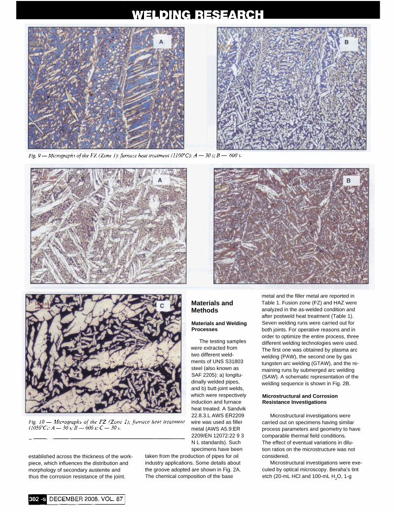
The furnace heat-treated specimens showed a homogeneous microstructure in the whole bead due to a more uniform temperature distribution across the thick- ness of the weld. The secondary austenite needles appear initially fine (i.e., Type I) and then tend to coarsen with increased annealing time. This microstructural evo- lution is more substantial at increased times and temperatures of the heat treat- ment (Figs. 9-11>. The micrograph of Fig. 10C shows, in particular, a magnification (500x) of the finer microstructure of a sample annealed for 30 s.
Further, the presence of the harmful σphase was encountered in samples held at 920°C for times exceeding 300 s (Fig. 12). In fact, when the DSS is annealed in the temperature range between 650° and 950°C, α phase can form after relatively
long holding times, as the eutectoid reac- tion δ→ γ 2 + σ takes place. The precipi- tation rate of σ phase is maximum for isothermal aging carried out at a temper- ature around 850°C. The higher the aging temperature, the coarser are the sigma precipitates (Refs. 18, 19). In particular, it was detected on the base metal a σ phase fraction of about 2 wt-% after aging for 5 min at 850°C (Ref. 20). The α/σ or γ/σ phase boundary acts as an initiation site for the metastable pitting because of the depletion of Cr and Mo around the σphase (Ref. 5).
The fraction of total secondary austen- ite was obtained by analyzing the digital mi- crographs taken on eight samples, each characteristic for a different heat treatment condition (temperature and time). The amount of total secondary austenite (i.e., both isolated and co-precipitated γ 2) was calculated as the difference between the fractions of austenites of the specimen in the as-welded condition (showing only pri- mary austenite) and after heat treatment. The results are summarized in Fig. 13.
Figure 13 shows the increment of sec- ondary austenite precipitation with the annealing time. Furthermore, it is shown that after 300 s the higher annealing tem- perature causes a more extensive volume increment of γ 2.
The corrosion tests have shown an in- crement of the pitting corrosion resistance at increasing holding times. The best re- sults were found at ll00°C, as shown in Fig. 14.
It was observed (Fig. 15) that corrosion started at the interface between ferrite and both secondary austenite precipitated at the grain boundary of primary austenite and the γ 2 precipitated into the ferrite grains.
The different pitting corrosion resis- tances of the furnace heat-treated speci- mens can be interpreted in terms of sec- ondary austenite precipitation. In fact, γ 2 is less resistant to pitting corrosion com- pared to other phases (PREN(γ 2) = 33, PREN(γ ) = 38) and introduces in the ma- terial new grain boundaries that are pref- erential nucleation sites for the chemical etching. These grain boundaries decrease with the increase in temperature and time of the heat treatment. Thus, it is was found that pitting corrosion is influenced not only by the depleted amount of Cr-Mo-N in γ 2 compared to the primary austenite composition (as found in previous works (Ref. 10)), but also by the amount of δ/γ 2 interfaces that are favorable sites for pit- ting nucleation.
The presence of intragranular chromium nitrides in heat-treated welded specimens was not detected by using light microscope (LOM) or ESEM. This seems in agreement with Ref. 21, in which it is shown that after the early stages of the re-
heating (10 s at 1000°-1100°C) most of such precipitation dissolves. That work proposes that N enrichment of ferrite as a result of ni- tride dissolution promotes secondary austenite precipitation; moreover, a hetero- geneous nucleation of intragranular austen- ite on the intragranular nitrides is proposed. In any case, such chromium nitrides are not seen after heat treatments longer than 10 s, so that their influence on corrosion proper- ties of heat-treated specimens is disre- garded in this work.
The different types of secondary austenite across the thickness of the in- duction heat-treated specimens, where a great amount of secondary austenite of Type I was observed near the head of the bead, may explain the reduction of pitting corrosion resistance in that zone. Finally, the as-welded samples showed better pit- ting corrosion resistance compared to the induction heat-treated ones. This behav- ior can be attributed to the absence of sec- ondary austenite in the as-welded samples and thus a minor amount of pitting nucle- ation sites. Following the experimental re- sults obtained in this work, better corro- sion resistance of the induction heat-treated pipes may be obtained by modifying the process parameters, aiming to reach higher annealing temperatures at both sides of the bead (e.g., about 1100°C on the bottom side and about 1050°C at the head).
Conclusions
This work studied the influence of postweld heat treatments on the corrosion resistance of a duplex stainless steel SAF 2205 and the comparison between post- weld induction heat treatment and con- ventional furnace heat treatment.
The main results of the experimental investigations are as follows:
a) As a result of metallographic investi- gations of FZ after postweld annealing, three phases were observed: primary ferrite (δ), primary austenite (γ ), and secondary austenite (γ 2). The postweld heat treatment of duplex stainless steels contributes to the creation of secondary (γ 2) austenite.
b) The induction heat-treated speci- mens showed a different morphology of secondary austenite across the section of the FZ (thin Widmanstatten-type needles ('γ 2-Type I') and coarse Widmanstatten- type needles ('γ 2-Type II')) with a preva- lence of γ 2 (Type I) in the outer surface of the pipe. This was attributed to the lower temperature reached in that zone com- pared to the one reached near the inner radius of the workpiece.
c) The furnace heat treatment showed that secondary austenite evolves from Type I to Type II according to time and temperature. The higher the temperature,

the faster and higher the pitting corrosion resistance reached by the specimens. A ra- tionale of this behavior could be the evo- lution of the morphology of secondary austenite from Type I to Type IIwith a fol- lowing reduction of the δ/γ 2 interface, where pitting corrosion generally starts.
These results, together with the calcu- lated temperature distribution in the induc- tion heat-treated specimens, explain the low pitting corrosion resistance found near the outer radius of the pipes and the better chemical properties of the as-welded sam- ples. Better results can be reached by in- creasing and adjusting the temperature across the thickness of the pipe by modify- ing the process parameters such as fre- quency, voltage, speed, or inductor length.
The final outcomes of the work are consequently:
1) The corrosion properties in postweld heat-treated duplex stainless steel SAF 2205 are related not only to the presence of the secondary austenite but also to its mor- phology, which in turn depends on the heat treatment parameters: a coarse secondary austenite induces better corrosion proper- ties compared to the finer one.
2) If induction heat treatment is carried out, a significant thermal gradient may arise across the thickness of the weld so that, ac- cording to the results of point 1, different corrosion properties may be found across the thickness of the joint.
Acknowledgments
The authors gratefully acknowledge the technical support of Giacomo Mazza- cavallo and Enrico Della Rovere, techni- cians of the metallurgical laboratory of DTG - University of Padova.
References
1. Kobayashi, D. Y., and Wolynec, S. 1999. Evaluation of the low corrosion resistant phase formed during the sigma phase precipitation in duplex-stainless steels. Materials Research 2(4):
2. Kordatos, J. D., Fourlaris, G., and Pa- padimitriou, G. 2001. The effect of cooling rate on the mechanical and corrosion properties of SAF 2205 (UNS 31803) duplex stainless steel welds. Scripta Materialia 4(3): 401-s to 408-s.
3. Bonollo, F., Tiziani, A., and Ferro, P. 2005. Microstructural evolution of duplex and su- perduplex stainless steels in relation to welding processes. La Metallurgia Italiana 97(2): 27-s to
4. Lopez, N., Cid, M., and Puiggali, M. 1999. Influence of σ-phase on mechanical properties and corrosion resistance of duplex stainless steels. Corrosion Science 41: 1615-s to 1631-s.
5. Park, C. J., Shankar Rao, V., and Kwon, H. S. 2005. Effects of sigma phase on the initiation and propagation of pitting corrosion of duplex stainless steel. Corrosion 61: 76-s to 83-s.
6. ASTM A928 /A928M - 08a, Standard Spec- ification for Ferritic/Austenitic (Duplex) Stainless Steel Pipe Electric Fusion Welded with Addition of Filler Metal (www. astm.org/Standards/A928. htm).
7. Young, M. C., Tsay, L. W., Shin, C.-S., and Chan, S. L. I. 2007. The effect of short time heat treatment on the fatigue crack growth of 2205 duplex stainless steel welds. International Jour- nal of Fatigue 29(12): 2115s to 2162-s.
8. Melotti, G., Bertelli, R., Zanesco, M., Calliari, I., and Ramous, E. 200.5. Solution treatment in duplex stainless steels. La Metal- lurgia Italiana 4: 39-s to 42-s.
9. Nowacki, J., and Lukojc, A. 2005. Structure and properties of the heat-affected zone of du- plex steels welded joints. Journal of Materials Pro- cessing Technology 164( 165): 1074-s to 1081-s.
10. Nilsson, J. O., Karlsson, L., and Ander- sson, J.-O.1995. Secondary austenite formation and its relation to pitting corrosion in duplex stainless steel weld metal. Matel: Sci. Tech. 11:
11. Garzon, C. M., and Ramirez, A. J. 2006.
239-s to 247-S.
38-S.
276-s to 283-s.
Growth kinetics of secondary austenite in the welding microstructure of a UNS S32304 du- plex stainless steel. Acta Materialia 54( 12):
12. Capello, E., Castelnuovo, M., Previtali, B., and Vedani, M. 2005. Laser welding and heat treatment of duplex stainless steels. La Metallurgia Italiana 2: 9-s to 14-s.
13. Nowacki, J., and Lukojc, A. 2006. Mi- crostructural transformations of heat affected zones in duplex steel welded joints. Materials Characterization 56(4-5): 436-s to 441-s.
14. Karlsson, L., and Pak, S. 1991. Weldingof duplex stainless steels - Properties of SMAW-, FCAW-, and SAW-welded joints. Proc. 'Stainless Steels 91 ', Chiba, Japan, The Iron and Steel In- stitute of Japan. 2, p. 1101-1108.
15. Meszaros, I. 2006. Magnetic characteri- sation of duplex stainless steel. Physica B.
16. Tavares, S. S. M., da Silva, M. R., and Neto, J. M. 2000. Magnetic property changes during embrittlement of a duplex stainless steel. Journal of Alloys and Compounds 313(1-2): 168-
17. Magnabosco, I., Ferro, P., Tiziani, A., and Bonollo, F. 2006. Induction heat treatment of a ISO C45 steel bar: Experimental and numerical analysis. Computational Materials Science 35(2):
18. Sieurin, H., and Sandstrom, R. 2007. Sigma phase precipitation in duplex stainless steel 2205. Mater: Sci. Eng. A 444(1-2): 271-s to
19. Huang, C.-S., and Shih, C.-C. 2005. Ef- fects of nitrogen and high temperature aging on phase precipitation of duplex stainless steel. Matel: Sci. Eng. A 402(1-2): 66-s to 75-s.
20. Ferro, P., Cervo, R., Bonollo, F., and Bertelli, R. 2007. Setup and implementation of a numerical model for the simulation of heat treatment of duplex stainless steels. Proc. Inter- national Conference Duplex 2007. Grado, Italy.
21. Ramirez, A. J., Brandi, S. D., and Lippold, J. C. 2004. Secondary austenite and chromium nitride precipitation in simulated heat affected zones of duplex stainless steels. Science and Tech- nology of Welding and Joining 9(4): 301-s to 313-s.
3321-s to 3331-s.
372(1-2): 181-s to 184-s.
s to 173-S.
98-s to 106-s.
276-S.