july 2016 pc-programmable 178-717-00k loop · pdf filepc-programmable loop display. typically...
TRANSCRIPT

PSD
PC-ProgrammableLoop Display
July 2016178-717-00K
PC
-Pro
gra
mm
able
Lo
op
Dis
pla
yPSD

Table of Contents
Introduction ............................................................................................................................................. 3
The PSD .......................................................................................................................... 3
Model and Serial Numbers ............................................................................................ 3
Specifi cations ................................................................................................. 3
Dimensions ..................................................................................................... 4
Confi guring the PSD ...................................................................................... 6
Installing the Confi guration Software .......................................................................... 6
Using the PC Program ................................................................................................... 7
Connecting the PSD to PC ............................................................................. 8
Necessary Equipment Table .......................................................................................... 8
Square Roots and the Curve Generator ....................................................... 9
Programming the PSD ................................................................................. 11
Site-Viewing the Confi guration ................................................................................... 11
Installation ..................................................................................................... 11
Recommended Ground Wiring Practices ................................................................... 11
Electrical Connections ................................................................................................ 11
CE Conformity .............................................................................................................. 11
Operation ...................................................................................................................... 12
Maintenance ................................................................................................................. 12
Customer Support ........................................................................................ 12
Intrinsic Safety .............................................................................................. 13
Appendix - A PSD in Safety Instrumented Systems ...................................... 14
Demand Moore Reliability 3
PSD
Input Accuracy:±0.012% of input scaleOverall Accuracy: The overall accuracy of the unit is the input accuracy. (±0.012% of input scale) It includes the combined effects of linearity, hys-teresis, repeatability, and adjustment resolution. It does not include ambient temperature effect.Stability: Error is in % of maximum span
Stability Input to Output
1yr 3yrs 5yrs mA 0.08 0.14 0.18
Resolution: 0.0028% of input scaleOver-Current Protection: 100mA maximumInput Overrange: 24mADigital Input Filter: User-programmable; 50 or 60 Hz
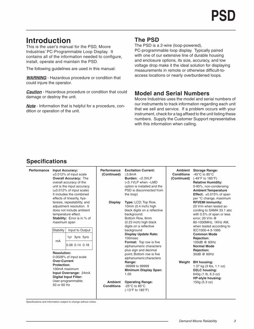
IntroductionThis is the user’s manual for the PSD, Moore Industries’ PC-Programmable Loop Display. It contains all of the information needed to confi gure, install, operate and maintain the PSD.
The following guidelines are used in this manual:
WARNING - Hazardous procedure or condition that could injure the operator.
Caution - Hazardous procedure or condition that could damage or destroy the unit.
Note - Information that is helpful for a procedure, con-dition or operation of the unit.
The PSDThe PSD is a 2-wire (loop-powered), PC-programmable loop display. Typically paired with one of our extensive line of durable housing and enclosure options, its size, accuracy, and low voltage drop make it the ideal solution for displaying measurements in remote or otherwise diffi cult-to-access locations or nearly overburdened loops.
Model and Serial NumbersMoore Industries uses the model and serial numbers of our instruments to track information regarding each unit that we sell and service. If a problem occurs with your instrument, check for a tag affi xed to the unit listing these numbers. Supply the Customer Support representative with this information when calling.
Specifi cationsExcitation Current: 3.8mABurden: <2.3VLP (<5.1VLP when –LMD option is installed and the PSD is disconnected from the loop)
Type: LCD; Top Row, 10mm (0.4 inch) high black digits on a refl ective background;Bottom Row, 6mm (0.23 inch) high black digits on a refl ective backgroundDisplay Update Rate: 100msecFormat: Top row is fi ve alphanumeric characters plus sign and decimal point; Bottom row is fi ve alphanumeric charactersRange: -99999 to 99999Minimum Display Span: 1.00
Operating Range:-25°C to 85°C(-13°F to 185°F)
Performance Performance(Continued)
Display
AmbientConditions
AmbientConditions
(Continued)
Weight
Storage Range:-45°C to 85°C(-49°F to 185°F)Relative Humidity:0-95%, non-condensingAmbient Temperature Effect: ±0.015% of span per °C change, maximumRFI/EMI Immunity:20 V/m when tested ac-cording to SAMA 33.1 abc with 0.5% of span or less error; 20 V/m @ 80-1000MHz, 1KHz AM, when tested according to IEC1000-4-3-1995Common Mode Rejection: 100dB @ 60HzNormal Mode Rejection: 30dB @ 60Hz
BH housing:1.37 kg (3 lbs, 1.1 oz)D2LC housing:640g (1 lb, 6.3 oz)HP-style housing: 150g (5.3 oz)
Specifi cations and Information subject to change without notice.

4 Demand Moore Reliability
PSDFigure 1. PSD Explosion-Proof BH Enclosure Dimensions
S D
61mm(2.4 in)83mm
(3.25 in)
62mm(2.45 in)
64mm(2.50 in)
66mm(2.58 in)
76mm(3.00 in)
43mm(1.70 in)
18mm(.70 in)
+IN -IN VIEW
PSD
602.78M M E T R
+IN -IN VIEW
PSD
602.78M M E T R
Figure 2. PSD Hockey-Puck Dimensions
Demand Moore Reliability 5
PSD
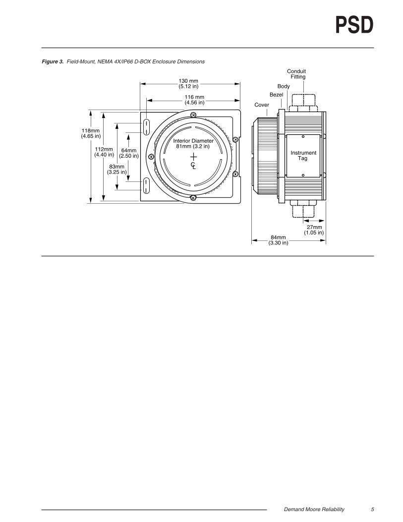
84mm(3.30 in)
118mm(4.65 in)
130 mm(5.12 in)
112mm(4.40 in)
83mm(3.25 in)
64mm(2.50 in)
CL
Interior Diameter81mm (3.2 in)
InstrumentTag
116 mm(4.56 in)
27mm(1.05 in)
ConduitFitting
Cover
Body
Bezel
Figure 3. Field-Mount, NEMA 4X/IP66 D-BOX Enclosure Dimensions
6 Demand Moore Reliability
PSD
Installing the Confi gurationSoftwareRefer to Table 1 for the equipment needed.
1. Insert the Moore Industries Interface Solution PC Confi guration Software CD into the CD drive of the PC. Access the CD and open the PSD SPD PC Confi guration Software folder.
2. Double-click the installation program located in the folder. Follow the prompts to correctly install the program.
Once the Confi guration Program is installed on the PC, the PSD can be connected to the loop or to equipment to simulate and calibrate input. You can then view and/or change the instrument’s parameters.
No PSD RequiredIt is not necessary to connect the display to a PC while creating confi guration fi les using the Confi guration Software. The Confi guration Program can be run without connecting a PSD, and most operating parameters can be set without benefi t of an attached unit.
This makes it easy to create a set of operating parameters, save and download them to one or more transmitters at a later time.
The PSD must be connected to the PC in order to: capture input, assign a tag, receive (via download) a confi guration fi le and save the confi guration fi le from the instrument’s memory.
Confi guring the PSDOne of the benefi ts of the PSD is that it has no internal or external controls to adjust or settings to change. All operating parameters are set using Moore Industries’ Intelligent PC Confi guration software.
Once these software settings are made, they are downloaded to the instrument in the form of a Confi guration File and stored in the unit’s non-volatile memory. You can choose to save a backup copy of the fi le on your PC hard drive or other external media. The transmitter communicates with the PC through a cable connection to the PC’s serial (COM) port or optional USB cable.
Default/Factory Confi gurations The following are the default factory settings for your unit:
Input: - 4-20mA - Filter: 60Hz - Damping Time: 0.0Display: - 0-100 PCT - Display Resolution: AUTO - Linearization Mode: Normal
Demand Moore Reliability 7
PSD
6
5
74
3
2 1
8
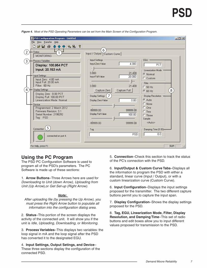
Using the PC ProgramThe PSD PC Confi guration Software is used to program all of the PSD’s parameters. The PC Software is made up of these sections:
1. Arrow Buttons–Three Arrows here are used for Downloading to Unit (down Arrow), Uploading from Unit (Up Arrow),or Get Set-up (Right Arrow).
Note: After uploading fi le (by pressing the Up Arrow), you must press the Right Arrow button to populate all
information into the confi guration dialog area.
2. Status–This portion of the screen displays the activity of the connected unit. It will show you if the unit is Idle, Uploading, Downloading, or Monitoring.
3. Process Variables–This displays two variables: the loop signal in mA and the loop signal after the PSD has converted it to the designated EGU.
4. Input Settings, Output Setings, and Device–These three sections display the confi guration of the connected PSD.
Figure 4. Most of the PSD Operating Parameters can be set from the Main Screen of the Confi guration Program.
5. Connection–Check this section to track the status of the PC’s connection with the PSD.
6. Input/Output & Custom Curve Tabs–Displays all the information to program the PSD with either a standard, linear curve (Input / Output), or with a custom linearization curve (Custom Curve).
6. Input Confi guration–Displays the input settings proposed for the transmitter. The two different capture buttons permit you to capture the input span.
7. Display Confi guration–Shows the display settings proposed for the PSD.
8. Tag, EGU, Linearization Mode, Filter, Display Resolution, and Damping Time–This set of radio buttons and edit boxes allow you to input different values proposed for transmission to the PSD.
8 Demand Moore Reliability
PSD
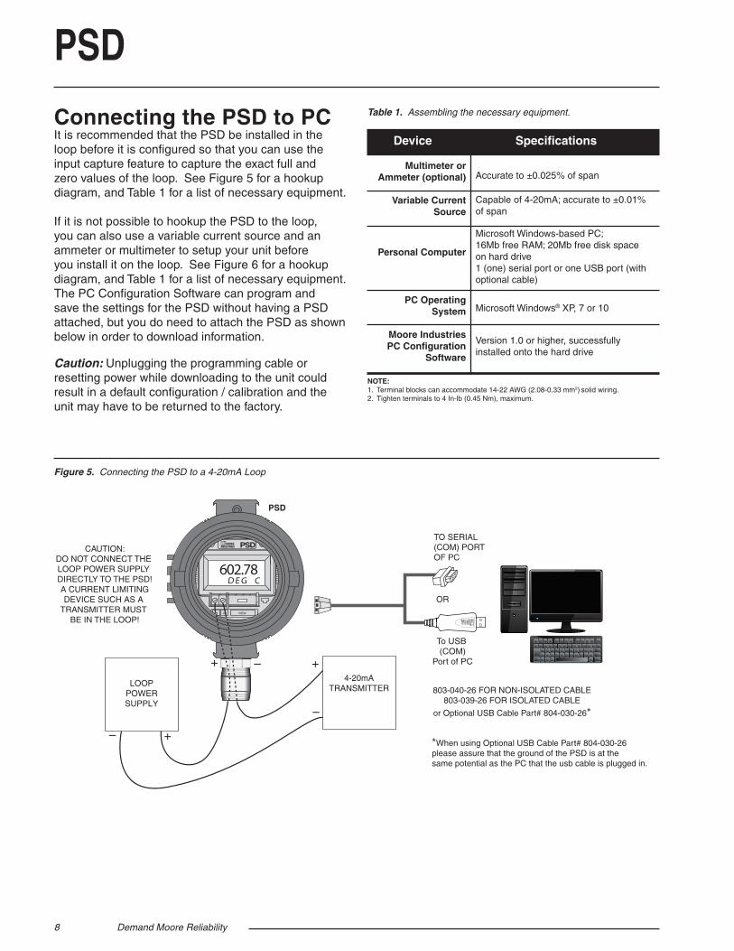
Figure 5. Connecting the PSD to a 4-20mA Loop
Connecting the PSD to PCIt is recommended that the PSD be installed in the loop before it is confi gured so that you can use the input capture feature to capture the exact full and zero values of the loop. See Figure 5 for a hookup diagram, and Table 1 for a list of necessary equipment.
If it is not possible to hookup the PSD to the loop, you can also use a variable current source and an ammeter or multimeter to setup your unit before you install it on the loop. See Figure 6 for a hookup diagram, and Table 1 for a list of necessary equipment. The PC Confi guration Software can program and save the settings for the PSD without having a PSD attached, but you do need to attach the PSD as shown below in order to download information.
Caution: Unplugging the programming cable or resetting power while downloading to the unit could result in a default confi guration / calibration and the unit may have to be returned to the factory.
Multimeter or Ammeter (optional)
Variable Current Source
Personal Computer
PC OperatingSystem
Moore Industries PC Confi guration
Software
Accurate to ±0.025% of span
Capable of 4-20mA; accurate to ±0.01% of span
Microsoft Windows-based PC;16Mb free RAM; 20Mb free disk space on hard drive 1 (one) serial port or one USB port (with optional cable)
Microsoft Windows® XP, 7 or 10
Version 1.0 or higher, successfully installed onto the hard drive
Device Specifi cations
Table 1. Assembling the necessary equipment.
NOTE:1. Terminal blocks can accommodate 14-22 AWG (2.08-0.33 mm2) solid wiring.2. Tighten terminals to 4 In-lb (0.45 Nm), maximum.
PSD
+IN -IN VIEW
PSD
602.78D E G C
+–
4-20mATRANSMITTER
+ – +
–
LOOPPOWERSUPPLY
TO SERIAL(COM) PORTOF PC
OR
803-040-26 FOR NON-ISOLATED CABLE803-039-26 FOR ISOLATED CABLE
or Optional USB Cable Part# 804-030-26*
*When using Optional USB Cable Part# 804-030-26 please assure that the ground of the PSD is at thesame potential as the PC that the usb cable is plugged in.
CAUTION:DO NOT CONNECT THE LOOP POWER SUPPLY DIRECTLY TO THE PSD!A CURRENT LIMITINGDEVICE SUCH AS A
TRANSMITTER MUST BE IN THE LOOP!
To USB (COM)
Port of PC
Demand Moore Reliability 9
PSD
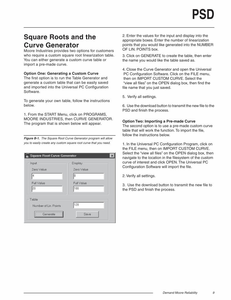
Square Roots and the Curve GeneratorMoore Industries provides two options for customers who require a custom square root linearization table. You can either generate a custom curve table or import a pre-made curve.
Option One: Generating a Custom CurveThe fi rst option is to run the Table Generator and generate a custom table that can be easily saved and imported into the Universal PC Confi guration Software.
To generate your own table, follow the instructions below.
1. From the START Menu, click on PROGRAMS, MOORE INDUSTRIES, then CURVE GENERATOR. The program that is shown below will appear.
Figure B-1. The Square Root Curve Generator program will allow
you to easily create any custom square root curve that you need.
2. Enter the values for the input and display into the appropriate boxes. Enter the number of linearization points that you would like generated into the NUMBER OF LIN. POINTS box.
3. Click on GENERATE to create the table, then enter the name you would like the table saved as.
4. Close the Curve Generator and open the Universal PC Confi guration Software. Click on the FILE menu, then on IMPORT CUSTOM CURVE. Select the “view all fi les” on the OPEN dialog box, then fi nd the fi le name that you just saved.
5. Verify all settings.
6. Use the download button to transmit the new fi le to the PSD and fi nish the process.
Option Two: Importing a Pre-made CurveThe second option is to use a pre-made custom curve table that will work the function. To import the fi le, follow the instructions below.
1. In the Universal PC Confi guration Program, click on the FILE menu, then on IMPORT CUSTOM CURVE. Select the “view all fi les” on the OPEN dialog box, then navigate to the location in the fi lesystem of the custom curve of interest and click OPEN. The Universal PC Confi guration Software will import the fi le.
2. Verify all settings.
3. Use the download button to transmit the new fi le to the PSD and fi nish the process.
10 Demand Moore Reliability
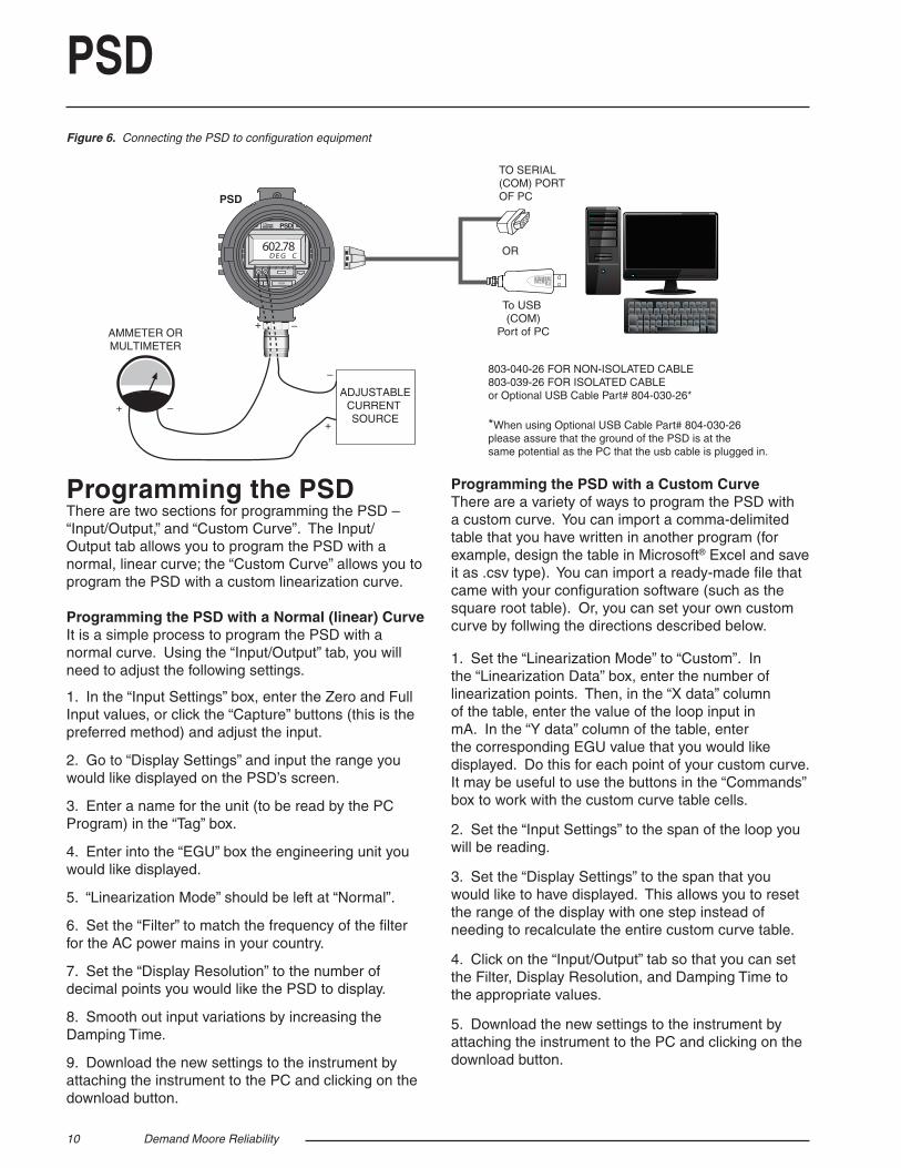
PSDFigure 6. Connecting the PSD to confi guration equipment
Programming the PSDThere are two sections for programming the PSD – “Input/Output,” and “Custom Curve”. The Input/Output tab allows you to program the PSD with a normal, linear curve; the “Custom Curve” allows you to program the PSD with a custom linearization curve.
Programming the PSD with a Normal (linear) CurveIt is a simple process to program the PSD with a normal curve. Using the “Input/Output” tab, you will need to adjust the following settings.
1. In the “Input Settings” box, enter the Zero and Full Input values, or click the “Capture” buttons (this is the preferred method) and adjust the input.
2. Go to “Display Settings” and input the range you would like displayed on the PSD’s screen.
3. Enter a name for the unit (to be read by the PC Program) in the “Tag” box.
4. Enter into the “EGU” box the engineering unit you would like displayed.
5. “Linearization Mode” should be left at “Normal”.
6. Set the “Filter” to match the frequency of the fi lter for the AC power mains in your country.
7. Set the “Display Resolution” to the number of decimal points you would like the PSD to display.
8. Smooth out input variations by increasing the Damping Time.
9. Download the new settings to the instrument by attaching the instrument to the PC and clicking on the download button.
Programming the PSD with a Custom CurveThere are a variety of ways to program the PSD with a custom curve. You can import a comma-delimited table that you have written in another program (for example, design the table in Microsoft® Excel and save it as .csv type). You can import a ready-made fi le that came with your confi guration software (such as the square root table). Or, you can set your own custom curve by follwing the directions described below.
1. Set the “Linearization Mode” to “Custom”. In the “Linearization Data” box, enter the number of linearization points. Then, in the “X data” column of the table, enter the value of the loop input in mA. In the “Y data” column of the table, enter the corresponding EGU value that you would like displayed. Do this for each point of your custom curve. It may be useful to use the buttons in the “Commands” box to work with the custom curve table cells.
2. Set the “Input Settings” to the span of the loop you will be reading.
3. Set the “Display Settings” to the span that you would like to have displayed. This allows you to reset the range of the display with one step instead of needing to recalculate the entire custom curve table.
4. Click on the “Input/Output” tab so that you can set the Filter, Display Resolution, and Damping Time to the appropriate values.
5. Download the new settings to the instrument by attaching the instrument to the PC and clicking on the download button.
PSD
+IN -IN VIEW
PSD
602.78D E G C
AMMETER ORMULTIMETER
+ –
ADJUSTABLECURRENT SOURCE
+ –
+
–
TO SERIAL(COM) PORTOF PC
OR
803-040-26 FOR NON-ISOLATED CABLE803-039-26 FOR ISOLATED CABLEor Optional USB Cable Part# 804-030-26*
*When using Optional USB Cable Part# 804-030-26 please assure that the ground of the PSD is at thesame potential as the PC that the usb cable is plugged in.
To USB (COM)
Port of PC
Demand Moore Reliability 11
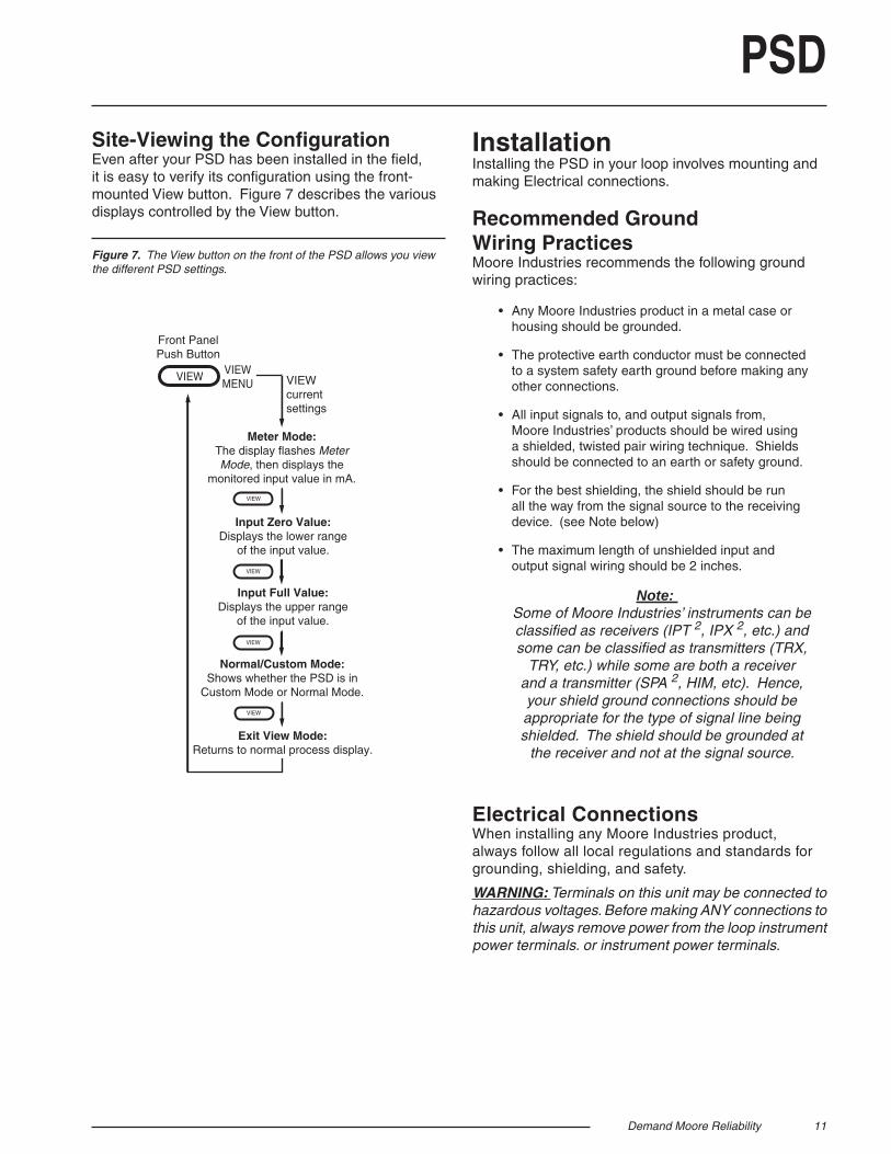
PSDSite-Viewing the Confi gurationEven after your PSD has been installed in the fi eld, it is easy to verify its confi guration using the front-mounted View button. Figure 7 describes the various displays controlled by the View button.
InstallationInstalling the PSD in your loop involves mounting and making Electrical connections.
Recommended Ground Wiring PracticesMoore Industries recommends the following ground wiring practices:
• Any Moore Industries product in a metal case or housing should be grounded.
• The protective earth conductor must be connected to a system safety earth ground before making any other connections.
• All input signals to, and output signals from, Moore Industries’ products should be wired using a shielded, twisted pair wiring technique. Shields should be connected to an earth or safety ground.
• For the best shielding, the shield should be run all the way from the signal source to the receiving device. (see Note below)
• The maximum length of unshielded input and output signal wiring should be 2 inches.
Note: Some of Moore Industries’ instruments can be classifi ed as receivers (IPT 2, IPX 2, etc.) and some can be classifi ed as transmitters (TRX,
TRY, etc.) while some are both a receiver and a transmitter (SPA 2, HIM, etc). Hence, your shield ground connections should be appropriate for the type of signal line being shielded. The shield should be grounded at
the receiver and not at the signal source.
Electrical Connections When installing any Moore Industries product, always follow all local regulations and standards for grounding, shielding, and safety.
WARNING: Terminals on this unit may be connected to hazardous voltages. Before making ANY connections to this unit, always remove power from the loop instrument power terminals. or instrument power terminals.
Meter Mode:The display flashes MeterMode, then displays the
monitored input value in mA.
Input Full Value:Displays the upper range
of the input value.
Input Zero Value:Displays the lower range
of the input value.
VIEW currentsettings
Front PanelPush Button
VIEWMENU
VIEW
Normal/Custom Mode:Shows whether the PSD is in
Custom Mode or Normal Mode.
VIEW
VIEW
VIEW
Exit View Mode:Returns to normal process display.
VIEW
Figure 7. The View button on the front of the PSD allows you view the different PSD settings.
12 Demand Moore Reliability
PSDInstallation Category All terminals are rated CAT I.
Equipment Ratings The PSD does not generate hazardous voltages, they provide a low current (4-20mA) or voltage (1-5V) input and a 4-20mA output. Products connected to the PSD should be designed to receive this type of input.
WARNING: If this unit is used in a manner not specifi ed by Moore Industries, the protection provided by the equipment may be impaired.
CE ConformityInstallation of any Moore Industries’ products that carry the CE marking must adhere to the guidelines in the Recommended Ground Wiring Practices section in order to meet the EN 61326 requirements set forth in the applicable EMC directive.
WARNING: If this unit is used in a manner not specifi ed by Moore Industries, the protection provided by the equipment may be impaired.
OperationOnce installed and programmed, PSD displays begin to operate immediately. Depending upon environmental conditions, they can be expected to operate unattended for extended periods of time.
MaintenanceMoore Industries suggests a quick check for terminal tightness and general unit condition every 6-8 months. Always adhere to any site requirements for programmed maintenance.
Customer SupportIf service assistance is ever required for an device in your application, refer to the back cover of this manual for the telephone numbers to Moore Industries’ customer service department.
If possible, make a note of the model number of the unit before calling. For fastest assistance, have the following information available: serial number, the job n5umber and purchase order number under which it was shipped.
Demand Moore Reliability 13
PSD
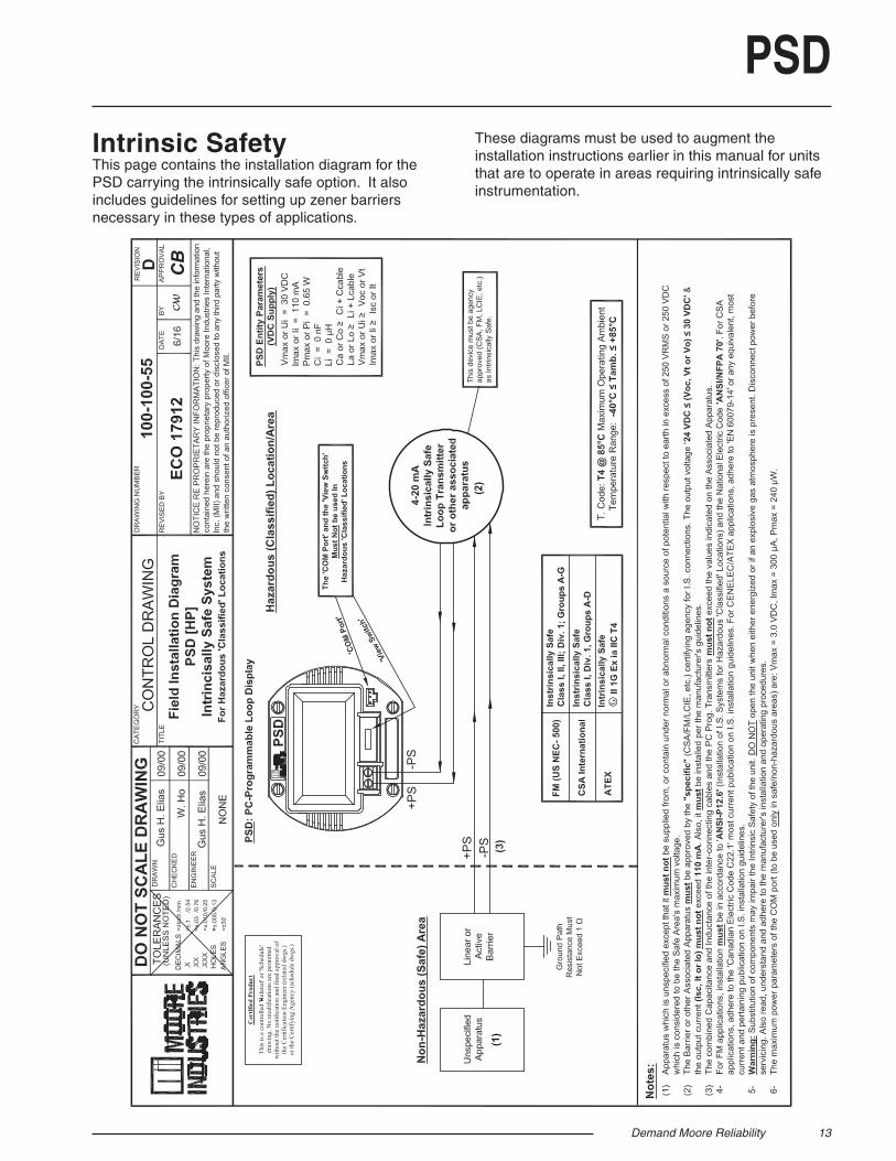
Intrinsic SafetyThis page contains the installation diagram for the PSD carrying the intrinsically safe option. It also includes guidelines for setting up zener barriers necessary in these types of applications.
These diagrams must be used to augment the installation instructions earlier in this manual for units that are to operate in areas requiring intrinsically safe instrumentation.
14 Demand Moore Reliability
PSD
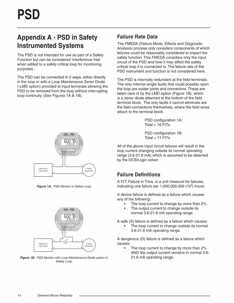
Appendix A - PSD in Safety Instrumented SystemsThe PSD is not intended for use as part of a Safety Function but can be considered ‘interference free’ when added to a safety critical loop for monitoring purposes.
The PSD can be connected in 2 ways, either directly in the loop or with a Loop Maintenance Zener Diode (-LMD option) provided at input terminals allowing the PSD to be removed from the loop without interrupting loop continuity. (See Figures 1A & 1B).
Figure 1A. PSD Monitor in Safety Loop
Figure 1B. PSD Monitor with Loop Maintenance Diode option in Safety Loop
+IN
+ +
+
-IN VIEW
PSD
602.78MMETR
Safety DCS/Logic Solver
4-20mATransmitter
+IN
+ +
+
-IN VIEW
PSD
602.78MMETR
Safety DCS/Logic Solver
4-20mATransmitter
Failure Rate DataThe FMEDA (Failure Mode, Effects and Diagnostic Analysis) process only considers components of which failures could be reasonably considered to impact the safety function. This FMEDA considers only the input circuit of the PSD and how it may affect the safety critical loop it is connected to. The failure rate of the PSD instrument and function is not considered here.
The PSD is internally redundant at the fi eld terminals. The only internal single faults that could possibly open the loop are solder joints and connectors. These are taken care of by the LMD option (Figure 1B), which is a zener diode attached to the bottom of the fi eld terminal block. The only faults it cannot eliminate are the fi eld connections themselves, where the fi eld wires attach to the terminal block.
PSD confi guration 1A: Total = 16 FITs
PSD confi guration 1B: Total = 11 FITs
All of the above input circuit failures will result in the loop current changing outside its normal operating range (3.6-21.6 mA) which is assumed to be detected by the DCS/Logic solver.
Failure Defi nitionsA FIT, Failure in Time, is a unit measure for failures, indicating one failure per 1,000,000,000 (109) hours.
A device failure is defi ned as a failure which causes any of the following: • The loop current to change by more than 2% • The output current to change outside its normal 3.6-21.6 mA operating range.
A safe (S) failure is defi ned as a failure which causes: • The loop current to change outside its normal 3.6-21.6 mA operating range.
A dangerous (D) failure is defi ned as a failure which causes: • The loop current to change by more than 2% AND the output current remains in normal 3.6- 21.6 mA operating range.

Demand Moore Reliability 15
PSDMethodologyThis FMEDA is designed to provide the end user with suffi cient information to construct a safety argument supporting the application of the subject device within a safety instrumented system (SIS). The FMEDA approach is consistent with the hardware requirements of IEC61508-2:2010.
For full certifi cation of the safety application, all requirements of IEC 61508 must be considered by the customer.
The failure rate and modes used in the analysis for the PSD were calculated using the Exida FMEDA tool. This tool contains a proprietary database derived from Telcordia, SN29500, HRBD5, MIL HDBK-217F, among others. It is expected that the data used and calculations employed return a result that is conservative against actual fi eld failure in environments with average stress.
The user is responsible for determining the fi tness of the data provided in this manual to any specifi c environment. For industrial plant sites with high environment stress or environment profi le that is different from the one given in the assumptions below, the user must multiply the provided data with an appropriate factor refl ecting the difference of the operating conditions from the reference conditions.
Assumptionsa. For the purpose of these assumptions ‘device’ will be taken to mean the ‘equipment’ which is the subject of this FMEDA. b. Only a single component failure will fail the entire ‘device’.c. Failure rates are constant; wear-out mechanisms are not included.d. Propagation of failures external to the device is not considered.e. All reasonably expected component failure modes are considered.f. The normal operating range of an analog transmitter is taken to be 3.6mA to 21.6mA.g. The reference ambient temperature is +40°C.h. The environmental profi le is average for an industrial environment and can be compared to the Ground Benign classifi cation of MIL-HDBK-217F and the reference environment of SN 29500 as well as Telcordia, HRD5, IEC 62380, RIAC 217+, among others.i. The input loop is a 4-20mA current loop.j. The input loop is monitored for excessively high and low loop current. In other words any out of range current will be detected as a fault.

WARRANTY DISCLAIMERTHE COMPANY MAKES NO EXPRESS, IMPLIED OR STATUTORY WAR-RANTIES (INCLUDING ANY WARRANTY OF MERCHANTABILITY OR OF FITNESS FOR A PARTICULAR PURPOSE) WITH RESPECT TO ANY GOODS OR SERVICES SOLD BY THE COMPANY. THE COMPANY DIS-CLAIMS ALL WARRANTIES ARISING FROM ANY COURSE OF DEALING OR TRADE USAGE, AND ANY BUYER OF GOODS OR SERVICES FROM THE COMPANY ACKNOWLEDGES THAT THERE ARE NO WARRANTIES IMPLIED BY CUSTOM OR USAGE IN THE TRADE OF THE BUYER AND OF THE COMPANY, AND THAT ANY PRIOR DEALINGS OF THE BUYER WITH THE COMPANY DO NOT IMPLY THAT THE COMPANY WARRANTS THE GOODS OR SERVICES IN ANY WAY. ANY BUYER OF GOODS OR SERVICES FROM THE COMPANY AGREES WITH THE COMPANY THAT THE SOLE AND EXCLUSIVE REM-EDIES FOR BREACH OF ANY WARRANTY CONCERNING THE GOODS OR SERVICES SHALL BE FOR THE COMPANY, AT ITS OPTION, TO REPAIR OR REPLACE THE GOODS OR SERVICES OR REFUND THE PURCHASE PRICE. THE COMPANY SHALL IN NO EVENT BE LIABLE FOR ANY CON-SEQUENTIAL OR INCIDENTAL DAMAGES EVEN IF THE COMPANY FAILS IN ANY ATTEMPT TO REMEDY DEFECTS IN THE GOODS OR SERVICES , BUT IN SUCH CASE THE BUYER SHALL BE ENTITLED TO NO MORE THAN A REFUND OF ALL MONIES PAID TO THE COMPANY BY THE BUYER FOR PURCHASE OF THE GOODS OR SERVICES.
RETURN PROCEDURES
ANY CAUSE OF ACTION FOR BREACH OF ANY WARRANTY BY THE COMPANY SHALL BE BARRED UNLESS THE COMPANY RE-CEIVES FROM THE BUYER A WRITTEN NOTICE OF THE ALLEGED DEFECT OR BREACH WITHIN TEN DAYS FROM THE EARLIEST DATE ON WHICH THE BUYER COULD REASONABLY HAVE DISCOVERED THE ALLEGED DEFECT OR BREACH, AND NO ACTION FOR THE BREACH OF ANY WARRANTY SHALL BE COMMENCED BY THE BUYER ANY LATER THAN TWELVE MONTHS FROM THE EARLIEST DATE ON WHICH THE BUYER COULD REASONABLY HAVE DISCOV-ERED THE ALLEGED DEFECT OR BREACH.
RETURN POLICYFor a period of thirty-six (36) months from the date of shipment, and under normal conditions of use and service, Moore Industries (“The Company”) will at its option replace, repair or refund the purchase price for any of its manufactured products found, upon return to the Company (transportation charges prepaid and otherwise in accordance with the return procedures established by The Company), to be defective in material or workmanship. This policy extends to the original Buyer only and not to Buyer’s customers or the users of Buyer’s products, unless Buyer is an engineering contractor in which case the policy shall extend to Buyer’s immediate customer only. This policy shall not apply if the product has been subject to alteration, misuse, accident, neglect or improper application, installation, or operation. THE COMPANY SHALL IN NO EVENT BE LIABLE FOR ANY INCIDENTAL OR CONSEQUENTIAL DAMAGES.
To return equipment to Moore Industries for repair, follow these four steps:
1. Call Moore Industries and request a Returned Material Authorization (RMA) number.
Warranty Repair – If you are unsure if your unit is still under warranty, we can use the unit’s serial number to verify the warranty status for you over the phone. Be sure to include the RMA number on all documentation.
Non-Warranty Repair – If your unit is out of warranty, be prepared to give us a Purchase Order number when you call. In most cases, we will be able to quote you the repair costs at that time. The repair price you are quoted will be a “Not To Exceed” price, which means that the actual repair costs may be less than the quote. Be sure to include the RMA number on all documentation.
2. Provide us with the following documentation:a) A note listing the symptoms that indicate the unit needs repairb) Complete shipping information for return of the equipment after repairc) The name and phone number of the person to contact if questions arise at the factory
3. Use suffi cient packing material and carefully pack the equipment in a sturdy shipping container.
4. Ship the equipment to the Moore Industries location nearest you.
The returned equipment will be inspected and tested at the factory. A Moore Industries representative will contact the person designated on your documentation if more information is needed. The repaired equipment, or its replacement, will be returned to you in accordance with the shipping instructions furnished in your documentation.
Specifi cations and Information subject to change without notice.© 2016 Moore Industries-International, Inc.
United States • [email protected]: (818) 894-7111 • FAX: (818) 891-2816
Australia • [email protected]: (02) 8536-7200 • FAX: (02) 9525-7296
Belgium • [email protected]: 03/448.10.18 • FAX: 03/440.17.97The Netherlands • [email protected]
Tel: (0)344-617971 • FAX: (0)344-615920
China • [email protected]: 86-21-62491499 • FAX: 86-21-62490635
United Kingdom • [email protected]: 01293 514488 • FAX: 01293 536852