keystone garage - images.atgstores.com filestep 2: layout six 8’ pressure treated 2”x4” floor...
TRANSCRIPT
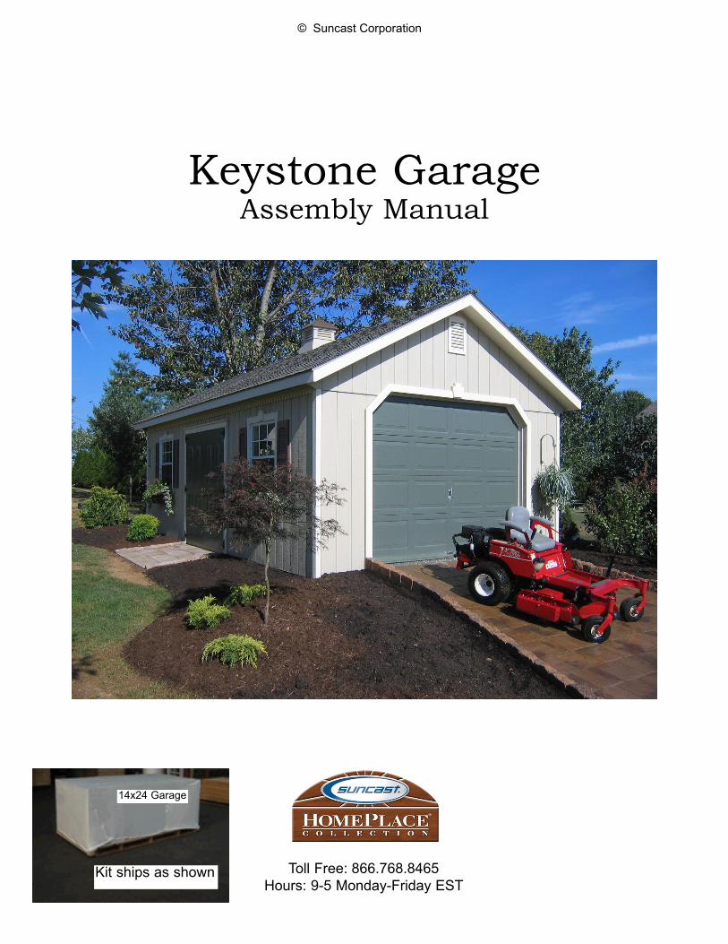
Keystone GarageAssembly Manual
© Suncast Corporation
Toll Free: 866.768.8465Hours: 9-5 Monday-Friday EST
Kit ships as shown
14x24 Garage

Find the assembly m
anual for this product atw
ww
.Hom
ePlaceStructures.com/m
anuals
AMISH ORIGINAL
KEYSTONE 14x24 GARAGEsp
ecification
s
This flexible building includes an optional heavy-duty floor, 2x4 construction, steep A-frame
roof style, insulated raised-panel steel house doors, dentil molding and keystone trim
pieces, 4 slider w
indows w
ith screens and shutters, 4 flower boxes, and screened w
ood vents. Can be built w
ith or without custom
er-supplied garage door.
2 Large Wrought
Iron Flower H
ooks
Boxed in12” G
ables
Factory Primed Trim
Diam
ond Plate Threshold
Factory Primed Siding
(Ready for Customer Supplied Paint)
Extra Strong 7’ High
Front and Back Walls
Optional G
arage Door
(Supplied by Customer)
Screened Wood Vents
1 Door K
eystone Trim Piece
4 Window
Keystone
Trim Pieces
Fancy Dentil M
olding
Assembled
Peak Height - 11’ 9”
Double Plyw
oodG
ussetsO
ptional Vented C
upola with Copper Roof
Rafter Ties
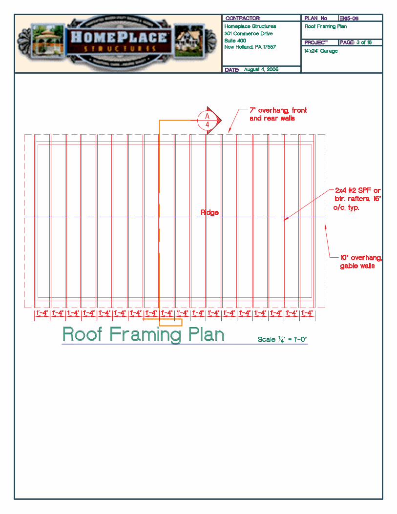
2x4 Rafters 16” O.C.
1/2” OSB Sheathing
Steep A-Fram
e Roof
Shingles (Supplied by Custom
er)
Four Large30x36 Alum
inumSlider W
indows
(with screens)
Four Vinyl
Flower B
oxes
Real Lock Set
Black A
ntique Hinges
Four Sets ofV
inyl Shutters
2x4 Sill Plate
24’w
ideInsulated R
aised Panel Double H
ouse Doors
(Doors can be placed on either end or the front)
13’8”deep
3/4” Exterior Grade 5-Ply D
ecking(w
ith optional floor)
Sidewalls 2x4s 16” O
.C.Treated Bottom
Plate(if purchased w
ithout floor)
Treated 2x4 Wood Ram
p(w
ith optional floor)

Keystone GarageAssembly Manual
© Suncast Corporation
revised 10/25/06
Please read through the entire manual before starting!
Note: It is very important that you have a solid, level site for the garden building. If the structure is being used as a garage for automobiles or other heavy items, the unit must be assembled on
a concrete pad.
When using tools and ladders always follow manufacturer’s recommended safety guidelines!
For proper layout for floor, walls, and roof, please refer to the drawings included throughout this manual and the set of engineered drawings included at end of manual. The pictures shown
in this manual may depict a different layout, if discrepancies occur always refer to drawings.
Tools Needed:Level
Screw GunHammer
Tape MeasureSkill SawSquare
Chalk LinePencil
5/16” Drill BitTin Snips
Caulking Gun
Other Items Needed:Approximately 8 gallons of paint
Approximately 20 Bundles of shinglesHeavy duty Silicone Caulk/Sealer
When your kit arrives, it should look like this. Inspect the package for any damage that may have occurred during shipping - dented corners, punctured plastic, etc. If the pack-age is damaged, alert HomePlace Structures immediately - 717.354.2333
14x24 Garage

Hardware & Fasteners
3” 12d NailsColor Code: Fluorescent
Green
Page 4
2-1/2” 7d NailsColor Code: Pink
2” 6d NailsColor Code: Orange
2” Trim NailsColor Code: Fluorescent
Yellow
1-1/2” Red Shutter ScrewsColor Code: Dark Blue
2” Black Hinge ScrewColor Code: Black
1” Pan Head Window ScrewsColor Code: Light Blue
1” Roofing NailsColor Code: Purple
The following fasteners are included with your kit. However, you will find the assembly process to pro-ceed much faster when using air powered tools and fasteners. When replacing hand fasteners with air
powered fasteners, always use a fastener equivalent.Note: The universal name for nail thickness is penny, abbreviated d. If you wish to purchase additional
nails at your local supplier, use this terminology to find the appropriate nails.
© Suncast Corporation


Optional Floor Assembly
Step 1: Cut open floor kit, cut metal bands, and remove top plywood sheet as shown.
Your floor kit should include all of the following parts:
Page 6
© Suncast Corporation
See drawings on previous page for correct layout.
If you did not purchase the optional floor, please proceed to page 8.
Pressure Treated 2”x4”:34 - 8' 28 - 65”
OSB pieces:48 - 3-1/2" x 23-1/2"
5/8” Plywood Flooring8 - 4’x8’ sheets, 2 - 4'x4' sheets2 - 20"x8', 2 - 20”x4’

Step 2: Layout six 8’ pressure treated 2”x4” floor plates, square joists at one end, and mark off for floor joists at 12” on center as shown.
Step 3: Layout floor as shown.Note: See attached drawing for correct layout.
Step 9: Fasten plywood sections to floor joists using 7d 2-1/4” galvanized nails spaced 8” apart. Note: It is important to properly align plywood at edges.
Step 4: Attach short floor joists to long floor joists using using 6d 2” nail and OSB pcs, keeping all pieces flush at top.
Step 5: Attach floor joists togeth-er at appropriate measurements using two 12d 3” nails per joist
Step 6: Attach outside band-board joists together as shown.
Step 7: Make sure floor is square. Floor is square when diagonal measurements are equal (approximately 27’5/8”).
Step 8: Layout plywood floor sections as shown.
page 7© Suncast Corporation
Tip: It is important to level floor before proceed-ing to next step.

Bottom Wall Plate Layout for Units without floor
Step 10: Cut open large package and remove packing materials repeating step 1.
Step 11: Remove top layer of 4’x8’ OSB roof sheeting and place to the side. Note: Unpack kit all the way down to layer 5.
Note: If you purchased the optional floor, please proceed to back wall layout and assembly page.
Step 12: Remove next layer of kit and set aside.
Step 13: Remove screws from 4’-2”x4” double wall plates and set aside.
Step 14: Remove all remaining pieces (excluding pressure treat-ed 2”x4” bottom wall plates)
Step 15: Measure a square pad at 13’8”x24’ and snap lines as shown. Make sure layout is square, see step 19.
page 8© Suncast Corporation

Step 16: Layout 6’ pressure treated bottom plates as shown.
Step 17: Mark and cut bottom plates to fit.
See step 17
Step 18: It is recommended to put a layer of clear silicone seal-er under bottom plates.
Step 19: Make sure bottom plate layout is square. It is square when diagonal measurements are equal.
Step 20: Fasten bottom plates to surface using concrete screws, tapcons, or fastener equivalent.
Bottom plate layout is complete.
page 9© Suncast Corporation
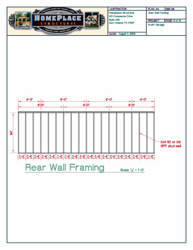

Back Wall Layout & Assembly
page 11© Suncast Corporation
Step 21: Layout top and bottom wall plates (top wall plate is a double 2x4 plate), square ends, measure and mark at 16” on center as shown.
Step 22: Layout 84”-2”x4” wall studs and fasten to top and bottom plates at marks using two 12d 3” nails per stud as shown.
Note: It is very important to align top of studs flush with top of wall plate.
See drawings on previous page for correct wall layout.

Step 23: Remove six 4’x90” siding sheets and layout on wall as shown.
Step 24: Start siding with overlap at corner with 1/2” overhang at end of wall.
Step 27: Mark and cut off excess siding as shown.
Step 25: Siding edge should center on wall stud. Fasten siding to walls using 7d 2-1/4” galvanized nails spaced 8” apart.
Step 26: Install next siding piece as shown, keeping groove reveal consistent with standard openings on sheet. Repeat to end of wall.
Step 28: Lift and set wall as shown.
Step 29: Fasten bottom wall plate to floor using 12d 3” nails every 8”. Fasten siding into floor using 7d 2-1/4” galvanized penny nails every 8”.
Step 30: Use extra wall stud to brace wall to floor as shown (make sure wall is plumb before fastening).
page 12
Siding to floor
wall plate to floor

© Suncast Corporation page 13
The window and door headers are comprised of extra strong 2x4 and plywood materials and require assembly. Please refer to the instructions below to assemble all headers for this unit.
H1: Layout two 2x4s and one plywood strip.
H2: Place plywood strip between 2x4s, align all edges, and fasten together using 2-1/2” galvanized 12d nails.
H3: Install header upright keeping 2x4 edge flush with wall studs as shown. Repeat these steps for each window and door header.
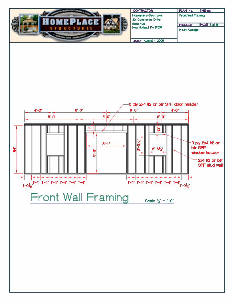
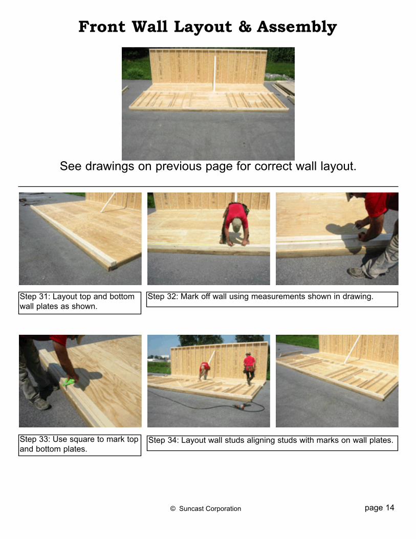
Front Wall Layout & Assembly
Step 31: Layout top and bottom wall plates as shown.
Step 33: Use square to mark top and bottom plates.
Step 32: Mark off wall using measurements shown in drawing.
Step 34: Layout wall studs aligning studs with marks on wall plates.
See drawings on previous page for correct wall layout.
page 14© Suncast Corporation

Step 35: Nail wall together using 12d 3” nails as shown.
Step 36: Begin with 4’x90” sid-ing pieces on either side of door, keeping 1/2” away from edge of 2x4. Nail 4’x90” across top only and only one nail at bot-tom doorway corner of siding piece.Note: Left side of door should have siding underlap.Note: Right side of door should have siding overlap.
Step 38: Before nailing rest of siding, make sure that door opening is square. Door is square when corner to corner diagonal measurements are equal (approximately 99”).
Step 37: Install 16-3/4”x4’ siding piece at top of door way - nail across top only.
page 15© Suncast Corporation
Siding Measurements:2 - 1’x90”, 4 - 4’x90” 2 - 16-3/4”x4’ (for top of door)
1/2” Reveal
3/4” Reveal
One Nail Here
4’x90”
1’x90”
16-3/4”x4’

Step 41: Lift and set wall repeat-ing steps from back wall. Fasten wall bottom plate to floor and siding to floor repeating step 30.
Step 39: Take remaining 16-3/4”x4’ door header siding, mark piece, cut siding piece to fit using mark and install as shown.
Step 42: Use extra wall stud to brace wall to floor as shown (make sure wall is plumb before fastening).
Step 40: Install remaining siding pieces.
page 16© Suncast Corporation


© Suncast Corporation
Side Wall Layout & Assembly
Step 43: Layout wall repeating steps on front and back walls, using the measurements shown in draw-ings. Note: All measurements should be taken from edge of front wall stud, do not measure from edge of siding.
Step 44: Set wall, align with front and back wall, and fasten to floors and adjoining walls as shown.
Note: This wall can be used for either the right or left side wall.
page 21
See drawings on previous pages for correct wall layout.

Page 22
Step 45: Make a mark at both ends of wall even with bottom of sid-ing and snap a line. Hammer 4 nails spaced approximately 2’ apart on line. Do not hammer nails all the way in, keep out - 3/4”.
© Suncast Corporation
Step 47: Install 4’x90” sheet of siding by resting it on nails along bot-tom. Align siding piece at top and edge of front wall stud (not with edge of siding), left siding splice should fall on the center of wall stud. Start with 20”x90” on opposite (right) wall.
Sidewall Siding Installation
Step 46: Layout three 4’x90”siding sheets and one 20”x90” sheet as shown.
Step 48: Make sure siding aligns properly at edge of wall. Nail off siding every 8” using 7d 2-1/4” galvanized nails.
Step 49: Each rafter set consists of two rafters and two gussets, with the exception of both end rafters which include only one gusset.
Rafter Assembly
Incorrect, birds mouth should be at bottom end of rafter.
If your unit configuration does not include a garage door, repeat previous steps on opposite gable wall making sure to use correct gable wall configuration. If your unit does include a garage door, please proceed to page 45 to install gable end wall with garage door opening.
Flush with front wall stud

page 23© Suncast Corporation
Step 50: First assemble two end rafters by fastening one rafter gusset to rafters using twelve 6d nails as shown. Assemble remaining rafters by fastening a rafter gusset to each side of rafter as shown.
Front & Back Soffit Installation
Step 51: Measure down 3-1/2” from top of wall and snap a line as shown.
Step 52: Install 1-1/2”x2-1/2”x8’ soffit strip, aligning bottom of strip with top of line as shown.
Two end rafters have one gusset

page 24© Suncast Corporation
Step 55: Mark last soffit piece and cut so soffit piece is flush with edge of gable wall siding as shown.
Step 57: Align end rafters with side edge of soffit, and in 1-1/2” in from front of soffit and fasten as shown.
Note: It is very important for rafter gusset to be facing towards interior of building.
Step 53: First soffit piece should pass end of wall stud 1/2” as shown (to ensure soffit piece is flush with edge of siding after gable siding is installed).
Step 54: Install remaining soffit pieces until reaching last piece.
Step 56: Front soffit is complete, repeat previous steps on back wall.
1-1/2” from edge of soffit
rafter gusset facing interior of building

page 25© Suncast Corporation
Step 58: Mark siding 8” from top of wall on both ends of gable wall and snap a line as shown.
Step 60: Install first gable siding piece, keeping piece aligned at ends and with chalk lines as shown.Note: Siding grooves should also align with grooves on lower wall.
Step 61: Install pre-cut gable siding brace at siding splice as shown.
Gable Siding Installation
Step 59: Starting with overlap at front, layout gable siding pieces as shown. Note: There is a left and right for end gable siding pieces. Front piece for left gable wall is 15” wide.
Step 62: Install remaining gable siding pieces repeating previous steps. Repeat on opposite gable wall.Note: If one gable wall has overhead door opening, see instructions on pages 45-47.
page 26© Suncast Corporation
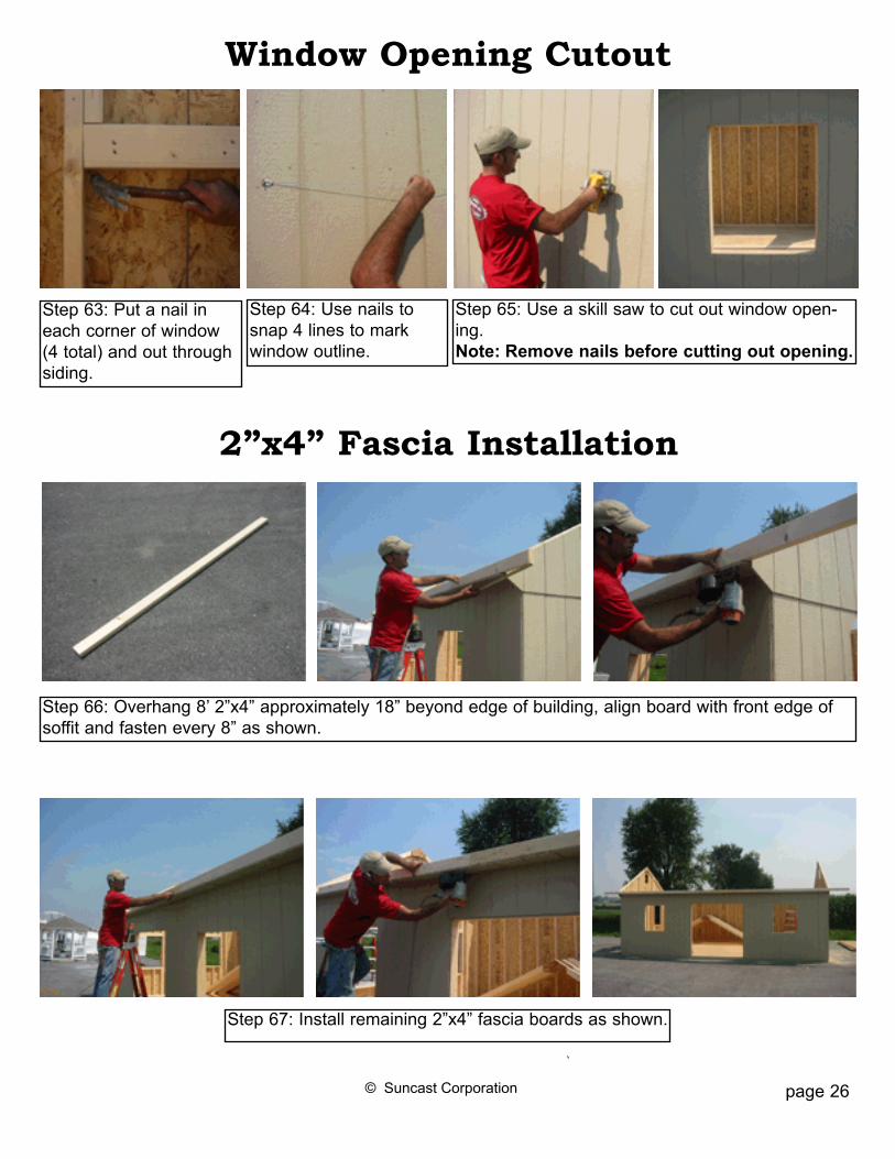
Step 66: Overhang 8’ 2”x4” approximately 18” beyond edge of building, align board with front edge of soffit and fasten every 8” as shown.
Step 67: Install remaining 2”x4” fascia boards as shown.
2”x4” Fascia Installation
Step 63: Put a nail in each corner of window (4 total) and out through siding.
Window Opening Cutout
Step 64: Use nails to snap 4 lines to mark window outline.
Step 65: Use a skill saw to cut out window open-ing. Note: Remove nails before cutting out opening.

page 28© Suncast Corporation
Step 69: Mark off fascia board every 16” from edge of end rafter as shown.
Step 71: Pull rafter tight against fascia board and fasten as shown. Toenail rafter into top of wall.
Rafter Installation
Step 68: Sight and straighten front and back walls using the wall brace as shown. Fasten brace to floor to keep wall straight. Note: Braces can be removed after roof sheeting has been installed.
Front & Back Wall Alignment
Step 70: Insert rafter behind fascia board and rest rafter on wall at birds mouth cutout as shown.

Step 75: Fasten roof sheet to rafter using 7d 2-1/4” nail every 8” as shown.
OSB Roof Sheeting Installation
Step 73: Layout three full sheets of OSB roof material for first row.
Step 74: Install first full sheet of OSB keeping sheet centered on raf-ters and resting against 2”x4” fascia board.
Step 76: Before fastening top of OSB sheeting mark every 16”.
page 29© Suncast Corporation
Step 72: Install remaining rafters repeating previous steps, fasten soffit board into rafters as shown.

Step 80: Layout gable overhang pieces as shown.White plywood goes on bottom, OSB goes on top.
Gable Overhang Assembly & Installation
Step 77: Fasten OSB to rafters making sure raf-ters are spaced evenly at 16” on center.
Step 78: Install remaining OSB pieces and repeat on back side.Note: Make sure to stagger OSB joints to maxi-mize roof strength.
Step 79: Paint building desired color (paint pur-chased separately).Note: Trim pieces included are primed white, you can paint the trim a different color to suit your taste. It is easiest to paint trim prior to installing.
Step 81: Assemble gable overhang keeping OSB flush at bottom and edges. Fasten OSB to rafters using 7d 2-1/4” nails every 8”. © Suncast Corporation page 30

© Suncast Corporation
Step 83: Install front gable overhang as shown using 3” 12d nails.
Gable Overhang Assembly & Installation p 2
page 31
Step 82: Gable overhang ready for installation.
Align flush with OSB roof sheet. Align at peak.
Fit tight against 2x4 fascia.
Fasten into end rafter.
Fasten through 2”x4” fascia board.

Fascia Trim Installation
Step 87: Overhang first fascia trim piece approximately 8”, align with OSB sheeting using a square, and fasten into 2”x4” using galvanized trim nails.
Step 85: Cut 2”x4” fascia flush at edge. Step 86: Layout 8’ primed fascia trim pieces.
Step 88: Align remaining fascia trim boards with previously installed boards and with OSB sheeting piece and fasten to 2”x4” as shown.
page 32© Suncast Corporation
Step 84: Repeat previous steps on back gable overhang and on opposite gable wall.
Toenail front and back together.

Step 91: Trace smaller fascia end piece, cut to fit, and install as shown.
Step 92: Repeat previous steps on back section, aligning angled cut pieces at center.
page 33© Suncast Corporation
Step 89: Front section complete, repeat on back wall.
Step 90: Align angled fascia piece at center of peak and with top of OSB sheeting and fasten to overhang end rafter.

Step 93: Install bottom of gable overhang, keeping painted side down as shown.
Step 94: Caulk at peak where painted plywood sections meet.
page 34© Suncast Corporation
Painted plywood
Step 95: Mark overhanging front fascia piece and cut flush with end fascia as shown.

page 35© Suncast Corporation
Step 99: Install painted trim piece on top of strip keeping all edges flush as shown.
Step 101: Attach painted 1x4 to 5/8” plywood piece using 2” trim nails as shown (keep all edges flush).
Step 96: Layout door trim pieces as shown.
Door Trim Material List:2 - 3-1/2”x73-1/2” 5/8 plywood1 - 3-1/2”x78-3/4” 5/8 plywood2 - 1”x4”x73-1/2” painted trim1 - 1”x4”x78-3/4” painted trim1 - 1”x3”x81” painted trim
Door Trim Installation
Step 97: Make a mark 3/4” above door header at both ends of door opening.
Step 98: Fasten unpainted door trim strip aligning with edge of siding and with mark.
Step 100: Repeat previous steps making sure door trim is spaced 71-3/4” apart.
Step 102: Attach 1x3x81” flat on top of 1x4 trim piece as shown.
Step 103: Install top door trim piece and properly align as shown.

Step 104: Layout corner trim pieces as shown.
Corner Trim Installation
Step 105: Install 80” corner trim piece on front using 2” trim nails as shown.
Step 106: Install 77-1/4” corner trim piece on side as shown. Repeat on all four corners.
77-1/4”80”
Step 107: Install dentil molding from left to right using 2” trim nails as shown.Note: You will need to cut the final piece to fit.
Dentil Molding Installation
© Suncast Corporation page 36

Step 109: Layout window trim pieces as shown.
Material List:2 - 37-5/8” 1x3 side pieces1 - 30-7/8 short point 1x3 bottom1 - 30-7/8” short point 1x4 top
Step 111: Install top and bottom window trim keeping short points flush with side trim.
Step 108: Install windows as shown using 1” pan head screws. It is strongly recommended to seal behind window flanges with clear silicone caulk.
Window & Window Trim Installation
Step 112: Repeat previous steps on all windows.
Step 110: First install side window trim keeping flush with window at top and bottom. Fasten trim with 2” trim nails.
page 37© Suncast Corporation
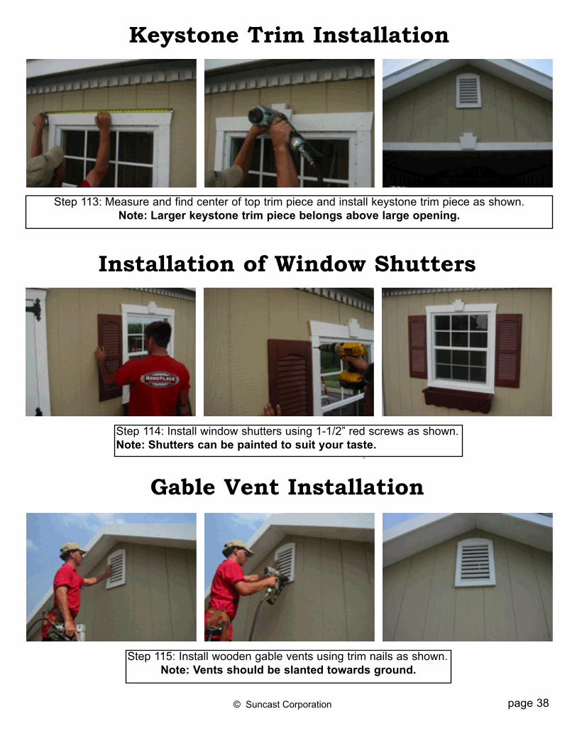
Step 115: Install wooden gable vents using trim nails as shown.Note: Vents should be slanted towards ground.
Gable Vent Installation
page 38© Suncast Corporation
Step 114: Install window shutters using 1-1/2” red screws as shown. Note: Shutters can be painted to suit your taste.
Installation of Window Shutters
Step 113: Measure and find center of top trim piece and install keystone trim piece as shown. Note: Larger keystone trim piece belongs above large opening.
Keystone Trim Installation
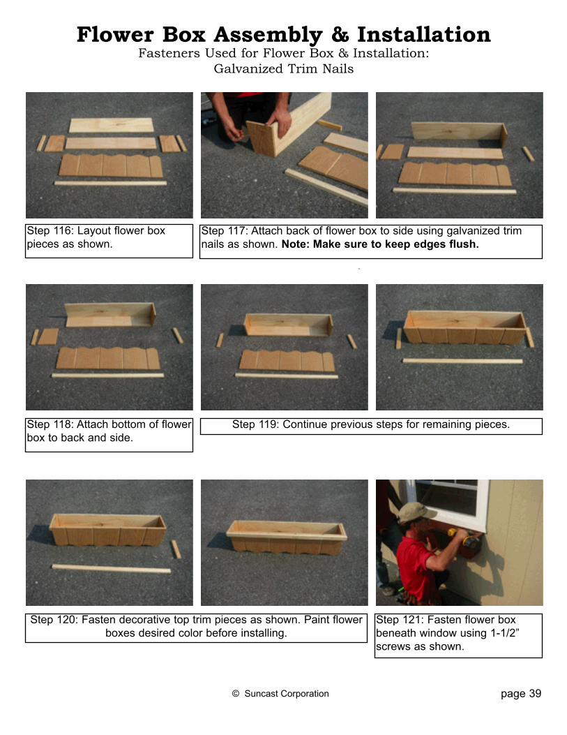
Step 120: Fasten decorative top trim pieces as shown. Paint flower boxes desired color before installing.
Step 116: Layout flower box pieces as shown.
Flower Box Assembly & InstallationFasteners Used for Flower Box & Installation:
Galvanized Trim Nails
Step 121: Fasten flower box beneath window using 1-1/2” screws as shown.
Step 117: Attach back of flower box to side using galvanized trim nails as shown. Note: Make sure to keep edges flush.
Step 118: Attach bottom of flower box to back and side.
Step 119: Continue previous steps for remaining pieces.
© Suncast Corporation page 39

© Suncast Corporation
Step 122: Layout doors putting door with latch hole cutout on the right.
Step 124: Install opposite door repeating previous steps as shown.Note: It is important to keep the reveal at top of door consistent the whole way across top of door.
Door Installation
Step 123: Starting with left door, install doors keeping door tight against side and 1/4” reveal at top. Use 2” black hinge screws as shown.
Step 125: Mark location of inte-rior door latch by tapping latch into top and bottom headers as shown.
page 40
Step 126: Drill out 5/16” hole for top and bottom latch as shown. Step 127: Install door latch fol-lowing directions included with latch.

Step 128: Layout 6’ treated ramp pieces as shownNote: If you did not purchase the optional floor, the ramp is not included.
Step 131: Measure in 12” from each end as shown.
Ramp Assembly & Installation
Step 129: Find center of only one 2x4 treated ramp piece and cut in half for ramp bottom brace.
Step 130: Layout ramp pieces and make sure edges are pre-cisely straight as shown.
Step 132: Fasten cut bottom braces to bottom of ramp using 16p 3” nails as shown.
page 41© Suncast Corporation
Step 133: Fasten bottom door kick strip beneath door using 7d 2-1/4” galvanized nails as shown.
Continued...
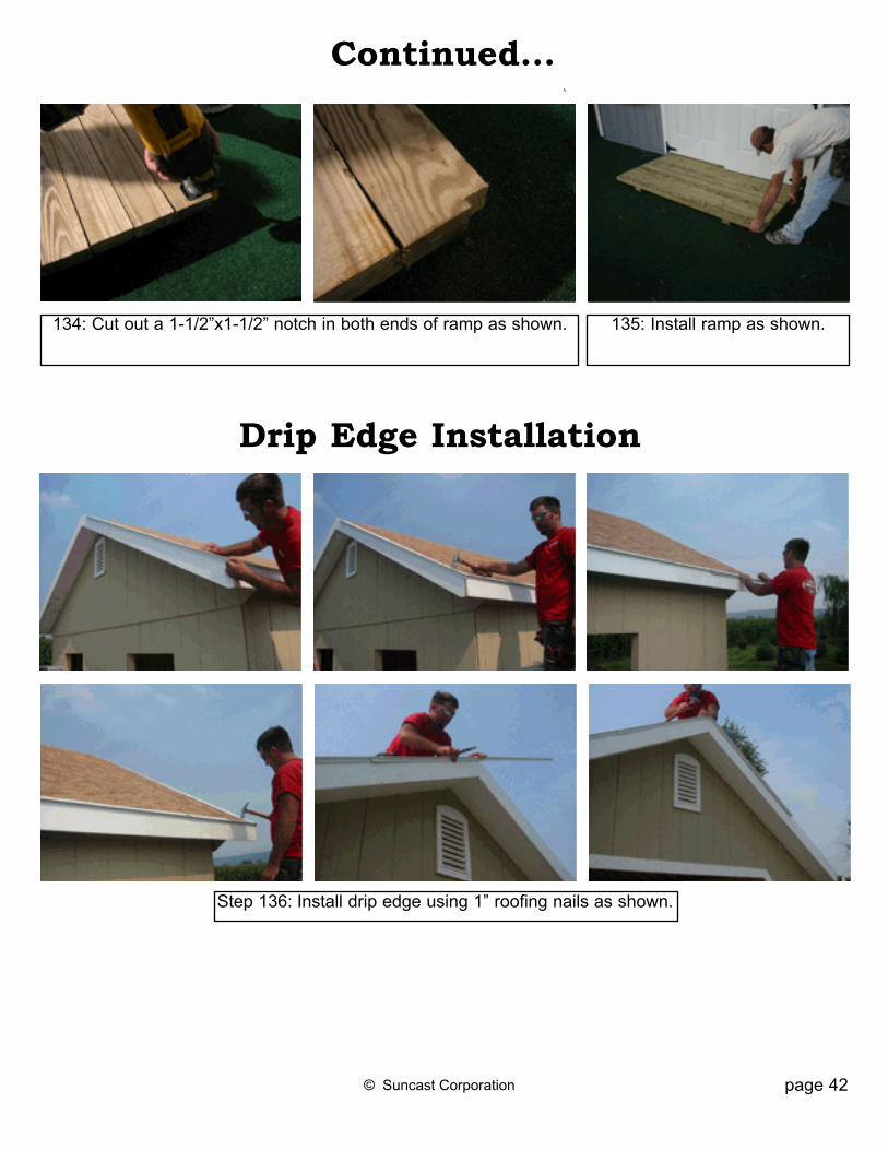
134: Cut out a 1-1/2”x1-1/2” notch in both ends of ramp as shown.
Drip Edge Installation
135: Install ramp as shown.
© Suncast Corporation page 42
Step 136: Install drip edge using 1” roofing nails as shown.

Rafter Tie Installation
Hurricane Clip Installation
Step 137: Use remaining wall studs as rafter ties. Install rafter ties with 12d 3-1/2” nails as shown.Note: Space rafter ties evenly throughout building.
© Suncast Corporation page 43
Step 138: Install hurricane clips on each rafter as shown.
Flower Hook Installation
Step 139: Install flower pot hooks where desired using black screws.

page 44
Door Stop Installation
Step 140: Install door stop on both doors as
© Suncast Corporation
Optional Garage Door Layout & Assembly
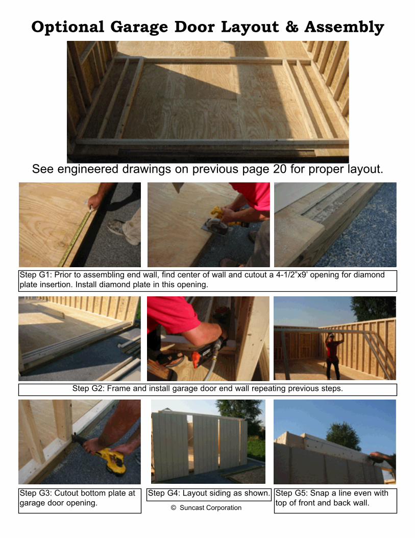
Step G1: Prior to assembling end wall, find center of wall and cutout a 4-1/2”x9’ opening for diamond plate insertion. Install diamond plate in this opening.
See engineered drawings on previous page 20 for proper layout.
© Suncast Corporation
Step G2: Frame and install garage door end wall repeating previous steps.
Step G3: Cutout bottom plate at garage door opening.
Step G4: Layout siding as shown. Step G5: Snap a line even with top of front and back wall.

Step G6: Install siding, keep-ing top of siding flush with line snapped on previous step.
Step G8: Install gable roof siding after installing end rafter repeating steps from opposite gable wall. Cut out excess siding at top of door opening.
Step G7: Cutout overhead door opening using a skill saw or router.
Step G9: Install trim filler strips at border of overhead door opening as shown.
page 46© Suncast Corporation

Step G11: Install inside filler trim strips as shown.
page 47© Suncast Corporation
Step G12: Install overhead door exterior trim pieces as shown.
G10: Repeat on opposite side of door.

Optional Cupola Installation
Step 7: Position cupola on center of roof and fasten to roof using 3 inch screws. Fill holes with silicone caulk to prevent roof from leaking.Note: To utilize venting for cupola, cut out an 8”x8” hole in center of roof, prior to installing cupola. Attach a screen piece over hole to keep out insects.
Step 1: Take 2 scrap wood pieces approximately 24” long and fasten tightly together with one screw, so boards pivot when applying pressure.
Step 9: Attach roof to base using screws attached to roof.
Step 3: Straddle the roof with each board, making sure each board is flat against the roof. Mark boards with pen-cil for cutting template.Note: Mark front and back board.
Step 4: Find center of cupola and mark lightly with pencil.
Step 5: Align marks on bottom board with edges of top board and make a cut line from each corner to center line.
Step 2: Measure from end of building, find center of roof and mark.
Step 6: Cut out roof line by starting at corners and cutting to center. Repeat steps 4-6 on opposite side of cupola.Note: When marking opposite side of cupola base, make sure that front and back board match with previous side.
Step 8: Place cupola roof on top of base. Note: Remove shrink wrap from cop-per after step 9 to protect copper from oils on skin.
Fron
t
Toll Free: 866.768.8465Hours: 9-5 Monday-Friday EST
Amish Handcrafted Gazebos, Garden Buildings, Garages, Playhouses, & Playsets

Congratulations...
... your Keystone Garage is now ready for shingle application.
Note: Follow shingle manufacturer’s application recom-mendations.
© Suncast Corporation