l 6 ct physics
TRANSCRIPT

INTRODUCTION TO CT PHYSICS
Shahid Younas Lecture 6

Computed Tomography
Shahid Younas Lecture 6
Which is true for 5th Generation CT Scanner
A. does not use a conventional x-ray tube
B. Multiple array of detectors
C. Bed moves with variable pitch
D. useful for cardiology and nephrology
E. Fast scanning but negligible radiation dose

Computed Tomography
Shahid Younas Lecture 6
What is the alternative name for the 5th Generation CT
A. CBET
B. Cine CT
C. Cardiac CT
D. Rotate / Rotate CT
E. Stationary / Rotate CT

Computed Tomography
Shahid Younas Lecture 6
What special reconstruction method is used in Helical CT?
A. Simulation
B. Matriculation
C. Intercalation
D. Interpolation
E. Manipulation

Computed Tomography
Shahid Younas Lecture 6
Which is the in-correct statement for 6th Generation CT?
A. Volume scanning
B. Short scan time
C. Helical scanner
D. Spiral scanner
E. Inconsistent set of data

Computed Tomography
Shahid Younas Lecture 6
Which one is in-correct about in Helical Scanning?
A. Pitch = table feed per rotation/collimation
B. The larger the table feed, the faster a body scanned
C. use of less contrast agent
D. increases patient throughput
E. No slip ring technology
Computed Tomography
Shahid Younas Lecture 6
The 3rd and 4th Generation CT Scanners moves continuously due to circular contact with sliding brushes decreasing the scanning time because of
A. Multiple detector array
B. Non conventional X ray tube
C. Wide Fan Beam Geometry
D. Continuous arc of detectors around patient
E. Slip Ring contacts
Computed Tomography
Shahid Younas Lecture 6
Which one describes the Seventh generation CT scanner?
A. Rotate / Translate Pencil Beam
B. Rotate / Translate Narrow Fan Beam
C. Rotate / Rotate Wide Fan Beam
D. Rotate / Stationary
E. Multiple Detector Array

Computed Tomography
Shahid Younas Lecture 6
Seventh generation CT scanners were based on ?
A. Effective usage of x-ray
B. Narrow collimation
C. Narrow Fan Beam
D. Small detector size
E. Low Pitch high contrast

CT Detectors- XENON DETECTOR
Shahid Younas Lecture 6
CT Detectors
1. Xenon
2. Solid State
3. Multiple detector array

CT Detectors- XENON DETECTOR
Shahid Younas Lecture 6

CT Detectors- XENON DETECTOR
Shahid Younas Lecture 6
Xenon detector arrays are a series of highly directional
xenon filled ionization chambers.
Current ~ Intensity

CT Detectors- XENON DETECTOR
Shahid Younas Lecture 6
Do you remember the detection efficiency of detectors? Which is
the best gas detectors or solid state detectors?
High-pressure xenon detectors provide detection efficiencies of about 50%. The detection efficiency of solid-state detectors
used in CT is about 80%.
CT Detectors- XENON DETECTOR
Shahid Younas Lecture 6
Although a gaseous detector does not have the same detection
efficiency as a solid one, the detector can be made very thick
(e.g. 6 cm) to compensate in part for its relatively low density.

CT Detectors- XENON DETECTOR
Shahid Younas Lecture 6
The metal septa that separate the individual xenon detectors
can also be made quite thin, and this improves the geometric
efficiency by reducing dead space between detectors..
CT Detectors- XENON DETECTOR
Shahid Younas Lecture 6
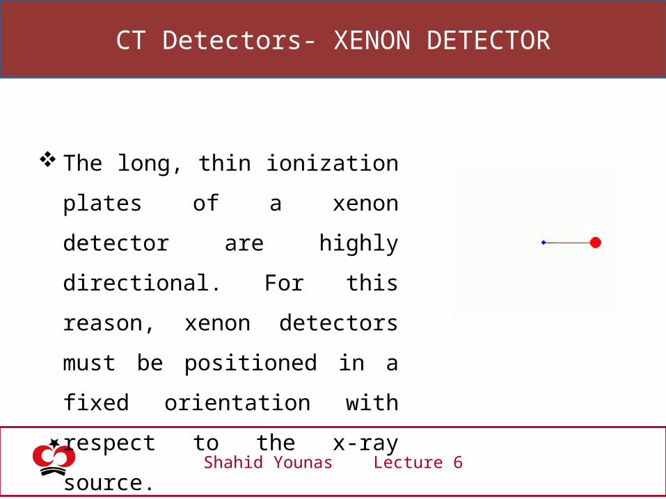
The long, thin ionization plates of a
xenon detector are highly directional.
For this reason, xenon detectors must
be positioned in a fixed orientation
with respect to the x-ray source.

CT Detectors- XENON DETECTOR
Shahid Younas Lecture 6

CT Detectors- XENON DETECTOR
Shahid Younas Lecture 6
Xenon detectors are highly directional. Can we use it in Fourth
Generation CT Scanners?
The long, thin ionization plates of a xenon detector are highly
directional. For this reason, xenon detectors must be positioned
in a fixed orientation with respect to the x-ray source.

CT Detectors- XENON DETECTOR
Shahid Younas Lecture 6
Therefore, xenon detectors
cannot be used for fourth-
generation scanners, because
those detectors have to
record x-rays as the source
moves over a very wide
angle.

CT Detectors- XENON DETECTOR
Shahid Younas Lecture 6
Xenon detector technology has
been surpassed by solid-state
detectors, and its use is now
relegated to inexpensive CT
scanners.

CT Detectors
Shahid Younas Lecture 6
Solid State Detectors
CT Detectors- Solid State Detectors
Shahid Younas Lecture 6
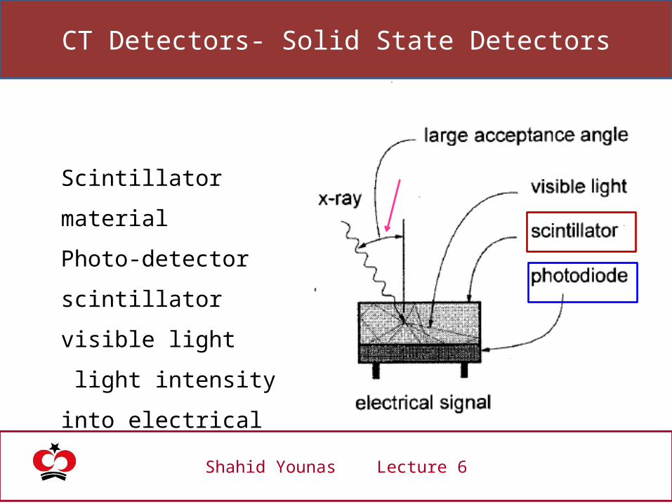
Scintillator material
Photo-detector
scintillator visible light
light intensity into
electrical

CT Detectors- Solid State Detectors
Shahid Younas Lecture 6
CdWO4
Yttrium
Gadolinium ceramics
Do you know which solid state detectors are used in present day
CT Scanners?
CT Detectors- Solid State Detectors
Shahid Younas Lecture 6
Because of density and effective atomic number solid-state
detectors typically have better x-ray absorption efficiency.
However, to reduce crosstalk between adjacent detector
elements, a small gap between detector elements is necessary,
and this reduces the geometric efficiency somewhat.
CT Detectors- Solid State Detectors
Shahid Younas Lecture 6
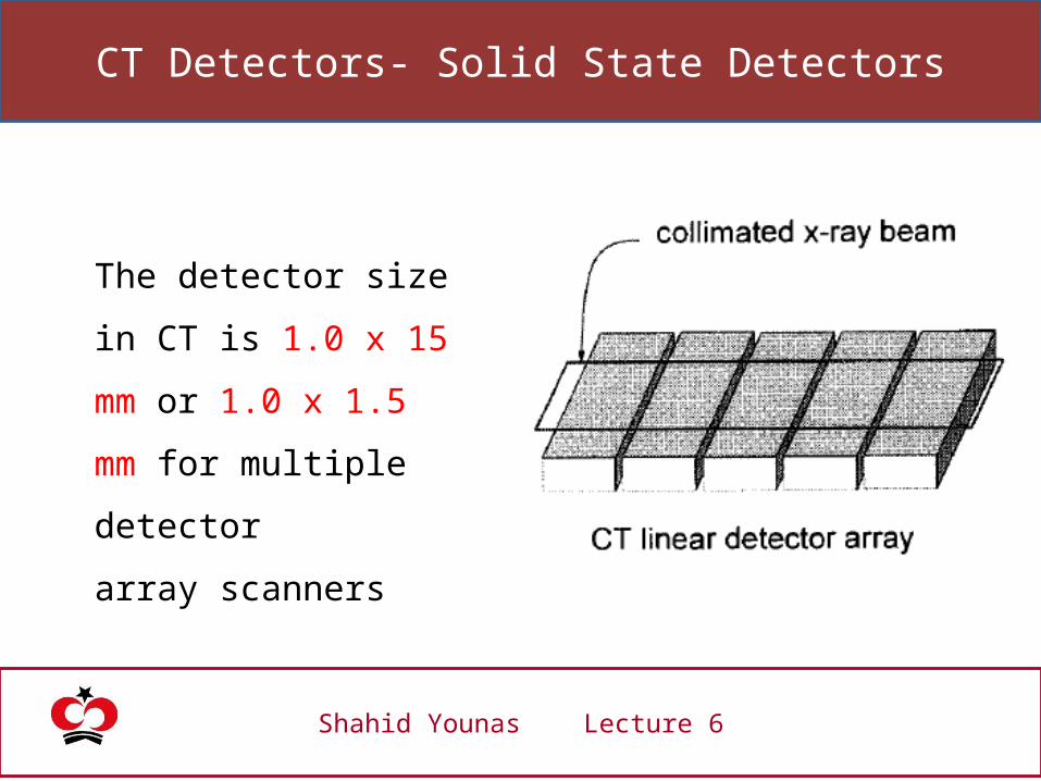
The detector size in CT is
1.0 x 15 mm or 1.0 x 1.5
mm for multiple detector
array scanners

CT Detectors- Solid State Detectors
The top surface of a solid-
state CT detector is
essentially flat and therefore
is capable of x-ray detection
over a wide range of angles,
unlike the xenon detector.
CT Detectors- Solid State Detectors
Solid-state detectors are
required for fourth-
generation CT scanners,
and they are used in most
high-tier third-generation
scanners as well.

CT Detectors- Solid State Detectors

CT Detectors- Multiple Detector Array
Shahid Younas Lecture 6
The multiple detector
array is an assembly of
multiple solid-state
detector array modules.

CT Detectors- Multiple Detector Array
With a traditional single detector
array CT system, the detectors
are quite wide (~15 mm) and the
adjustable collimator determines
slice thickness.

CT Detectors- Multiple Detector Array
Slice width is determined by
the detectors not by the
collimator (collimator does
limit the beam to the total
slice thickness).

CT Detectors- Multiple Detector Array
slice width is determined by
grouping one or more detector units
together.
The individual detector elements are
1.25 mm wide, and there are 16
contiguous detectors across the
module.
CT Detectors- Multiple Detector Array
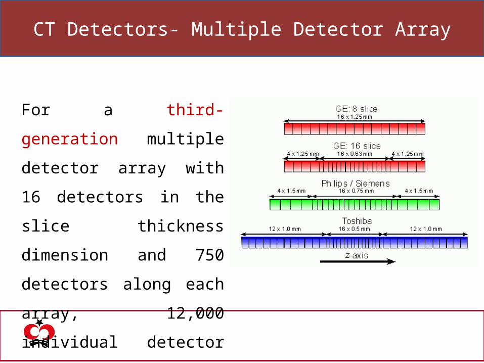
For a third-generation multiple
detector array with 16
detectors in the slice thickness
dimension and 750 detectors
along each array, 12,000
individual detector elements
are used.

CT Detectors- Multiple Detector Array
The detector dimensions are
referenced to the scanner's
isocenter - the point at the
center of gantry rotation.

CT Detectors- Multiple Detector Array
All currently planned multiple
detector array scanners make
use of third-generation
geometry to reduce the number
of detector hence cost.

Detail of Acquisition

Slice Thickness: Single Detector Array Scanners
Shahid Younas Lecture 6
The slice thickness in single detector array CT systems is
determined by the physical collimation of the incident x-
ray beam with two lead jaws.
As the gap between the two lead jaws widens, the slice
thickness increases.

Slice Thickness: Single Detector Array Scanners
Shahid Younas Lecture 6
The width of the detectors in the single detector array places an
upper limit on slice thickness.
Opening the collimation beyond this point would do nothing to
increase slice thickness, but would increase both the dose to the
patient and the amount of scattered radiation.

Slice Thickness: Single Detector Array Scanners
Shahid Younas Lecture 6
Increased slice thickness increases the number of x ray detected
BUT
Signal to noise ration increase linearly
Slice Thickness: Single Detector Array Scanners
Shahid Younas Lecture 6
Larger slice thicknesses yield better contrast resolution (higher
SNR) with the same x-ray techniques,
but
the spatial resolution in the slice thickness dimension is reduced.

Slice Thickness: Single Detector Array Scanners
Shahid Younas Lecture 6
Thin slices improve spatial resolution in the thickness
dimension and reduce partial volume averaging.
For thin slices, the mAs of the study protocol usually is
increased to partially compensate for the loss of x-ray photons
resulting from the collimation.

Self Explanatory!