low power tv transmitter mini prjct ppt
DESCRIPTION
Studying low power TV transmitter. In this, transmission of signals are possible from cable TV and DTH service and through Local area transmitter. Local area transmission includes High Power Transmitters. Low Power Transmitters and Very Low power Transmitters. Low Power transmitters in Kakinada includes both very high frequency and ultra high frequency transmitters. VHF transmitter is used within channel 11 for DD1. UHF transmitter is used within channel 33 for DD news. And here we are studying about three sections respectively. Receiving section. Transmitter section. Antenna section and some specifications. The main theme of this project is to benefit the local and terristal areas by providing TV transmission by using low power in order to provide the people with fruits of Knowledge, Information and Entertainment.TRANSCRIPT
STUDY PROJECT IN DOORDARSHAN RELAY CENTRE, KAKINADA
DOORDARSHAN
INDIA’S NATIONAL ROADCASTER
LOW POWER TV TRANSMITTER
Report Submitted by the Students of
KAKINADA INSTITUTE OF ENGINEERING AND TECHNOLOGY FOR WOMEN,
YANAM ROAD, KORANGI
A Mini Project Report on
LOW POWER TV TRANSMITTER
PRESENTED
BY
1
Department of Electronics & Communication Engineering
(Affiliated to JNTUK & Approved By AICTE)
INTRODUCTION
DoorDarshan is the public TeleVision broadcaster of India & It is one of the largest broadcasting organisations in the world .
DoorDarshan was first started in Delhi on 15th september,1959 on a small transmitter and makeshift studio
Till 1975,seven Indian states had television services &
DoorDarshan remained only the TeleVision channel in
India.
TeleVision services were seperated from radio in 1976.
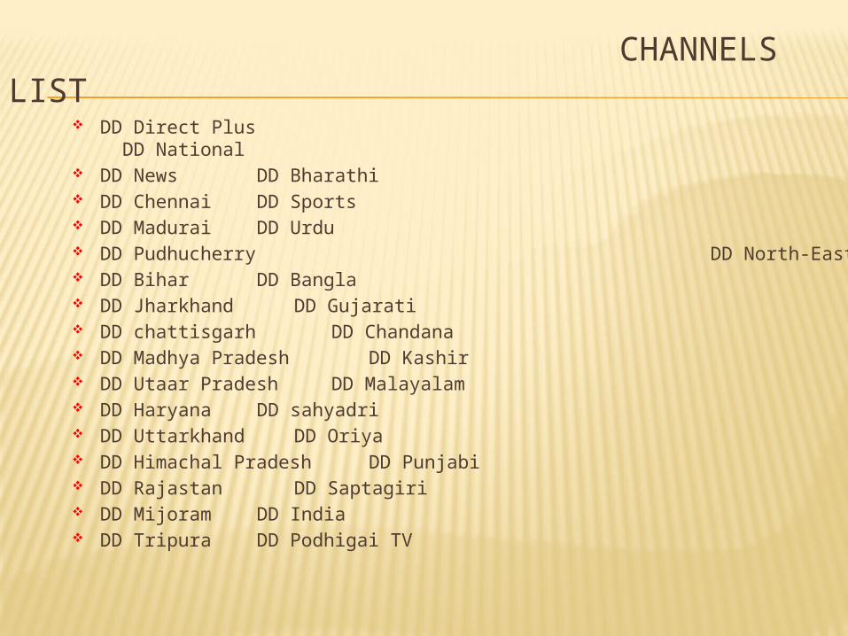
CHANNELS LIST
DD Direct Plus DD National DD News DD Bharathi DD Chennai DD Sports DD Madurai DD Urdu DD Pudhucherry DD North-East DD Bihar DD Bangla DD Jharkhand DD Gujarati DD chattisgarh DD Chandana DD Madhya Pradesh DD Kashir DD Utaar Pradesh DD Malayalam DD Haryana DD sahyadri DD Uttarkhand DD Oriya DD Himachal Pradesh DD Punjabi DD Rajastan DD Saptagiri DD Mijoram DD India DD Tripura DD Podhigai TV
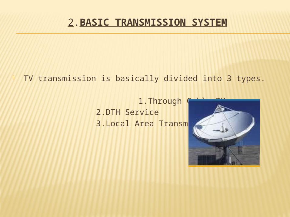
2.BASIC TRANSMISSION SYSTEM
TV transmission is basically divided into 3 types.
1.Through Cable TV
2.DTH Service
3.Local Area Transmission
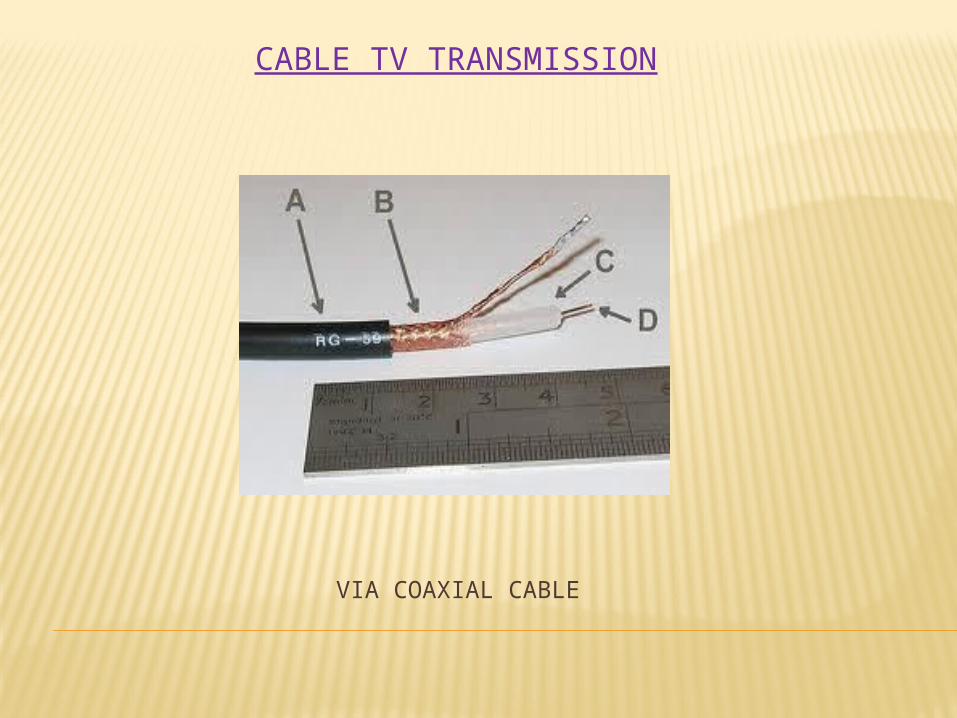
VIA COAXIAL CABLE
CABLE TV TRANSMISSION
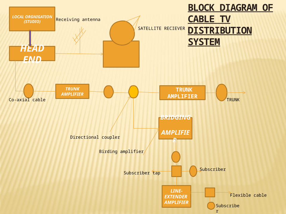
LOCAL ORGNIGATION
(STUDIO)
HEAD END
TRUNK AMPLIFIER
TRUNK AMPLIFIER
BRIDGING
AMPLIFIER
LINE-EXTENDE
R AMPLIFIE
R
SATELLITE RECIEVER
TRUNK
Receiving antenna
Co-axial cable
Directional coupler
Birding amplifier
Subscriber tapSubscriber
Subscriber
Flexible cable
BLOCK DIAGRAM OF CABLE TV DISTRIBUTION SYSTEM

8
DTH stands for DIRECT-TO-HOME television.
DTH is defined as:
The reception of satellite programmers with a
personal dish in an individual home.
DTH does away with the need for the local
cable operator and puts the broadcaster
directly in touch with consumer .
HISTORY
DTH was first invented by sir ARTHURE CHARLES CLARKE,a british inventor in late 1946.
DTH services were first proposed in INDIA in 1996. But was not approved due to the concerns over national security.
Finally, in 2000 DTH was allowed and it was Doordarshan which made it possible to provide its facilities to consumers from 1st April 2000.
Broadcasters like STAR and ZEE are pushing hard for DTH services in INDIA.
The operators were required to setup earth stations in INDIA within 12 month for getting license of broadcasting whose cost was $2.14 million and will be valid for 10 years.
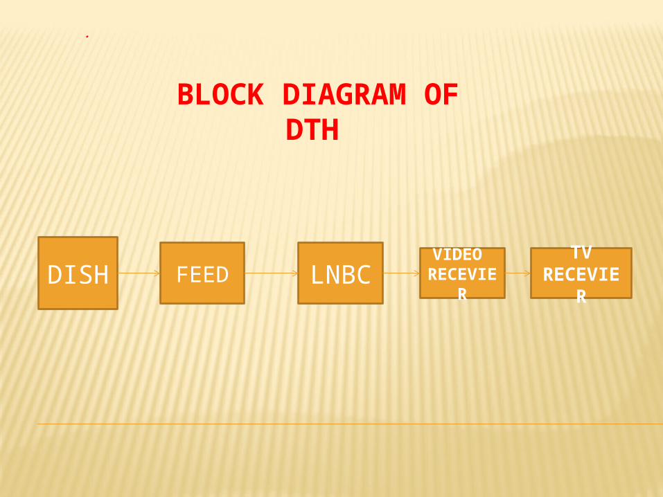
BLOCK DIAGRAM OF DTH
DISH FEED LNBCVIDEO RECEVI
ER
TVRECEVIE
R
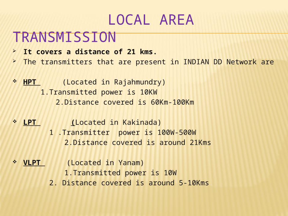
LOCAL AREA TRANSMISSION It covers a distance of 21 kms. The transmitters that are present in INDIAN DD Network are
HPT (Located in Rajahmundry)
1.Transmitted power is 10KW
2.Distance covered is 60Km-100Km
LPT (Located in Kakinada)
1 .Transmitter power is 100W-500W
2.Distance covered is around 21Kms
VLPT (Located in Yanam)
1.Transmitted power is 10W
2. Distance covered is around 5-10Kms
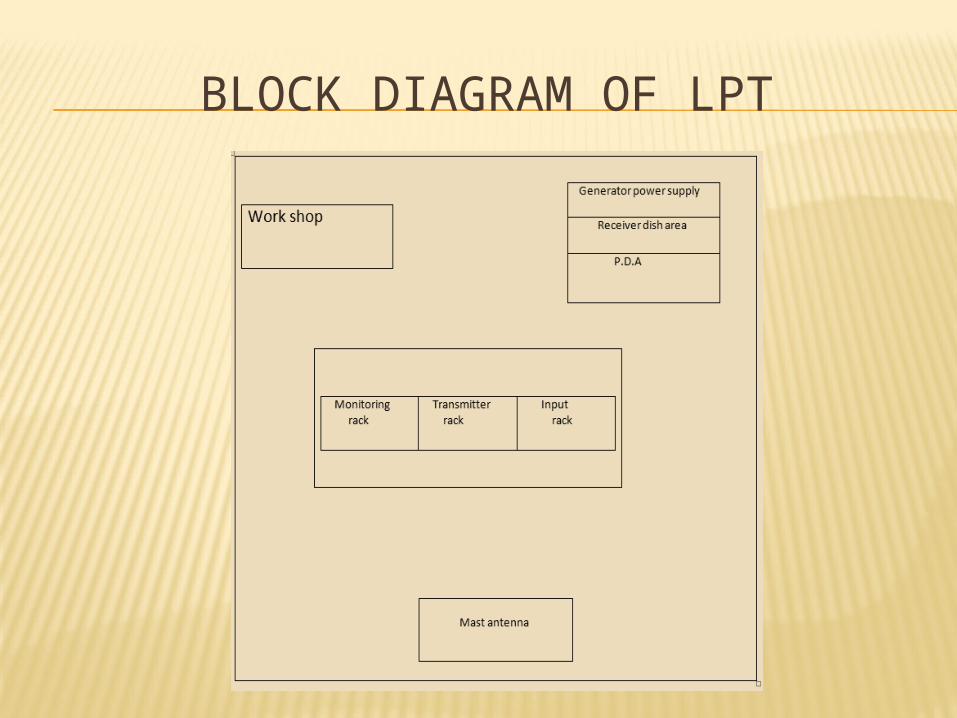
BLOCK DIAGRAM OF LPT
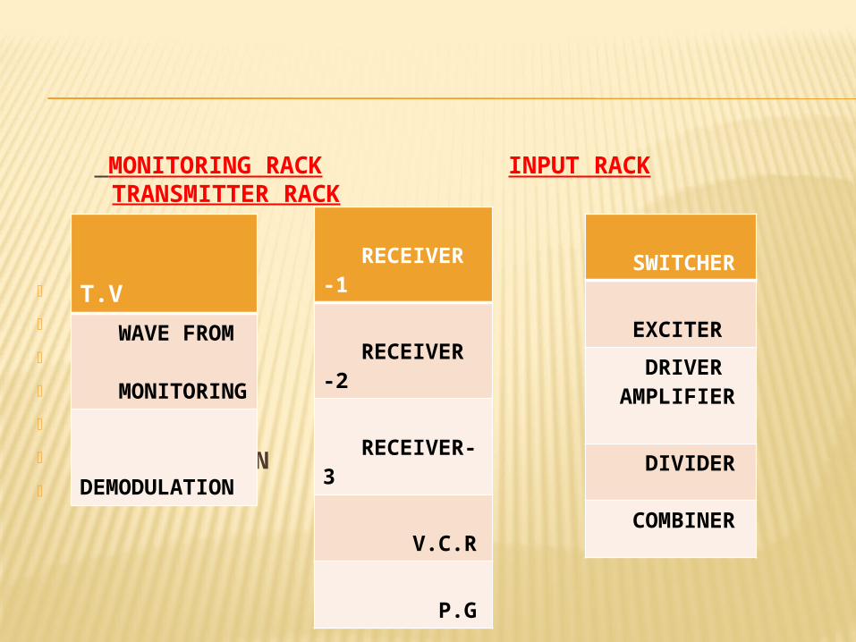
MONITORING RACK INPUT RACK TRANSMITTER RACK
T.V WAVE FROM MONITORING DEMODULATION
T.V
WAVE FROM MONITORING
DEMODULATION
RECEIVER -1
RECEIVER -2
RECEIVER-3
V.C.R
P.G
SWITCHER
EXCITER
DRIVER AMPLIFIER
DIVIDER
COMBINER
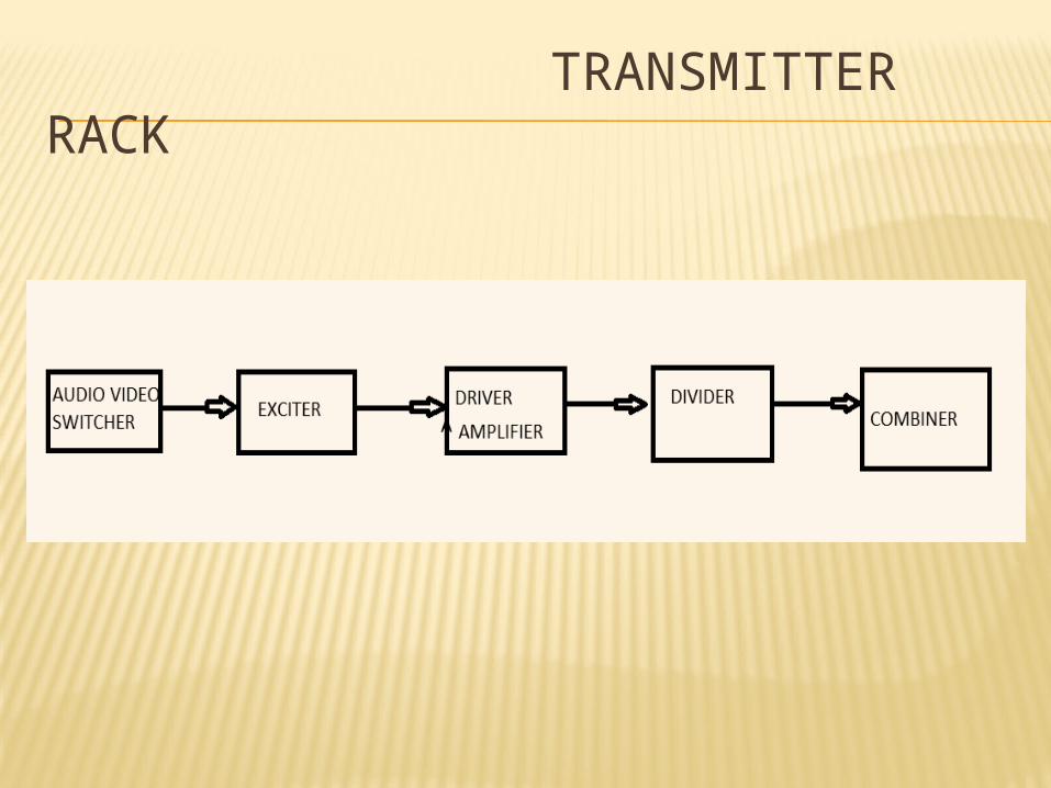
TRANSMITTER RACK
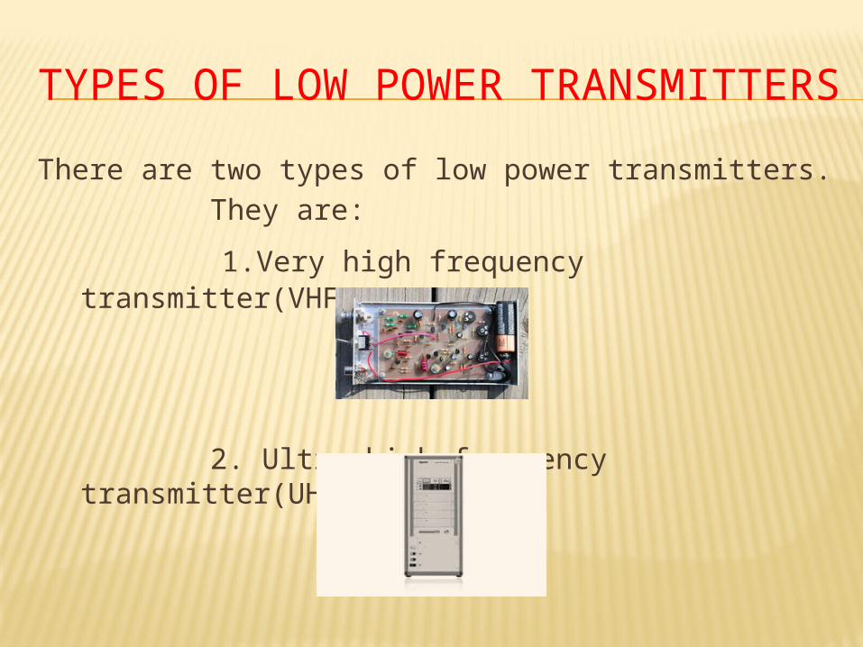
TYPES OF LOW POWER TRANSMITTERS
There are two types of low power transmitters.
They are:
1.Very high frequency transmitter(VHF)
2. Ultra high frequency transmitter(UHF)
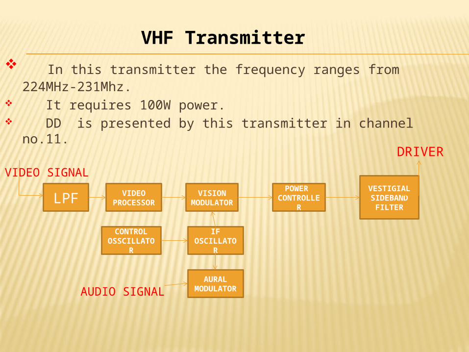
In this transmitter the frequency ranges from 224MHz-231Mhz. It requires 100W power. DD is presented by this transmitter in channel no.11.
VIDEO SIGNAL
LPFVIDEO
PROCESSOR
VISION MODULAT
OR
POWER CONTROL
LER
VESTIGIAL SIDEBAND
FILTER
IF OSCILLATO
R
AURAL MODULATO
R
CONTROL OSSCILLAT
OR
DRIVER
AUDIO SIGNAL
VHF Transmitter
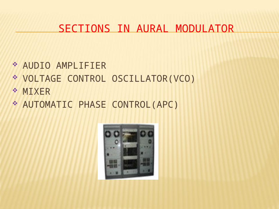
SECTIONS IN AURAL MODULATOR
AUDIO AMPLIFIER VOLTAGE CONTROL OSCILLATOR(VCO) MIXER AUTOMATIC PHASE CONTROL(APC)
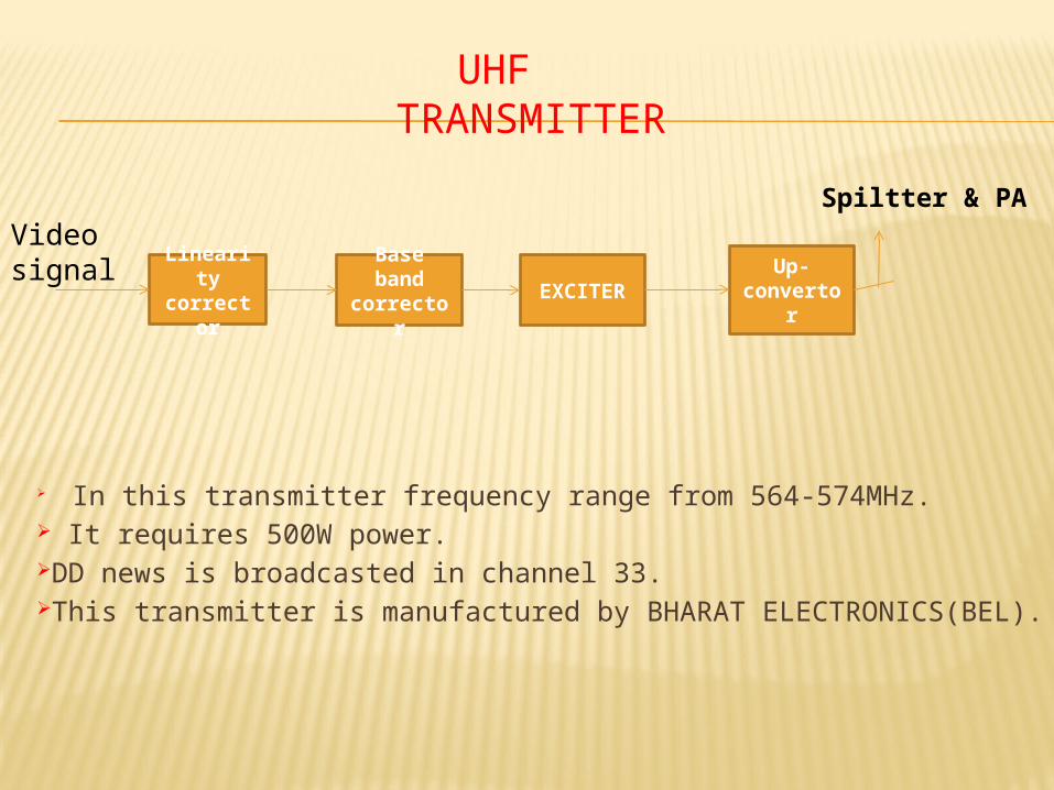
UHF TRANSMITTER
In this transmitter frequency range from 564-574MHz. It requires 500W power. DD news is broadcasted in channel 33. This transmitter is manufactured by BHARAT ELECTRONICS(BEL).
Linearity corrector
Base band corrector
EXCITERUp-
convertor
Video signal
Spiltter & PA
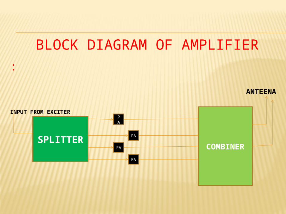
:
SPLITTER
PA
PA
PA
PA
COMBINER
INPUT FROM EXCITER
ANTEENA
BLOCK DIAGRAM OF AMPLIFIER
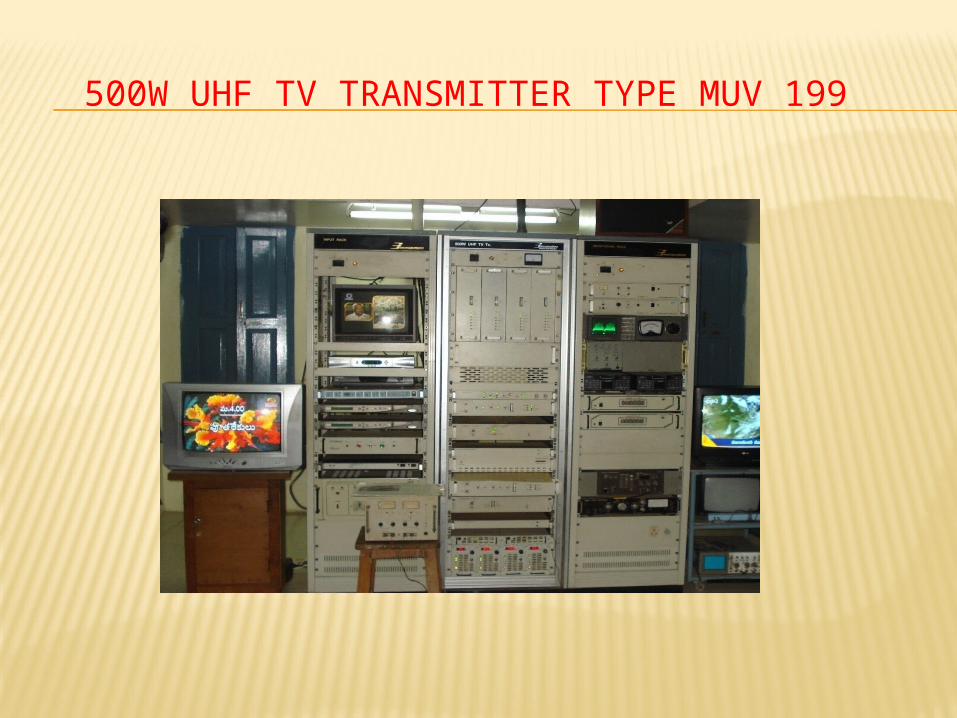
500W UHF TV TRANSMITTER TYPE MUV 199
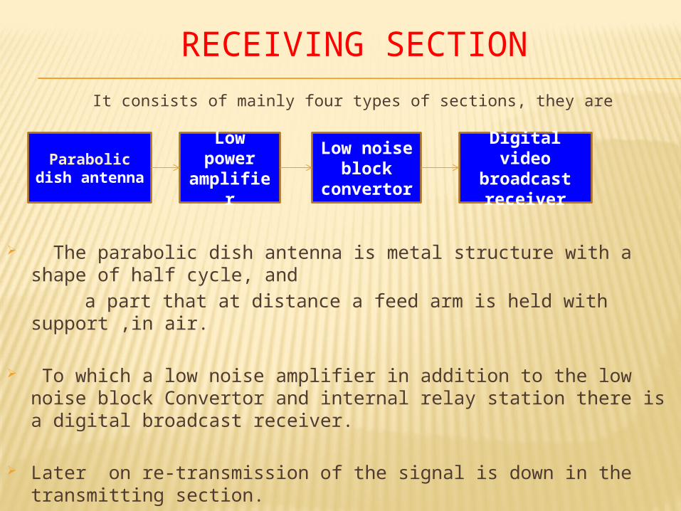
RECEIVING SECTION
It consists of mainly four types of sections, they are
The parabolic dish antenna is metal structure with a shape of half cycle, and
a part that at distance a feed arm is held with support ,in air.
To which a low noise amplifier in addition to the low noise block Convertor and internal relay station there is a digital broadcast receiver.
Later on re-transmission of the signal is down in the transmitting section.
Parabolic dish
antenna
Low power
amplifier
Low noise block
convertor
Digital video
broadcast receiver
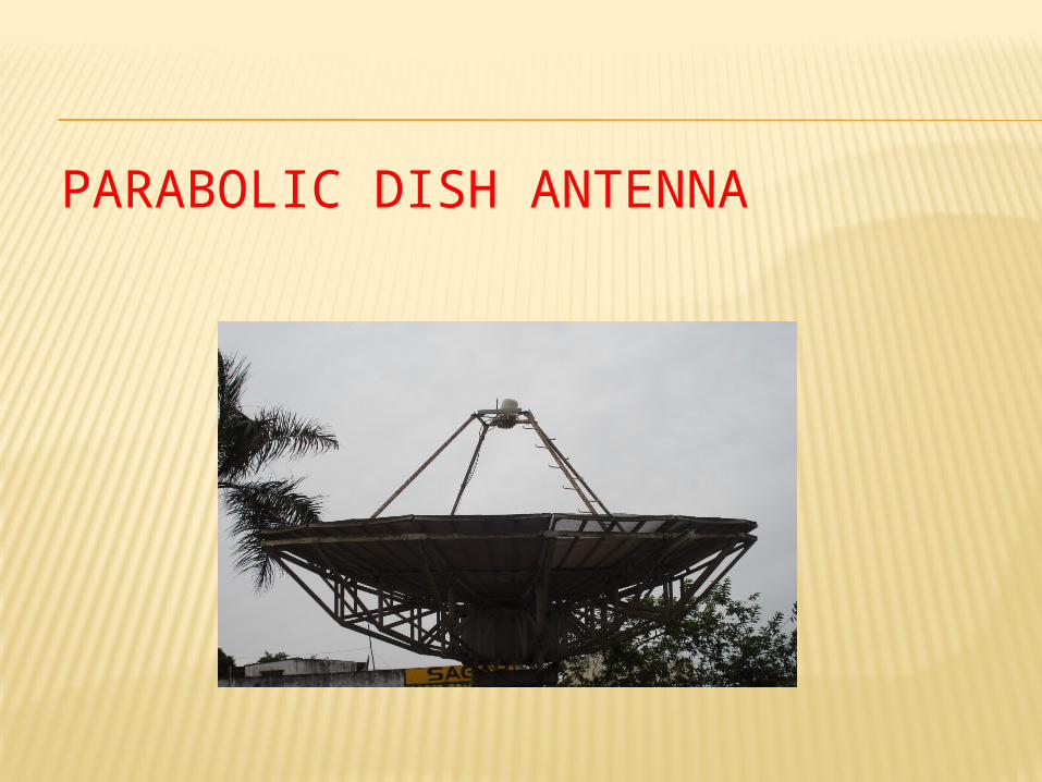
PARABOLIC DISH ANTENNA
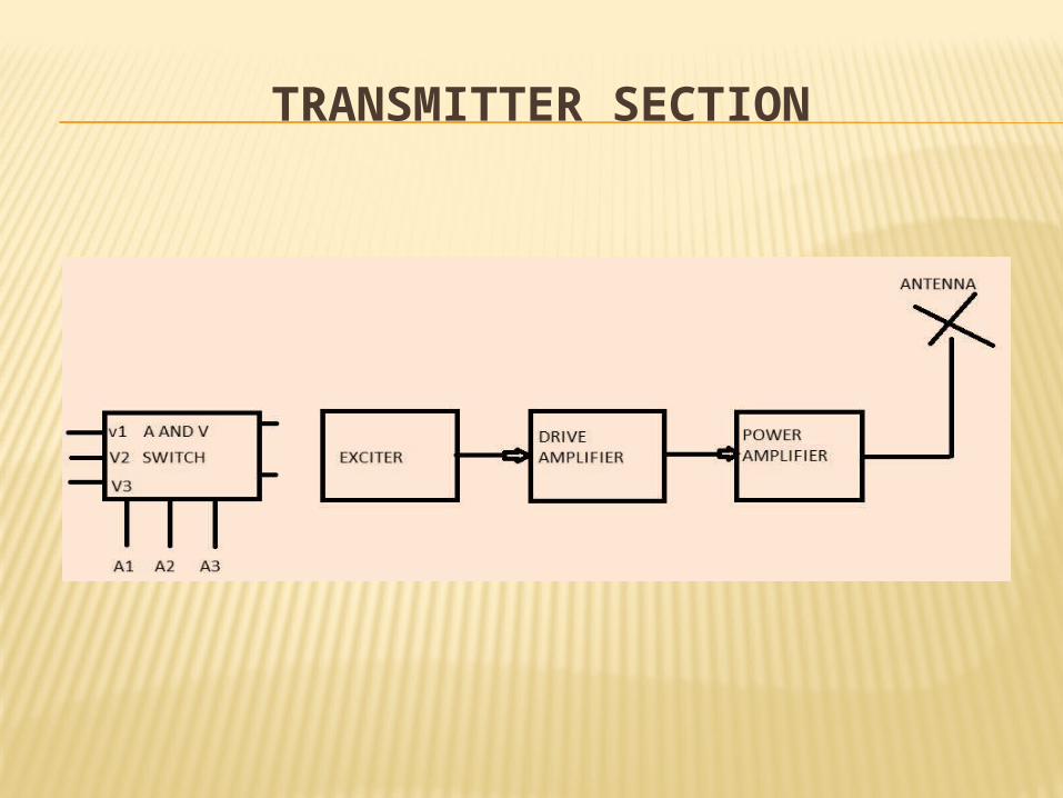
TRANSMITTER SECTION
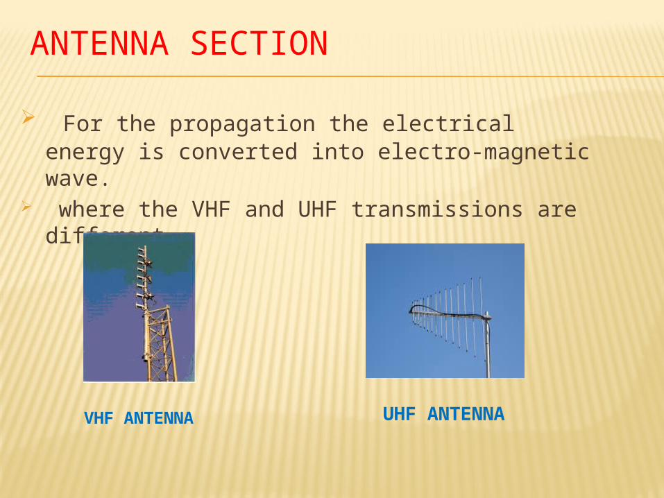
ANTENNA SECTION
For the propagation the electrical energy is converted into electro-magnetic wave.
where the VHF and UHF transmissions are different.
VHF ANTENNA UHF ANTENNA
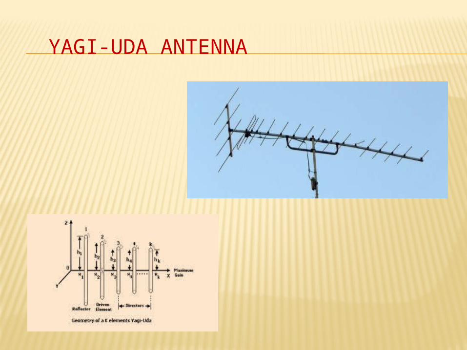
YAGI-UDA ANTENNA
DIFFERENT TYPES OF PROPAGATION
1.Sky wave propagation [2 to 30KHz]: This is used for long radio communication at medium and high frequencies This is used to long distance, point to point communication is possible.
2.Space wave propagation[>30MHz]: Height of the this is 16KMs from atmosphere is known as troposphere.
3.Ground wave propagation: As two antennas are with in the line of sight of each propagation of such space
wave is called line of propagation.
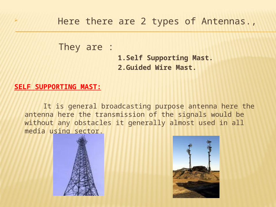
Here there are 2 types of Antennas.,
They are : 1.Self Supporting Mast.
2.Guided Wire Mast.
SELF SUPPORTING MAST:
It is general broadcasting purpose antenna here the antenna here the transmission of the signals would be without any obstacles it generally almost used in all media using sector.
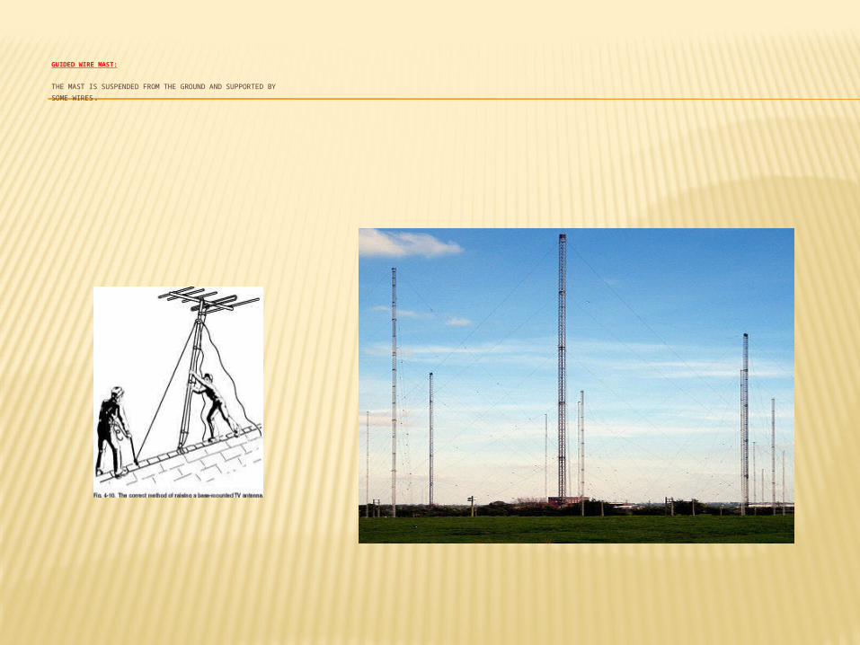
GUIDED WIRE MAST:
THE MAST IS SUSPENDED FROM THE GROUND AND SUPPORTED BY
SOME WIRES.

conclusi
on