manual - byk additives & instruments · corner is the tool icon to get to the setup screen. the...
TRANSCRIPT
Additives & InstrumentsA member of
Measure what you see.
Gardner-scrubAbrasion Tester
Manual

En
glis
h
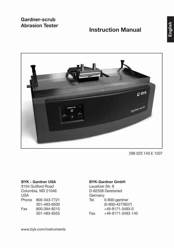
Gardner-scrub Abrasion Tester
Instruction Manual
BYK-Gardner GmbHLausitzer Str. 8D-82538 GeretsriedGermanyTel. 0-800-gardner (0-800-4273637) +49-8171-3493-0Fax +49-8171-3493-140
BYK - Gardner USA9104 Guilford RoadColumbia, MD 21046USAPhone 800-343-7721 301-483-6500Fax 800-394-8215 301-483-6555
www.byk.com/instruments
298 023 140 E 1507
4
Dear customer,thank you for having decided for a BYK-Gardner product. BYK-Gardner is committed to providing you with quality products and services. We offer complete system solutions to solve your problems in areas of color, appearance and physical properties. As the basis of our worldwide business, we strongly believe in total customer satisfaction. Therefore, in addition to our products, we offer many VALUE-ADDED services:- Technical Sales Force- Technical & Application Support- Application and Technical Seminars- Repair & Certification Service
BYK-Gardner is part of the Additives and Instrument Division of ALTANA AG, a leading supplier of additives for coatings and plastics. Together, we offer complete and unique solutions for you, our customer.
Thank you for your trust and confidence. If there isanything we can do better to serve your needs, donot hesitate to let us know.
Your BYK-Gardner Team
5
Table of Content06 Safety Instructions
08 Preparation – Setup
10 System Description
12 Start-up
15 Operation
17 Maintenance and Repair
18 Technical Specifications
20 Appendix A – ASTM D 2486 setup
22 Appendix B – ISO 11998 setup
23 Appendix C – DIN 53778 setup
6
Safety InformationCaution!Read Instruction Manual before using this instrument.
Warning! This manual cannot address all of the safety considerations associated with its use. It is the responsibility of the user to consult this manual and establish appropriate safety practices for use with this equipment and the individual material being tested.
Warning! The Gardner-scrub Abrasion Tester is designed and intended for the use described in this manual. Using the Abrasion Tester for other purposes for which it was not designed may reduce or eliminate the protection offered by the features of the applicator. Serious injury may result.
Warning! Never defeat the ground conductor or operate the equipment in the absence of a suitably installed ground conductor. Contact the appropriate electrical inspection authority or an electrician if you are uncertain that suitable grounding is available.
Warning! Ultimate disposal of this product should be handled according to all national laws and regulations.
Safety Information
7
Safety Information
AttentionThe Gardner-scrub Abrasion Tester works with a moving traverse carriage. No parts of the carriage may be touched or held during operation. Once the Run button is pressed no work should be carried out within the travel area of the carriage.
Please note the following points:• During testing operation the carriage oscillates
across the top surface of the instrument.
• Familiarize yourself with the layout and operation of the controls.
• Pressing anywhere on the screen while the instrument is running will immediately stop the carriage at any point of its travel.
• Ensure the operator has no loose clothing or jewelry which could become caught in the moving parts.
8
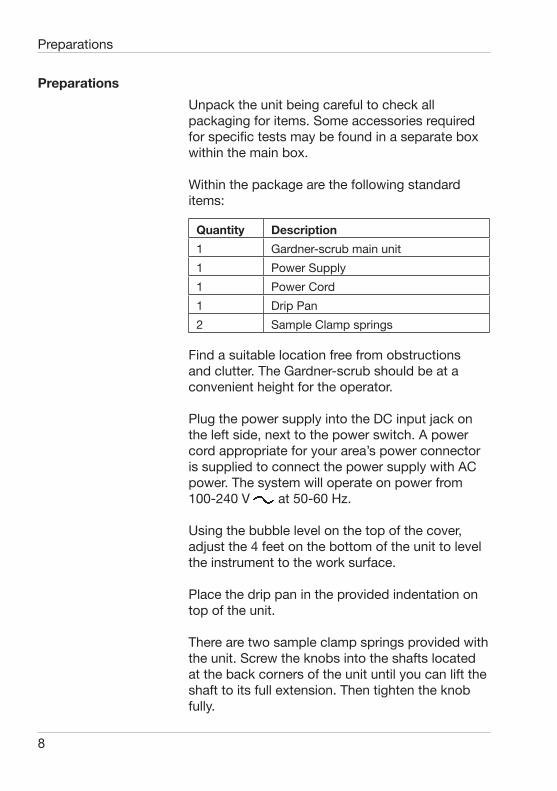
PreparationsUnpack the unit being careful to check all packaging for items. Some accessories required for specific tests may be found in a separate box within the main box.
Within the package are the following standard items:
Quantity Description1 Gardner-scrub main unit1 Power Supply1 Power Cord1 Drip Pan2 Sample Clamp springs
Find a suitable location free from obstructions and clutter. The Gardner-scrub should be at a convenient height for the operator.
Plug the power supply into the DC input jack on the left side, next to the power switch. A power cord appropriate for your area’s power connector is supplied to connect the power supply with AC power. The system will operate on power from 100-240 V at 50-60 Hz.
Using the bubble level on the top of the cover, adjust the 4 feet on the bottom of the unit to level the instrument to the work surface.
Place the drip pan in the provided indentation on top of the unit.
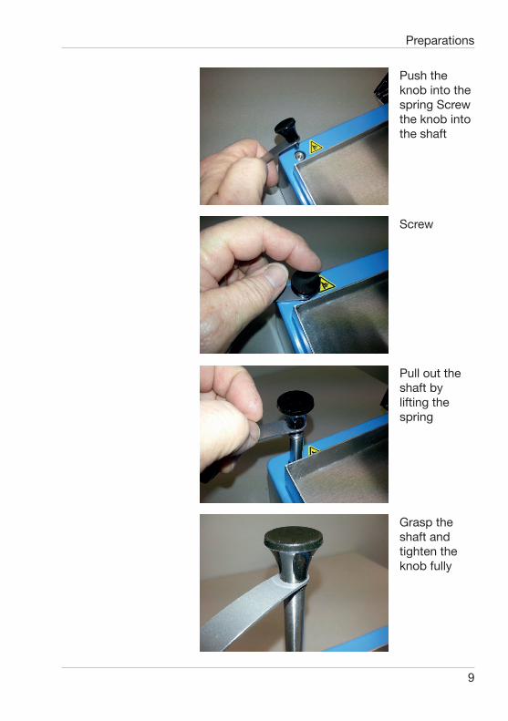
There are two sample clamp springs provided with the unit. Screw the knobs into the shafts located at the back corners of the unit until you can lift the shaft to its full extension. Then tighten the knob fully.
Preparations
9
Preparations
Push the knob into the spring Screw the knob into the shaft
Screw
Pull out the shaft by lifting the spring
Grasp the shaft and tighten the knob fully
10
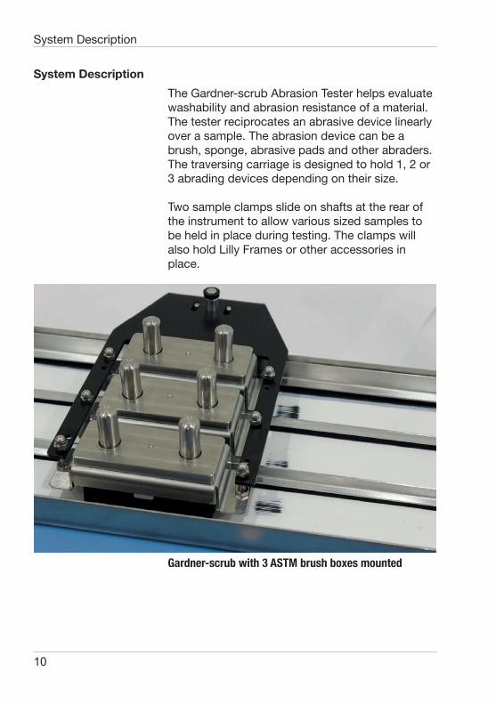
System DescriptionThe Gardner-scrub Abrasion Tester helps evaluate washability and abrasion resistance of a material. The tester reciprocates an abrasive device linearly over a sample. The abrasion device can be a brush, sponge, abrasive pads and other abraders. The traversing carriage is designed to hold 1, 2 or 3 abrading devices depending on their size.
Two sample clamps slide on shafts at the rear of the instrument to allow various sized samples to be held in place during testing. The clamps will also hold Lilly Frames or other accessories in place.
Gardner-scrub with 3 ASTM brush boxes mounted
System Description
11
System Description
The Gardner-scrub incorporates a precise speed control to maintain a constant speed for the test. The instrument is preset at 37 strokes per minute to coincide with most standardized tests, but may be adjusted within the range of 6 to 60 strokes per minute. Unlike some other instruments on the market, the Gardner-scrub maintains a linear speed over its travel length. The result is a more consistent and repeatable test.
A front mounted, color touch screen is provided for user interaction. All adjustments are available in the setup screen to provide a flexible interaction with the user.
The instrument is setup at the factory for a center-to-center stroke length of 10 inches. Stroke lengths of 9 or 11 inches may be achieved by means of a mechanical adjustment. This adjustment must be performed by the factory or an authorized service center.
12
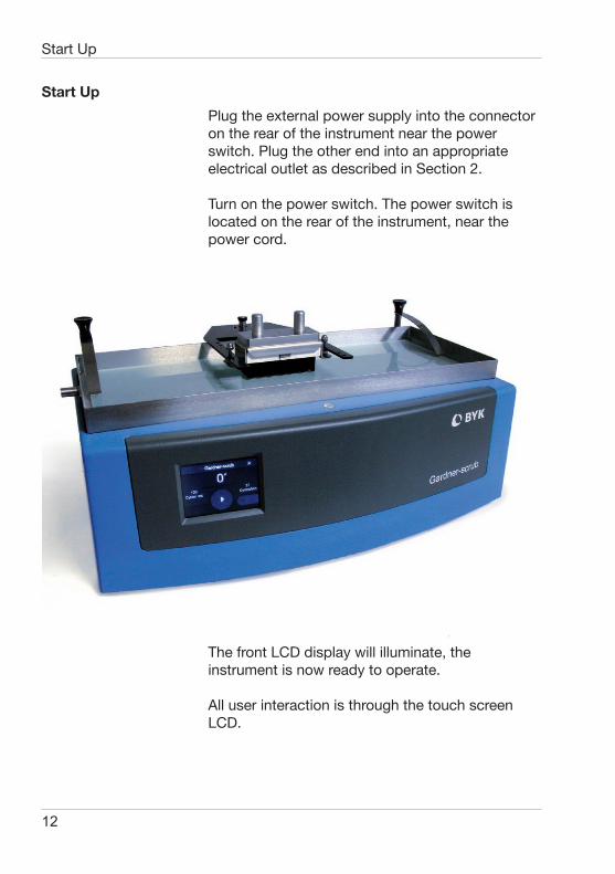
Start UpPlug the external power supply into the connector on the rear of the instrument near the power switch. Plug the other end into an appropriate electrical outlet as described in Section 2.
Turn on the power switch. The power switch is located on the rear of the instrument, near the power cord.
The front LCD display will illuminate, the instrument is now ready to operate.
All user interaction is through the touch screen LCD.
Start Up
13
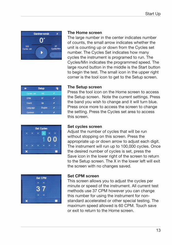
The Home screenThe large number in the center indicates number of counts, the small arrow indicates whether the unit is counting up or down from the Cycles set number. The Cycles Set indicates how many cycles the instrument is programed to run. The Cycles/Min indicates the programmed speed. The large round button in the middle is the Start button to begin the test. The small icon in the upper right corner is the tool icon to get to the Setup screen.
The Setup screenPress the tool icon on the Home screen to access the Setup screen. Note the current settings. Press the band you wish to change and it will turn blue. Press once more to access the screen to change the setting. Press the Cycles set area to access this screen.
Set cycles screenAdjust the number of cycles that will be run without stopping on this screen. Press the appropriate up or down arrow to adjust each digit. The instrument will run up to 100,000 cycles. Once the desired number of cycles is set, press the Save icon in the lower right of the screen to return to the Setup screen. The X in the lower left will exit the screen with no changes saved.
Set CPM screenThis screen allows you to adjust the cycles per minute or speed of the instrument. All current test methods use 37 CPM however you can change this number for using the instrument for non-standard accelerated or other special testing. The maximum speed allowed is 60 CPM. Touch save or exit to return to the Home screen.
Start Up
14
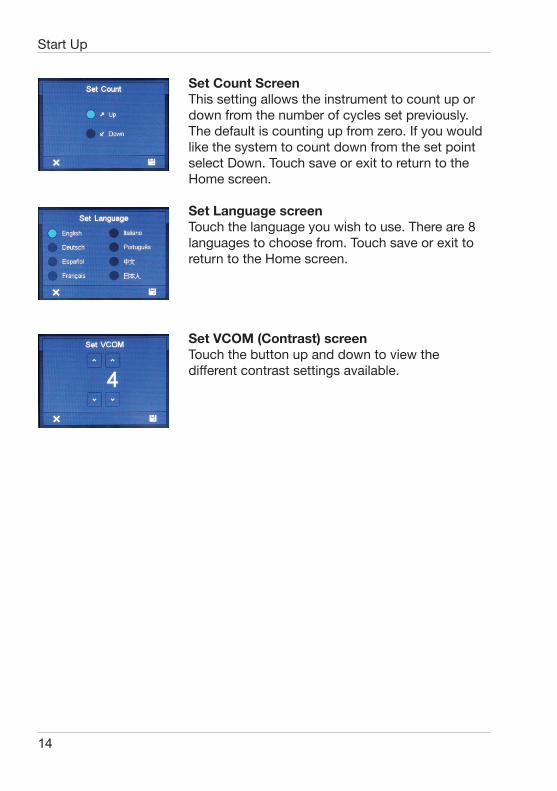
Set Count ScreenThis setting allows the instrument to count up or down from the number of cycles set previously. The default is counting up from zero. If you would like the system to count down from the set point select Down. Touch save or exit to return to the Home screen.
Set Language screenTouch the language you wish to use. There are 8 languages to choose from. Touch save or exit to return to the Home screen.
Set VCOM (Contrast) screenTouch the button up and down to view the different contrast settings available.
Start Up
15
Operation
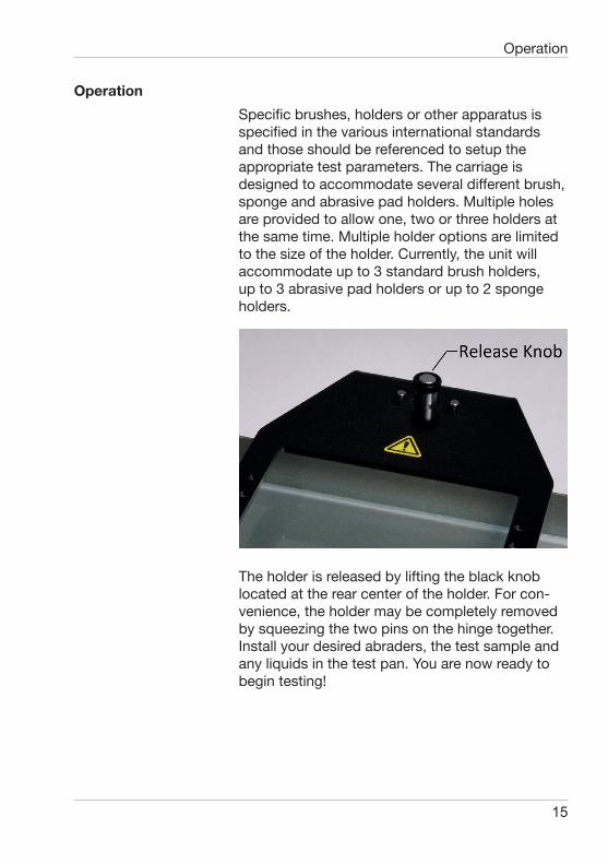
OperationSpecific brushes, holders or other apparatus is specified in the various international standards and those should be referenced to setup the appropriate test parameters. The carriage is designed to accommodate several different brush, sponge and abrasive pad holders. Multiple holes are provided to allow one, two or three holders at the same time. Multiple holder options are limited to the size of the holder. Currently, the unit will accommodate up to 3 standard brush holders, up to 3 abrasive pad holders or up to 2 sponge holders.
The holder is released by lifting the black knob located at the rear center of the holder. For con-venience, the holder may be completely removed by squeezing the two pins on the hinge together. Install your desired abraders, the test sample and any liquids in the test pan. You are now ready to begin testing!

16
Home screen press the large Start button to testing. Once you press this button the screen will change to the Run Screen.
From the begin will change
When the Start button is pressed, the screen changes to Run mode. The Start button turns blue and is now a Pause button. The Stop button is now active and is indicated by the red square. The Progress bar is in blue to help indicate how far along the test has run. To pause operation without resetting the counter, press the large blue Pause button. To stop operation and reset the counter, press the red square area Stop button.
When the pause button is pressed (or anywhere except the Stop button area) This Pause screen will appear. To resume the test just press the yellow Run button. In our example the counter is stopped at 20 cycles on its way to a total of 100 cycles. Note the progress bar is also yellow. Pressing the Start button will continue from where the test was stopped. Pressing the Stop button will stop the test and reset the counter.As a safety measure, the instrument will stop and be placed in Pause mode if the screen is touched anywhere except the Stop button area. This is an Emergency Stop feature. As described above, the count will reset and the system will stop if the Stop button is pressed.
Pressing the Stop button also erases the current number of counts and resets the counter to zero (in count up mode) or to cycles set (in count down mode). A confirmation screen asks to confirm the Stop and reset operation.
Operation
17
Maintenance and Repair
Maintenance and RepairCleaning and Routine MaintenanceCare should be taken to avoid letting abrasion materials spill from the pan. If spillage occurs, clean the covers with mild soap and water as soon as practical. If abrasive substances are spilled on the LCD display clean it with mild soap and water. This includes a glass surface so take care not to use excessive force. Avoid solvents on the cover and the LCD as they may be seriously damaged by strong solvents.
TroubleshootingIf the carriage becomes jammed the instrument will stop and report an error message. If this occurs, turn off the power, remove the power connector from the rear of the unit and clear any visible jams. Once cleared, replace the power connector and turn on the instrument. If a jam is still indicated, contact your local BYK-Gardner office for assistance.
Service and Spare PartsFor all service and spare parts requirements, please contact your local BYK-Gardner office.
Components
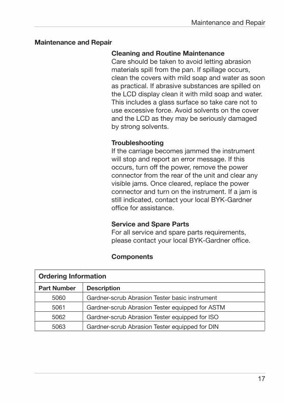
Ordering InformationPart Number Description
5060 Gardner-scrub Abrasion Tester basic instrument5061 Gardner-scrub Abrasion Tester equipped for ASTM5062 Gardner-scrub Abrasion Tester equipped for ISO5063 Gardner-scrub Abrasion Tester equipped for DIN
18
Maintenance and Repair
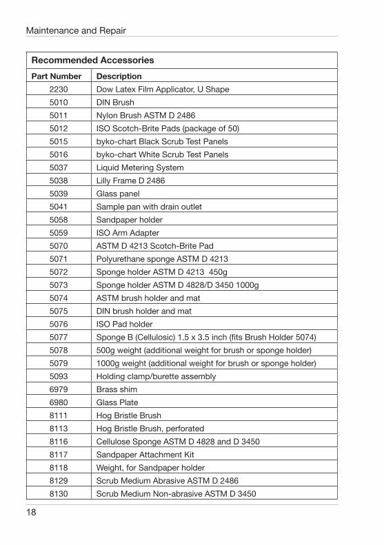
Recommended AccessoriesPart Number Description
2230 Dow Latex Film Applicator, U Shape5010 DIN Brush5011 Nylon Brush ASTM D 24865012 ISO Scotch-Brite Pads (package of 50)5015 byko-chart Black Scrub Test Panels5016 byko-chart White Scrub Test Panels5037 Liquid Metering System5038 Lilly Frame D 24865039 Glass panel5041 Sample pan with drain outlet5058 Sandpaper holder 5059 ISO Arm Adapter5070 ASTM D 4213 Scotch-Brite Pad5071 Polyurethane sponge ASTM D 42135072 Sponge holder ASTM D 4213 450g5073 Sponge holder ASTM D 4828/D 3450 1000g5074 ASTM brush holder and mat5075 DIN brush holder and mat 5076 ISO Pad holder5077 Sponge B (Cellulosic) 1.5 x 3.5 inch (fits Brush Holder 5074)5078 500g weight (additional weight for brush or sponge holder)5079 1000g weight (additional weight for brush or sponge holder)5093 Holding clamp/burette assembly6979 Brass shim6980 Glass Plate8111 Hog Bristle Brush8113 Hog Bristle Brush, perforated8116 Cellulose Sponge ASTM D 4828 and D 34508117 Sandpaper Attachment Kit8118 Weight, for Sandpaper holder8129 Scrub Medium Abrasive ASTM D 24868130 Scrub Medium Non-abrasive ASTM D 3450
19
Technical Specifications
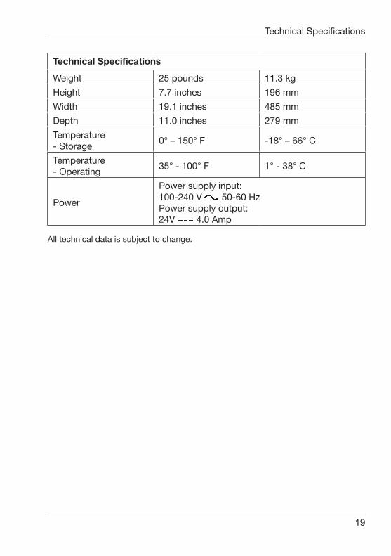
Technical Specifications
Weight 25 pounds 11.3 kgHeight 7.7 inches 196 mmWidth 19.1 inches 485 mmDepth 11.0 inches 279 mmTemperature- Storage 0° – 150° F -18° – 66° C
Temperature- Operating 35° - 100° F 1° - 38° C
Power
Power supply input: 100-240 V 50-60 HzPower supply output: 24V 4.0 Amp
All technical data is subject to change.
20
Appendix A – ASTM Test Setup – Part Number 5064The ASTM brush and holder is easy to install and quite versatile. This guide is intended to help the user set up the Gardner-scrub for use with the ASTM standards. Please refer to specific standard for a complete description of the test method.
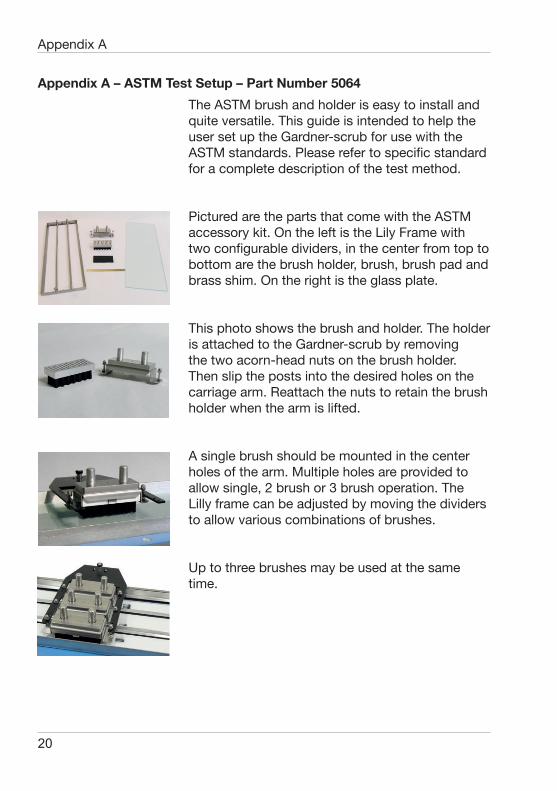
Pictured are the parts that come with the ASTM accessory kit. On the left is the Lily Frame with two configurable dividers, in the center from top to bottom are the brush holder, brush, brush pad and brass shim. On the right is the glass plate.
This photo shows the brush and holder. The holder is attached to the Gardner-scrub by removing the two acorn-head nuts on the brush holder. Then slip the posts into the desired holes on the carriage arm. Reattach the nuts to retain the brush holder when the arm is lifted.
A single brush should be mounted in the center holes of the arm. Multiple holes are provided to allow single, 2 brush or 3 brush operation. The Lilly frame can be adjusted by moving the dividers to allow various combinations of brushes.
Up to three brushes may be used at the same time.
Appendix A
21
Appendix A
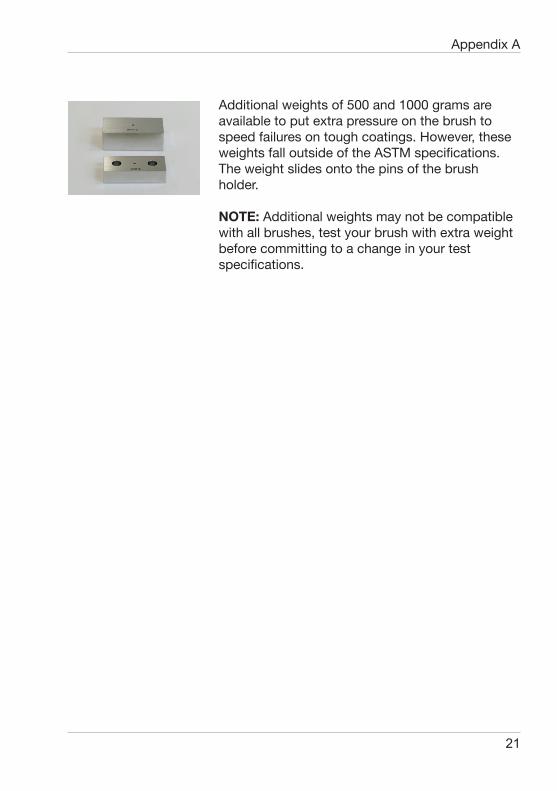
Additional weights of 500 and 1000 grams are available to put extra pressure on the brush to speed failures on tough coatings. However, these weights fall outside of the ASTM specifications. The weight slides onto the pins of the brush holder.
NOTE: Additional weights may not be compatible with all brushes, test your brush with extra weight before committing to a change in your test specifications.
22
Appendix B – ISO Test Setup – Part Number 5065The ISO accessory kit includes an adapter and pad holder for using abrasive pads with the Gardner-scrub. This guide is intended to help the user set up the Gardner-scrub for use with the ISO standards. Please refer to specific standard for a complete description of the test method.
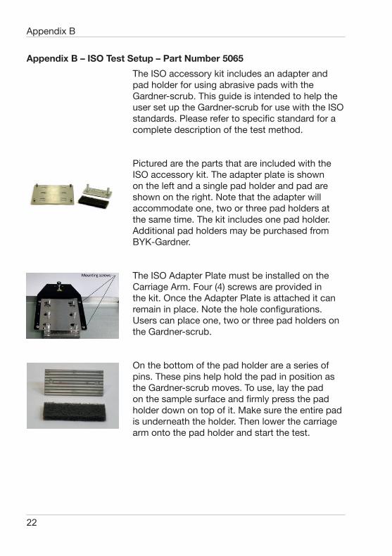
Pictured are the parts that are included with the ISO accessory kit. The adapter plate is shown on the left and a single pad holder and pad are shown on the right. Note that the adapter will accommodate one, two or three pad holders at the same time. The kit includes one pad holder. Additional pad holders may be purchased from BYK-Gardner.
The ISO Adapter Plate must be installed on the Carriage Arm. Four (4) screws are provided in the kit. Once the Adapter Plate is attached it can remain in place. Note the hole configurations. Users can place one, two or three pad holders on the Gardner-scrub.
On the bottom of the pad holder are a series of pins. These pins help hold the pad in position as the Gardner-scrub moves. To use, lay the pad on the sample surface and firmly press the pad holder down on top of it. Make sure the entire pad is underneath the holder. Then lower the carriage arm onto the pad holder and start the test.
Appendix B
23
Appendix C
Appendix C – DIN Test Setup – Part Number 5066The DIN accessory kit includes all of the additional parts needed to use the Gardner-scrub for DIN 53778. This guide is intended to help the user set up the Gardner-scrub for use with this DIN method. Please refer to specific standard for a complete description of the test method.
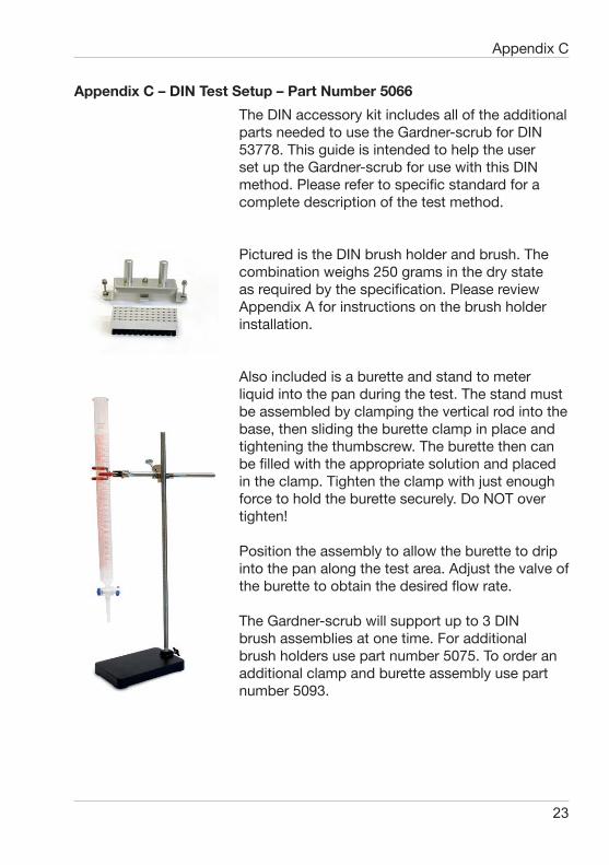
Pictured is the DIN brush holder and brush. The combination weighs 250 grams in the dry state as required by the specification. Please review Appendix A for instructions on the brush holder installation.
Also included is a burette and stand to meter liquid into the pan during the test. The stand must be assembled by clamping the vertical rod into the base, then sliding the burette clamp in place and tightening the thumbscrew. The burette then can be filled with the appropriate solution and placed in the clamp. Tighten the clamp with just enough force to hold the burette securely. Do NOT over tighten!
Position the assembly to allow the burette to drip into the pan along the test area. Adjust the valve of the burette to obtain the desired flow rate.
The Gardner-scrub will support up to 3 DIN brush assemblies at one time. For additional brush holders use part number 5075. To order an additional clamp and burette assembly use part number 5093.

298 023 140 E 1507