marcstar i e/d remote control encoder/decoders
TRANSCRIPT
TRC1300, TRC1315MARCSTAR I E/D
REMOTE CONTROL ENCODER/DECODERS
SLWS011D – AUGUST 1996 – REVISED JANUARY 1997
1POST OFFICE BOX 655303 • DALLAS, TEXAS 75265
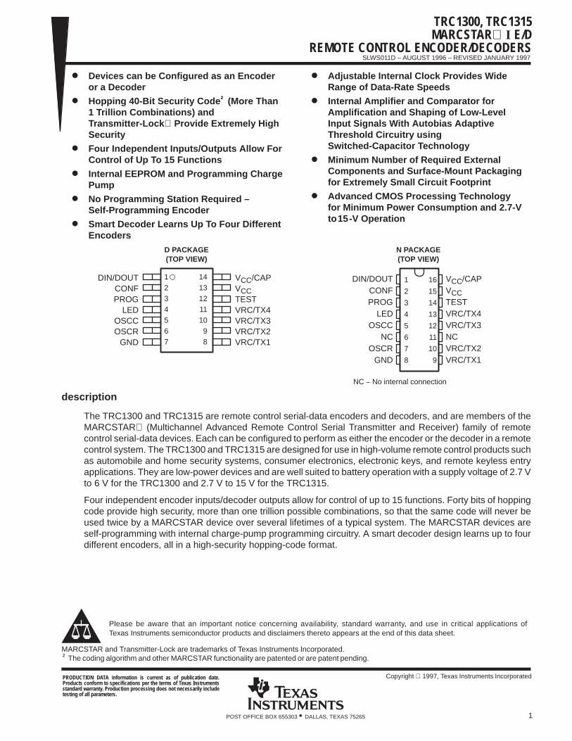
Devices can be Configured as an Encoderor a Decoder
Hopping 40-Bit Security Code † (More Than 1 Trillion Combinations) andTransmitter-Lock Provide Extremely HighSecurity
Four Independent Inputs/Outputs Allow ForControl of Up To 15 Functions
Internal EEPROM and Programming ChargePump
No Programming Station Required –Self-Programming Encoder
Smart Decoder Learns Up To Four DifferentEncoders
Adjustable Internal Clock Provides WideRange of Data-Rate Speeds
Internal Amplifier and Comparator forAmplification and Shaping of Low-LevelInput Signals With Autobias AdaptiveThreshold Circuitry usingSwitched-Capacitor Technology
Minimum Number of Required ExternalComponents and Surface-Mount Packagingfor Extremely Small Circuit Footprint
Advanced CMOS Processing Technologyfor Minimum Power Consumption and 2.7-Vto15-V Operation
NC – No internal connection
1
2
3
4
5
6
7
8
16
15
14
13
12
11
10
9
DIN/DOUTCONFPROG
LEDOSCC
NCOSCR
GND
VCC/CAPVCCTESTVRC/TX4VRC/TX3NCVRC/TX2VRC/TX1
1
2
3
4
5
6
7
14
13
12
11
10
9
8
DIN/DOUTCONFPROG
LEDOSCCOSCR
GND
VCC/CAPVCCTESTVRC/TX4VRC/TX3VRC/TX2VRC/TX1
D PACKAGE(TOP VIEW)
N PACKAGE(TOP VIEW)
description
The TRC1300 and TRC1315 are remote control serial-data encoders and decoders, and are members of theMARCSTAR (Multichannel Advanced Remote Control Serial Transmitter and Receiver) family of remotecontrol serial-data devices. Each can be configured to perform as either the encoder or the decoder in a remotecontrol system. The TRC1300 and TRC1315 are designed for use in high-volume remote control products suchas automobile and home security systems, consumer electronics, electronic keys, and remote keyless entryapplications. They are low-power devices and are well suited to battery operation with a supply voltage of 2.7 Vto 6 V for the TRC1300 and 2.7 V to 15 V for the TRC1315.
Four independent encoder inputs/decoder outputs allow for control of up to 15 functions. Forty bits of hoppingcode provide high security, more than one trillion possible combinations, so that the same code will never beused twice by a MARCSTAR device over several lifetimes of a typical system. The MARCSTAR devices areself-programming with internal charge-pump programming circuitry. A smart decoder design learns up to fourdifferent encoders, all in a high-security hopping-code format.
Please be aware that an important notice concerning availability, standard warranty, and use in critical applications ofTexas Instruments semiconductor products and disclaimers thereto appears at the end of this data sheet.
MARCSTAR and Transmitter-Lock are trademarks of Texas Instruments Incorporated.† The coding algorithm and other MARCSTAR functionality are patented or are patent pending.
Copyright 1997, Texas Instruments IncorporatedPRODUCTION DATA information is current as of publication date.Products conform to specifications per the terms of Texas Instrumentsstandard warranty. Production processing does not necessarily includetesting of all parameters.

TRC1300, TRC1315MARCSTAR I E/DREMOTE CONTROL ENCODER/DECODERS
SLWS011D – AUGUST 1996 – REVISED JANUARY 1997
2 POST OFFICE BOX 655303 • DALLAS, TEXAS 75265
description (continued)
The TRC1300 and TRC1315 include several on-chip functions that normally require additional circuitry in asystem design. These include an amplifier/comparator for detection and shaping of input signals as low as afew millivolts (typically when an RF link is used) and a variable-frequency internal oscillator to clock thetransmitted or received security code.
The TRC1300 and TRC1315 MARCSTAR I E/D remote control encoder/decoders are characterized foroperation over the temperature range of –40°C to 85°C and are available in 14-pin SOIC small-outline ICsurface-mount (D) and 16-pin PDIP plastic dual in-line (N) packages.
functional block diagram
Encoder Logic
Input BufferAmplifier/Comparator
Clock/Oscillator
ShiftRegister
DecoderLogic
EEPROM Memory Cells(192 bits)
4 Banks of 40 Security Bitsand 8 Check-Sum Bits
ProgrammingLogic
(with charge pump)
DIN/DOUT 1
2CONF
LED 4
OSCC OSCR
7
GND
VRC/TX1
VRC/TX2
VRC/TX3
VRC/TX4
PROG
5 6
8
9
10
11
3
ConfigurationLogic
Voltage Regulator(TRC1315 Only)
VCC VCC/CAP13 14
NOTE A: Terminal numbers are for the D package.
12TEST
Mux
Mux
TRC1300, TRC1315MARCSTAR I E/D
REMOTE CONTROL ENCODER/DECODERS
SLWS011D – AUGUST 1996 – REVISED JANUARY 1997
3POST OFFICE BOX 655303 • DALLAS, TEXAS 75265
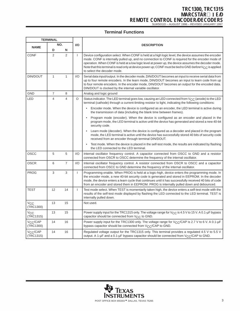
Terminal Functions
TERMINAL
NAMENO. I/O DESCRIPTION
NAMED N
CONF 2 2 I Device configuration select. When CONF is held at a high logic level, the device assumes the encodermode. CONF is internally pulled up, and no connection to CONF is required for the encoder mode ofoperation. When CONF is held at a low logic level at power up, the device assumes the decoder mode.Note that this terminal is read only at device power up; CONF must be tied to GND before VCC is appliedto select the decoder mode.
DIN/DOUT 1 1 I/O Serial data input/output. In the decoder mode, DIN/DOUT becomes an input to receive serial data fromup to four remote encoders. In the learn mode, DIN/DOUT becomes an input to learn code from upto four remote encoders. In the encoder mode, DIN/DOUT becomes an output for the encoded data.DIN/DOUT is clocked by the internal variable oscillator.
GND 7 8 Analog and logic ground
LED 4 4 O Status indicator. The LED terminal goes low, causing an LED connected from VCC (anode) to the LEDterminal (cathode) through a current-limiting resistor to light, indicating the following conditions:
• Encoder mode. When the device is configured as an encoder, the LED terminal is active duringthe transmission of data (including the blank time between frames).
• Program mode (encoder). When the device is configured as an encoder and placed in theprogram mode, the LED terminal is active until the device has generated and stored a new 40-bitsecurity code.
• Learn mode (decoder). When the device is configured as a decoder and placed in the programmode, the LED terminal is active until the device has successfully stored 40 bits of security codereceived from an encoder through terminal DIN/DOUT.
• Test mode. When the device is placed in the self-test mode, the results are indicated by flashingthe LED connected to the LED terminal.
OSCC 5 5 I/O Internal oscillator frequency control. A capacitor connected from OSCC to GND and a resistorconnected from OSCR to OSCC determine the frequency of the internal oscillator.
OSCR 6 7 I/O Internal oscillator frequency control. A resistor connected from OSCR to OSCC and a capacitorconnected from OSCC to GND determine the frequency of the internal oscillator.
PROG 3 3 I Programming enable. When PROG is held at a logic-high, device enters the programming mode. Inthe encoder mode, a new 40-bit security code is generated and stored in EEPROM. In the decodermode, the device enters a learn cycle that continues until it has successfully received 40 bits of codefrom an encoder and stored them in EEPROM. PROG is internally pulled down and debounced.
TEST 12 14 I Test mode select. When TEST is momentarily taken high, the device enters a self-test mode with theresults of the self-test mode displayed by flashing the LED connected to the LED terminal. TEST isinternally pulled down.
VCC(TRC1300)
13 15 Not used.
VCC(TRC1315)
13 15 Power supply input for the TRC1315 only. The voltage range for VCC is 4.5 V to 15 V. A 0.1-µF bypasscapacitor should be connected from VCC to GND.
VCC/CAP(TRC1300)
14 16 Power supply input for the TRC1300 only. The voltage range for VCC/CAP is 2.7 V to 6 V. A 0.1-µFbypass capacitor should be connected from VCC/CAP to GND.
VCC/CAP(TRC1315)
14 16 Regulated voltage output for the TRC1315 only. This terminal provides a regulated 4.5 V to 5.5 Voutput. A 1-µF and a 0.1-µF bypass capacitor should be connected from VCC/CAP to GND.

TRC1300, TRC1315MARCSTAR I E/DREMOTE CONTROL ENCODER/DECODERS
SLWS011D – AUGUST 1996 – REVISED JANUARY 1997
4 POST OFFICE BOX 655303 • DALLAS, TEXAS 75265
Terminal Functions
TERMINAL
NAMENO. I/O DESCRIPTION
NAMED N
VRC/TX1 8 9 I/O Function 1 VRC (valid received code) output and function 1 encode enable. In the decode mode,VRC/TX1 is an output that goes to a logic-low state (for one frame — 768 clocks) when the devicereceives the correct 40 bits of security code and function data (4 bits) matching function 1. In theencoder mode, VRC/TX1 is an input that initiates the encoding of function 1 and output of function 1data. When VRC/TX1 is pulled to GND, the device continuously outputs the function-1 code sequencestored in EEPROM memory from DIN/DOUT up to 360 times. The device cannot transmit function-1code again until VRC/TX1 is again pulled to GND. VRC/TX1 has an internal pullup resistor in both theencoder and decoder modes, and switch debouncing in the encoder mode.
VRC/TX2 9 10 I/O Function 2 VRC (valid received code) output and function 2 encode enable. In the decode mode,VRC/TX2 is an output that goes to a logic-low state (for one frame — 768 clocks) when the devicereceives the correct 40 bits of security code and function data (4 bits) matching function 2. In theencoder mode, VRC/TX2 is an input that initiates the encoding of function 2 and output of function 2data. When VRC/TX2 is pulled to GND, the device continuously outputs the function-2 code sequencestored in EEPROM memory from DIN/DOUT up to 360 times. The device cannot transmit function-2code again until VRC/TX2 is again pulled to GND. VRC/TX2 has an internal pullup resistor in both theencoder and decoder modes, and switch debouncing in the encoder mode.
VRC/TX3 10 12 I/O Function 3 VRC (valid received code) output and function 3 encode enable. In the decode mode,VRC/TX3 is an output that goes to a logic-low state (for one frame — 768 clocks) when the devicereceives the correct 40 bits of security code and function data (4 bits) matching function 3. In theencoder mode, VRC/TX3 is an input that initiates the encoding of function 3 and output of function 3data. When VRC/TX3 is pulled to GND, the device continuously outputs the function-3 code sequencestored in EEPROM memory from DIN/DOUT up to 360 times. The device cannot transmit function-3code again until VRC/TX3 is again pulled to GND. VRC/TX3 has an internal pullup resistor in both theencoder and decoder modes, and switch debouncing in the encoder mode.
VRC/TX4 11 13 I/O Function 4 VRC (valid received code) output and function 4 encode enable. In the decode mode,VRC/TX4 is an output that goes to a logic-low state (for one frame — 768 clocks) when the devicereceives the correct 40 bits of security code and function data (4 bits) matching function 4. In theencoder mode, VRC/TX4 is an input that initiates the encoding of function 4 and output of function 4data. When VRC/TX4 is pulled to GND, the device continuously outputs the function-4 code sequencestored in EEPROM memory from DIN/DOUT up to 360 times. The device cannot transmit function-4code again until VRC/TX4 is again pulled to GND. VRC/TX4 has an internal pullup resistor in both theencoder and decoder modes, and switch debouncing in the encoder mode.
absolute maximum ratings over operating free-air temperature range (unless otherwise noted) †
Supply voltage range, TRC1300, VCC (see Note 1) –0.6 V to 7 V. . . . . . . . . . . . . . . . . . . . . . . . . . . . . . . . . . . . TRC1315, VCC (see Note 1) –0.6 V to 15 V. . . . . . . . . . . . . . . . . . . . . . . . . . . . . . . . . . .
Input voltage, logic/analog signals, VI –0.6 V to 7 V. . . . . . . . . . . . . . . . . . . . . . . . . . . . . . . . . . . . . . . . . . . . . . . . . Operating free-air temperature range, TA –40°C to 85°C. . . . . . . . . . . . . . . . . . . . . . . . . . . . . . . . . . . . . . . . . . . . Storage temperature range –65°C to 150°C. . . . . . . . . . . . . . . . . . . . . . . . . . . . . . . . . . . . . . . . . . . . . . . . . . . . . . . . ESD protection, all terminals, human body 2 kV. . . . . . . . . . . . . . . . . . . . . . . . . . . . . . . . . . . . . . . . . . . . . . . . . . . .
machine 200 V. . . . . . . . . . . . . . . . . . . . . . . . . . . . . . . . . . . . . . . . . . . . . . . . . . . . . . . JEDEC latchup 120 mA or 13.2 V. . . . . . . . . . . . . . . . . . . . . . . . . . . . . . . . . . . . . . . . . . . . . . . . . . . . . . . . . . . . . . . .
† Stresses beyond those listed under “absolute maximum ratings” may cause permanent damage to the device. These are stress ratings only, andfunctional operation of the device at these or any other conditions beyond those indicated under “recommended operating conditions” is notimplied. Exposure to absolute-maximum-rated conditions for extended periods may affect device reliability.
NOTE 1: Voltage values are with respect to GND.

TRC1300, TRC1315MARCSTAR I E/D
REMOTE CONTROL ENCODER/DECODERS
SLWS011D – AUGUST 1996 – REVISED JANUARY 1997
5POST OFFICE BOX 655303 • DALLAS, TEXAS 75265
recommended operating conditions
MIN MAX UNIT
Supply voltage device configured as an encoder VCCTRC1300 2.7 6
VSupply voltage, device configured as an encoder, VCCTRC1315 2.7 15
V
Supply voltage device configured as a decoder VCCTRC1300 4.5 6
VSupply voltage, device configured as a decoder, VCCTRC1315 4.5 15
V
Low-level input voltage, VIL, at VRC/TX1–VRC/TX4, TEST, CONF, PROG 0.5 V
High-level input voltage, VIH, at VRC/TX1–VRC/TX4, TEST, CONF, PROG VCC/CAP–0.5 V
Operating free-air temperature, TA – 40 85 °C
Input voltage to amplifier/comparator, VI(PP), at DIN/DOUT 10 mV
Common-mode input voltage range, amplifier/comparator GND + 0.2 VCC/CAP–0.2 V
electrical characteristics over recommended ranges of supply voltage and free-air temperature(unless otherwise noted)
digital interfacePARAMETER TEST CONDITIONS MIN TYP MAX UNIT
VOL Low-level output voltageVRC/TX1–VRC/TX4,DIN/DOUT, LED
IOL = 5 mA 0.5 V
VOH High-level output voltageVRC/TX1–VRC/TX4,DIN/DOUT, LED
IOH = –4 mA VCC/CAP–0.5 V
DIN/DOUT 1
VRC/TX1–VRC/TX4 –20 –12 –5
IIL Low-level input current CONF VI = 0 to VIL –20 –11 –5 µA
PROG 1
TEST 1
DIN/DOUT 5 20
VRC/TX1–VRC/TX4 1
IIH High-level input current CONF VI = VIH to VCC/CAP 1 µA
PROG 2 5 8
TEST 5 12 20
decoder supply current, V CC/CAP = 6 V, TA = 25°CPARAMETER MIN TYP MAX UNIT
Supply current 1.8 2.2 mA
encoder supply current, TRC1300, V CC/CAP= 6 V, TA = 25°CPARAMETER MIN TYP MAX UNIT
Supply current, standby 35 500 nA
Supply current, code transmission 1.5 1.7 mA
encoder supply current, TRC1315, V CC = 15 V, TA = 25°CPARAMETER MIN TYP MAX UNIT
Supply current, standby 3 µA
Supply current, code transmission 1.4 1.9 mA

TRC1300, TRC1315MARCSTAR I E/DREMOTE CONTROL ENCODER/DECODERS
SLWS011D – AUGUST 1996 – REVISED JANUARY 1997
6 POST OFFICE BOX 655303 • DALLAS, TEXAS 75265
regulated output source current, TRC1315, active state, decoder mode, T A = 25°CPARAMETER TEST CONDITIONS MIN TYP MAX UNIT
Maximum current at VCC/CAP for 5 V ± 10% output VCC = 6.4 V 8 mA
Maximum current at VCC/CAP for 5 V ± 10% output VCC = 12 V 30 mA
oscillator characteristicsPARAMETER TEST CONDITIONS MIN MAX UNIT
Sample-clock frequency, f(SCLK) 5 50 kHz
Data-clock frequency, f(DCLK) 500 5000 Hz
Frequency spread (temperature VCC) using external capacitorVCC/CAP 4 V – 6 V (decoder) ±7%
Frequency spread (temperature, VCC) using external capacitorVCC/CAP 2.7 V – 6 V (encoder) ±10%
Required encoder frequency accuracy for synchronization 0.5 fRX† 2 fRX†
† fRX is decoder frequency.
encoder self programmingPARAMETER MIN MAX UNIT
Minimum time for PROG low to generate a new 40-bit security code 300 µs
EEPROM write/erase endurancePARAMETER MIN TYP MAX UNIT
Number of program cycles 100 000 1000000 cycles
EEPROM data retentionPARAMETER MIN TYP MAX UNIT
Data retention 10 years
function switch input characteristicsPARAMETER TEST CONDITION MIN TYP MAX UNIT
VCC/CAP = 5 V 7.7 µA
Pulldown current at DIN/DOUT PROG TESTVCC/CAP = 4 V 4.8 µA
Pulldown current at DIN/DOUT, PROG, TESTVCC/CAP = 3 V 2.3 µA
VCC/CAP = 2.4 V 1.3 µA
VCC/CAP = 5 V 649 kΩ
Pulldown resistor value at DIN/DOUT PROG TESTVCC/CAP = 4 V 833 kΩ
Pulldown resistor value at DIN/DOUT, PROG, TESTVCC/CAP = 3 V 1304 kΩ
VCC/CAP = 2.4 V 1846 kΩ
VCC/CAP = 5 V 7.7 µA
Pullup current at TX1 TX4 CONF LEDVCC/CAP = 4 V 4.8 µA
Pullup current at TX1–TX4, CONF, LEDVCC/CAP = 3 V 2.4 µA
VCC/CAP = 2.4 V 1.3 µA
VCC/CAP = 5 V 649 kΩ
Pullup resistor value at TX1 TX4 CONF LEDVCC/CAP = 4 V 833 kΩ
Pullup resistor value at TX1–TX4, CONF, LEDVCC/CAP = 3 V 1250 kΩ
VCC/CAP = 2.4 V 1846 kΩ

TRC1300, TRC1315MARCSTAR I E/D
REMOTE CONTROL ENCODER/DECODERS
SLWS011D – AUGUST 1996 – REVISED JANUARY 1997
7POST OFFICE BOX 655303 • DALLAS, TEXAS 75265
switching characteristics over recommended ranges of supply voltage and free-air temperature(see Figure 1)
PARAMETER MIN TYP MAX UNIT
Cycle time of sample clock (SCLK) Oscillating period 20 200 µsCycle time of sample clock (SCLK) Oscillating period 20 200 µs
tc Cycle time of data clock (DCLK) Oscillating period 200 2000 µs
tc(0) Cycle time of logic-0 symbol 3 tc µs
tc(1) Cycle time of logic-1 symbol 3 tc µs
tc(sync) Cycle time of sync pulse 2 tc µs
tw Pulse duration of dummy pulse tc µs
PARAMETER MEASUREMENT INFORMATION
tc
tc(1) tc(0)
SCLK
DCLK
DOUTVIH
VIL
tw
DCLK = SCLK ÷ 10
tc(sync)
Figure 1. Timing Diagram

TRC1300, TRC1315MARCSTAR I E/DREMOTE CONTROL ENCODER/DECODERS
SLWS011D – AUGUST 1996 – REVISED JANUARY 1997
8 POST OFFICE BOX 655303 • DALLAS, TEXAS 75265
PRINCIPLES OF OPERATION
general
Operation of the MARCSTAR I E/D devices is shown in Figure 2. The devices have two primary modes ofoperation: encoder mode and decoder mode. Additional modes and functions include programming andlearning mode, self-testing mode, security code generation, and clock generation.
Power-On Reset
CONF†
PROG†
Test Mode
Low (Decoder Mode) High (Encoder Mode)
PROG†
Low
Low
LED OnLearn Code
LED Off
DecoderLearn Path
High(PROG)
Set Flag High
PROG†
High
Decoder Mode Encoder Mode
Reset Flag
Store a New CodeLED On (2 s)
Flag
HighAttempting To Retransmit
Received-Code Path
ProgramEncoder
Path
Low
Normal Encode Path
NormalDecode Path
† = Terminals
Low
TEST†
TEST†
High(PROG)
HighHigh
LowLow
Figure 2. Top Level Operational Flow

TRC1300, TRC1315MARCSTAR I E/D
REMOTE CONTROL ENCODER/DECODERS
SLWS011D – AUGUST 1996 – REVISED JANUARY 1997
9POST OFFICE BOX 655303 • DALLAS, TEXAS 75265
PRINCIPLES OF OPERATION
general (continued)
Each of the TRC1300 and TRC1315 MARCSTAR I E/D devices can be pin-selected for operation as either anencoder on the transmitter end of a remote control system, or as a decoder on the receiver end. The interveningmedium can be a wired, RF, IR, or any other type of link with sufficient bandwidth to pass the signal. The objectiveis to transmit a function code to the remote receiver to initiate an event or for some other purpose, with thehighest level of certainty that the function code is only accepted from the matching encoder and not from anyother.
A MARCSTAR I E/D device operating in the encoder mode can send four different function codes eitherindividually or in any combination to activate up to 15 different functions at the decoder.
Once a decoder learns a security code from an encoder, it then responds only to that particular encoder. AMARCSTAR I E/D device operating in the decoder mode can learn and respond to as many as four differentencoders and provides four independent function outputs. These outputs can be further decoded (externally)to provide a 1-of-15 function output.
hopping code
The MARCSTAR I E/D devices use an advanced hopping-code algorithm to significantly increase the securitylevel of the system. The security code sent by the encoder and the security code accepted as valid by thedecoder change after each transmission. This is done independently for each of the four separate encodersecurity codes learned by the decoder.
As an encoder, the MARCSTAR I E/D is shipped from the factory with a unique 40-bit security code stored inon-board nonvolatile memory (EEPROM). Since every device shipped has a unique code, it is ready forimmediate use and requires no reprogramming. Then, each time a function input is activated, the encoderfetches the 40-bit security code from EEPROM and encrypts it. Next, the encoder assembles the data frameto be output, and then sends it out. The data frame consists of the synchronizing bits, the encrypted securitybits, the function data bits, a dummy bit, and the blank-time bits. After the data frames output ends, the encoderimmediately increments the 40-bit security code by applying the special hopping-code algorithm to it and thenstores the results in EEPROM for the next time a function input is activated. Thus, each time a function inputis activated, the 40-bit security code that is sent out is different from the security code in the previoustransmission. And with more than a trillion possible combinations, the same code is never sent twice over thelifetime of a system.
As a decoder, the MARCSTAR I E/D initially learns the 40-bit security code stored in a particular encoder byreceiving it and storing it in on-board EEPROM. Each time a security code is received from an encoder, thedevice decrypts the received 40-bit security code and compares it with the next security code expected fromany of the learned encoders. The next expected security code is calculated by applying the same hopping-codealgorithm used in the encoder to the 40-bit code stored in the decoder memory. If the received security codematches the next security code expected from one of the learned encoders, it is declared valid and the attachedfunction code is decoded. If the function code is valid, the appropriate function output or outputs are asserted.The just-received 40-bit security code is then incremented according to the algorithm, becoming the nextsecurity code expected from that encoder, and stored in EEPROM for next time. If the received security codedoes not match the next expected code from one of the learned encoders, the received function data andsecurity code are ignored.
Because the decoder activates function outputs only when the next expected code in the hopping-codesequence is received, interception and subsequent retransmission of the same code does not activate thedecoder function outputs.

TRC1300, TRC1315MARCSTAR I E/DREMOTE CONTROL ENCODER/DECODERS
SLWS011D – AUGUST 1996 – REVISED JANUARY 1997
10 POST OFFICE BOX 655303 • DALLAS, TEXAS 75265
PRINCIPLES OF OPERATION
hopping code (continued)
In some cases, the encoder is activated and sends security and function data code without the decoderreceiving and decoding the signal (if the receiver is out of range, for example). This would normally cause theencoder and decoder to fall out of sync with each other. MARCSTAR I E/D devices circumvent this by allowingthe decoder to activate the function outputs when any one of the next 256 expected security codes is receivedfrom a learned encoder. The 256 expected security codes are based on the currently-stored 40-bit securitycode. In rare cases, the encoder might be activated more than 256 times without being near the decoder,requiring the encoder and decoder pair to be manually resynchronized. In this case, the decoder can simplylearn the current encoder security code, using the procedure detailed in the decoder programming section ofthis document, resynchronizing the pair.
Hopping code provides extremely high security for the encoder/decoder pair and prevents unauthorized accessto the receiver and decoder by means of signal interception and retransmission of the intercepted signal.
Transmitter-Lock
Since the MARCSTAR I E/D devices have a pin-selectable encoder/decoder mode, a safeguard(Transmitter-Lock) has been designed into the devices. Transmitter-Lock prevents unauthorized parties fromdefeating the MARCSTAR security by using a MARCSTAR I E/D device to intercept a transmitted security codeand then transmit the next expected security code to the decoder. The received security code would then berecognized as coming from the original encoder and, therefore, valid causing the decoder function outputs tobe activated.
The safeguard works by setting an internal flag, stored in EEPROM, whenever the device, in the decoder mode,learns a code from an encoder. This flag then causes a new 40-bit security code to be generated and storedin the EEPROM if the device is later placed in the encoder mode and a transmission is ever attempted. So, oncea decoder learn cycle has occurred in a particular MARCSTAR I E/D device, the learned security code will beoverwritten by a new 40-bit security code before output in the encoder mode is permitted. This feature allowsthe MARCSTAR I E/D devices to be used as either an encoder or a decoder without sacrificing the securityprovided by separate dedicated encoder and decoder devices.
device/system security
Statistically, the probability that a random code would activate the MARCSTAR I E/D devices operating in thedecoder mode is calculated using the formula shown in equation 1.
Probability validpossible
where valid = the number of security codes that activate the device possible = the total number of possible security codes
(1)
A MARCSTAR I E/D device operating in the decoder mode responds to a total of 28 (256) security codes(including the 256-code look-ahead feature) for each of the four encoders it can learn (256 × 4 valid securitycodes).
The total number of possible 40-bit security codes is 240 (1.0995 trillion).
Inserting this into the formula gives equation 2.
Probability 28 4
240
1
230
1
1.074 109(2)
Therefore, the security of the entire system is one in 1.074 billion — there is one chance in 1.074 billion thata random security code would be recognized as valid by a MARCSTAR I E/D device operating in the decodermode.

TRC1300, TRC1315MARCSTAR I E/D
REMOTE CONTROL ENCODER/DECODERS
SLWS011D – AUGUST 1996 – REVISED JANUARY 1997
11POST OFFICE BOX 655303 • DALLAS, TEXAS 75265
PRINCIPLES OF OPERATION
encoder mode
The MARCSTAR I E/D encoder mode operational flow chart is shown in Figure 3.
Switch ActiveSleep Mode
Sample Inputs, S1 Data
Y
N
NSwitch Active
Y
Read Security Code
Encrypt Security Code
Output Sync Pulses
Output Security Code
Sample Inputs, S2 Data
Output S1 Data
Output S2 Data
Output Dummy Pulse
Wait 150 Bit Times
Switch Active
Increment Security Codeand Store in EEPROM
N
N360 Frames
Y
Y
Start
Turn TX LED On
Turn TX LED Off
Figure 3. Encoder Mode Operational Flow

TRC1300, TRC1315MARCSTAR I E/DREMOTE CONTROL ENCODER/DECODERS
SLWS011D – AUGUST 1996 – REVISED JANUARY 1997
12 POST OFFICE BOX 655303 • DALLAS, TEXAS 75265
PRINCIPLES OF OPERATION
encoder mode (continued)
TRC1300 and TRC1315 MARCSTAR I E/D devices are configured as an encoder by holding the CONF terminalhigh or by not connecting CONF and allowing the internal pullup to hold it high (a connection to CONF is notrequired to select the encoder mode).
In the encoder mode, the device sends a maximum of 360 frames of data out through the DIN/DOUT terminalwhen one or any combination of VRC/TX1 – VRC/TX4 terminals is pulled low — when buttons on a remotetransmitter are pressed, for example. The following list and Figure 4 detail the response to various button-pressinputs.
When a button is pressed, a maximum of 360 frames of data are sent.
Multiple button presses can occur during the output of the 360 frames.
If all buttons are released before all 360 frames are sent, output of data ceases at that point and the timeoutcounter resets.
If any buttons are still pressed after all 360 frames have been sent, no additional data is sent and the timeoutcounter is not reset.
The timeout counter resets only when all buttons are released, allowing the device to enter a low-powerstandby mode while it waits to detect a button press.
n FramesLess than
1 Frame
1 Frame343 DCLKs 360 Frame Max
>360 Frames
n Frames
EncoderVRC/TX1-4
EncoderDOUT
EncoderLED
Figure 4. Encoder Timing

TRC1300, TRC1315MARCSTAR I E/D
REMOTE CONTROL ENCODER/DECODERS
SLWS011D – AUGUST 1996 – REVISED JANUARY 1997
13POST OFFICE BOX 655303 • DALLAS, TEXAS 75265
PRINCIPLES OF OPERATION
encoder mode (continued)
Two or more buttons can be pressed at the same time to activate additional functions. Since it is not possibleto press them at exactly the same time, a form of debouncing ensures that only a single function code is receivedas valid. Function data is sent in two 12-bit packets. The first function-data packet is derived from the first sampleof the buttons (S1) at the beginning of the frame, and the second function-data packet is derived from the secondsample of the buttons (S2) immediately after the 40-bit security code (see Figure 5). This gives an effective 168data-clock debounce time because the MARCSTAR I E/D, configured as a decoder, activates function outputsonly when the two function data packets in the frame are identical. When valid function data has been receivedin the first packet but the second packet in a frame contains different function data (caused by a second buttonbeing down at sample 2 time), both data packets are discarded and the decoder function outputs remain in theirprevious state.
VRC/TX1 –VRC/TX4
(active low)
DIN/DOUT 360 Frames
48 Bits 40 Symbols (120 bits)
Precode(Sync)
Security Code
Frame Data (193 Bits)
S1 – ButtonSample 1
150 Zero Bits
One Complete Frame (343 Bits)
4 Symbols(12 Bits)
Data Packet 1 Data Packet 2
4 Symbols(12 Bits)
Dummy Pulse (1 Bit)
Function Data (24 Bits)
Blank-Time (150 Bits)
25 Bits
S2 – Button Sample 2
Figure 5. Transmitted Data Format
If the user is holding buttons B1 and B2 on the transmitter down, both the first button sample (S1) and the secondbutton sample (S2) should find both buttons down as the next frame is prepared and sent. So, the next framethat is transmitted should contain the same function data in both the first and the second function data packets,and the decoder activates function outputs 1 and 2. So as an example, if transmitter button B1 activates the doorlocks, button B2 activates the alarm, and both button B1 and button B2 pressed at the same time activates thetrunk lock, the MARCSTAR sampling/debouncing function prevents the door locks and alarm from beingactivated when the user intent is to activate only the trunk lock.
TRC1300, TRC1315MARCSTAR I E/DREMOTE CONTROL ENCODER/DECODERS
SLWS011D – AUGUST 1996 – REVISED JANUARY 1997
14 POST OFFICE BOX 655303 • DALLAS, TEXAS 75265
PRINCIPLES OF OPERATION
encoder timing
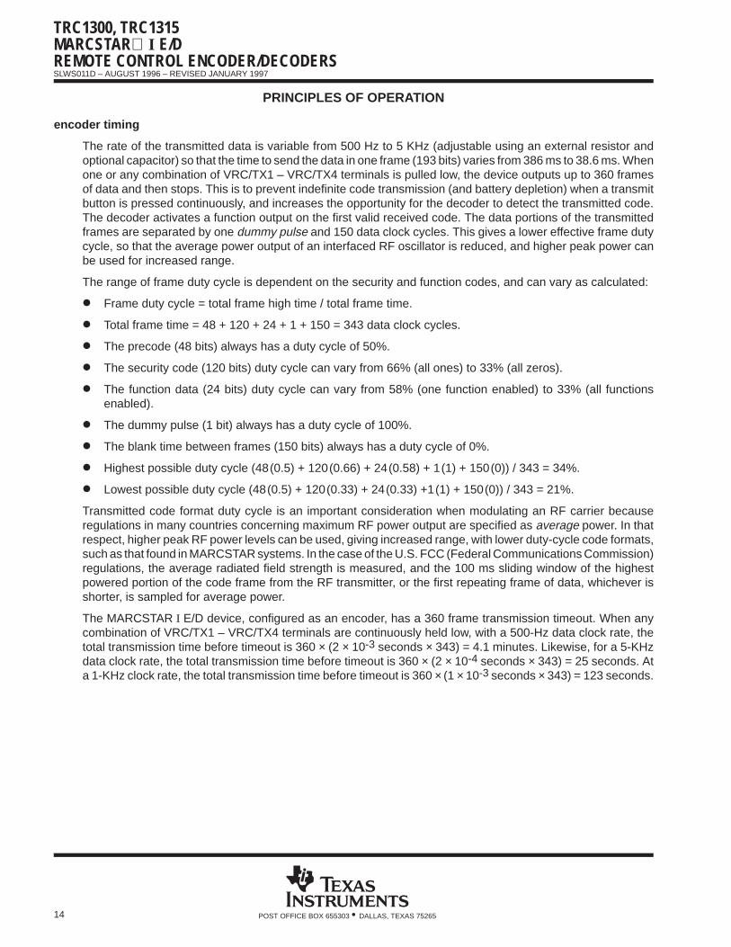
The rate of the transmitted data is variable from 500 Hz to 5 KHz (adjustable using an external resistor andoptional capacitor) so that the time to send the data in one frame (193 bits) varies from 386 ms to 38.6 ms. Whenone or any combination of VRC/TX1 – VRC/TX4 terminals is pulled low, the device outputs up to 360 framesof data and then stops. This is to prevent indefinite code transmission (and battery depletion) when a transmitbutton is pressed continuously, and increases the opportunity for the decoder to detect the transmitted code.The decoder activates a function output on the first valid received code. The data portions of the transmittedframes are separated by one dummy pulse and 150 data clock cycles. This gives a lower effective frame dutycycle, so that the average power output of an interfaced RF oscillator is reduced, and higher peak power canbe used for increased range.
The range of frame duty cycle is dependent on the security and function codes, and can vary as calculated:
Frame duty cycle = total frame high time / total frame time.
Total frame time = 48 + 120 + 24 + 1 + 150 = 343 data clock cycles.
The precode (48 bits) always has a duty cycle of 50%.
The security code (120 bits) duty cycle can vary from 66% (all ones) to 33% (all zeros).
The function data (24 bits) duty cycle can vary from 58% (one function enabled) to 33% (all functionsenabled).
The dummy pulse (1 bit) always has a duty cycle of 100%.
The blank time between frames (150 bits) always has a duty cycle of 0%.
Highest possible duty cycle (48(0.5) + 120(0.66) + 24(0.58) + 1(1) + 150(0)) / 343 = 34%.
Lowest possible duty cycle (48(0.5) + 120(0.33) + 24(0.33) +1(1) + 150(0)) / 343 = 21%.
Transmitted code format duty cycle is an important consideration when modulating an RF carrier becauseregulations in many countries concerning maximum RF power output are specified as average power. In thatrespect, higher peak RF power levels can be used, giving increased range, with lower duty-cycle code formats,such as that found in MARCSTAR systems. In the case of the U.S. FCC (Federal Communications Commission)regulations, the average radiated field strength is measured, and the 100 ms sliding window of the highestpowered portion of the code frame from the RF transmitter, or the first repeating frame of data, whichever isshorter, is sampled for average power.
The MARCSTAR I E/D device, configured as an encoder, has a 360 frame transmission timeout. When anycombination of VRC/TX1 – VRC/TX4 terminals are continuously held low, with a 500-Hz data clock rate, thetotal transmission time before timeout is 360 × (2 × 10-3 seconds × 343) = 4.1 minutes. Likewise, for a 5-KHzdata clock rate, the total transmission time before timeout is 360 × (2 × 10-4 seconds × 343) = 25 seconds. Ata 1-KHz clock rate, the total transmission time before timeout is 360 × (1 × 10-3 seconds × 343) = 123 seconds.
TRC1300, TRC1315MARCSTAR I E/D
REMOTE CONTROL ENCODER/DECODERS
SLWS011D – AUGUST 1996 – REVISED JANUARY 1997
15POST OFFICE BOX 655303 • DALLAS, TEXAS 75265
PRINCIPLES OF OPERATION
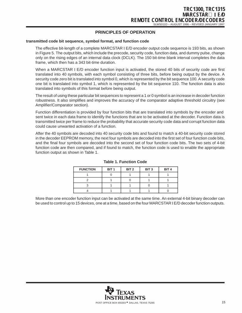
transmitted code bit sequence, symbol format, and function code
The effective bit-length of a complete MARCSTAR I E/D encoder output code sequence is 193 bits, as shownin Figure 5. The output bits, which include the precode, security code, function data, and dummy pulse, changeonly on the rising edges of an internal data clock (DCLK). The 150 bit-time blank interval completes the dataframe, which then has a 343 bit-time duration.
When a MARCSTAR I E/D encoder function input is activated, the stored 40 bits of security code are firsttranslated into 40 symbols, with each symbol consisting of three bits, before being output by the device. Asecurity code zero bit is translated into symbol 0, which is represented by the bit sequence 100. A security codeone bit is translated into symbol 1, which is represented by the bit sequence 110. The function data is alsotranslated into symbols of this format before being output.
The result of using these particular bit sequences to represent a 1 or 0 symbol is an increase in decoder functionrobustness. It also simplifies and improves the accuracy of the comparator adaptive threshold circuitry (seeAmplifier/Comparator section).
Function differentiation is provided by four function bits that are translated into symbols by the encoder and sent twice in each data frame to identify the functions that are to be activated at the decoder. Function data istransmitted twice per frame to reduce the probability that accurate security code data and corrupt function datacould cause unwanted activation of a function.
After the 40 symbols are decoded into 40 security code bits and found to match a 40-bit security code storedin the decoder EEPROM memory, the next four symbols are decoded into the first set of four function code bits,and the final four symbols are decoded into the second set of four function code bits. The two sets of 4-bitfunction code are then compared, and if found to match, the function code is used to enable the appropriatefunction output as shown in Table 1.
Table 1. Function Code
FUNCTION BIT 1 BIT 2 BIT 3 BIT 4
1 0 1 1 1
2 1 0 1 1
3 1 1 0 1
4 1 1 1 0
More than one encoder function input can be activated at the same time. An external 4-bit binary decoder canbe used to control up to 15 devices, one at a time, based on the four MARCSTAR I E/D decoder function outputs.

TRC1300, TRC1315MARCSTAR I E/DREMOTE CONTROL ENCODER/DECODERS
SLWS011D – AUGUST 1996 – REVISED JANUARY 1997
16 POST OFFICE BOX 655303 • DALLAS, TEXAS 75265
PRINCIPLES OF OPERATION
decoder mode
The MARCSTAR I E/D decoder mode operational flow is shown in Figure 6.
Wait for Dummy Pulse
Measure Sync Pulse
N
Identify Valid Sync
Sync Complete
Y
8 Valid SyncPulses
Y
Receive Security Code
Valid Code
Receive S1 Data
Receive S2 Data
Data Valid
Start
Update Security Code
Reset Frame Counter
Wait for Dummy Pulse
Assert Outputs
Y
Y
N
N
N
Figure 6. Decoder Mode Operational Flow

TRC1300, TRC1315MARCSTAR I E/D
REMOTE CONTROL ENCODER/DECODERS
SLWS011D – AUGUST 1996 – REVISED JANUARY 1997
17POST OFFICE BOX 655303 • DALLAS, TEXAS 75265
PRINCIPLES OF OPERATION
decoder mode (continued)
The TRC1300 and TRC1315 MARCSTAR I E/D devices are configured as a decoder by holding the CONFterminal low before the device is powered up (the device reads the CONF terminal during POR, power-on reset).
In the decoder mode, the device receives serial data from input terminal DIN/DOUT. The input data signal isfirst passed through the internal amplifier/comparator for signal conditioning before being decoded andcompared with the four 40-bit security codes stored in EEPROM memory. When a match is found with one ormore received data frames, the appropriate function output terminals, VRC/TX1 – VRC/TX4, are enabled(active-low). The decoder activates a function output only when two identical function data packets are receivedin the same frame. The function output remains active for a minimum period of 768 data clock cycles, whichcan range from 154 ms to 1.54 seconds, depending on the clock frequency used. With a 1-KHz data clock rate,for example, a function output is asserted for a minimum of 768 ms. The decoder keeps the appropriate functionoutput terminals (VRC/TX1 – VRC/TX4) active as long as it receives valid code, and through the blank timebetween each frame, which is 150 clock cycles. The function outputs go inactive when invalid function data codeis received.
Configured as a decoder, the MARCSTAR I E/D samples the incoming serial data at 10 times the expectedtransmitted data rate. As each symbol is sampled, an integrator determines if it represents a 1 or 0 by the totalnumber of high and low samples. A high symbol (110) has a high level for approximately two-thirds of the symbolperiod, while a low symbol (100) is high for only one-third of the symbol period. Therefore, if five or more outof eight of the samples are high, the symbol is decoded as a 1, and if three or fewer of the samples are high,the symbol is decoded as a 0. The symbol format also improves synchronization of the decoder with theincoming serial data. A transition from low to high always signifies the beginning of a symbol.
The method of synchronization employed by MARCSTAR I E/D uses a precode sync pattern that precedes thesecurity and function data portions of each frame sent by the encoder. The precode consists of 24 pulses witha 50% duty cycle, each being high or low for one period of the data clock. This equates to a total of 48 bit times.
amplifier/comparator
A representation of the amplifier/comparator section of the MARCSTAR I E/D devices is shown in Figure 7. Thiscircuit is used to amplify and wave-shape low-level input signals to logic levels for input to the shift registers.The internal R1 and C1 components combination form a reference-setting (autobias) network, and the timeconstant of this network is about three symbols, or 12 bits of code. The internal components R2 and C2 forma low-pass network with a time constant equal to approximately one-tenth of one DCLK period so thathigh-frequency transients are attenuated before reaching the comparator.
_+
_+
R2
R1
C1 C2
To ShiftRegisters
Amplifier/ComparatorUnity-Gain
Buffer
INDIN/DOUT
Figure 7. Amplifier/Comparator Equivalent Schematic
TRC1300, TRC1315MARCSTAR I E/DREMOTE CONTROL ENCODER/DECODERS
SLWS011D – AUGUST 1996 – REVISED JANUARY 1997
18 POST OFFICE BOX 655303 • DALLAS, TEXAS 75265
PRINCIPLES OF OPERATION
amplifier/comparator (continued)
The amplifier/comparator is implemented with advanced switched-capacitor technology. This is done for twoprimary reasons. First, since the TRC1300 and TRC1315 devices are variable frequency, the values of R1, C1,R2, and C2 must change depending on the received data rate. Since they are a switched-capacitor design, thefilter characteristics scale depending on the oscillator in the decoder device, which must match the encoderoscillator frequency. With this scheme, the amplifier/comparator section functions at all received code datarates. The second reason for using switched-capacitor filters is the increased accuracy and precise filterresponse that they provide.
programming mode
The MARCSTAR I E/D devices have been designed so that no programming station is required to load thesecurity codes into the EEPROM memory. When the device is configured as an encoder, it generates a 40-bitsecurity code and stores it in EEPROM memory. When configured as a decoder, the device learns the securitycode from up to four different encoders.
EEPROM stored-code format
The EEPROM memory contains four banks that are used for 40 bits of security code for each of the four channelsand an additional 32 bits (eight bits per channel) for error detection. The total EEPROM memory is 192 bits.When configured as a decoder, these EEPROM banks store up to four learned 40-bit security codes; whenconfigured as an encoder, only the first bank of 40 bits is used for the security code.
programming — encoder
When a MARCSTAR I E/D device is configured as an encoder and placed in the programming mode, itgenerates a 40-bit security code and stores it in the first 40-bit EEPROM memory bank. The remaining three40-bit memory banks are unused. An LED connected to the LED terminal is required to verify a proper writesequence to EEPROM. The LED anode should be connected to the positive supply and the cathode should beconnected to the LED terminal of the MARCSTAR I E/D through a current-limiting resistor.
The procedure for programming a MARCSTAR I E/D device configured as an encoder is described in thefollowing steps:
1. Connect the proper RC combination to the OSCR and OSCC terminals to set the frequency of theinternal oscillator.
2. Connect GND and then apply VCC.
3. Apply a logic high to PROG (the PROG terminal is internally pulled down and debounced). The deviceassumes the program mode. The LED lights, the device generates a new 40-bit security code internally,it loads the first memory bank with that code, and then extinguishes the LED.
4. The MARCSTAR I E/D encoder is now programmed with a new 40-bit security code. Each time step 3 isrepeated, a new 40-bit security code is generated and then loaded into the first EEPROM memorylocation, overwriting the previous security code.
TRC1300, TRC1315MARCSTAR I E/D
REMOTE CONTROL ENCODER/DECODERS
SLWS011D – AUGUST 1996 – REVISED JANUARY 1997
19POST OFFICE BOX 655303 • DALLAS, TEXAS 75265
PRINCIPLES OF OPERATION
programming — smart decoder (learn mode)
The MARCSTAR I E/D configured as a smart decoder has the capability of learning up to four 40-bit securitycodes from four separate encoders. If the decoder attempts to learn a fifth encoder security code, the decoderlogic overwrites the first stored security code with the fifth encoder security code. This FIFO (first in, first out)operation always causes the oldest code to be overwritten. When an encoder is lost and a new encoder islearned by the decoder, all four of the encoders now being used with the decoder should be relearned to ensurethat the decoder contains all the current encoder security codes and no longer stores the security code fromthe lost encoder. When there are fewer than four encoders being used with a particular decoder, any of themcan be learned more than once (for a total of four) to fill the remaining decoder security code storage locationsand ensure that the code for the lost encoder has been overwritten.
Each 40-bit security code is loaded into a EEPROM in a single write sequence. An LED connected to the LEDterminal is required to verify a proper write sequence to EEPROM memory. The LED anode should beconnected to positive supply and the cathode to the LED terminal of the MARCSTAR I E/D through acurrent-limiting resistor (the LED terminal is active low).
The procedure to write each 40-bit security code into the decoder EEPROM is as follows:
1. Connect the proper RC combination to the OSCR and OSCC terminals to set the frequency of theinternal oscillator.
2. Connect the CONF terminal to GND. CONF, which is internally pulled up, must be tied to GND before thedevice is powered up so that when the internal microcontroller reads the CONF terminal during POR(power on reset), CONF will already be at GND.
3. Connect the device to system GND and then VCC.
4. Apply a logic high to PROG (the PROG terminal is internally pulled down and debounced). The deviceassumes the program mode and the LED lights. The PROG terminal must be held at logic high for theduration of the programming sequence.
5. Apply the MARCSTAR I E/D encoder security code data to be programmed to DIN/DOUT. The firstreceived frame of data is decoded into a 40-bit security code sequence and loaded into the first memorybank of the EEPROM. The LED turns off after the device has decoded and stored the received data. Thelogic high should now be removed from the PROG terminal. The LED stays on if an attempt is made toexit the programming mode without learning a code.
6. To learn up to four encoder security codes, repeat steps 4 and 5. Each time the device is programmed,the next available memory bank is used, up to four banks.
NOTE: In order to prevent unauthorized programming of the decoder, it is suggested that access to the learn mode be limited to themanufacturer or dealer. In cases where end-user programming is required, a key-switch can limit programming to authorizedindividuals only.
TRC1300, TRC1315MARCSTAR I E/DREMOTE CONTROL ENCODER/DECODERS
SLWS011D – AUGUST 1996 – REVISED JANUARY 1997
20 POST OFFICE BOX 655303 • DALLAS, TEXAS 75265
PRINCIPLES OF OPERATION
oscillator
An internal variable-rate clock runs at the SCLK (sample clock) frequency, and is adjustable from 5 kHz to50 kHz. DCLK (data clock) is derived from SCLK so that both clocks are synchronous. DCLK runs at one-tenththe speed of SCLK and clocks the transmitted data at a rate variable from 500 bps to 5 kbps. SCLK is used tosample the received data at 10 times the received data rate. The high sampling rate in the decoder combinedwith the symbol code format and the internal signal-conditioning amplifier circuitry provides accurate correlationof the received signal. The SCLK frequency is set by an external RC at terminals OSCR and OSCC.
The encoder and decoder should be set to the same clock rates; however, the device allows a wide frequencytolerance to increase the robustness of the communications link. The encoder can vary from one-half to twotimes the decoder clock speed and synchronization still results. This allows for internal oscillator tolerance andfrequency change due to external component tolerances and temperature changes. For example, if a serial dataspeed of 1.5 kbps (DCLK) is desired, then both the encoder and the decoder oscillators (SCLK) must be setto be 10 times the data rate frequency, or 15 kHz. Both the encoder and decoder can vary ±33% in frequency,or from 10 kHz to 20 kHz, and the devices still synchronize successfully. For the worst case example, theencoder SCLK would be running at 10 kHz and the decoder SCLK at 20 kHz, or twice the encoder frequency.The absolute maximum and minimum clock frequency of 5 kHz to 50 kHz must never be violated. Because thedevice introduces up to ±7% frequency variation, the external RC components can have as much as ±26%tolerance, for a total of ±33% frequency variation.
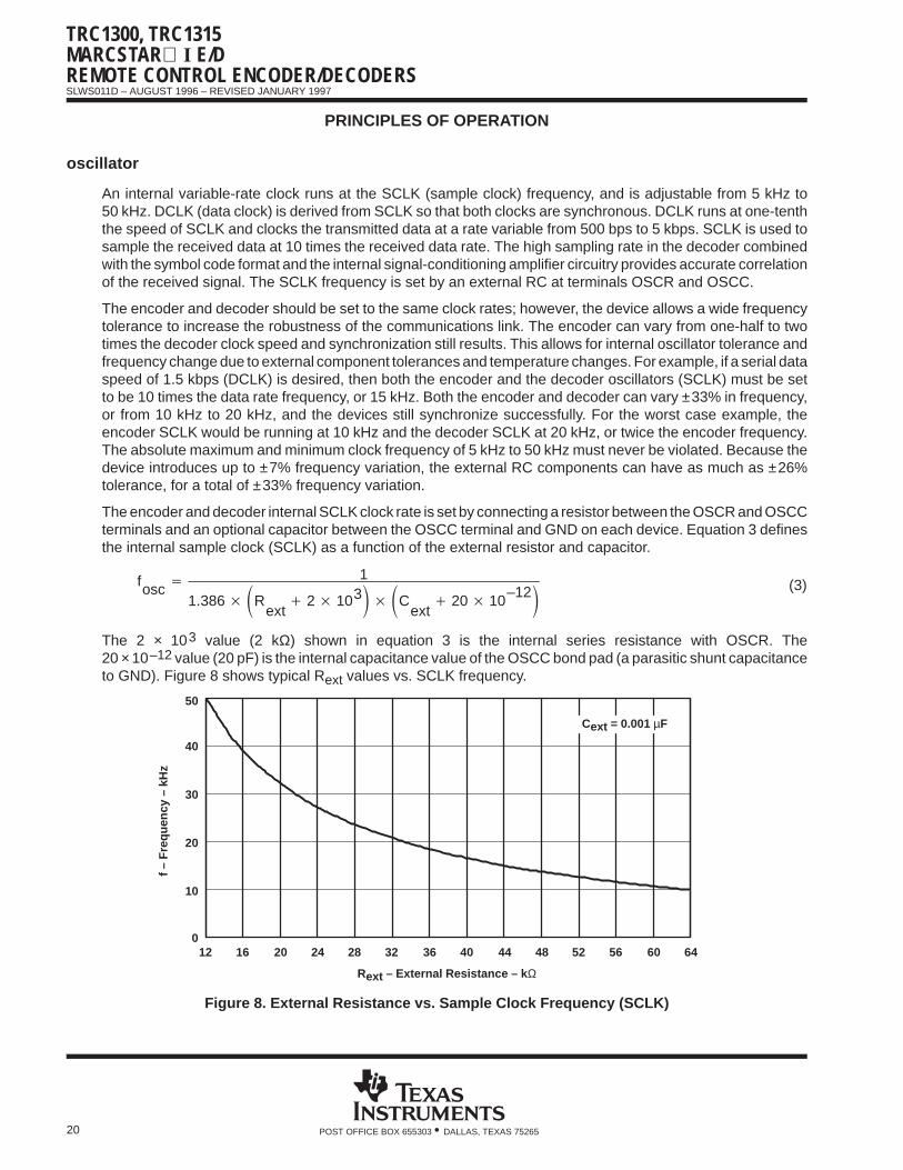
The encoder and decoder internal SCLK clock rate is set by connecting a resistor between the OSCR and OSCCterminals and an optional capacitor between the OSCC terminal and GND on each device. Equation 3 definesthe internal sample clock (SCLK) as a function of the external resistor and capacitor.
fosc 1
1.386 Rext
2 103 Cext
20 10–12 (3)
The 2 × 10³ value (2 kΩ) shown in equation 3 is the internal series resistance with OSCR. The20 × 10–12 value (20 pF) is the internal capacitance value of the OSCC bond pad (a parasitic shunt capacitanceto GND). Figure 8 shows typical Rext values vs. SCLK frequency.
12 16 20 24 28 32 36 40 44 48 52 56 60 640
10
20
30
40
50
f – F
requ
ency
– k
Hz
Rext – External Resistance – k Ω
Cext = 0.001 µF
Figure 8. External Resistance vs. Sample Clock Frequency (SCLK)

TRC1300, TRC1315MARCSTAR I E/D
REMOTE CONTROL ENCODER/DECODERS
SLWS011D – AUGUST 1996 – REVISED JANUARY 1997
21POST OFFICE BOX 655303 • DALLAS, TEXAS 75265
PRINCIPLES OF OPERATION
test mode
TRC1300 and TRC1315 MARCSTAR I E/D devices are equipped with a self-test function that checks the RAM,ROM, and EEPROM memory areas:
The RAM is tested by writing checkerboard bit patterns into the RAM and then reading them back. The testis passed if the correct data is read from the RAM.
The ROM is tested by calculating a new checksum for each location containing data and then comparingit to a predetermined value. The test is passed if the two values match.
The EEPROM is tested by calculating a new checksum for each of the four 40-bit locations and comparingthem with checksum values stored in EEPROM. The test is passed if the two values match.
When TEST is momentarily held at VCC, the device enters the self-test mode. While in this mode, the deviceruns through the tests and then indicates results with a flashing LED. The result codes are shown in Table 2.
Table 2. LED Flashing Self-Test Error Codes
LED FLASHES CONDITION
0 No tests passed
1 Passed EEPROM test only
2 Passed ROM test only
3 Passed ROM and EEPROM tests
4 Passed RAM test only
5 Passed RAM and EEPROM tests
6 Passed RAM and ROM tests
7 Passed all tests
The switch that initiates the test mode should be momentary — the device continues to run through the testsas long as TEST is held at VCC.

TRC1300, TRC1315MARCSTAR I E/DREMOTE CONTROL ENCODER/DECODERS
SLWS011D – AUGUST 1996 – REVISED JANUARY 1997
22 POST OFFICE BOX 655303 • DALLAS, TEXAS 75265
APPLICATION INFORMATION
4-channel, direct-wired
Figure 9 shows an example of MARCSTAR I E/D devices in a single-wire direct connection. This configurationis typically used in cable-box decoders, remote lighting, and wired home-security-system applications. U1 isa TRC1300 configured as an encoder by not connecting the CONF terminal (which is internally pulled up, sono connection is required). U2, a TRC1315, is configured as a decoder by tying CONF low (CONF must be lowbefore VCC is applied). PROG is held low by an internal pulldown to disable the program mode. Closing theLearn switch places U2 in the program mode so that the security code from an encoder can be learned. Boththe encoder and decoder are set to a 2-kHz data clock (DCLK) frequency (20 kHz sample clock, SCLK) usingan external RC at OSCC and OSCR. An LED is connected through a resistor to the LED terminal of the encoderand indicates transmission of code. When momentary switches S1– S4 are pressed, the corresponding outputson the U2 decoder go low and LEDs D1–D4 light.
3 V
0.001 µF
33 kΩ
Channel 4
Channel 3
Channel 2
Channel 1
More Than One SwitchCan Be Pressed At a
TimeVR
C/T
X1
VR
C/T
X2
VR
C/T
X3
VR
C/T
X4
OS
CR
OS
CC
CC
VDIN
/DO
UT
CO
NF
PR
OG
LED
TE
ST
/CA
P
GN
D
14 5 6 11 10 9 8
1 2 3 4 12 13 7
VR
C/T
X1
VR
C/T
X2
VR
C/T
X3
VR
C/T
X4
OS
CR
OS
CC
DIN
/DO
UT
CO
NF
PR
OG
LED
TE
ST
GN
D
14 5 6 11 10 9 8
1 2 3 4 12 13 7
TX RX
Learn
D1–D4
R1–R4220 kΩ
U1 TRC1300 (encoder) U2 TRC1315 (decoder)
CC
V
/CA
PC
CV
CC
V
0.001 µF
1 µF 0.1 µF0.1 µF
12 V
1 kΩ1 kΩ
0.1 µF
33 kΩ
NOTE A: Terminal numbers are for the D package.
Figure 9. A 4-Channel, Single-Wire Connection
TRC1300, TRC1315MARCSTAR I E/D
REMOTE CONTROL ENCODER/DECODERS
SLWS011D – AUGUST 1996 – REVISED JANUARY 1997
23POST OFFICE BOX 655303 • DALLAS, TEXAS 75265
APPLICATION INFORMATION
4-channel, infrared or RF connection
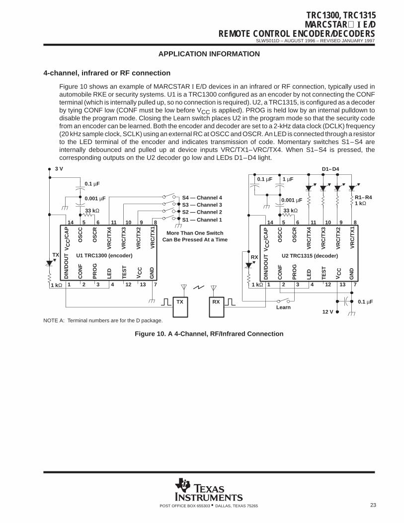
Figure 10 shows an example of MARCSTAR I E/D devices in an infrared or RF connection, typically used inautomobile RKE or security systems. U1 is a TRC1300 configured as an encoder by not connecting the CONFterminal (which is internally pulled up, so no connection is required). U2, a TRC1315, is configured as a decoderby tying CONF low (CONF must be low before VCC is applied). PROG is held low by an internal pulldown todisable the program mode. Closing the Learn switch places U2 in the program mode so that the security codefrom an encoder can be learned. Both the encoder and decoder are set to a 2-kHz data clock (DCLK) frequency(20 kHz sample clock, SCLK) using an external RC at OSCC and OSCR. An LED is connected through a resistorto the LED terminal of the encoder and indicates transmission of code. Momentary switches S1–S4 areinternally debounced and pulled up at device inputs VRC/TX1–VRC/TX4. When S1–S4 is pressed, thecorresponding outputs on the U2 decoder go low and LEDs D1–D4 light.
3 V
0.001 µF
33 kΩ
S4 — Channel 4S3 — Channel 3S2 — Channel 2S1 — Channel 1
More Than One SwitchCan Be Pressed At a Time
VR
C/T
X1
VR
C/T
X2
VR
C/T
X3
VR
C/T
X4
OS
CR
OS
CC
DIN
/DO
UT
CO
NF
PR
OG
LED
GN
D
14 5 6 11 10 9 8
1 2 3 4 12 13 7
VR
C/T
X1
VR
C/T
X2
VR
C/T
X3
VR
C/T
X4
OS
CR
OS
CC
DIN
/DO
UT
CO
NF
PR
OG
LED
GN
D
14 5 6 11 10 9 8
1 2 3 4 12 13 7
TX RX
0.001 µF
33 kΩ
D1–D4
R1–R41 kΩ
U1 TRC1300 (encoder) U2 TRC1315 (decoder)
TX RX
TE
ST
CC
VTE
ST
/CA
PC
CV
CC
V
/CA
PC
CV
1 kΩ
0.1 µF 1 µF
1 kΩ
Learn
0.1 µF
12 V
0.1 µF
NOTE A: Terminal numbers are for the D package.
Figure 10. A 4-Channel, RF/Infrared Connection

TRC1300, TRC1315MARCSTAR I E/DREMOTE CONTROL ENCODER/DECODERS
SLWS011D – AUGUST 1996 – REVISED JANUARY 1997
24 POST OFFICE BOX 655303 • DALLAS, TEXAS 75265
APPLICATION INFORMATION
16-channel, infrared or RF connection
Figure 11 shows an example of MARCSTAR I E/D devices in a 16-channel infrared or RF connection, typicallyused in consumer electronics (TV, VCR, etc.) or remote-control toy applications. U1 is a TRC1300 configuredas an encoder by not connecting the CONF terminal (which is internally pulled up, so no connection is required).U2, a TRC1315, is configured as a decoder by tying CONF low (CONF must be low before VCC is applied).PROG is held low by an internal pulldown to disable the program mode. Closing the Learn switch places U2in the program mode so that the security code from an encoder can be learned. Both the encoder and decoderare set to a 2-kHz data clock (DCLK) frequency (20 kHz sample clock, SCLK) using an external RC at OSCCand OSCR. An LED is connected to the LED terminal of the encoder and indicates transmission of code. Theoutputs of a 4-bit binary encoder are connected to inputs VRC/TX1–VRC/TX4 of the MARCSTAR I E/D encoder.When one of the 16 momentary switches (S1–S16) is pressed, the binary equivalent is encoded by U3 andapplied to the MARCSTAR I E/D encoder (U1) inputs. The binary equivalent is transmitted to the MARCSTARI E/D decoder (U2) where the corresponding outputs go low. The inputs of a 4-bit binary decoder are connectedto the VRC/TX1–VRC/TX4 outputs of the MARCSTAR I E/D decoder. When these terminals output the receivedbinary function data, they are then decoded by U4, and the appropriate U4 output is activated. The outputs canbe used to control one of 15 devices at a time, or for a 15 position semiproportional control.
3 V
0.001 µF
33 kΩ
VR
C/T
X1
VR
C/T
X2
VR
C/T
X3
VR
C/T
X4
OS
CR
OS
CC
DIN
/DO
UT
CO
NF
PR
OG
LED
GN
D
14 5 6 11 10 9 8
1 2 3 4 12 13 7
VR
C/T
X1
VR
C/T
X2
VR
C/T
X3
VR
C/T
X4
OS
CR
OS
CC
DIN
/DO
UT
CO
NF
PR
OG
LED
GN
D
14 5 6
1 2 3 4 12 13 7
TX RX
33 kΩ
R1–R422 kΩ
TX RX
QD
QC
QBQA
U3 S1
One Switch ata Time May BePressed
U4 4-Bit Binary Decoder
4-BitBinaryEncoder
/CA
PC
CV
TE
ST
CC
V
CC
VTE
ST
/CA
PC
CV
QD QC QB QA
Output 1 Output 16
S16
Learn
1 kΩ1 kΩ
U1 TRC1300 (encoder) U2 TRC1315 (decoder)
0.001 µF
0.1 µF 1 µF
0.1 µF
12 V
0.1 µF
11 10 9 8
NOTE A: Terminal numbers are for the D package.
Figure 11. A 16-Channel, RF or Infrared Connection

TRC1300, TRC1315MARCSTAR I E/D
REMOTE CONTROL ENCODER/DECODERS
SLWS011D – AUGUST 1996 – REVISED JANUARY 1997
25POST OFFICE BOX 655303 • DALLAS, TEXAS 75265
MECHANICAL DATAD (R-PDSO-G**) PLASTIC SMALL-OUTLINE PACKAGE14 PIN SHOWN
4040047/B 03/95
0.228 (5,80)0.244 (6,20)
0.069 (1,75) MAX0.010 (0,25)0.004 (0,10)
1
14
0.014 (0,35)0.020 (0,51)
A
0.157 (4,00)0.150 (3,81)
7
8
0.044 (1,12)0.016 (0,40)
Seating Plane
0.010 (0,25)
PINS **
0.008 (0,20) NOM
A MIN
A MAX
DIM
Gage Plane
0.189(4,80)
(5,00)0.197
8
(8,55)
(8,75)
0.337
14
0.344
(9,80)
16
0.394(10,00)
0.386
0.004 (0,10)
M0.010 (0,25)
0.050 (1,27)
0°–8°
NOTES: A. All linear dimensions are in inches (millimeters).B. This drawing is subject to change without notice.C. Body dimensions do not include mold flash or protrusion, not to exceed 0.006 (0,15).D. Four center pins are connected to die mount pad.E. Falls within JEDEC MS-012
TRC1300, TRC1315MARCSTAR I E/DREMOTE CONTROL ENCODER/DECODERS
SLWS011D – AUGUST 1996 – REVISED JANUARY 1997
26 POST OFFICE BOX 655303 • DALLAS, TEXAS 75265
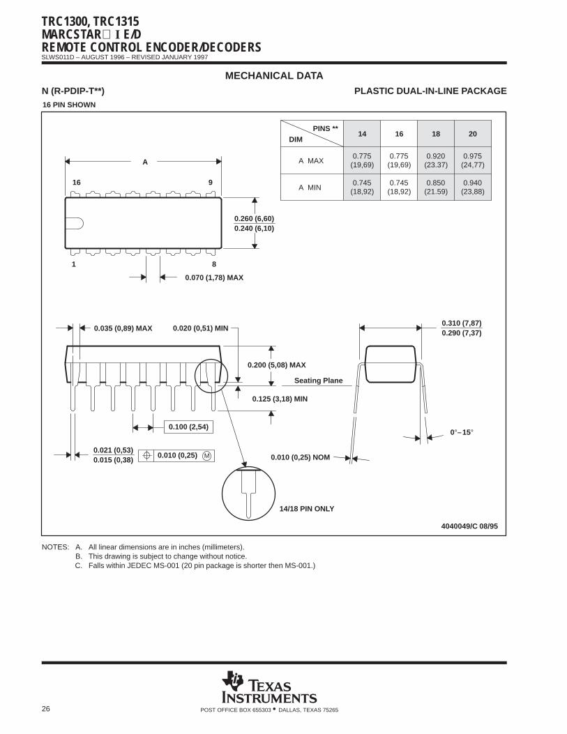
MECHANICAL DATAN (R-PDIP-T**) PLASTIC DUAL-IN-LINE PACKAGE
20
0.975(24,77)
0.940(23,88)
18
0.920
0.850
14
0.775
0.745
(19,69)
(18,92)
16
0.775(19,69)
(18,92)0.745
A MIN
DIM
A MAX
PINS **
0.310 (7,87)0.290 (7,37)
(23.37)
(21.59)
Seating Plane
0.010 (0,25) NOM
14/18 PIN ONLY
4040049/C 08/95
9
8
0.070 (1,78) MAX
A
0.035 (0,89) MAX 0.020 (0,51) MIN
16
1
0.015 (0,38)0.021 (0,53)
0.200 (5,08) MAX
0.125 (3,18) MIN
0.240 (6,10)0.260 (6,60)
M0.010 (0,25)
0.100 (2,54)0°–15°
16 PIN SHOWN
NOTES: A. All linear dimensions are in inches (millimeters).B. This drawing is subject to change without notice.C. Falls within JEDEC MS-001 (20 pin package is shorter then MS-001.)
IMPORTANT NOTICE
Texas Instruments and its subsidiaries (TI) reserve the right to make changes to their products or to discontinueany product or service without notice, and advise customers to obtain the latest version of relevant informationto verify, before placing orders, that information being relied on is current and complete. All products are soldsubject to the terms and conditions of sale supplied at the time of order acknowledgement, including thosepertaining to warranty, patent infringement, and limitation of liability.
TI warrants performance of its semiconductor products to the specifications applicable at the time of sale inaccordance with TI’s standard warranty. Testing and other quality control techniques are utilized to the extentTI deems necessary to support this warranty. Specific testing of all parameters of each device is not necessarilyperformed, except those mandated by government requirements.
CERTAIN APPLICATIONS USING SEMICONDUCTOR PRODUCTS MAY INVOLVE POTENTIAL RISKS OFDEATH, PERSONAL INJURY, OR SEVERE PROPERTY OR ENVIRONMENTAL DAMAGE (“CRITICALAPPLICATIONS”). TI SEMICONDUCTOR PRODUCTS ARE NOT DESIGNED, AUTHORIZED, ORWARRANTED TO BE SUITABLE FOR USE IN LIFE-SUPPORT DEVICES OR SYSTEMS OR OTHERCRITICAL APPLICATIONS. INCLUSION OF TI PRODUCTS IN SUCH APPLICATIONS IS UNDERSTOOD TOBE FULLY AT THE CUSTOMER’S RISK.
In order to minimize risks associated with the customer’s applications, adequate design and operatingsafeguards must be provided by the customer to minimize inherent or procedural hazards.
TI assumes no liability for applications assistance or customer product design. TI does not warrant or representthat any license, either express or implied, is granted under any patent right, copyright, mask work right, or otherintellectual property right of TI covering or relating to any combination, machine, or process in which suchsemiconductor products or services might be or are used. TI’s publication of information regarding any thirdparty’s products or services does not constitute TI’s approval, warranty or endorsement thereof.
Copyright 1998, Texas Instruments Incorporated