mathematical model of blood flow through a composite ... · 60 rupesh k. srivastav
TRANSCRIPT
58
Available at
http://pvamu.edu/aam Appl. Appl. Math.
ISSN: 1932-9466
Vol. 9, Issue 1 (June 2014), pp. 58-74
Applications and Applied
Mathematics:
An International Journal
(AAM)
Mathematical Model of Blood Flow through a Composite Stenosis in
Catheterized Artery with Permeable Wall
Rupesh K. Srivastav Department of Mathematics
Ambalika Institute of Management & Technology
Integral University
Lucknow-226001, India
Received: August 19, 2013; Accepted: January 17, 2014
Abstract
The present mathematical analysis, the study of blood flow through the model of a composite
stenosed catheterized artery with permeable wall, has been performed to investigate the blood
flow characteristics. The expressions for the blood flow characteristics-the impedance (resistance
to flow), the wall shear stress distribution in stenosis region, the shear stress at the throat of the
stenosis have been derived. The results obtained are displayed graphically and discussed briefly.
Keywords: Stenosis; catheter; permeable wall; Darcy number; slip parameter
MSC2010: 76Z05
1. Introduction
The cause and development of many cardiovascular diseases, most common types are ischemia,
angina pectoris, myocardial infraction and cerebral strokes, are related to the nature of blood
flow and mechanical behavior of the blood vessel wall, that is why the study of the blood flow
through a stenosed artery is very important. The generic medical term stenosis or arteriosclerosis
is the narrowing of any body passage, tube or orifice; comes from the Greek words arthero
(meaning gruel or paste) and sclerosis (hardness). A common form of arterial narrowing or
stenosis is that caused by atheroma, a deposition of fats and fibrous tissue in the arterial lumen.
Such constriction of the arterial lumen grows inward and restricts the normal flow of blood
AAM: Intern. J., Vol. 9, Issue 1 (June 2014) 59
where the transport of blood to the region beyond the narrowing is reduced considerably.
Moreover, under normal physiological conditions, the transport of blood in the human
circulatory system depends entirely on the pumping action of the heart which produces a
pressure gradient throughout the arterial system.
Since the first investigation of Mann et al. (1938), a large number of studies including the
important contributions of Young (1968,1979), Young and Tsai (1973), Caro et al. (1978),
Shukla et al.(1980), Ahmed and Giddens (1983), Sarkar and Jayaraman (1998), Pralhad and
Schultz (2004), Jung et al. (2004), Liu et al. (2004) Srivastava and coworkers (1996, 2009,
2010a,b), Mishra et al. (2006), Ponalagusamy (2007), Layek et al. (2005, 2009), Joshi et al.
(2009), Mekheimer and El-Kot (2008), Tzirtzilakis (2008), Mandal and coworkers (2005, 2007a,
b), Politis et al. (2007, 2008), Siddiqui et al. (2009), Singh et al. (2010), Medhavi (2011) and
many others, have been conducted in the literature in various context.
It has been established that the development of stenosis in its early stage of the disease, is
strongly related to the characteristics of the blood flow by [Gidden et al. (1993)]. It is reported
that at high shear rates and in larger vessel, blood behaves like a Newtonian fluid, [Taylor
(1959)], [Young (1968)] has analyzed the effects of stenosis on flow characteristics of blood
treating blood as a Newtonian fluid. He reported that an increase in the stenosis size increases
both the impedance to flow and wall shear stress.
The insertion of a catheter into an artery forms the annular region between the catheter wall and
the arterial wall. A catheter is composed of polyster based thermoplastic polyurethane, medical
grade polyvinyl choloride, etc. The insertion of the catheter will change the flow field, modify
the pressure distribution and increase the resistance. Even though the catheter tool devices are
used for the measurement of arterial blood pressure or pressure gradient and flow velocity or
flow rate, X-ray angiography and intravascular ultrasound diagnosis and coronary ballon
angioplasty treatment of various arterial diseases, a little attention has been given in literature to
the flow in catheterized arteries.
Kanai et al. (1970), has reported that when a catheter is inserted in a stenosed artery, it further
increases the impedance to flow and changes the pressure distribution. Jayaraman and Tewari
(1995) have studied blood flow in a catheterized curved artery, by assuming the artery as a
curved pipe and the catheter to be co-axial to it. Young and Tsai (1973), Lee (1974), Mcdonald
(1979), Ahmad and Giddens (1983), Ponalagusami (1986), Back (1994) and Back et al. (1996)
studied the mean flow resistance increase during coronary artery catheterization in normal as
well as stenosed arteries. Srivastava and Srivastava (2009) have presented a brief review of the
literature on artery catheterization with and without stenosis. Layek et al. (2009) investigated the
effect of an overlapping stenosis on flow characteristics considering the pressure variation in
both the radial and axial direction of the arterial segment under consideration. Srivastava et al.
(2010) investigated the effect on flow characteristics of blood due to the presence of overlapping
stenosis in an artery assuming that the flowing blood is represented by Newtonian fluid.
The plasma membrane is a thin elastic membrane around the cell which usually allows the
movement of small irons and molecules of various substances through it. This nature of plasma
membrane is termed as ‘permeability’. The flow in the permeable boundary is described by
60 Rupesh K. Srivastav
Darcy law which states that the rate at which a fluid flows through a permeable substance per
unit area is equal to the permeability times the pressure drop per unit length of flow, divided by
the viscosity of fluid. Most recently, Srivastava et al. (2009) studied impedance and wall shear
stress in blood flow through a bell shaped stenosis in an artery with permeable wall.
In view of the above discussion, the research reported here is devoted to the study of blood flow
through a composite stenosis in catheterized artery with permeable wall; the flow in the
permeable boundary is described by Darcy law; assuming that blood is represented by a
Newtonian fluid.
2. Formulation of the Problem
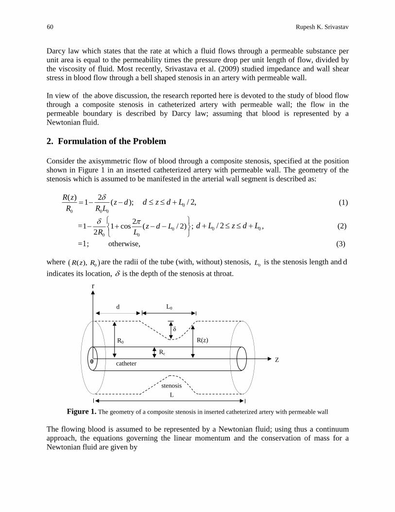
Consider the axisymmetric flow of blood through a composite stenosis, specified at the position
shown in Figure 1 in an inserted catheterized artery with permeable wall. The geometry of the
stenosis which is assumed to be manifested in the arterial wall segment is described as:
0 0 0
( ) 21 ( );
R zz d
R R L
0 / 2,d z d L (1)
=0
0 0
21 1 cos ( / 2) ;
2z d L
R L
0 0/ 2d L z d L , (2)
=1; otherwise, (3)
where 0( ), R z R are the radii of the tube (with, without) stenosis, 0L is the stenosis length and d
indicates its location, is the depth of the stenosis at throat.
Figure 1. The geometry of a composite stenosis in inserted catheterized artery with permeable wall
The flowing blood is assumed to be represented by a Newtonian fluid; using thus a continuum
approach, the equations governing the linear momentum and the conservation of mass for a
Newtonian fluid are given by
Rc
catheter
R(z)
δ
0
stenosis
r
d L0
Z
R0
L
AAM: Intern. J., Vol. 9, Issue 1 (June 2014) 61
2 ,u u u p
u v ut z r z
(4)
2
2
1( ) ,
v v v pu v v
t z r r r
(5)
0,v v u
r r z
(6)
where 2 =2 2 2 2/ (1/ )( / ) /r r r z is a two-dimensional Laplacian operator, r is the
radial coordinate measured in the direction normal to the tube axis, ( ,u v ) denotes the (axial,
radial) components of velocity of the fluid, p is the pressure, ρ and μ are respectively the fluid
density and the viscosity.
Due to the non-linearity of convective acceleration terms, to obtain the solution of equations (4)–
(6) is a formidable task. Depending, therefore, on the size of the stenosis, however, certain terms
in these equations are of less importance than other (Young, 1968). Considering thus the case of
a mild stenosis 0( / 1)R , the general constitutive equations (4)-(6) in the case of an
axisymmetric, laminar, steady one-dimensional flow of blood in an artery reduce (Young, 1968;
Srivastava and Rastogi, 2009) to
r
ur
rrdz
dp
1
(7)
where u is the axial velocity, is the fluid viscosity, r is the radial co-ordinate and p is the
pressure.
The condition that are specified at the artery wall and the interface for present study may now be
stated (Beavers and Joseph, 1967; Srivastava et al., 2012) as
,at , 0 cRru
(8)
),(at , )(r
and zRruuD
uuu porousB
a
B
(9)
where ,dz
dpDu a
porous
porousu is the velocity in the permeable boundary,
Bu is the slip
velocity, aD is the Darcy number and , called slip parameter, is a dimensionless quantity
depending on the material parameters which characterize the structure of the permeable material
within the boundary region.
62 Rupesh K. Srivastav
3. Analysis
Using boundary conditions (8) and (9), the expression for the velocity obtained as solution of
equation (7), is given as
2 2
2 21 ( ) log( )log 1 .
4 log( ) log( )
cB
c c
dp R R r r Ru R r u
dz R R R R R
(10)
Also the slip velocity, Bu is determined as
2 21 ( ) 1
2 4 .4 log( ) { 1 log( )}
cB a
c a c
dp R Ru R D
dz R R R D R R R
(11)
An application of equation (10) into (11), yields
2 22 2
2 2
( ) log( )log 1
log( ) log( )1.
4 ( ) 1 2 4
log( ) log( )
c
c c
ca
c ca
R R r r RR r
R R R R Rdpu
dz R RR D
R R R R R RD
(12)
The volumetric flow rate, Q is now calculated as
R
Rc
urdrQ 2
,
4
)log(
2
)log(log
2
)log(
11
8
2
0
24
2
0
22
2
0
2
0
22
0
4
04
0
RRRRR
RRRRRR
R
RRR
R
dz
dpRQ
c
ccc
(13)
where 0R
Rc , and 2 2( ) 1
2 4 .log( ) log( )
ca
c ca
R RR D
R R R R R RD
From equation (13), one now obtains
)(
84
0
zR
Q
dz
dp
,
(14)
AAM: Intern. J., Vol. 9, Issue 1 (June 2014) 63
where )(
1)(
zz
and with
4 2
2
2 2
0 0 0 0
2 22 4
2 2
0 0
1 2 21
log( ) log( ) log( )( ) .
4
log( )
c c c
c
R R
R R R R R R R R R Rz
R R R R
The pressure drop, Lz, -pzpp at 0at across the stenosis in the tube of length, L is
obtained as
4
00
8
R
Qdz
dz
dpp
L
,
(15)
where
0 0
0 00 0 0 0
/2
0 /21 from 1 from 2 1
[ ( )] [ ( )] [ ( )] [ ( )] .
d L d Ld L
d d L d LR R R R R R R R
z dz z dz z dz z dz
The first and the fourth integrals in the expression obtained above are straight forward whereas
the analytical evaluation of second and third integrals are almost a formidable task and therefore
shall be evaluated numerically.
The flow resistance (resistive impedance), , the wall shear stress in stenotic region, w , and
shearing stress at stenotic throat, s are now calculated as
dzzdzzLL
RQ
p
RR
Ld
LdRR
Ld
d )2( from 2/)1( from
2/
0
4
00
0
00
0
)]([ )]([ 8
, (16)
)(
4
2 0
3
0
zR
R
R
Q
dz
dpRw
, (17)
00 1ws ]τ[τ RRR . (18)
Following now the reports of Srivastava et al. (2009), one derives the expressions for the
impedance, , the wall shear stress in the stenotic region, w , and shearing stress at stenotic
throat, s in their non-dimensional form as
64 Rupesh K. Srivastav
dzzdzzL
LL
RR
Ld
LdRR
Ld
d )2( from 2/)1( from
2/
0
0
0
00
0
)]([ )]([ 11
, (19)
,
4)log(
2
)log()log(
2
)log(
11
)(
2
0
24
2
0
2
0
2
2
0
0
2
00
2
00
4
0
0
RRRRR
RRRRRR
R
RRR
R
RRw
(20)
0 01[ ]s w R R R , (21)
where,
0 , 0) ,() ,( swsw , ),2(4
1 02
0
a
aDR
R
D
,
)log()(
1
4
)log()(
)()(2
00
0
000
2
0
2
0
0
2
0
RRRRD
R
R
D
RRRR
RRRR
R
R
R
a
ac
,12
)21(log
11 1 4
2
0
2
2
0
22
RR
and 0 4
0
8and
L
R
3
0
0
4
R
Q
are, respectively, the resistive impedance and wall shear stress
for an uncatheterized normal artery (no stenosis).
In the absence of the catheter (i.e., under the limit 0 ), one derives the expressions for , w ,
respectively, through a stenosed artery with permeable wall as
,
)2(4
)()(
11
0
2
0
2
0
2
0
0
Ld
d
a
aDR
R
DRRRR
dz
L
LL
(22)
AAM: Intern. J., Vol. 9, Issue 1 (June 2014) 65
,
)2(4
)( )(
2
0
2
00
a
a
w
DRR
DRRRR
(23)
00 1ws ]τ[τ RRR . (24)
4. Numerical Results and Discussion
The development of a stenosis in an artery can obviously create many serious problems and in
general disrupt the normal function of the circulatory system. In order to observe the quantitative
effects of the various parameters involved in the present analysis, computer codes are developed
to evaluate the analytical results obtained in equations (19)-(21) for dimensionless resistance to
flow, , the wall shear stress , w , in the stenotic region, the shear stress, s , at the throat of the
stenosis in a tube of radius R0 = 0.01cm for various parameter values: d = 0; L0(cm) =1; L (cm) =
1, 2, 5; (non-dimensional catheter radius)= 0.1, 0.2, 0.3, 0.4, 0.5; = 0.1, 0.2, 0.3, 0.4, 0.5;
aD (square root of Darcy number, Da and hereafter referred as Darcy number) = 0.1, 0.2, 0.3,
0.4, 0.5; 0R = 0, 0.05, 0.10, 0.15, 0.20.
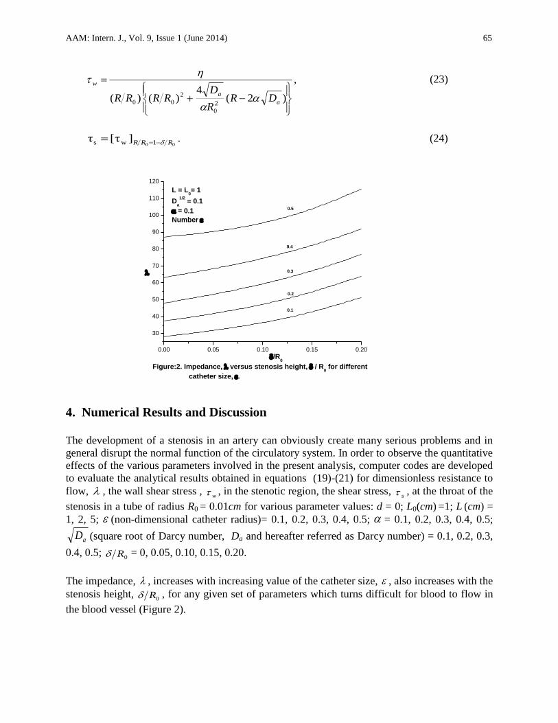
The impedance, , increases with increasing value of the catheter size, , also increases with the
stenosis height, 0R , for any given set of parameters which turns difficult for blood to flow in
the blood vessel (Figure 2).
0.00 0.05 0.10 0.15 0.20
30
40
50
60
70
80
90
100
110
120
L = L0= 1
Da
1/2 = 0.1
= 0.1
Number
Figure:2. Impedance, versus stenosis height, / R0 for different
catheter size, .
0.1
0.2
0.3
0.4
/R0
0.5
66 Rupesh K. Srivastav
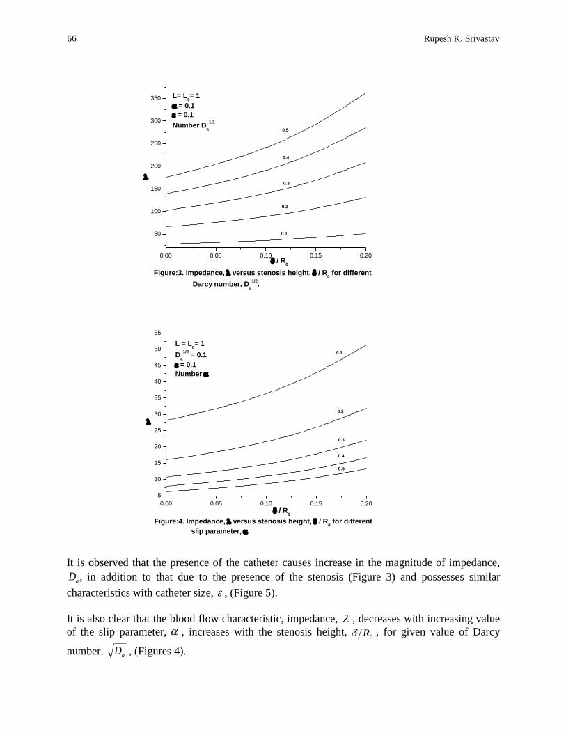
It is observed that the presence of the catheter causes increase in the magnitude of impedance,
,aD in addition to that due to the presence of the stenosis (Figure 3) and possesses similar
characteristics with catheter size, , (Figure 5).
It is also clear that the blood flow characteristic, impedance, , decreases with increasing value
of the slip parameter, , increases with the stenosis height, 0R , for given value of Darcy
number, aD , (Figures 4).
0.00 0.05 0.10 0.15 0.20
5
10
15
20
25
30
35
40
45
50
55
0.1
0.2
0.3
0.4
0.5
Figure:4. Impedance, versus stenosis height, / R0 for different
slip parameter, .
/ R0
L = L0= 1
Da
1/2 = 0.1
= 0.1
Number
0.00 0.05 0.10 0.15 0.20
50
100
150
200
250
300
350
0.1
0.2
0.3
0.5
0.4
L= L0= 1
= 0.1
= 0.1
Number Da
1/2
Figure:3. Impedance, versus stenosis height, / R0 for different
Darcy number, Da
1/2.
/ R0
AAM: Intern. J., Vol. 9, Issue 1 (June 2014) 67
0.1 0.2 0.3 0.4 0.5
30
40
50
60
70
80
90
100
110
0.05
0.1
0.15
0.2
0
Figure:5. Impedance, versus catheter size, for different
stenosis height, / R0 .
L= L0= 1
= 0.1
Da
1/2 = 0.1
Number / R0
0.1 0.2 0.3 0.4 0.5
5
10
15
20
25
30
35
40
45
50
55
Figure: 7. Impedance, versus slip parameter, for different
stenosis height, / R0 .
0
0.05
0.10
0.15
L= L0= 1
Da
1/2 = 0.1
= 0.1
Number / R0
0.20
0.1 0.2 0.3 0.4 0.5
40
80
120
160
200
240
280
320
360
Da
1/2
Figure:6. Impedance, versus Darcy number, Da
1/2 for different
stenosis height, / R0 .
0
0.05
0.10
0.15
0.20
L= L0= 1
= 0.1
= 0.1
Number / R0
68 Rupesh K. Srivastav
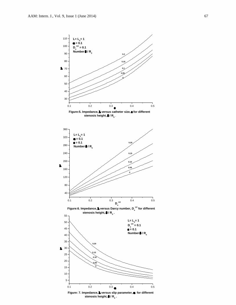
For other given set of parameters, the blood flow characteristic, λ, increases with increasing
Darcy number, aD , (Figure:6). One observes that the flow resistance, , decreases rapidly
with increasing value of the slip parameter from its maximal amplitude at 1.0 (Figure:7).
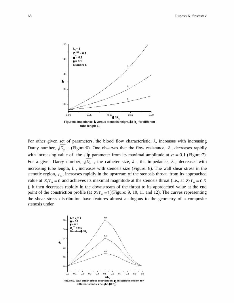
For a given Darcy number, aD , the catheter size, , the impedance, , decreases with
increasing tube length, L , increases with stenosis size (Figure: 8). The wall shear stress in the
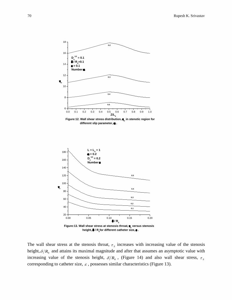
stenotic region, w , increases rapidly in the upstream of the stenosis throat from its approached
value at 00 LZ and achieves its maximal magnitude at the stenosis throat (i.e., at 5.00 LZ
), it then decreases rapidly in the downstream of the throat to its approached value at the end
point of the constriction profile (at 10 LZ )(Figure: 9, 10, 11 and 12). The curves representing
the shear stress distribution have features almost analogous to the geometry of a composite
stenosis under
0.00 0.05 0.10 0.15 0.20
30
35
40
45
50
5
1
2
Figure:8. Impedance, versus stenosis height, / R0 for different
tube length L .
/ R0
L0= 1
Da
1/2 = 0.1
= 0.1
= 0.1
Number L
0.0 0.1 0.2 0.3 0.4 0.5 0.6 0.7 0.8 0.9 1.0
28
30
32
34
36
38
w
0.10
0.15
0.20
Figure:9. Wall shear stress distribution, w in stenotic region for
different stenosis height, / R0.
Z/L0
L = L0= 1
= 0.1
= 0.1
Da
1/2 = 0.1
Number / R0

AAM: Intern. J., Vol. 9, Issue 1 (June 2014) 69
consideration. The wall shear stress are found to be compressive in nature and they are all
downwardly concave.
0.0 0.1 0.2 0.3 0.4 0.5 0.6 0.7 0.8 0.9 1.0
30
40
50
60
70
80
90
100
0.1
0.2
0.3
0.4
0.5
w
Figure:10. Wall shear stress distribution, w in stenotic region
for different catheter size, .
Z/L0
Number
/ R0=0.1
Da
1/2 = 0.1
= 0.1
0.0 0.1 0.2 0.3 0.4 0.5 0.6 0.7 0.8 0.9 1.0
40
60
80
100
120
140
160
180
200
Nunber Da
1/2
0.1
0.2
0.5
0.4
0.3
Z/L0
= 0.1
/ R0=0.1
= 0.1
Figure:11. Wall shear stress distribution, w in stenotic region for
different Darcy number Da
1/2.
w
70 Rupesh K. Srivastav
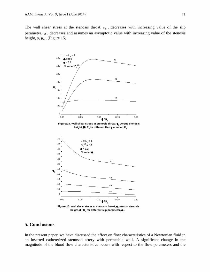
The wall shear stress at the stenosis throat, S
increases with increasing value of the stenosis
height,0R and attains its maximal magnitude and after that assumes an asymptotic value with
increasing value of the stenosis height, 0R , (Figure 14) and also wall shear stress,
S
corresponding to catheter size, , possesses similar characteristics (Figure 13).
0.00 0.05 0.10 0.15 0.20
20
40
60
80
100
120
140
160
180
s
0.1
0.2
0.3
0.4
0.5
Figure:13. Wall shear stress at stenosis throat, S versus stenosis
height, / R0for different catheter size, .
/ R0
L = L0 = 1
= 0.2
Da
1/2 = 0.2
Number
0.0 0.1 0.2 0.3 0.4 0.5 0.6 0.7 0.8 0.9 1.0
6
8
10
12
14
16
18
Figure:12. Wall shear stress distribution, w in stenotic region for
different slip parameter, .
Da
1/2 = 0.1
/ R0=0.1
= 0.1
Number
0.2
0.5
0.4
0.3
Z/L0
w
AAM: Intern. J., Vol. 9, Issue 1 (June 2014) 71
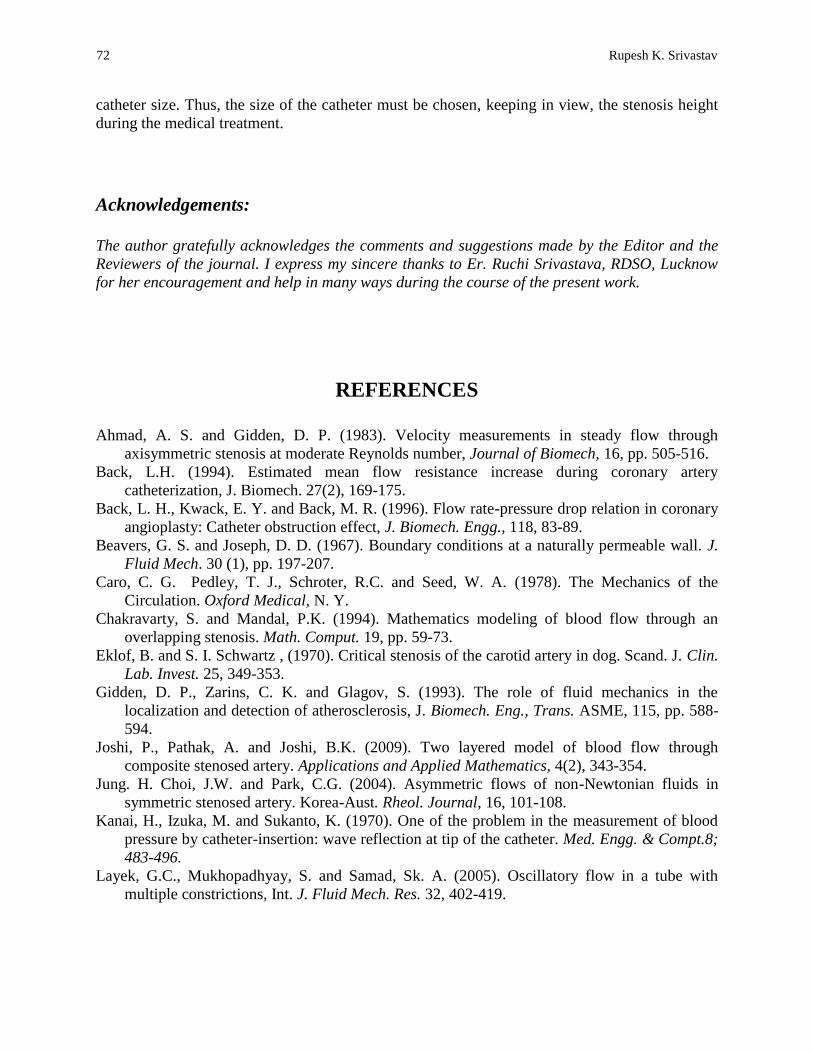
The wall shear stress at the stenosis throat, S ,
decreases with increasing value of the slip
parameter, , decreases and assumes an asymptotic value with increasing value of the stenosis
height,0R , (Figure 15).
5. Conclusions
In the present paper, we have discussed the effect on flow characteristics of a Newtonian fluid in
an inserted catheterized stenosed artery with permeable wall. A significant change in the
magnitude of the blood flow characteristics occurs with respect to the flow parameters and the
0.00 0.05 0.10 0.15 0.20
0
20
40
60
80
100
120
1400.3
0.2
0.1
Figure:14. Wall shear stress at stenosis throat, S versus stenosis
height, / R0for different Darcy number, D
a.
/ R0
S
L = L0 = 1
= 0.1
= 0.2
Number Da
1/2
0.00 0.05 0.10 0.15 0.20
8
10
12
14
16
18
20
22
24
26
28
30
0.5
0.4
0.3
0.2
Figure:15. Wall shear stress at stenosis throat, S versus stenosis
height, / R0 for different slip parameter, .
/ R0
S
L = L0 = 1
Da
1/2 = 0.1
= 0.2
Number
72 Rupesh K. Srivastav
catheter size. Thus, the size of the catheter must be chosen, keeping in view, the stenosis height
during the medical treatment.
Acknowledgements:
The author gratefully acknowledges the comments and suggestions made by the Editor and the
Reviewers of the journal. I express my sincere thanks to Er. Ruchi Srivastava, RDSO, Lucknow
for her encouragement and help in many ways during the course of the present work.
REFERENCES
Ahmad, A. S. and Gidden, D. P. (1983). Velocity measurements in steady flow through
axisymmetric stenosis at moderate Reynolds number, Journal of Biomech, 16, pp. 505-516.
Back, L.H. (1994). Estimated mean flow resistance increase during coronary artery
catheterization, J. Biomech. 27(2), 169-175.
Back, L. H., Kwack, E. Y. and Back, M. R. (1996). Flow rate-pressure drop relation in coronary
angioplasty: Catheter obstruction effect, J. Biomech. Engg., 118, 83-89.
Beavers, G. S. and Joseph, D. D. (1967). Boundary conditions at a naturally permeable wall. J.
Fluid Mech. 30 (1), pp. 197-207.
Caro, C. G. Pedley, T. J., Schroter, R.C. and Seed, W. A. (1978). The Mechanics of the
Circulation. Oxford Medical, N. Y.
Chakravarty, S. and Mandal, P.K. (1994). Mathematics modeling of blood flow through an
overlapping stenosis. Math. Comput. 19, pp. 59-73.
Eklof, B. and S. I. Schwartz , (1970). Critical stenosis of the carotid artery in dog. Scand. J. Clin.
Lab. Invest. 25, 349-353.
Gidden, D. P., Zarins, C. K. and Glagov, S. (1993). The role of fluid mechanics in the
localization and detection of atherosclerosis, J. Biomech. Eng., Trans. ASME, 115, pp. 588-
594.
Joshi, P., Pathak, A. and Joshi, B.K. (2009). Two layered model of blood flow through
composite stenosed artery. Applications and Applied Mathematics, 4(2), 343-354.
Jung. H. Choi, J.W. and Park, C.G. (2004). Asymmetric flows of non-Newtonian fluids in
symmetric stenosed artery. Korea-Aust. Rheol. Journal, 16, 101-108.
Kanai, H., Izuka, M. and Sukanto, K. (1970). One of the problem in the measurement of blood
pressure by catheter-insertion: wave reflection at tip of the catheter. Med. Engg. & Compt.8;
483-496.
Layek, G.C., Mukhopadhyay, S. and Samad, Sk. A. (2005). Oscillatory flow in a tube with
multiple constrictions, Int. J. Fluid Mech. Res. 32, 402-419.
AAM: Intern. J., Vol. 9, Issue 1 (June 2014) 73
Layek, G.C., Mukhopadhyay, S. and Gorla, R.S.R. (2009). Unsteady viscous flow with variable
viscosity in a vascular tube with an overlapping constriction. Int. J. Engg. Sci. 47, pp. 649-
659.
Lee, J. S. (1974). On the coupling and Detection of motion between an artery with a localized
lesion and its surrounding Tissue. J. Biomech.7, 403.
Liu, G.T., Wang, X.J., Ai, B.Q. and Liu, L.G. (2004). Numerical study of pulsating flow through
a tapered artery with stenosis. Chin. Journal Phys., 42, 401-409.
Mann, F. C., Herrick, J. F., Essex, H. E. and Blades. E. J. (1938). Effects on blood flow of
decreasing the lumen of blood vessels. Surgery 4, pp. 249-252.
Mandal, P.K., Chakravarty, S. and Mandal, A. (2007a). Numerical study on the unsteady flow of
non-Newtonian fluid through diffrerently shaped arterial stenosis. Int. J. Comput. Math. 84,
1059-1077.
Mandal, P.K., Chakravarty, S., Mandal, A. and Amin, A. ( 2007b) . Effect of body acceleration
on unsteady pulsatile flow of non-Newtonian fluid through a stenosed artery. Appl. Math.
Comput. 189, 766-779.
Medhavi, A.(2011). On macroscopic two-phase arterial blood flow through an overlapping
stenosis. E-Journal of Science and Technology 6, 19-31.
Mekheimer, Kh. S. and El-Kot. (2008). Magnetic field and hall currents influences on blood flow
through a stenotic arteries, Applied Mathematics and Mechanics, 29, 1-12.
Misra, J.C. and Shit, G.C. (2006). Blood flow through arteries in a pathological state: A
theoretical study. Int. J. Engg. Sci. 44, 662-671.
Politis, A. K., Stavropoulos, G. P., Christolis, M. N., Panagopoulos, F. G., Vlachos, N. S., and
Markatos, N. C. (2007). Numerical modeling of simulated blood flow in idealized composite
arterial coronary grafts: Steady state simulations. J. Biomech., 40(5), 1125–1136.
Politis, A. K., Stavropoulos, G. P., Christolis, M. N. Panagopoulos, F. G., Vlachos, N. S.
and Markatos, N. C. (2008). Numerical modeling of simulated blood flow in idealized
composite arterial coronary grafts: Transient flow. J. Biomechanics. 41(1), 25-39.
Ponalagusamy, R. (2007). Blood flow through an artery with mild stenosis: A two layered
model, different shapes of stenosis and slip velocity at the wall. J Appl. Sci. 7(7), 1071-1077.
Pralhad, R.N. and Schultz, D.H. (2004). Modeling of arterial stenosis and its applications to
blood diseases. Math. Biosci., 190, 203-220.
Robard, S. (1996). Dynamics of blood flow in stenotic lesions. Am. Heart J. 72, 698.
Sarkar, A. and Jayaraman, G. (1998). Corretion to flow rate-pressure drop in coronary
angioplasty; steady streaming effect. Journal of Biomechanics, 31, 781-791.
Singh, B., Joshi, P. and Joshi, B.K. (2010). Blood flow through an artery having radially non-
summetric mild stenosis. Appl. Math. Sci. 4(22), 1065-1072.
Shukla, J. B., Parihar, R. S. and Gupta, S. P. (1980). Effects of peripheral layer viscosity on
blood flow thorough the arterywith mild stenosis. Bull. Math. Biol. 42, 797-805.
Siddiqui, S. U., Verma, N. K., Mishra, S. and Gupta, R. S. (2009). “Mathematical modelling of
pulsatile flow of blood through a time dependent stenotic blood vessel,” Int. J. of Phy. Sci.,
Vol. 21, No.1, pp. 241-248.
Srivastava, V. P. and Rastogi, R. (2010, a). Blood flow through stenosed catheterized artery:
effect of haematocrit and stenosis shape. Comput. Math. Appl. 59, 1377-1385.
Srivastava, V. P. and Rastogi, R. (2009). Effects of hemtocrit on impedance and shear stress
during stenosed artery catheterization. Appl. Appl. Math. 4(1), pp.98-113.

74 Rupesh K. Srivastav
Srivastava, V. P., Tandon, Mala, and Srivastav, Rupesh, K. (2012). A macroscopic two-phase
blood flow through a bell shaped stenosis in an artery with permeable wall. Appl. Appl.
Math. 7(1), pp. 37-51.
Srivastav, V. P., Vishnoi, Roachana, Mishra, Shailesh, Sinha, P. (2010, b). Blood flow through a
composite stenosis in catheterized arteries. E-J. Sci. Tech. 5, pp. 55-64.
Taylor, M. G. (1959), the influence of anomalous viscosity of blood upon its oscillatory flow,
Physics in Medicine and biology, 3: 273-64
Tzirtzilakis, E.E. (2008) Biomagnetic fluid flow in a channel with stenosis, Physica D. 237, 66-
81.
Young, D. F. and Tsai F. Y. (1973). Flow characteristics in model of arterial stenosis-steady
flow, Journal of Biomechanics, 6, pp. 395-410.
Young, D. F. (1968). Effects of a time-dependent stenosis of flow through a tube, Journal of
Eng. Ind., 90, pp. 248-254.
Young, D. F. (1979). Fluid mechanics of arterial stenosis, J. Biomech. Eng. ASME. 101, pp. 157-
175.
Young and Tsai (1973). Flow characteristics in model of arterial stenosis-II unsteady flow, J.
Biomech., 6, 547.