meerkat as an ska precursor - acru · meerkat as an ska precursor china/sa bilateral conference –...
TRANSCRIPT

MeerKAT as an SKA Precursor
China/SA bilateral conference – Unhlanga Rocks – 21st November 2016
Justin Jonas Chief Technologist: SKA South Africa
Professor & Director: Centre for Radio Astronomy Techniques & Technologies,
Rhodes University
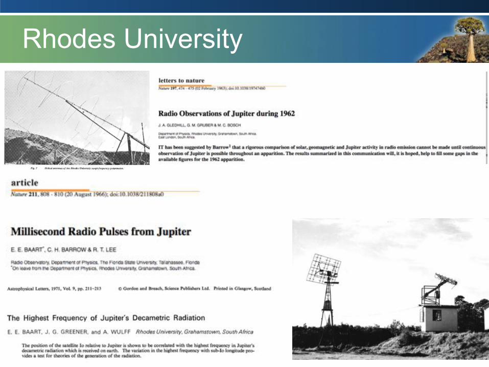
Rhodes University
2
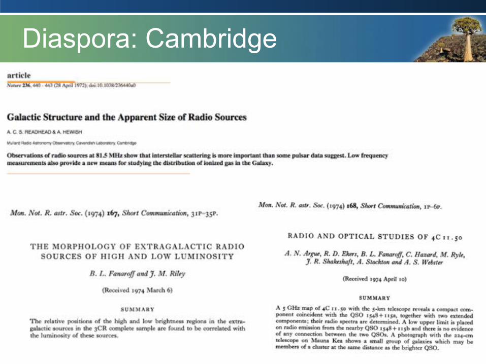
Diaspora: Cambridge
3

Diaspora: Jodrell Bank
4
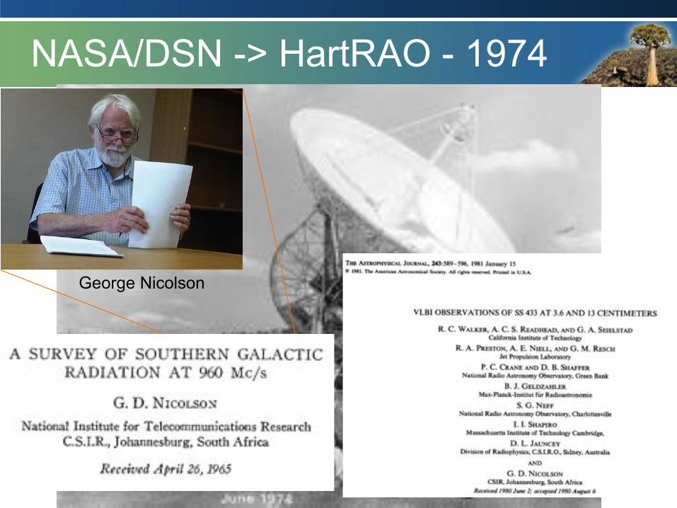
NASA/DSN -> HartRAO - 1974
5
George Nicolson
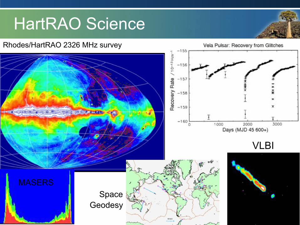
Rhodes/HartRAO 2326 MHz survey
HartRAO Science
VLBI
MASERS Space
Geodesy
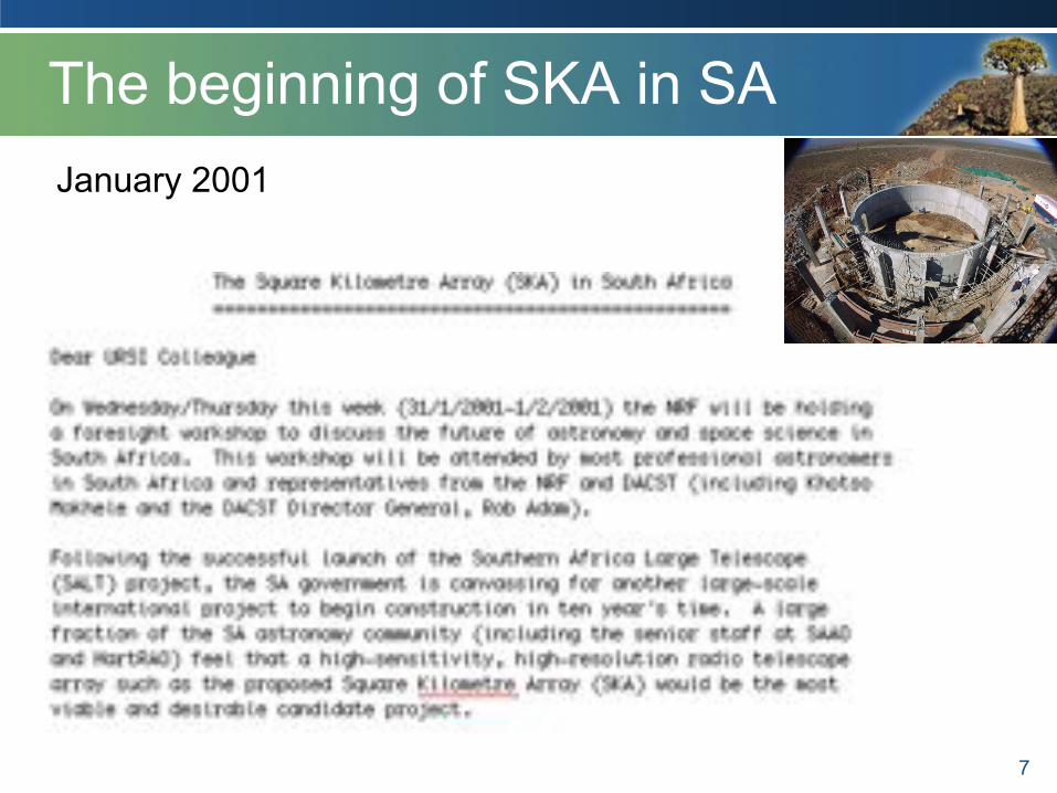
The beginning of SKA in SA
7
January 2001
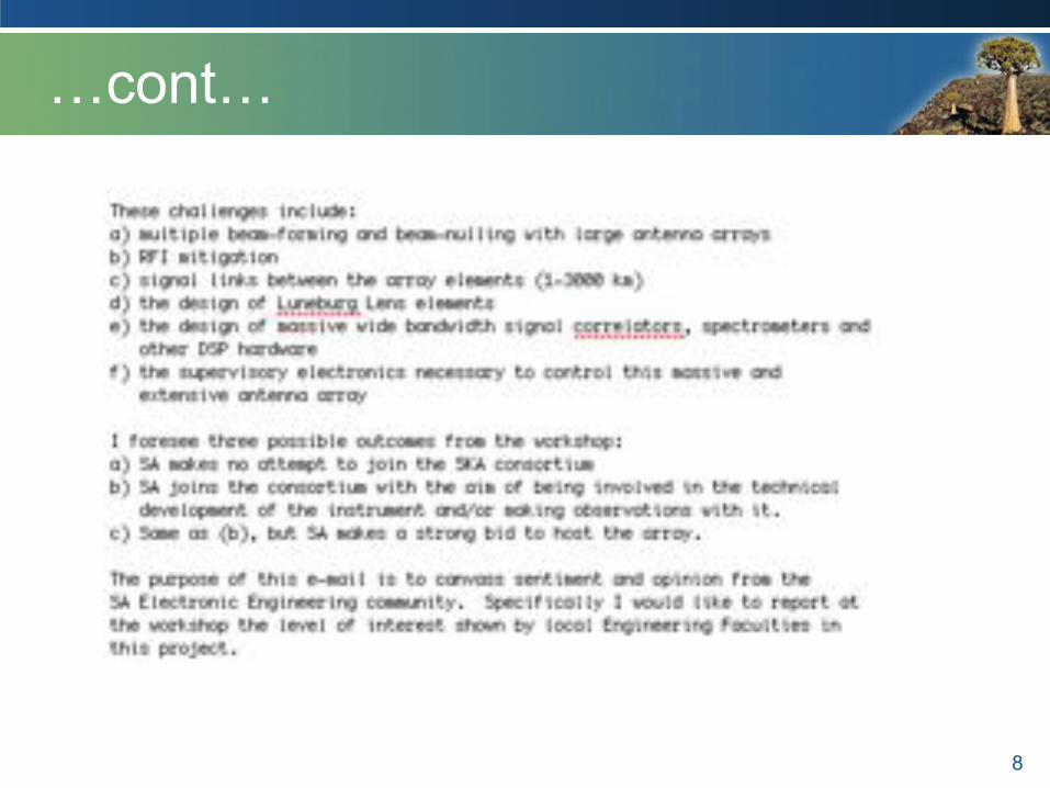
…cont…
8
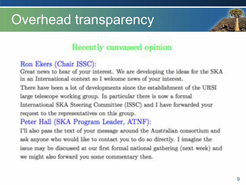
Overhead transparency
9

Berkeley ISSC: July 2001
10 ISSC 11 – Cape Town 2004

Ron invited to SAIP (Sept 2002)
11
Khotso Mokhele
Adi Paterson Rob Adam
• 12
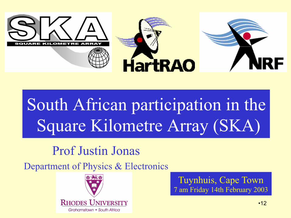
South African participation in the Square Kilometre Array (SKA)
Prof Justin Jonas Department of Physics & Electronics
Tuynhuis, Cape Town 7 am Friday 14th February 2003

• 13
POSSIBLE SITES
1
2
3 4
5
14
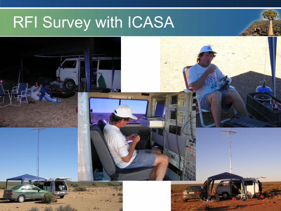
RFI Survey with ICASA

Let’s put it here…
15

Over there Bernie …

Population Density (and RFI)
17
Northern Cape 4% population 40% land area
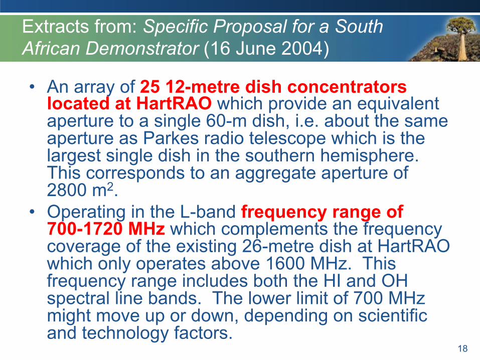
Extracts from: Specific Proposal for a South African Demonstrator (16 June 2004)
• An array of 25 12-metre dish concentrators located at HartRAO which provide an equivalent aperture to a single 60-m dish, i.e. about the same aperture as Parkes radio telescope which is the largest single dish in the southern hemisphere. This corresponds to an aggregate aperture of 2800 m2.
• Operating in the L-band frequency range of 700-1720 MHz which complements the frequency coverage of the existing 26-metre dish at HartRAO which only operates above 1600 MHz. This frequency range includes both the HI and OH spectral line bands. The lower limit of 700 MHz might move up or down, depending on scientific and technology factors.
18

…cont... • The focal plane arrays used with these dishes would
be based on the technologies developed in SKADS DS4 and DS5. DS5 (i.e. EMBRACE) tiles would not be suitable because of their single polarization capability and 100 K noise temperature. DS4 outputs are expected to be suitable.
• An 8x8 element focal plane array might be adequate, but 12x12 is likely to be the maximum required. This would be roughly 1-m2 of SKADS patch. The use of a concentrator therefore gives a multiplier effect of about 100. Field of View (FoV) would probably be about 5-deg (1150 FoVs per hemisphere).
• A maximum baseline of 1 km to match science and physical layout of HartRAO valley, but it is likely that the array would be more compact that this (baselines of about 100 m).
19
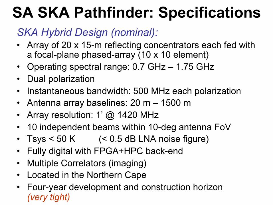
SA SKA Pathfinder: Specifications SKA Hybrid Design (nominal): • Array of 20 x 15-m reflecting concentrators each fed with
a focal-plane phased-array (10 x 10 element) • Operating spectral range: 0.7 GHz – 1.75 GHz • Dual polarization • Instantaneous bandwidth: 500 MHz each polarization • Antenna array baselines: 20 m – 1500 m • Array resolution: 1’ @ 1420 MHz • 10 independent beams within 10-deg antenna FoV • Tsys < 50 K (< 0.5 dB LNA noise figure) • Fully digital with FPGA+HPC back-end • Multiple Correlators (imaging) • Located in the Northern Cape • Four-year development and construction horizon
(very tight)
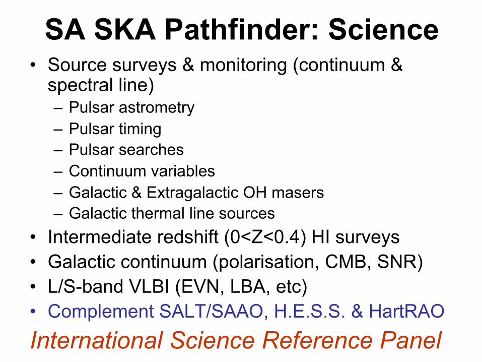
SA SKA Pathfinder: Science • Source surveys & monitoring (continuum &
spectral line) – Pulsar astrometry – Pulsar timing – Pulsar searches – Continuum variables – Galactic & Extragalactic OH masers – Galactic thermal line sources
• Intermediate redshift (0<Z<0.4) HI surveys • Galactic continuum (polarisation, CMB, SNR) • L/S-band VLBI (EVN, LBA, etc) • Complement SALT/SAAO, H.E.S.S. & HartRAO International Science Reference Panel
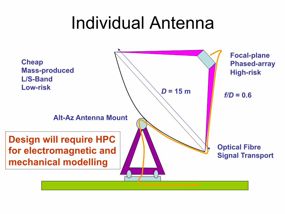
Individual Antenna
D = 15 m f/D = 0.6
Focal-plane Phased-array High-risk
Optical Fibre Signal Transport
Alt-Az Antenna Mount
Cheap Mass-produced L/S-Band Low-risk
Design will require HPC for electromagnetic and mechanical modelling
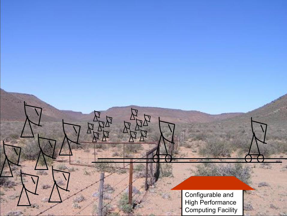
Configurable and High Performance Computing Facility
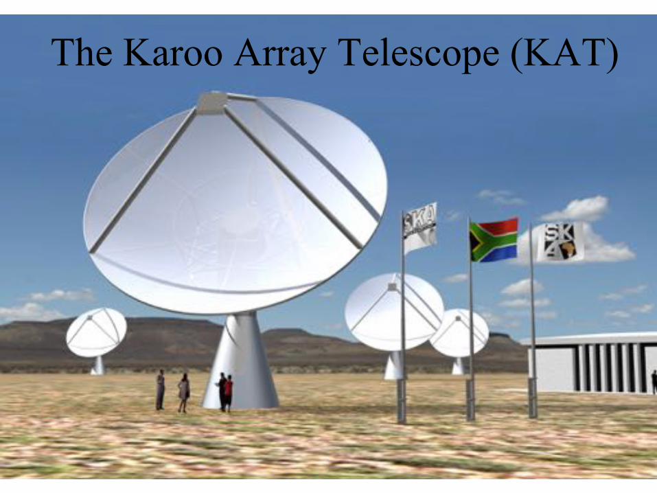
The Karoo Array Telescope (KAT)
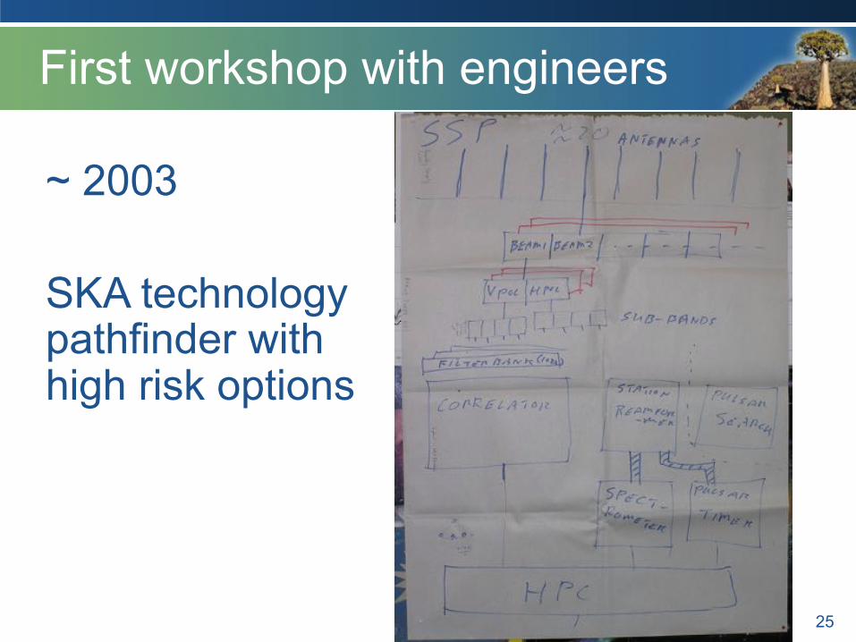
First workshop with engineers
25
~ 2003 SKA technology pathfinder with high risk options
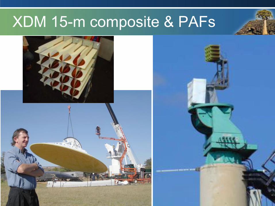
XDM 15-m composite & PAFs
26

XDM 15-m
27
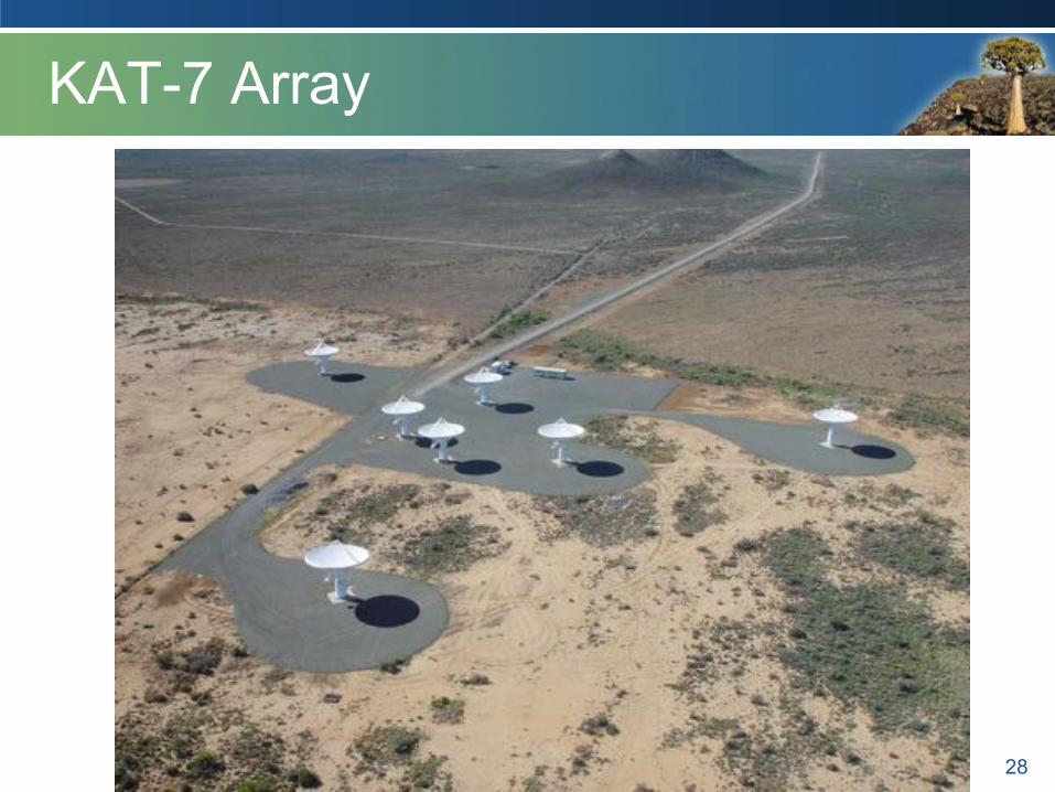
KAT-7 Array
28
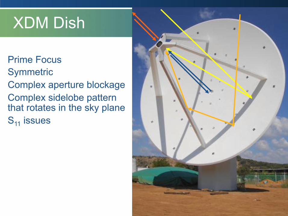
XDM Dish
Prime Focus Symmetric Complex aperture blockage Complex sidelobe pattern that rotates in the sky plane S11 issues

Offset Gregorian Optics
Unblocked aperture Clean beam pattern Polarization purity S11 good
12 m
15 m
Rx
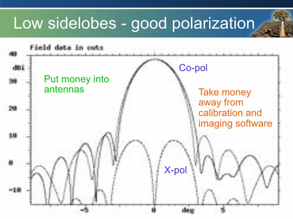
Low sidelobes - good polarization
Co-pol
X-pol
Put money into antennas Take money
away from calibration and imaging software
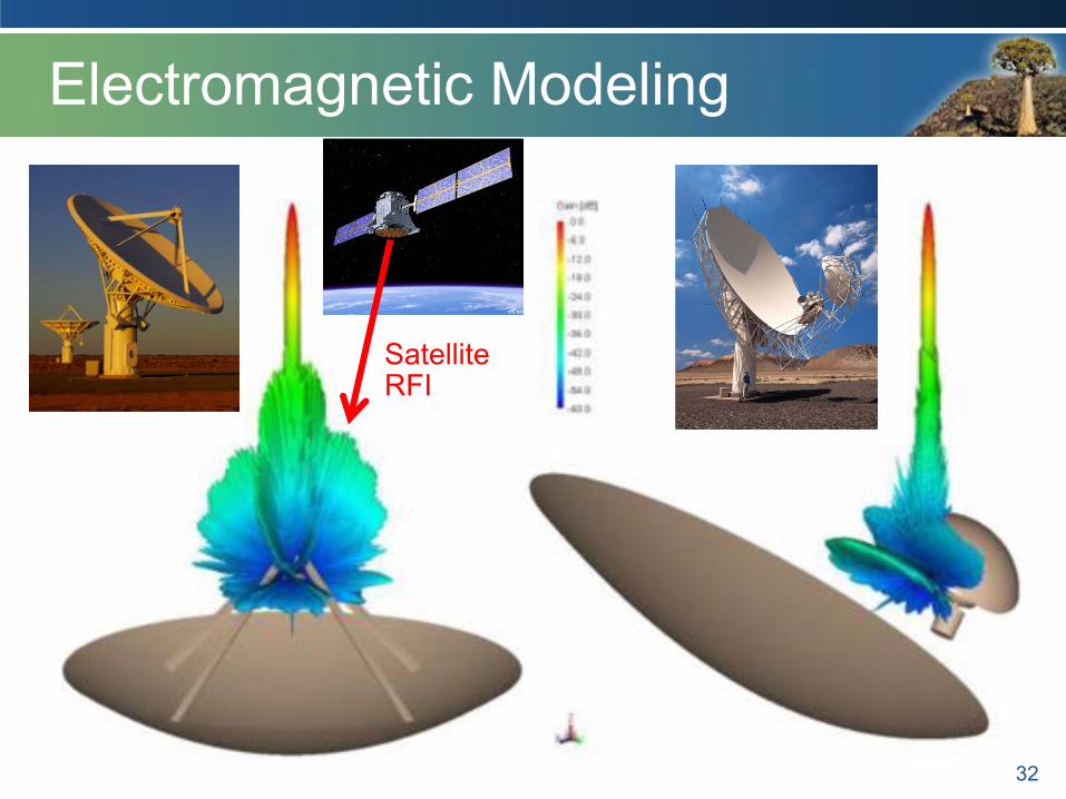
Electromagnetic Modeling
32
Satellite RFI
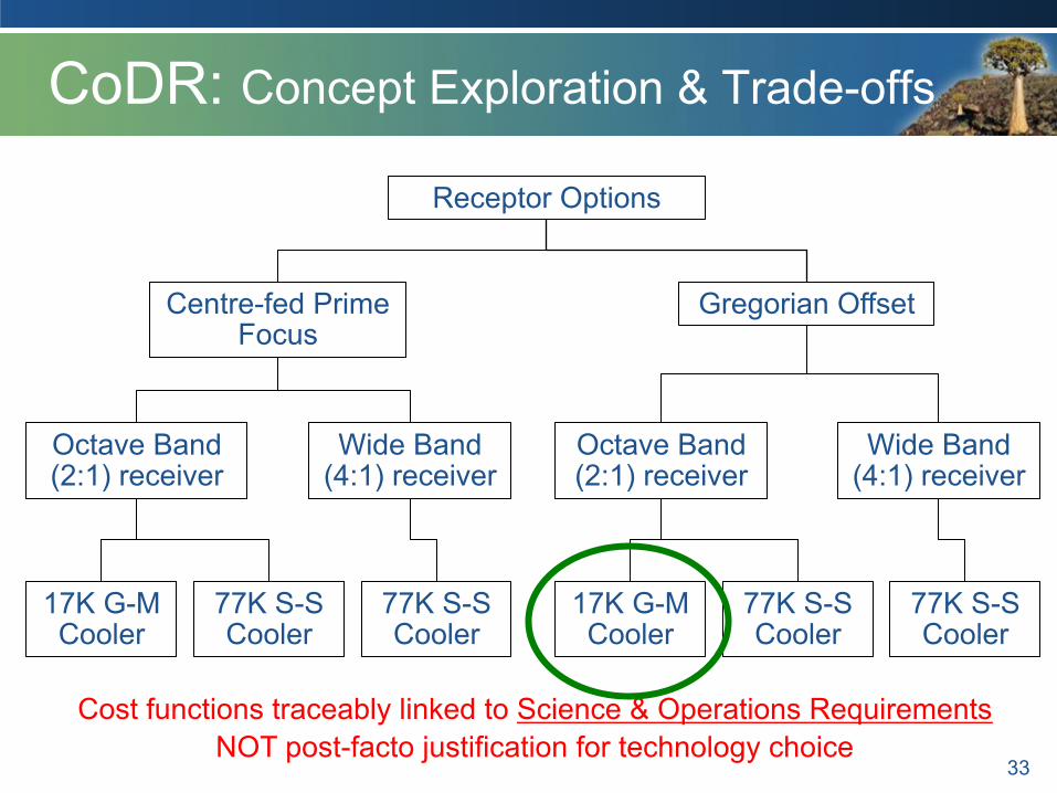
CoDR: Concept Exploration & Trade-offs
33
Receptor Options
Centre-fed Prime Focus
Gregorian Offset
Octave Band (2:1) receiver
Wide Band (4:1) receiver
Wide Band (4:1) receiver
Octave Band (2:1) receiver
17K G-M Cooler
17K G-M Cooler
77K S-S Cooler
77K S-S Cooler
77K S-S Cooler
77K S-S Cooler
Cost functions traceably linked to Science & Operations Requirements NOT post-facto justification for technology choice
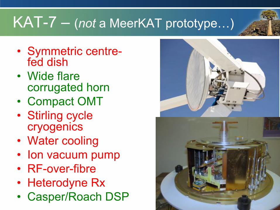
KAT-7 – (not a MeerKAT prototype…)
• Symmetric centre-fed dish
• Wide flare corrugated horn
• Compact OMT • Stirling cycle
cryogenics • Water cooling • Ion vacuum pump • RF-over-fibre • Heterodyne Rx • Casper/Roach DSP
34
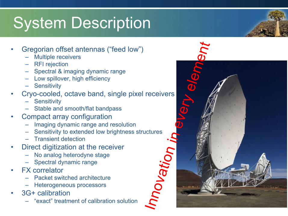
System Description • Gregorian offset antennas (“feed low”)
– Multiple receivers – RFI rejection – Spectral & imaging dynamic range – Low spillover, high efficiency – Sensitivity
• Cryo-cooled, octave band, single pixel receivers – Sensitivity – Stable and smooth/flat bandpass
• Compact array configuration – Imaging dynamic range and resolution – Sensitivity to extended low brightness structures – Transient detection
• Direct digitization at the receiver – No analog heterodyne stage – Spectral dynamic range
• FX correlator – Packet switched architecture – Heterogeneous processors
• 3G+ calibration – “exact” treatment of calibration solution In
nova
tion
in e
very
ele
men
t
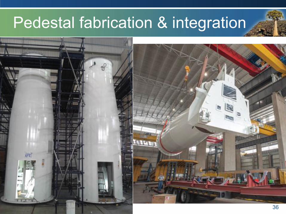
Pedestal fabrication & integration
36
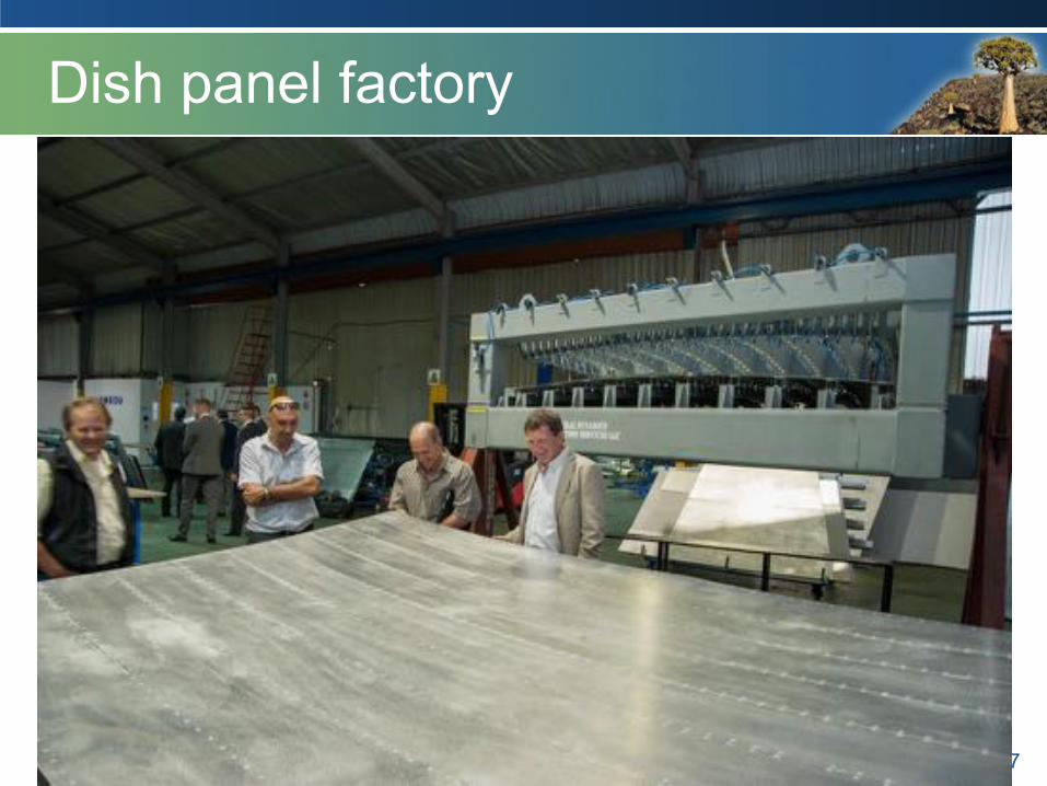
Dish panel factory
37

Carbon-fibre Subreflector
38

Off and on-site production line
39

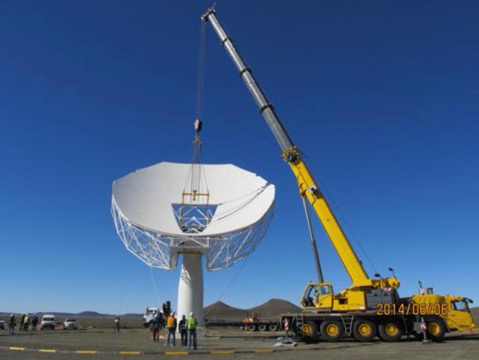
Completed main reflector
40
41
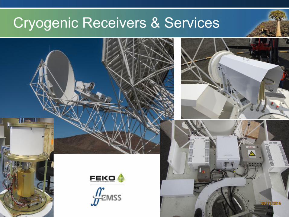
Cryogenic Receivers & Services
42

Big Data
43
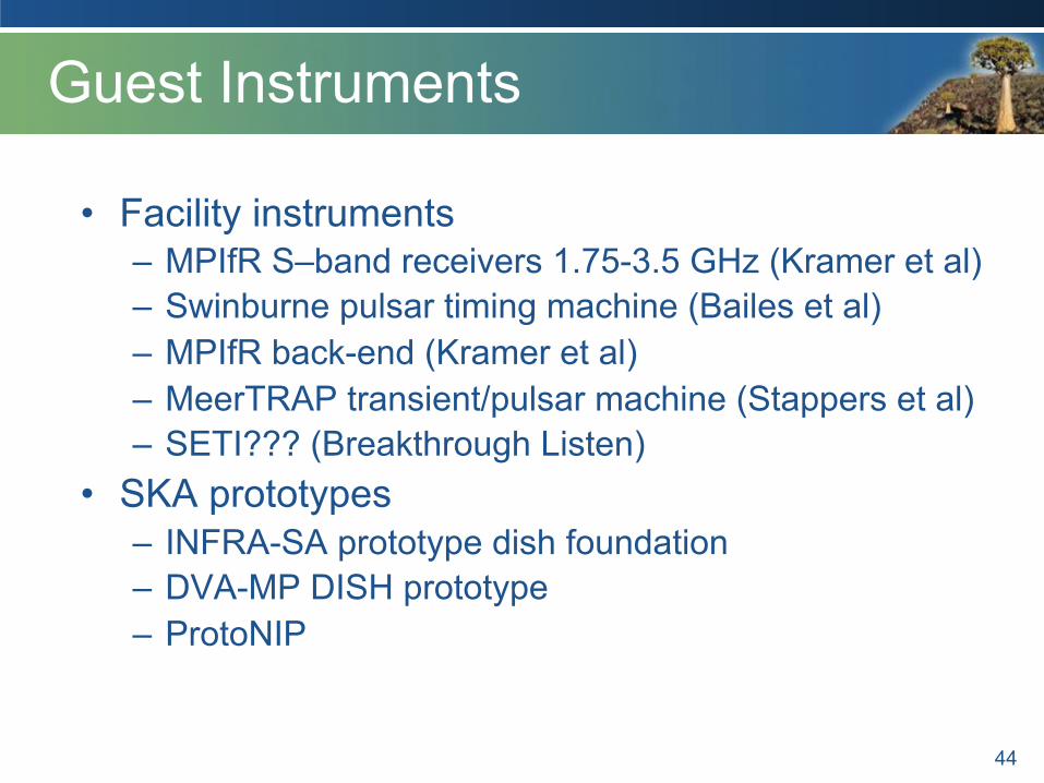
Guest Instruments
• Facility instruments – MPIfR S–band receivers 1.75-3.5 GHz (Kramer et al) – Swinburne pulsar timing machine (Bailes et al) – MPIfR back-end (Kramer et al) – MeerTRAP transient/pulsar machine (Stappers et al) – SETI??? (Breakthrough Listen)
• SKA prototypes – INFRA-SA prototype dish foundation – DVA-MP DISH prototype – ProtoNIP
44
45
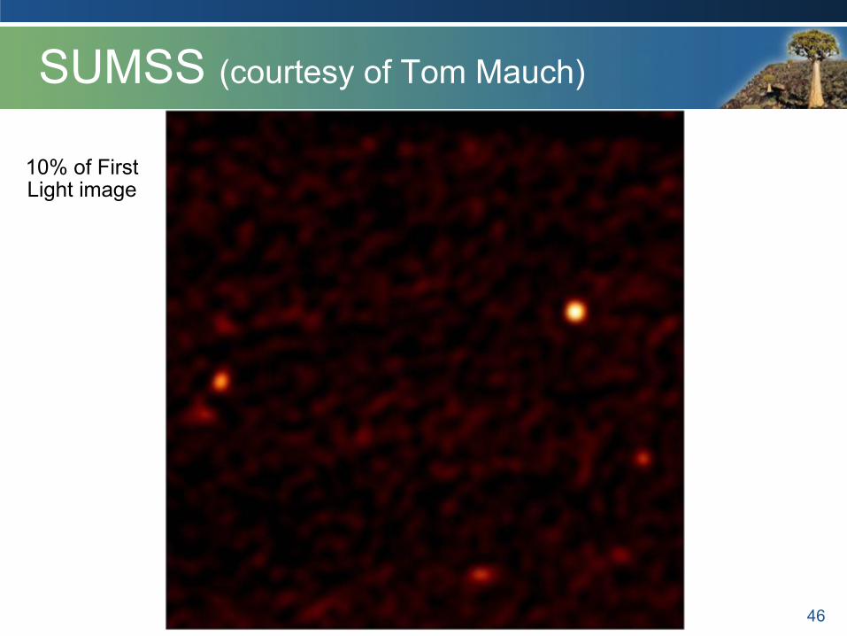
SUMSS (courtesy of Tom Mauch)
46
10% of First Light image
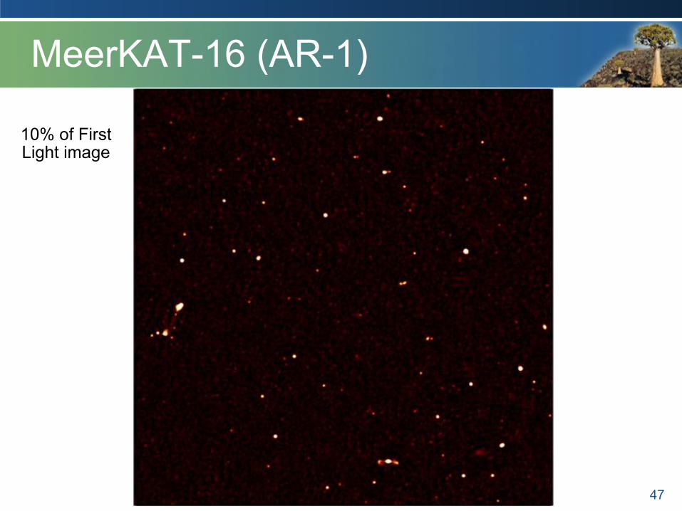
MeerKAT-16 (AR-1)
47
10% of First Light image
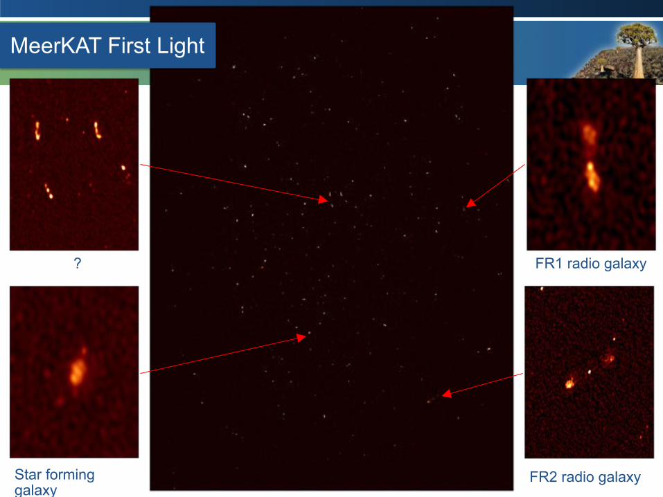
MeerKAT First Light
FR1 radio galaxy
FR2 radio galaxy Star forming galaxy
?