missouri weatherization assistance program technical manual · missouri . weatherization assistance...
TRANSCRIPT

i October 2016
Missouri Weatherization Assistance Program
Technical Manual
Technical Guidelines and Best Practice For Missouri WAP Subgrantees

ii October 2016
Table of Contents ...........................................................................................................Page Overview ...............................................................................................................................1 I. How to Use the Technical Manual .................................................................................1 II. Health and Safety .............................................................................................................3 A. Worker Safety ............................................................................................................4 1. General Guidelines...............................................................................................4 2. Subgrantee Health and Safety Policy ...................................................................5 3. Subgrantee First Aid Program .............................................................................6 4. Subgrantee Personal Protection Program.............................................................6 5. Subgrantee Tool Safety Program .........................................................................7 6. Subgrantee Fire Protection Program ....................................................................8 7. Subgrantee Job Hazards and Chemical Safety Identification Program ...............9 8. Material Safety Data Sheet Catalog .....................................................................10 9. OSHA Confined Space Requirements…………………………………………..10 B. Building/Occupant Safety ..........................................................................................11 1. Carbon Monoxide (CO) .......................................................................................11 2. Combustion Safety Alarms ..................................................................................12 3. Combustion Systems ............................................................................................12 4. Response to Combustion Appliance Problems ....................................................15 5. Emergency Situations: Immediate Follow-up Required ......................................15 6. Non-Emergency: One-day Follow-up Required ..................................................16 7. Non-Emergency: Five-day Follow-up Required .................................................16
8. Blower Door Safety .............................................................................................17 9. Moisture ...............................................................................................................18 10. Hazardous Conditions & Materials ......................................................................20 11. Electrical Safety ...................................................................................................23 12. Lead-safe Weatherization ....................................................................................24 13. Mercury ................................................................................................................26 14. Pest Infestation ....................................................................................................26 15. Additional Safety .................................................................................................27 C. Mechanical Ventilation/ASHRAE 62.2 Standards ....................................................27 1. General Guidelines...............................................................................................28 2. Inspection of Existing Ventilation .......................................................................30 3. Required Ventilation Determination ....................................................................32 4. Retrofit of Existing Ventilation ...........................................................................34 5. Installation and Replacement of Ventilation ........................................................34 6. Inspection of Installed Ventilation .......................................................................36 D. Required Minimum Subgrantee Deferral Policy .......................................................36 1. Required Minimum Deferral Policy ....................................................................37 2. Documentation .....................................................................................................39

iii October 2016
III. Mechanical Systems & Combustion Appliances .............................................................41 A. Primary and Secondary Heating and Cooling Systems ……………………….........41
1. Primary Heating and Cooling Systems…………………………………………..41 2. Secondary Heating and Cooling Systems……………………………………….42
B. Combustion Heating Systems ....................................................................................43 1. Natural Gas and Propane Systems .......................................................................43 2. Oil Systems ..........................................................................................................49 3. Wood-Solid Fuel Systems....................................................................................50 C. Combustion Appliance Zone (CAZ) and Carbon Monoxide Testing ........................50 1. Measuring Base Pressure .....................................................................................51 2. Establishing Worst Case ......................................................................................51 3. Measuring Spillage and CO Under Worst Case Conditions ................................52 4. Measuring Spillage and CO Under Natural Conditions ......................................52 5. Ambient CO .........................................................................................................53
6. Daily Combustion Appliance Zone (CAZ) Test ..................................................53 D. Combustion Air Supply .............................................................................................54 1. Atmospheric Combustion Appliances .................................................................54 2. Direct Vent and Combustion Air .........................................................................54 E. Heating System Repair and Replacement ..................................................................55 1. General Information .............................................................................................55 2. Emergency Services .............................................................................................58 F. Heating System Modifications ...................................................................................58 G. Space Heaters .............................................................................................................58 1. Vented Space Heaters ..........................................................................................58 2. Unvented Space Heaters ......................................................................................59 H. Mobile Home Systems ...............................................................................................60 1. General Characteristics ........................................................................................61 2. System Repair or Replacement ............................................................................61 I. Gas Ranges and Ovens...............................................................................................62 1. Natural Gas or Propane Stove-top Burner Testing ..............................................62 2. Natural Gas or Propane Oven Testing Instructions and Action Levels ...............63 J. Dryers ........................................................................................................................63 1. General Requirements ..........................................................................................63 2. Dryer Venting Requirements ................................................................................63 K. Water Heaters.............................................................................................................64 1. General Requirements ...........................................................................................64 2. Water Heater Repairs ............................................................................................64 3. Water Heater Replacement ...................................................................................65 4. Water Heater Insulation General Requirements and temperature settings ..........65 5. Gas-Fired Water Heater Insulation ......................................................................66 6. Electric Water Heater Insulation ..........................................................................66 7. Water Heater Blankets .........................................................................................67 8. Water Heater Pipe Insulation ...............................................................................67 L. Air Conditioners and Heat Pumps .............................................................................68
1. Air Conditioner and Heat Pump Repair ...............................................................68 2. Air Conditioner and Heat Pump Replacement as an ECM ..................................69
iv October 2016
3. Air Conditioner and Heat Pump: Health and Safety Replacement/Installation ...71 IV. Shell & Duct Air Leakage Diagnostics ............................................................................75 A. Blower Door Testing & Diagnostics..........................................................................75 1. Preparation for Blower Door Test ........................................................................75 2. Blower Door Depressurization Test (preferred) ..................................................77 3. Blower Door Pressurization Test .........................................................................78 B. Blower Door Guided Air Sealing ..............................................................................78 1. Pre-Guideline and Guideline Air Sealing ............................................................78 C. Air Sealing Cost-Effective Guidelines.......................................................................79 1. Procedure .............................................................................................................79 D. Target Infiltration Reduction .....................................................................................79 E. Air Handler Pressure Testing .....................................................................................80
1. Air Handler Dominant Duct Leakage Testing .....................................................80 2. Air Handler Pressure Balance Testing .................................................................81
F. Duct Leakage Testing ................................................................................................81 1. General Information .............................................................................................81 2. Duct Leakage Standards ......................................................................................82 3. Pressure Pan Testing Procedures .........................................................................83 4. Duct Blower Testing for Leakage to Outdoors ....................................................85 G. Pressure Testing Air Barriers .....................................................................................86 1. General Information .............................................................................................86 2. Primary versus Secondary Air Barriers ...............................................................86 3. Simple Attic Leak Testing ...................................................................................87 4. Zonal Pressure Testing .........................................................................................88 5. Interpreting Zone Pressure ...................................................................................89 V. Air Sealing .......................................................................................................................91 A. Air Sealing Requirements ..........................................................................................91 1. Air Sealing Guidelines .........................................................................................91 2. Penetrations and Holes .........................................................................................93 3. Fireplace Plugs and Equipment Covers ...............................................................94
B. Ducted Distribution Requirements ............................................................................94 1. Ductwork Inspection, Cleaning and Sealing ........................................................94 C. Window and Doors ....................................................................................................95 1. Primary Windows ................................................................................................96 2. Window Air Leakage ...........................................................................................96 3. Window Repairs...................................................................................................97 4. Window Replacements ........................................................................................98 5. Storm Windows ...................................................................................................99 6. Non-Allowable Window Materials ......................................................................100 7. Doors ....................................................................................................................100 8. Door Air Leakage ................................................................................................100 9. Door Repairs ........................................................................................................100 10. Door Replacements ..............................................................................................101 11. Storm Doors .........................................................................................................102

v October 2016
VI. Insulation .......................................................................................................................105 A. Attic Insulation...........................................................................................................105 1. General Procedures ..............................................................................................105 2. Moisture Inspection and Repair ...........................................................................106 3. Electrical Safeguards ...........................................................................................107 4. Treatment of Other Hazards .................................................................................108 5. Attic Access .........................................................................................................108 6. Insulation Shielding and Blocking .......................................................................109 B. Installation Methods for Attic Insulation ...................................................................110 1. General Procedures ..............................................................................................110 2. Insulation Coverage and Density .........................................................................111 3. Enclosed Ceiling Cavities ....................................................................................112 4. Storage Space .......................................................................................................112 5. Ductwork Insulation.............................................................................................112 6. Drill-and-Blow Patching ......................................................................................113 C. Attic Ventilation.........................................................................................................113 1. General Installation ..............................................................................................113 2. Soffit Vents ..........................................................................................................114 3. High-Low Vents...................................................................................................114 4. Gable Vents ..........................................................................................................114 5. Knee Wall Ventilation .........................................................................................114 D. Sidewall Insulation.....................................................................................................114 1. General Procedures ..............................................................................................114 2. Moisture Inspection and Repair ...........................................................................116 3. Treatment of Other Hazards .................................................................................116 4. Interior Inspection and Repairs ............................................................................116 5. Exterior Inspection and Repairs ...........................................................................117 E. Installation Methods for Wall Insulation ...................................................................118 1. General Procedures ..............................................................................................118 2. Blocking ...............................................................................................................118 3. Materials ..............................................................................................................118 4. Insulation Coverage, Density and Voids .............................................................119 5. Plugs and Patching ...............................................................................................119 6. Brick Siding .........................................................................................................120 7. Quality Control ....................................................................................................120 F. Foundation Insulation ................................................................................................120 1. General Procedures ..............................................................................................120 2. Moisture Inspection and Repair ...........................................................................121 3. Wall Moisture Barrier ..........................................................................................122 4. Treatment of Other Hazards .................................................................................122 5. Defining the Thermal Boundary ..........................................................................122 G. Foundation Insulation Installation Methods ..............................................................123 1. Storage Space .......................................................................................................123 2. Materials ..............................................................................................................123 3. Crawl Space Insulation ........................................................................................125

vi October 2016
H. Floor Insulation ..........................................................................................................126 1. General Procedures ..............................................................................................126 2. Moisture Inspection and Repairs .........................................................................126 3. Defining the Thermal Boundary ..........................................................................126 I. Installation Methods for Floor Insulation ..................................................................127 1. General Procedures ..............................................................................................127 2. Materials ..............................................................................................................128 3. Insulation Coverage Procedures ..........................................................................128 4. Storage Space .......................................................................................................128 5. Ducts and Pipes Procedures .................................................................................129 6. Crawl Space Ventilation ......................................................................................129 VII. Baseload .....................................................................................................................131 A. Energy-Saving Showerheads and Faucet Aerators ....................................................131 B. Plug Load ...................................................................................................................131 1. Refrigerators/Freezers ..........................................................................................131 2. Lighting Replacement ..........................................................................................132 VIII. Mobile Home Requirements ......................................................................................135 A. Inspections and Repairs .............................................................................................135 1. General Information .............................................................................................135 2. Moisture Problems ...............................................................................................135 3. Electrical Inspections ...........................................................................................135 B. Air Leakage Reduction Requirements .......................................................................136 1. General Requirements ..........................................................................................136 C. Insulation....................................................................................................................137 1. General Information .............................................................................................137 2. Ceiling Insulation .................................................................................................137 D. Ductwork....................................................................................................................138 1. General Requirements ..........................................................................................138 2. Mobile Home Belly Return Air Systems .............................................................138 3. Duct Repair and Treatment ..................................................................................138 E. Floor (Belly) Insulation..............................................................................................139 1. Floor Insulation Requirements .............................................................................139 F. Sidewall Insulation.....................................................................................................141 1. General Requirements ..........................................................................................141 G. Water Heater Closets .................................................................................................142 1. General Information .............................................................................................142 IX. Multi-Family Building ....................................................................................................145 A. General Requirements/Information ...........................................................................145 1. Eligibility .............................................................................................................145 2. Prior Approval .....................................................................................................145 3. Expenditures/Funding Issues ...............................................................................145 4. Building Measures ...............................................................................................146 B. Tasks and Analysis for Preparing the Report ............................................................146 1. Energy Consumption and Facility Data ...............................................................146
vii October 2016
2. Inventory Existing Systems and Equipment ........................................................147 3. Inventory Data .....................................................................................................147 4. Diagnostics ...........................................................................................................148 X. Initial Audits and Final Inspections ..................................................................................149 A. Initial Audit and Final Inspection Requirements ......................................................149 1. Subgrantee Requirements ....................................................................................149 B. Initial Audit ...............................................................................................................149 1. General Requirements .........................................................................................149 2. Initial Audit Procedures .......................................................................................149 C. Final Inspection/Quality Control ..............................................................................151 1. General Requirements ..........................................................................................151
2. DED/DE Criteria to Pass Housing Inspection .....................................................152 XI. Computerized Audits .......................................................................................................155 A. Computerized Audit Software Selection ...................................................................155 1. Software Version ................................................................................................155 2. NEAT ...................................................................................................................155 3. MHEA ..................................................................................................................155 B. Weatherization Assistant Setup Library ....................................................................155 1. Key Parameters Tab .............................................................................................155 2. Fuel Costs Tab .....................................................................................................156 3. Library Measures Tab ..........................................................................................156 C. Performing a Computerized Audit on a Home ..........................................................159 1. General Information for Tabs in NEAT/MHEA .................................................159 2. Audit Information Tab .........................................................................................160 3. Shell Tab ..............................................................................................................160 4. Heating Tab .........................................................................................................162 5. Cooling Tab .........................................................................................................164 6. Ducts/Infiltration Tab...........................................................................................165 7. Baseload Tab ........................................................................................................166 8. Itemized Cost Tab ................................................................................................167 D. Computerized Energy Audit Requirements ...............................................................168 1. General Requirements ..........................................................................................168 2. Savings to Investment Ratio (SIR) .....................................................................168 3. Cumulative SIR ....................................................................................................169 4. Client File Documentation ...................................................................................169 XII. Miscellaneous .................................................................................................................171
A. Prioritization of Weatherization Measures ................................................................171 B. Work Order Review with Client ................................................................................172 C. Client Refusal of Material Installation .......................................................................172 D. Incidental Repairs ......................................................................................................172 E. Low Cost/No Cost Activities .....................................................................................174 F. Material Standards .....................................................................................................174
viii October 2016
XIII. Section 106 Requirements ............................................................................................177 A. Programmatic Agreement Implementation ................................................................177 1. Training ................................................................................................................177 2. Client File Requirements .....................................................................................177 3. Energy Audit Procedures .....................................................................................178 4. Emergency Situation Undertakings .....................................................................178 B. Undertakings That Require Further Review ..............................................................178 C. Undertakings Exempt from Further Review ..............................................................179 1. Categorical Exemptions .........................................................................................179 D. Section106 Compliance under Extraordinary Circumstances ...................................181
Glossary ..........................................................................................................................185 Attachments: Attachment 1.1 .................DOE WPN 08-4 Space Heater Policy Attachment 1.2 .................DOE WPN 11-6 Health and Safety Guidance Attachment 1.3 .................DOE WPN 11-6a Supplemental Health and Safety Guidance Attachment 1.4 .................DOE WPN 12-9 Incidental Repair Measure Guidance Attachment 2.1 ................Quality Control Inspection Form Attachment 2.2 ................Client Interview & Auditor Assessment Form Attachment 2.3 ................Combustion Appliance Spillage Test Form Attachment 2.4 ................Diagnostic Field Form Attachment 2.5 ................Mechanical Systems Audit Form Attachment 2.6 ................Baseload Replacement Audit Form Attachment 2.7 .................Incidental Repair Justification Form Attachment 2.8 .................ASHRAE 62.2 Form
Attachment 2.9 .................Daily Combustion Appliance Zone (CAZ) Test Form Attachment 3.1 .................Depressurization Blower Door Procedures
Attachment 3.2 .................Mechanical Systems Audit Procedures Attachment 3.3 .................Final Inspection Procedures Attachment 3.4 .................CAZ Pressure Diagnostics Attachment 3.5 .................Zonal Pressure Diagnostics-Add a Hole Method Attachment 3.6 .................ASHRAE Client Education Form Attachment 3.7 .................Window Leakiness Guidelines Attachment 3.8 .................Energy Star Equipment Specifications
Attachment 4.1 .................MoWAP Interface for the Weatherization Assistant Work Orders Attachment 4.2 ................MoWAP Annual Energy Savings Worksheet Calculations Attachment 4.3 .................Fuel Cost Update Information Attachment 5.1 ................DED Multi-Family Submittal Information Requirements Attachment 6.1 ................DED/DE - SHPO Section 106 Interagency Agreement Attachment 6.2 ................Section 106 Photos Do’s & Don’ts Attachment 6.3 ................Measures Exempt From Further Review Attachment 6.4 ................Section 106 Project Information Form

1 October 2015
Overview
The Technical Standards and Best Practices included in this manual have been developed by Missouri Department of Economic Development Division of Energy (DED/DE) staff to provide Missouri Subgrantees with technical guidance on effective and allowable weatherization practices. This guidance was designed to assist subgrantees in their efforts to reduce energy waste, improve the comfort and durability of homes, and to enhance the health and safety of the occupants as well as the subgrantee staff and contractors working in those homes. Following these standards and best practices will allow subgrantees to remain in compliance with United States Department of Energy (DOE) and DED/DE regulations.
Section I: How to use the Technical Manual
This version of the technical manual has been aligned to the National Standard Work Specifications (SWS). The SWS were developed for DOE by the National Renewable Energy Lab (NREL) to better insure that work performed in homes is effective, durable, and safe. The entire SWS can be accessed directly at https://sws.nrel.gov/. This edition has extensive written updates aligning DED/DE requirements to the national standards. In addition, the inclusion of SWS detail level numbering throughout this edition will allow for easier cross-referencing with the SWS web site. The SWS references are given throughout in following formatting style:
Detail Number Detail Name
SWS Detail: 2.0100.1 Global Worker Safety
The numbering of the Technical Manual follows the following formatting style: I. Section
A. Subsection 1. Topic
a. Subtopic (1) Detail
(a) Part
A. Important Definitions • Energy Conservation Measure (ECM): Weatherization measures that are evaluated by the
computerized audit that have a SIR of 1.0 or greater.
• Health and Safety Measure: Actions necessary to maintain the physical well-being of either occupants and/or weatherization workers where: o Costs are reasonable as determined by DOE in accordance with the Grantee's approved
Grantee plan; AND o The actions must be taken to effectively perform weatherization work; OR o The actions are necessary as a result of weatherization work.

2 October 2016
• Incidental Repair: Incidental repairs are minor repairs necessary for the effective performance or preservation of energy conservation measures (ECM). All work associated with completing the installation of an ECM so that it will comply with code, the SWS or DE standards must be included in the cost of the measure. Minor repairs necessary to install an ECM or work which is necessary to protect or preserve an ECM once installed, may be considered an incidental repair. Refer to the Technical Manual, Section XII, Subsection D for additional information.
• Savings to Investment Ratio (SIR): The life cycle savings of an energy improvement divided by the initial investment, as calculated by the computerized audit. Within the Weatherization Assistance Program, energy conservation measures must have a SIR of 1.0 or greater in order to be eligible for installation.
• Standard Work Specifications (SWS): The Department of Energy has directed the usage of
the Standard Work Specifications (SWS) developed by the National Renewable Energy Laboratory as a means to achieve uniform weatherization standards nationwide. The specifications reflect the minimum requirements necessary to ensure that work performed during weatherization is effective, durable and safe.
THE REMAINDER OFTHIS PAGE IS INTENTIONALLY LEFT BLANK FOR FUTURE EXPANSION
3 October 2016
Section II: Health and Safety Health and safety issues have become an important part of the Weatherization Assistance Program (WAP) as knowledge about the hazards within dwellings has increased since the Program's inception. When a health or safety hazard is detected, it is the policy of the Department of Economic Developments' Division of Energy (DED/DE), administrator of the Missouri Weatherization Assistance Program, to address the hazard. This policy is tempered by recognition that the primary goal of the WAP is energy conservation and that funds should focus on that goal. Although balance is needed between these competing issues, the health and safety of the building, occupants and weatherization crews or contractors shall not be compromised by any retrofit material, technique or practice.
According to 10 CFR Part 440, allowable energy related health and safety actions are those actions necessary to maintain the physical well-being of both the occupants and/or weatherization workers where:
• Costs are reasonable as determined by DOE in accordance with the Grantee’s approved
Grantee Plan; AND • The actions must be taken to effectively perform weatherization work; OR • the actions are
necessary as a result of weatherization work.
A subgrantee must ask themselves two questions: • What must we do within reasonable costs to get the home to a point we can go forward with
weatherizing, where the weatherization work will be lasting and effective? • What must we do to ensure that the weatherization work we conducted does not create a
health or safety problem for the occupant?
Code corrections are allowable health and safety costs when they are required by the local Code Authority in order for weatherization work to be performed. You must note the specific code requirement with reference to the efficiency measure(s) that triggered the code activity. If the code correction cannot be related to weatherization work, then WAP funds cannot be used to make the code correction. An example of this would be bringing hand rails up to code. Since it is not related to the installation of the efficiency measures, it would not be an allowable cost. When health and safety costs are not reasonable or beyond the subgrantees budget, the home may need to be deferred.
Subgrantees may not provide only health and safety measures on a home without conducting other cost effective weatherization measures. For example; a subgrantee is not allowed to only install a smoke detector or carbon monoxide detector as a health and safety measure, without energy conservation measures (ECM), such as insulation or air sealing.
The following sections establish areas of concern that may affect the health and safety of the workers and the clients. In most cases, the best approach to limiting the health and safety risk is to minimize their exposure to the hazard. The inability to minimize exposure may result in some or all of the work being stopped on any particular dwelling.
4 October 2016
A. Worker Safety A subgrantee is responsible for complying with Occupational Safety and Health Administration (OSHA) requirements in all weatherization activities that involve staff personnel. When contractors are employed by subgrantees, those contractors also are required to comply with OSHA. For detailed information on worker health and safety, refer to Construction Industry OSHA Safety and Health Standards (29 CFR 1926). The DED/DE expectation is for crews, contractors and auditors to be able to work under conditions that do not jeopardize their own health and safety. The office, warehouse and other workspace owned or rented by each subgrantee should be a safe and healthy environment. The contractor cost to comply with OSHA, as applicable, is part of the contracted bid price. Related costs for subgrantees to comply with OSHA requirements may be charged as tools and equipment. Subgrantees are responsible for purchasing all OSHA required tools and equipment and are required to immediately repair or replace any defective tool or equipment. Work that threatens worker or client health or safety may not be undertaken. 1. General Guidelines.
SWS Detail: 2.0100.1 Global Worker Safety
The following are general guidelines for accident prevention and should be followed by agencies, crews, auditors and general contractors involved in weatherization work. In addition, this section outlines some of the employer responsibilities to the weatherization crews.
a. The subgrantee or contractor has the responsibility, as employers, to initiate and maintain
such programs as may be necessary to comply with this part.
b. The employer shall provide training in the area of health and safety that will allow weatherization personnel to identify existing and potential threats to the client’s or crew's health and/or safety. Upon the identification of a threat to the client's health and/or safety, the client will be informed in writing as to the available options for dealing with this threat.
c. Design will be incorporated to eliminate or minimize hazards (e.g., material selection,
access to equipment for installation and maintenance, placement of equipment, ductwork and condensate lines).
d. The employer shall allow for frequent and regular inspections of the job sites, materials
and equipment to be made by competent persons designated by the subgrantee or state grantee.
e. The employer shall tag all machines, tools, materials or equipment identified as being
unsafe making them inoperable by locking the controls or physically removing them.

5 October 2016
f. The employer shall permit only those employees qualified by training or experience to
operate equipment and machinery.
g. The employer shall require its employees and its representatives to take all reasonable precautions against performing work on homes that will subject clients to health and safety risks. At the time of initial client contact, the weatherization worker will make a cursory evaluation of the individual health of the homes occupants. In cases where a person's health is fragile and/or the crew work activities constitute a health or safety hazard, those occupants at risk will be asked to leave during the work activities.
h. The DED/DE will allow technical waivers for non-performance of audits, installations
and/or inspections, or any portion of these functions, if such action will expose workers to conditions regarded as unsafe or unhealthy as determined by OSHA Construction Industry Standards.
i. Expenditure of weatherization funds for materials, protective clothing, respirators,
medical exams, proper tools and equipment and other items or activities related to the health and safety of workers are allowable health and safety costs under the Missouri Weatherization Assistance Program.
j. When in doubt, subgrantees should seek consultation services from an OSHA subsidized
professional safety consultant (See: OSHA Publication #3047, Consultation Service for the Employer) for identifying hazards and developing a worker health and safety program.
k. First responders (911) will be called when necessary.
2. Subgrantee Health and Safety Policy
SWS Detail: 2.0100.1 Global Worker Safety 2.0110.1 Material Selection, Labeling, and Material Data Sheets
A subgrantee must have a Health and Safety Policy in place to protect worker health and safety. At a minimum, this policy must contain the following:
a. Material Safety Data Sheets (MSDS) on the job site and available to medical personnel.
b. Employees should know where to go for treatment.
c. A written procedure for reporting medical emergencies.
d. A written procedure for reporting non-emergency accidents.

6 October 2016
e. Provision for prompt medical attention for serious injuries.
f. Prompt transportation or a system for contacting an ambulance, in the case of a serious emergency.
g. Telephone numbers of physicians, hospitals or ambulances should be conspicuously
posted. 3. Subgrantee First Aid Program
A first aid program must be in place. At a minimum, the program must include the following:
a. First aid training provided to at least one member of each crew.
b. CPR training provided to at least one member of each crew.
c. One complete first aid kit per vehicle.
d. One eyewash station with at least one refill per vehicle.
4. Subgrantee Personal Protection Program
SWS Detail: 2.0100.1 Global Worker Safety
Subgrantees must establish a Personal Protective Equipment Program which will require providing training and wearing of protective clothing. At a minimum, this program must include the following:
a. Respiratory equipment and use training:
(1) Proper respiratory protection will be provided and worn if the risk of airborne
contaminants cannot be prevented. (e.g., N-95 or equivalent face mask).
(2) Air purifying masks with an organic vapor cartridge and P-100 particulate filter will be used when applying low pressure 2-component spray polyurethane foam. Consult MSDSs for respiratory protection requirements.
(3) Supplied air respirators (SARs) will be used when applying high-pressure spray
polyurethane foam (SPF) insulation. Consult MSDSs for respiratory protection requirements.
(4) Supplied air respirator equipment must be fit tested, by a trained person and
employees trained on respirator use.
b. Eye protection should be made available and worn when appropriate. (e.g., safety glasses, goggles if not using full-face respirator).

7 October 2016
c. MSDSs and OSHA regulations will be consulted for protective clothing and
equipment
d. Protective coveralls should be made available and worn when needed to protect worker health or safety. If contaminants are present (e.g., insulation materials), removable protective clothing will be worn.
e. Durable and wrist-protecting gloves will be worn that can withstand work activity when
hand protection is necessary. f. Appropriate footwear and clothing will be worn as well as personal protective equipment
(PPE) will be used (e.g. knee pads, bump caps, additional padding, etc. on the job sites when needed).
g. Proper lifting techniques will be used when lifting over-size and over-weight objects. h. Appropriate ventilation, hydration, rest breaks, and cooling equipment will be provided. i. Ensure staff is aware of risks during summer months, including the symptoms of heat
stroke and heat exhaustion. j. Ensure that auditors are aware of contaminants which can be encountered in and around
the home. Sources of contamination such as sewage, dead animals, needles, etc. will be corrected, repaired or removed before performing inspections. If appropriate, the contaminant will be neutralized and/or a protective barrier will be installed in the area. If the contaminates cannot be corrected or protected from the auditor or crew members, the home must be deferred.
5. Subgrantee Tool Safety Program
SWS Detail: 2.0100.1 Global Worker Safety Agencies must have in place a Tool Safety Program designed to protect employees from work place hazards. This program should ensure the following:
a. All power tools will be inspected and used in accordance with manufacturer
specifications to eliminate hazards associated with missing ground prongs, ungrounded circuits, misuse of power tools, noise, and improper or defective cords or extension cords
b. All tools, including electrical tools, will be assessed and found safe and adequate for the
job. Worn or frayed electrical cords will not be used. A three-wire type extension cord will be used with all portable electric tools.

8 October 2016
c. All devices used will be verified as ground-fault circuit interrupters (GFCI) or double insulated.
d. Water sources such as drains and condensation pans will be kept separate from all
electrical sources. e. Employees are trained in the safe and proper operation of tools and equipment used in
their work. Employees are trained in the hazards of arc flash (refer to NFPA 70E. f. Safety guards are in place on all tools that come equipped with such devices. g. Precautions will be taken when ladders are used, when working at heights, or when
balancing on joists. Metal ladders will be avoided when possible to prevent electric shock. When scaffolding is used, manufacturer set-up procedures will be followed. Walk boards will only be used when practical.
h. Hearing/ear protection will be provided to individuals working around high-decibel
equipment or in high-dust environments. i. That special precautions are taken if knob and tube wiring is present. j. Exhaust gases from compressors and generators will be prevented from entering interior
space. k. Hand tools will be used for their intended purpose. l. It is required that all agency crew and contract workers complete a ten hour Occupational
Safety and Health Administration (OSHA) construction safety program (OSHA-10). All crew and contract workers shall complete the course in construction safety and health approved by OSHA or a similar program approved by the department which is at least as stringent as an approved OSHA program. All employees are required to complete the program within sixty days of beginning work on such construction project. Furthermore, agencies may elect to have contractors, crew leaders and/or crew members complete a thirty hour OSHA construction safety program (OSHA-30). Crew leaders and crew members must be able to provide documentation to confirm compliance with OSHA training requirements. Certified AHERA Professionals have met asbestos-specific safety training requirements; therefore, are not required to complete the OSHA-10 training requirement.
6. Subgrantee Fire Protection Program
SWS Detail: 2.0100.1 Global Worker Safety Agencies must implement a Fire Protection Program. This program should include the following:

9 October 2016
a. Fire extinguishers are provided and are located in the subgrantee offices and warehouse, located in each vehicle and that each is inspected regularly.
b. Training on fire extinguisher use. c. Fire emergency procedures. d. The identification and elimination of ignition sources, such as pilot lights, when
flammable materials are being used. e. A reduction in the use of flammable materials and fire rated materials will be
implemented.
7. Subgrantee Job Hazards and Chemical Safety Identification Program
SWS Detail: 2.0100.1 Global Worker Safety 2.0110.1 Material Selection, Labeling, and Material Safety Data Sheets
Agencies need to implement a Job Hazards Identification Program. Inspection will be conducted for hazards, such as damaged or exposed electrical conductors, mold, sewage effluent, potential asbestos containing materials, friable fiberglass, pests, and other potential hazards. Agencies Job Hazards Identification Program should include the following:
a. Investigation for job specific safety hazards. Hazardous materials will be handled in
accordance with manufacturer specifications or MSDS standards to eliminate hazards associated with volatile organic compounds (VOCs), sealants, insulation, contaminated drywall, dust, foams, asbestos, lead, mercury, and fibers. The least toxic suitable material will be chosen.
b. Hazard Communication Procedures that include the following:
(1) Written policies for dealing with job hazards. (2) All hazardous materials containers labeled with:
(a) Hazardous chemical contents. (b) Hazard warning appropriate for employee protection. (c) Legible and prominent labels on all containers.
(3) Means of communication for non-routine tasks and unlabeled chemicals. (4) A means for the exchange of information between subgrantees and contractors
regarding hazardous materials.

10 October 2016
(5) Access and egress points will be located before beginning work. (6) Identification of spaces with limited ingress and egress and restricted work areas will
be considered confined spaces. (7) Adequate ventilation will be provided.
8. Material Safety Data Sheet Catalog
SWS Detail: 2.0110.1 Material Selection, Labeling, and Material Safety Data Sheets Agencies and contractors must develop and maintain a catalog of Material Safety Data Sheets (MSDS) for all hazardous material. An MSDS catalog must be made available to all employees, kept on file at the subgrantee offices and on all job sites. MSDS catalogs should be organized and tabbed by product in a binder for quick reference in case of an emergency. The MSDS catalog should contain the following:
a. Specific identity of chemical and common name. b. Physical and chemical characteristics. c. Known acute and chronic health effects and related health effects. d. Precautionary measures. e. Exposure limits. f. Identification of carcinogens. g. First aid procedures.
9. OSHA Confined Space Requirements A confined space is:
• Any space large enough for a worker to enter; • Has limited means of entry or exit; and • Is not designed for continuous occupation
According to the OSHA definition, (29 CFR 1926 Subpart AA) attics and crawl spaces are generally considered to be confined spaces. All confined spaces must be evaluated by a trained ‘Competent Person’ prior to entry, to determine if the confined space is a permit required confined space. If the confined space is determine to be a permit required space, no weatherization work shall take place within that space until the identified hazards has been eliminated. For the purpose of weatherization, most permitted confined spaces can be

11 October 2016
reclassified by removing or controlling the hazard. Once the hazard is removed or controlled, weatherization activities can proceed.
B. Building/Occupant Safety To ensure appropriate consideration for health and safety, relevant procedures and assessments will be conducted as part of the building analyses. Each home weatherized must be individually assessed to determine the existence of potential hazards to workers or clients. When conditions within the home are such that the health and safety of the client, crew or contractor will be jeopardized prior to providing assistance, weatherization must not proceed until such problems are remedied. In some cases mitigation of problems may be beyond the scope of the WAP. In these instances, the agency must invoke the "Deferral" Policy and the client must be notified in writing and referred to any alternative resources that are available for solution of the problem. In those instances where the existing conditions pose a threat to the crew or contractor's health and safety, the Missouri Weatherization Assistance Program allows technical waivers for any audit or inspection process installation or any portion of the weatherization activity. Efficient auditing protocol would make a deferral determination as early in the inspection process as possible, yet thorough to the point of documenting necessary actions to be taken by the client for weatherization to proceed. Refer to Section II, Subsection D: Required Minimum Subgrantee Deferral Policy for additional information. Under the DED/DE Health and Safety Standards, the following subsections describe the health and safety assessments and associated actions that must be performed: 1. Carbon Monoxide (CO)
SWS Detail: 2.0100.1 Global Worker Safety 2.0105.1 Combustion Worker Safety 2.0201.2 Combustion Safety 2.0301.2 Carbon Monoxide Alarm or Monitor
a. When combustion appliances are present in the dwelling, or where there is reason to suspect a significant level of carbon monoxide (CO) present in the ambient air (such as with an attached garage) the ambient air will be tested for CO at the initial building audit and immediately after the implementation of weatherization measures. The testing procedure is:
(1) Establish building in the winter (heating season) mode with exterior windows and
doors closed. (2) Calibrate the personal CO monitoring equipment in the outdoor ambient air. (3) Enter the home and walk-through the various rooms and locations and note any areas
where CO above the outdoor ambient air level is found.
12 October 2016
(a) If indoor ambient CO levels are lower than 9 ppm above outdoors, proceed with testing of combustion appliances.
(b) If the personal CO monitor indicates an indoor ambient CO level between 9 ppm
and 35 ppm, the auditor shall complete the mechanical systems audit and advise the occupant that CO has been detected and recommend that all possible sources of CO be checked. Windows and doors will be opened after the mechanical systems audit is complete. Where it appears that the source of CO is a permanently installed appliance, the appliance shall be inspected and the owner shall be advised to contact a qualified servicing agent or the agency may proceed following the guidelines given in Section II, Subsection B, Topic 6: Non-Emergency, One-Day Follow-Up Required.
(c) If measurable levels are 35 ppm or higher than outdoors discontinue testing,
remove the occupants, turn off combustion appliances, ventilate the building and contact fuel vendor(s). Sources of high carbon monoxide must be mitigated prior to continuing or completing weatherization work, refer to Section II, Subsection B, Topic 5: Emergency Situations, Immediate Follow-Up Required.
2. Combustion Safety Alarms
SWS Detail: 2.0201.2 Combustion Safety 2.0301.1 Smoke Alarm 2.0301.2 Carbon Monoxide Alarm or Monitor
a. Smoke alarms should be in every home and must be installed if not present in a home
receiving weatherization services. A smoke alarm should be installed near combustion zone(s) and one near bedrooms. Smoke alarms may be hardwired or battery operated. Refer to the Missouri Weatherization Field Guide for additional detail on installation and consult manufacturers' recommendations.
b. All homes will have at least one functioning CO alarm. CO alarms must be installed if
not present in every home receiving weatherization services. CO alarms will be installed outside of each separate sleeping area in the immediate vicinity of the bedrooms in accordance with ASHRAE 62.2 and authority having local jurisdiction. CO alarms must be installed by the end of the first day of any work commencing at the home. CO alarms may be hardwired or battery operated. Refer to the Missouri Weatherization Field Guide for additional detail on installation and consult manufacturer's recommendations.
3. Combustion Systems
SWS Detail: 2.0105.1 Combustion Worker Safety 2.0201.1 Combustion Appliance Zone (CAZ) Testing 2.0201.2 Combustion Safety 2.0202.1 Unvented Space Heaters 2.0203.3 Draft Regulation-Category I Appliance
13 October 2016
a. Unvented Space Heaters: DED/DE considers an operable, unvented space heater in a dwelling a potential health and safety hazard. U.S. DOE now distinguishes between primary and secondary unvented space heaters as heat sources (See Attachment 1.1). Unvented heaters will be removed from the home except when only used as an emergency heat source and when it can be confirmed that the unit meets ANSI Z21.11.2 standards. Refer to Section III, Subsection G, Topic 2: Unvented Space Heaters for additional information.
b. All conventionally vented (this excludes direct-vent appliances) combustion appliances
must be tested for spillage using the worst-case depressurization procedures in Section III. Worst-case depressurization testing must always be done before and after all weatherization measures are installed.
(1) If present, the operability of the draft regulator will be verified and tested. (2) Combustion venting systems will be inspected for damage, leaks, disconnections,
inadequate slope, and other safety hazards. c. Subgrantees must seek to eliminate conditions where carbon monoxide levels are at or
over the levels stated in Section III, Subsection C, Topic 3: Measuring Spillage and CO Under Worst Case Depressurization.
d. Carbon monoxide testing of space and water heating appliances must be done with a
digital combustion gas analyzer before dilution air enters the vent system. If there is a flue port opening for each burner, the test must be done in each flue port opening individually.
e. When an atmospheric combustion appliance is located in a bedroom but passes all
combustion safety tests, then no action is required since this is a pre-existing condition. f. When an atmospheric combustion appliance is located in a bedroom and does not pass all
combustion safety tests, then as part of correcting the safety issue:
(1) The appliance must be isolated from the bedroom air by drawing combustion air from another appropriate source;
(2) If the appliance is replaced, a sealed combustion system must be installed; or (3) The appliance should be moved to a more appropriate location.
g. When an atmospheric combustion appliance installed by the subgrantee is located in a
residential garage and/or adjacent space open to the garage, all equipment and appliances having an ignition source shall be elevated such that the source of ignition is not less than 18 inches above the floor unless listed as flammable vapor ignition resistant.

14 October 2016
h. A heat shield must be installed when it is determined that a venting system is too close to combustible materials or the venting system must be moved to ensure proper clearance.
i. All visible fuel lines must be tested for fuel leaks both outdoors and indoors, starting at
the meter or LP tank. j. All non-functioning humidifiers from forced air furnace systems may be removed with
prior client approval. k. All gas valves should have at least a single safety. If a gas valve has no safety, then the
subgrantee should replace the gas valve with the most cost-effective replacement:
(1) A 100% safety millivolt gas valve. (2) A 100% safety 24 volt gas valve. (3) A remote bulb gas valve.
l. When there is a suspicion that the pilot safety system is not functioning properly,
subgrantees should perform a simple test of the pilot safety device to ensure that it is functioning properly. Procedures for this test are:
(1) Light pilot and let it warm the thermocouple for at least one minute. Do not operate
the heater during this time. (2) Observe the second hand on a watch or clock, then either blow out the pilot flame or
put controller to the off position. (3) Count the number of seconds from when the pilot is shut off until you hear the sound
of the electromagnet valve closing shut. A good drop out time is usually 20 to 30 seconds; longer is better. Heaters equipped with power vents have drop out times of 10 to 15 seconds.
(5) Repeat the test to confirm it is consistent.
m. Subgrantees should use a non-contact voltage sensor to ensure that the main switch will
properly turn off the electricity to a space heating unit. n. All 110 volt wiring connections should be secured with wire nuts and electrical tape, and
enclosed in an electrical junction box or other appropriate enclosure. o. The proper size and type of wire should be used. The wire should have the correct rating
for voltage, amperage and heat exposure. p. Draft hoods, draft diverters, and barometric dampers should be well secured to the
appliance, level, and should not reduce or restrict the size of the vent.

15 October 2016
q. All gas ranges should be tested for carbon monoxide according to Section III:
Mechanical Systems and Combustion Appliances. r. Flexible gas connectors installed, should be installed so that they do not pass through the
appliance housing, cabinet or casing. Semi-rigid tubing and listed connectors shall be permitted to extend through an opening on an appliance housing, cabinet or casing where the tubing or connector is protected against damage.
s. All direct vent (sealed combustion) water heating and space heating appliances must be
tested for carbon monoxide, as per Section III, unless the tests cannot be safely performed due to access limitations.
4 Response to Combustion Appliance Problems
SWS Detail: 2.0201.1 Combustion Appliance Zone (CAZ) Testing
a. The subgrantee should determine if it is best to contact the local gas company or oil dealer to correct these problems. Gas utilities have their own emergency response protocols and these should be respected. The items listed below are not intended to interfere with gas utilities emergency protocols (often called tagging procedures).
b. In each of the situations in Section II, Subsection B: Building and Occupant Safety,
Topics 4-7, the auditor or appliance technician will evaluate the client's situation, in consultation with the Subgrantee Weatherization Director, for the purpose of determining if:
(1) The client can safely remain in the home if an alternative source of heat (portable
electric space heaters) can be obtained or whether the client must relocate for a short time.
(2) If the technician believes the client cannot safely remain in the home, the client will
be advised to make arrangements to stay with family or friends until the unit can be occupied again.
5. Emergency Situations; Immediate Follow-up Required
SWS Detail: 2.0201.1 Combustion Appliance Zone (CAZ) Testing Some safety problems may warrant a discontinuing of the combustion appliance testing or shutting off the appliance until the repairs can be made. The client must be notified of any issues and of any methods used to address the emergency situation until repairs can be made. Whenever a technician questions the safety of a situation, they should consult a supervisor. Examples of this type of situation are:
a. Major Natural Gas Leak: Gas can be smelled more than two feet from the gas line.

16 October 2016
b. Major Propane Gas Leak: Propane can be smelled more than three feet from the leaking
fitting. c. Clogged or Disconnected Flue: A clogged or disconnected flue that cannot be fixed,
causing significant spillage of combustion products into a heated space or working area of the technician.
d. Back drafting or Spillage under Natural Conditions: Any combustion appliance that
back drafts or has combustion gas spillage from the flue or vent connector under natural conditions. Refer to Section III, Subsection C: Combustion Appliance Zone (CAZ) and Carbon Monoxide Testing for additional information.
e. Cracked Furnace Heat Exchanger: Any visually identified cracked heat exchanger
leaking combustion products in combination with carbon monoxide or others. f. Other Hazards: Any other situation or combination of situations which the technician or
supervisor judges hazardous to the health of the client or others (e.g. ambient indoor CO above 35 ppm as compared to outside).
6. Non-Emergency, One-day Follow-up Required
Some situations may not warrant discontinuing testing or shutting down the heating system, but are serious enough to require attention within twenty-four hours. The client must be notified of any issues and of any methods used to address the situation. Examples of this type of situation are: a. Cracked Heat Exchanger: Visually identified cracked heat exchanger that is leaking
combustion products, with no carbon monoxide indications. b. Spillage: Spillage but no carbon monoxide indications inside the thermal boundary. c. Propane or Natural Gas Leak: Combustible gas can be smelled, but not more than three
feet from the leaking fitting for propane and not more than two feet away from the leaking fitting for natural gas.
d. Carbon Monoxide: Measured carbon monoxide levels must comply with standards set in
Section II, Subsection B, Topic 1: Carbon Monoxide (CO) and/or Section III, Subsection C, Topic 3: Measuring Spillage and CO Under Worst Case Depressurization and there must be an adequate draft and no spillage.
e. No Limit Switch: A furnace with no limit switch that poses a safety issue or a limit
switch that is disconnected. 7. Non-Emergency, Five-day Follow-up Required
17 October 2016
All other safety related follow-up must begin within five days unless the system or service can be shut-off until repairs are made. The client must be notified of any issues and of any methods used to address the situation until repairs can be made. Examples of this type of situation are:
a. Draft: Unacceptable draft with spillage outside the thermal boundary. b. Propane or Natural Gas Leak: Gas can be detected by a combustible gas leak detector
but not prominently by smell. c. Limit: A furnace limit switch that does not shut the gas off by 225° F. d. Suspicion of a Cracked Furnace Heat Exchanger: A cracked heat exchanger is
suspected, but there are no other apparent problems with the furnace. e. Back drafting or Spillage under Worst Case Depressurization Conditions: Any
combustion appliance that back drafts or has combustion gas spillage from the flue or vent connector under worst case depressurization conditions. Refer to Section III, Subsection C: Combustion Appliance Zone (CAZ) and Carbon Monoxide Testing for additional information.
Note: In the event of a Health and Safety Emergency on a home that requires Section
106 review, performing the emergency measures prior to SHPO approval may be required. This is allowed as long as no other measures are addressed without the required SHPO approval. See Section XIII, Subsection A, Topic 4: Emergency Situation Undertakings for more information
8. Blower Door Safety
a. Do not conduct a depressurization blower door test while a wood stove, fireplace or a vented space heater is operating. If one of these appliances is operating, it will not be considered sufficient reason for never conducting a blower door test. Weatherization personnel are expected to shut down the appliance to conduct the test or revisit the dwelling at a time when the appliance is not operating.
b. Do not conduct a depressurization blower door test when any combustion appliance is
operating. Standard practice is to positively shut off conventionally vented combustion appliances before the blower door test is conducted. A procedure should be in place to ensure that the appliance is returned to the pretest condition. Exceptions to appliance shut down include:
(1) Direct-vent (sealed combustion appliances) (2) Unvented gas appliances, such as most gas ranges.

18 October 2016
c. For homes that contain vermiculite or friable asbestos, refer to Section II, Subsection B, Topic 10: Hazardous Conditions and Materials, Subtopic e, Detail 2 for further information.
9. Moisture
SWS Detail: 2.0401.1 Air Sealing Moisture Precautions 2.0401.2 Vented Crawl Space-Venting 2.0402.1 Crawl Spaces-Drainage 2.0403.1 Vented Crawl Spaces-Ground Moisture Barrier 2.0403.2 Closed Crawl Spaces-Ground Moisture Barrier 2.0403.3 Closed Crawl Spaces-Vapor Retarders on Walls
All homes should be checked for previous or existing moisture problems. Repair of moisture problems that might result in health problems for the client, damage the structure over the short- or long-term, or diminish the effectiveness of the weatherization measures, must be done before the weatherization job is completed. Major drainage issues beyond the scope of the Weatherization Assistance Program or homes with conditions that may create a serious health concern should be deferred. Limited water damage repairs that can be addressed by weatherization workers and correction of moisture and mold creating conditions are allowed when necessary in order to weatherize the home and to ensure the long term stability and durability of the measures. Mold cleanup is not an allowable Health and Safety cost. Where severe mold and moisture issues cannot be addressed, deferral is required. Severe mold issues would include, but are not limited to moldy areas larger than about 10ft², mold in HVAC system or mold caused by sewage or other contaminated water. Testing for high moisture in a material is an allowable health and safety expense. However, testing for mold is not an allowable health and safety expense. The agency must notify the client when mold is found and provide the client with notification and disclaimer on mold and moisture awareness.
a. The moisture assessment section of the Auditor Field Form must be filled out along with
special attention to the following:
(1) Evidence of condensation on windows and walls indicated by stains or mold. (2) Standing water, open sumps, open wells, dirt floors, water stains, etc. in basements.
Also, check to see if firewood is stored in the basement and whether laundry is hung to dry during the winter months.
(3) Leaking supply or waste pipes. (4) Attic roof sheathing shows signs of mold or mildew.
19 October 2016
b. Identification of existing or potential moisture problems shall be documented in the client file.
c. If existing moisture problems are found, the home should be deferred until the source of
the moisture can be substantially reduced or effective mechanical ventilation can be added to cost-effectively remove the moisture. In some cases, air sealing must be done in order to reduce the source of the moisture (e.g. sealing off crawl spaces from the house, or sealing attic leakage to eliminate condensation on the roof deck).
g. Because air tightening may cause an increase in relative humidity, client education
should include information about moisture problems and possible solutions. h. In the course of weatherization, low-cost measures that help reduce the humidity levels in
the house should be installed. Examples of these activities are venting dryers, venting existing bath or kitchen exhaust fans to the outdoors or installing moisture barriers on dirt floors.
i. A dwelling that is in compliance with ASHRAE 62.2 is no guarantee that moisture will
not be a problem in that home. j. Whenever site conditions permit, exposed earth must be covered with a vapor barrier,
except for mobile homes.
(1) For crawl spaces, install a 6 millimeter or thicker polyethylene vapor barrier on the earthen floor. When seams exist, they should overlap at least 12 inches and the seams sealed with a durable sealant compatible with the barrier. The polyethylene should extend 6 inches up and be sealed to the crawl space wall. One hundred percent of the exposed crawl space floor will be covered, where possible.
(a) Before vapor barrier is installed, all vegetation and organic material. Debris that
can cause injury or puncture ground covers (e.g., nails, glass, sheet metal screws, etc.) will be removed from the crawl space.
(b) When vapor barrier or other weatherization measures are installed in a crawl
space, then a lockable access will be provided if access to the crawl space is from the exterior.
(c) When vapor barrier or other weatherization measures are installed in a crawl
space, then a durable, easily seen sign will be installed inside the crawl space at all accesses providing the following information:
• Those entering the crawl space will be cautioned not to damage the air barrier,
ground moisture barrier, insulation, and mechanical components specific to the crawl space type.
• Anyone entering the crawl space will be alerted that immediate repairs are needed in case of damage.

20 October 2016
• Language prohibiting storage of hazardous and flammable materials will be provided on site.
(d) When vapor barrier or other weatherization measures are installed in a crawl
space, then the clients will be educated on the crawl space system and how to maintain it as follows:
• Occupants will be given written documentation that describes components of
the system, maintenance requirements, and health and safety considerations at a minimum. Information will be provided in simple terms using text and pictures.
• Documentation may be provided electronically.
• Literacy levels and language of occupants will be considered in selecting appropriate materials.
(2) For basements, install a 6 millimeter or thicker polyethylene moisture barrier on the
floor. When seams exist, they should overlap at least 12 inches and the seams sealed with a durable sealant compatible with the barrier. The polyethylene should extend 6 inches up and be sealed to the basement wall. The subgrantee may lay rolled roofing on top of this polyethylene to provide a safe walkway for clients. Talk with clients about where this rolled roofing should be placed and try to minimize the amount used.
k. In homes that do not have a sump pump installed, it is not an allowable expense to install
a sump pump into a home. If a sump pump is present but not working, it is allowable to replace a sump pump as a health and safety measure.
10. Hazardous Conditions & Materials
SWS Detail: 2.0100.1 Global Worker Safety 2.0104.1 Insulation Worker Safety 2.0105.2 Heating and Cooling Worker Safety 2.0501.1 Radon-Air Sealing Considerations 2.0501.2 Radon-Basements and Crawl Spaces
a. Subgrantees should minimize or restrict the use of materials that may be hazardous to the
client, however if the subgrantee must utilize hazardous materials, including chemicals, such use must be discussed with the client prior to using.
b. If strong smelling chemicals, such as formaldehyde, are detected in the client's home,
subgrantees should not perform any weatherization measures that would reduce the natural air leakage of the dwelling, therefore the home should be deferred.
21 October 2016
c. In homes where radon may be present, precautions should be taken to reduce the likeliness of making radon issues worse. DOE allows radon testing in areas where there is a high radon potential (zone 1). The following ten northwestern and one southeastern counties are in zone 1 which are in the EPA’s high potential for indoor radon levels where testing is allowed as a health and safety expense; Cass, Jackson, Clay, Clinton, Platte, Buchannan, Andrew, Nodaway, Holt, Atchison and Iron counties. If the home is suspected to have radon, or conditions are favorable for high levels of radon, and site conditions permit, exposed earth must be covered with a vapor barrier, except for mobile homes.
(1) All Radon testing and mitigation will be done in accordance with the Environmental
Protection Agency (EPA) Healthy Indoor Environment Protocols for Home Energy Upgrades.
(2) In homes where radon may be present the client should be provided a hard copy of
the EPA Consumer’s Guide to Radon Reduction, available at http://www.epa.gov/radon/pubs/consguid.html.
d. The installation of hazardous materials that must be used for effective weatherization
must be used in well-ventilated areas. e. Asbestos Procedures:
(1) Prior to performing work or conducting a blower door tests, the energy auditor must
conduct an inspection for materials suspected of containing asbestos if there is the possibility that they may be disturbed during the weatherization testing or work
(2) If it is determined that friable asbestos is present in a dwelling, a depressurization
blower door test must not be performed. If vermiculite is present in a dwelling and has not returned a negative test for asbestos, a depressurization blower door must not be performed; however, a pressurization blower door test may be performed.
(3) Decisions on approaches to weatherization work where asbestos is present shall be
based on the judgment of the most qualified individual available to the subgrantee.
(a) If suspected asbestos containing materials (ACM) are in good condition, do not disturb.
(b) If suspected ACM is damaged (e.g., unraveling, frayed, breaking apart) but will
not be disturbed by weatherization activities, avoid the area and any contact with the suspected ACM. Clients should be informed of the ACM and should be instructed not to disturb suspected asbestos containing material.
(c) For suspected ACM that must be disturbed as part of the retrofit activity, contact
an AHERA certified asbestos professional for abatement or repair in accordance

22 October 2016
with federal, state, and local requirements; only a licensed or trained professional may abate, repair, remove, or encapsulate ACM.
(4) Asbestos siding cannot be cut or drilled. Removal of siding is allowed to perform energy conservation measures. Only the siding necessary to perform the weatherization measures may be removed. If the asbestos siding is removed and disposed of, then disposal is an allowable health and safety expense. Asbestos siding must be disposed of in accordance with local ordinances and landfill protocol. Subgrantees must contact associated landfills for disposal procedures prior to disposal.
(5) When major energy saving measures might be sacrificed as a result of suspected asbestos containing materials, the subgrantee must have the suspected material tested for asbestos content. This testing is an allowable health and safety expense or may be included as a part of the cost of the associated energy conservation measures. EPA standards are; if a material has less than or equal to one percent asbestos, the material is considered to be below the hazardous threshold and therefore weatherization may proceed as if asbestos is not present. If the material contains greater than one percent asbestos, the material may be encapsulated by an AHERA asbestos control professional. Containing the asbestos is an allowable health and safety expense.
(a) Any potential asbestos-containing material that is tested for the presence of
asbestos must be collected on-site by an AHERA certified professional. The certified professional must be listed on the Missouri Department of Natural Resource's Asbestos Building Inspector List: http://www.dnr.mo.gov/asp/apcp/asbestos/inspector-list.asp. If the subgrantee has the potential asbestos containing materials tested, the subgrantee must formally notify the client by mail if the tests results are positive for asbestos and the notification shall be signed by the client.
(b) The testing results from suspected asbestos containing materials must be kept in
the client file. (c) Homes containing vermiculite must be evaluated for the installation of insulation.
If insulation has a SIR of 1.0 or greater, then the vermiculite must be tested for asbestos. If the vermiculite contains greater than one percent asbestos, then the insulation must be removed from the computerized audit and work order.
(6) All subgrantee workers must wear high quality respirators any time suspected
asbestos is worked with. (7) When materials containing asbestos are worked with, the asbestos materials should be
dampened with water whenever possible to reduce the risk of airborne asbestos fibers. (8) When working around asbestos containing materials, do not:
• Dust, sweep, or vacuum asbestos containing debris • Saw, sand, scrape, or drill holes in the material

23 October 2016
• Use abrasive pads or brushes to strip materials (9) Subgrantees may use abatement contractors to remove and/or dispose of asbestos
containing materials with prior authorization from the Missouri Weatherization Program Administrator however; removal of vermiculite which has been tested to contain greater than one-percent asbestos is not allowed.
f. Confined Space (attic and crawlspace) Procedures
(1) Attic and crawlspaces are covered under the OSHA confined space regulations. All
work in crawlspaces and attics must comply with OSHA confined space regulation1926.1200.
(2) A home that contains a permit required confined space in which weatherization
measures are to be performed must be deferred pending the remediation of the hazards creating a permit required confined space. Examples: (a) If loose electrical wiring in an attic is creating an electrical hazard which causes
the attic to meet the requirements of a permit required confined space, then work must be deferred until the electrical hazard is remediated. Remediation could include switching off the breaker associated with the wiring allowing for weatherization work to be completed without the electrical hazard.
(b) If a sewer leak in a crawlspace creates an atmospheric hazard which causes the
crawlspace to meet the requirements of a permit required confined space, then the work must be deferred until the atmospheric hazard is remediated. Remediation would likely require deferral of all work on the home until the client is able to have the sewer leak fixed.
11. Electrical Safety
SWS Detail: 2.01001.1 Global Worker Safety 2.0601.1 Knob and Tube Wiring 4.1001.2 Knob and Tube Wiring
a. Minor upgrades and repairs to knob and tube wiring when necessary for weatherization
measures and where the health or safety of the occupant is at risk are allowed as a health and safety measure. Knob and tube wiring cannot be replaced as a health and safety or incidental repair measure.
(1) A contractor, assessor, auditor, or similar will inspect and assess the house to identify
knob and tube wiring. (2) A non-contact testing method will be used to identify live wiring.

24 October 2016
(3) If live knob-and tube wiring is to remain in an attic and the attic is to be insulated, the
knob and tube wiring will not be covered or surrounded. A dam that does not cover the top will be created to separate insulation from the wire path. Any insulation must be kept at least three inches from the wiring.
(4) If live knob and tube wiring is to remain in a dwelling attic, walls or basement, the
walls of the dwelling must not be insulated. (5) Live knob and tube wiring may be replaced with WAP funds in attics and walls
provided that the cost of the replacement, when added to the cost of the attic or wall insulation, has an SIR of 1.0 or greater. Knob and tube wiring cannot be replaced as a health and safety or incidental repair measure.
(a) When replaced, knob and tube wiring will be replaced with new appropriate
wiring by a licensed electrician in accordance with local codes. Any remaining knob and tube wiring will be rendered inoperable in accordance with local codes. If knob and tube wiring has been deactivated and the dwelling has been rewired with approved electrical cable, the attic may be insulated without special precaution.
b. Replacing an electrical service panel is not an allowable measure. Minor electrical
repairs, other than knob and tube wiring, are allowed as a health and safety measure when the occupant is at risk. Minor upgrades and repairs are allowed when necessary to perform specific weatherization measures.
c. Ground-fault circuit interrupter (GFCI) devices should be tested to ensure that they are
working properly in dwelling bathrooms and kitchens.
12. Lead-safe Weatherization
SWS Detail: 2.0100.1 Global Worker Safety
Lead-based paint dust and other residues are hazards that Weatherization workers are likely to encounter in older homes. HUD estimates that four million homes have significant lead-based paint hazards. Furthermore, Weatherization work may directly disturb lead-based paint, possibly creating hazardous conditions. DOE’s policy is that Weatherization workers must be aware of the hazard and conduct Weatherization activities in a safe work manner to avoid contaminating homes with lead-based paint dust and debris, and to avoid exposing the occupants, themselves and their families to this hazard. Presence of lead based paint in pre-1978 homes will be assumed unless testing confirms otherwise. The protocols used to safe guard people from lead-based paint hazards are called Lead Safe Weatherization (LSW). Deferral is required when the extent and condition of lead-based paint in the house would potentially create further health and safety hazards.

25 October 2016
Compliance is required with EPA’s Renovator, Repair, and Painting (RRP) Rule requirements, To comply with EPA’s RRP Rule requirements, renovations must be performed by Certified Renovation firms. Each subgrantee must become a Certified Firm. To become a Certified Firm, subgrantees and renovation firms must submit an application to EPA and pay a fee. Subgrantees are also reminded that compliance with any other state/local requirements is the subgrantees’ responsibility to research and to include in their curriculum. The EPA, RRP published rule (40 CFR Part 745) and the proposed changes to this rule (Federal Register/Vol. 75, No. 87/May 6, 2010) will be complied with, to be superseded by any subsequent final rulemaking or any more stringent state or federal standards. The Certified Firm responsibilities as detailed by the RRP rules are:
• Ensure overall compliance with the RRP rule. • Ensure that all renovation personnel are Certified Renovators or have been trained on
the job by Certified Renovators. • Assign a Certified Renovator to all jobs. • Meet pre-renovation education requirements. • Meet recordkeeping requirements.
Certified Renovators will be a required position for pre-1978 job sites which have not been certified as lead free. The Certified Renovators must be trained and receive their credential at an EPA-accredited training facility and be onsite at all LSW sites to perform the mandated functions of the Certified Renovator. Subgrantees will be required to provide documentation of the Certified Renovator credentials, ensuring they are qualified to perform the specific functions of the Certified Renovator. The Certified Renovator responsibilities as detailed by the RRP rules are:
• Perform work and direct LSW practices. • Provide on the job training to non-certified workers. • Keep a copy of the initial and/or refresher training certificates on site. • When requested, used EPA recognized test kits or collect paint chip samples for
laboratory lead analysis to identify lead based paint. • Be physically present while posting signs, containing work areas and cleaning work
areas. • Be available by telephone when offsite. • Maintain the containment to keep dust and debris within the work area. • Implement the cleaning certification procedure. • Prepare and maintain required records.
a. Lead Safe Weatherization should be performed by Weatherization agencies when all of
the following criteria are true:
(1) The dwelling was constructed pre-1978, and (2) The dwelling has not been determined to be lead-based paint free, and

26 October 2016
(3) Either, the total amount of disturbed lead-based painted surface exceeds six square feet per room of interior surface, twenty square feet of exterior surface or a window or door will be replaced.
b. Lead Safe Weatherization protocol should include the following:
(1) Weatherization subgrantees will provide a copy of the pamphlet, “Renovate Right”, to inform the household of the potential risk of the lead hazard exposure.
(2) Subgrantees are required to have the client sign a form confirming receipt of the lead
pamphlet. (3) Weatherization workers are required to be trained in LSW. This training may take
place on the job site by a Certified Renovator. This training is an allowable use of DOE funds. Documentation of the training must be available onsite and follow all applicable EPA rules.
13. Mercury
SWS Detail: 2.0105.2 Heating and Cooling Worker Safety 5.3003.9 Heating and Cooling Controls
When new thermostats are installed as a weatherization measure, identify, remove and dispose of any mercury containing thermostats. Mercury containing thermostats must be either recycled or disposed of in accordance with Environmental Protection Agency (EPA) and Missouri Department of Natural Resources regulations, which require that mercury containing thermostats be recycled or disposed of as a hazardous waste. Thermostat Recycling Corporation is a non-profit organization that lists collection sites or can have a subgrantee become a collection site which collects mercury containing thermostats for proper recycling. More information may be found at www.thermostat-recycle.org.
14. Pest Infestation
SWS Detail: 2.0111.2 Crawl Spaces-Pre-Work Qualifications
Pest removal is allowed only where infestation would prevent weatherization. Infestation of pests may be cause for deferral where it cannot be reasonably removed or poses health and safety concern for workers. Screening of windows and points of access is allowed to prevent intrusion.
a. The agency must first assess the situation and the severity of the infestation. If the
infestation cannot be easily corrected, then the home must be deferred. If the infestation is not severe and the pests can be easily eradicated and holes plugged then it is an allowable health and safety expense, given that the costs are within reason. Reasonable costs for pest infestation remediation should be less than $200. If the cost is higher than $200, contact DED/DE prior to remediation. For example, if there is a squirrel getting
27 October 2016
into the attic, and the agency can easily get the squirrel out and repair the entry holes into the attic to prevent re-entry, then it would be a health and safety expense. On the other hand, if the attic is infested with bats and they are not easily removed, then the home should be deferred until the bats can be removed, hole repaired and any waste material removed from the attic.
b. The agency must notify the client of any infestation and inform them of the hazards
associated with the pest.
15. Additional Safety
a. Special precautions must be taken if the occupant of the home has respiratory ailments, allergies, is pregnant or has unique health concerns. Subgrantees should try and protect all clients from respirable particles, such as paint or insulation dust, during the weatherization process. When the occupant is identified as having a health risk which may be affected by any part of the weatherization process, the agency must ensure the client takes appropriate action to protect them self from the hazard. It is not the responsibility of the agency to remove and or relocate the occupant from the home to allow for weatherization; however, it is the responsibility of the agency to make sure the occupant is protected and has taken adequate precautions to protect themselves. If the client has a health risk which may be exacerbated by the weatherization measure and the client refuses to take the appropriate precautions, such as leaving the home during weatherization, then the home may be deferred.
b. At minimum, auditors and crewmembers should inform property owners of safety
problems, code problems and other health and safety issues. Minor repairs and installation may be conducted only when necessary to effectively weatherize the home; otherwise these measures are not allowed. For problems that are life threatening, or otherwise serious, the subgrantee supervisor should contact the jurisdiction having responsibility for the observed problem.
c. The auditor should be cognizant of fire hazards and address them only when necessary to
perform weatherization. If the agency identifies a fire hazard which is not related to a weatherization measure, the agency may not make the repair; however, the agency must notify the client of the fire hazard.
d. Fire extinguishers may be installed as a health and safety measure whenever the client is
using a solid fuel source of heat such as wood, wood pellets, etc. A maximum of one fire extinguisher per floor may be installed by the agency. All fire extinguishers installed by the agency must be mounted.
e. All materials replaced or removed from a client’s property must be disposed of according
to the manufacture’s specifications and appropriate federal guidelines, as well as all applicable codes and ordinances.
C. Mechanical Ventilation/ASHRAE 62.2 Standards

28 October 2016
A subgrantee is responsible for complying with the American Society of Heating, Refrigerating and Air-Conditioning Engineers (ASHRAE) Standards 62.2-2013. Work should be deferred on any home that cannot be brought in compliance or client will not allow to be brought in compliance with ASHRAE 62.2 Standards as it relates to the Missouri State Plan. 1. General Guidelines
SWS Detail: 6.6002.1 Ducts 6.6002.2 Terminations 6.6005.1 Clothes Dryer 6.6005.2 Kitchen Range 6.6102.1 Outside Air Ventilation Supply Ducts 6.6102.2 Intakes, 6.6103.1 Inline or Multi-Port 6.6188.1 Removing Supply Vents from Garages 6.6201.1 Installed System Air Flow 6.6201.2 Primary Ventilation Air Flow Between Rooms 6.6202.1 Controls 6.6202.2 HRV and ERV Installation 6.6288.1 Sound Rating Limits 6.9901.1 Supplemental Ventilation Information ASHRAE 62.2
a. All homes will be required to comply with ASHRAE 62.2 standards to the fullest extent
possible as determined within these standards. b. All existing exhaust fans that do not vent to the exterior of the building must be vented to
the exterior of the building. Herein venting to the exterior of the building requires that the vent exhausts directly to the outdoors. Exhaust air shall not discharge into an attic, soffit, crawl space or other areas inside the building shell.
(1) No more than 6 feet of flexible tubing per ventilation fan may be used to all
ventilation system ductwork installed by the subgrantee. Existing ventilation fans ducted to the exterior of the building are not required to have new ductwork installed, given the existing ducting is vented to the exterior of the building.
(2) All ventilation system ductwork which is installed by the subgrantee, which is outside
the thermal boundary, must be insulated to a minimum R-8 value. Bubble wrap (foil faced or non-foil faced) should not be used to comply with the minimum R-8 value required for ventilation system ductwork, as bubble wrap applied to the surface of ductwork only provides a value of R-1.0 to 1.1. Ductwork with existing bubble wrap may be evaluated as uninsulated.
(3) A backdraft damper must be present or will be installed between the outlet side of
installed fans and the exterior.

29 October 2016
(4) The terminations of all ventilation ductwork installed by the subgrantee must include screen material with no less than ¼ inch and no greater than ½ inch hole size in order to prevent pest entry. The installation of the screen must not inhibit damper operation or restrict airflow.
(5) All ventilation ductwork installed by the subgrantee must terminate a minimum of 3
feet from any operable opening to houses and a minimum of 10 feet from any mechanical intake.
(6) If any mechanical ventilation installed by the subgrantee shares a common exhaust
duct with one or more additional exhaust fan, each fan shall be equipped with a backdraft damper to prevent the recirculation of exhaust air from one room to another through the exhaust ducting system. (a) Exhaust fans shall not share a common exhaust duct with a dryer. (b) Exhaust fans in separate dwelling units shall not share a common exhaust duct.
c. Garages that are attached to the thermal boundary space of a home must be isolated to
prevent the migration of contaminants from the garage into the home prior to commencing weatherization work. An attached garage are those which are in direct contact with or within the thermal boundary of the home, fully enclosed on all sides when all windows, doors and points of egress are closed and be readily available for the storage of a motorized vehicle, excluding the accumulation of personal belongings. (1) To be considered isolated, all joints, seams, penetrations, and other sources of air
leakage through wall and ceiling assemblies separating the garage from the residence shall be caulked, gasketed, weather stripped, wrapped or otherwise sealed to limit air movement. Doors between garages and occupiable spaces shall have weather stripping, door sweep, and threshold installed if not present to prevent air leakage and pollutant entry.
(2) If supply vents or return grills are located in the garage, these vents/ grills must be
permanently removed and sealed. (For more detailed guidelines see SWS 6.6188.1) (3) All supply and return air ductwork located in garages shall be sealed or removed,
unless the ductwork cannot be accessed due to safety restrictions. When removing the ductwork, the supply run feeding the register will be truncated as near to the supply plenum as possible. A return duct located in the garage will be removed in the same manner. All holes in the duct system created by removal will be patched with sheet metal and sealed with mastic.
d. All supply and return air ductwork located outside of the thermal boundary shall be
sealed, unless the ductwork cannot be accessed due to safety restrictions. Ductwork may be considered sealed if the ductwork is encased by existing duct insulation or the
30 October 2016
ductwork meets the duck leakage standards given in Section IV, Subsection F, Topic 2: Duct Leakage Standards.
e. All clothes dryers, both gas and electric, must be vented to the exterior of the building.
Every attempt to vent the dryer to the exterior of the home must be made. If it is not possible to vent the dryer to the outside, please consult DED/DE for guidance.
f. A basement or crawl space with exposed earthen floors, where a 6 mil polyethylene
vapor barrier cannot be installed or only partially installed, must be considered outside of the thermal boundary of the home.
g. A ventilation fan manual of operation designed by the subgrantee shall be provided to the
client. The manual must include operation instructions and the basic maintenance required for all retrofit or installation/replacement ventilation systems and the appropriate ventilation system settings to comply with ASHRAE 62.2.
h. The handout "Ventilation for You and Your Home" (Attachment 3.6) should be given out
to every client that has mechanical ventilation installed or retrofit to comply with ASHRAE 62.2 Standards.
i. Whole house fans and kitchen range recirculating fans are not considered in the
ASHRAE 62.2 Standards. Whole house fans and kitchen range recirculating fans shall not be measured and cannot be used to comply with ASHRAE 62.2.
j. Care needs to be taken when determining how infiltration reduction will be performed on
the home. Points of infiltration to allow for fresh air to enter the home should remain in direct connection to the exterior of the home, such as around doors and windows. Fresh air infiltrating into the home should not be drawn from the attic, crawl space or other undesirable location, as these locations have a higher likelihood of drawing undesirable sources of air into the home.
k. The retrofit of an existing ventilation fan or the installation/replacement of a ventilation
fan to comply with ASHRAE 62.2 must be considered a health and safety measure. l. If a home situation, configuration or compliance within a home is not otherwise covered
within Section II, Subsection C: Mechanical Ventilation/ASHRAE 62.2 Standards, contact the DED/DE for further guidance.
2. Inspection of Existing Ventilation
SWS Detail: 2.0106.1 Ventilation Worker Safety 6.6201.1 Installed System Airflow 6.6201.2 Primary Ventilation Air Flow between Rooms
a. All existing exhaust fans in the kitchen and bathrooms must be tested to measure the
actual cubic feet per minute (CFM) of airflow that is being exhausted. CFM
31 October 2016
measurements must be taken on all existing fans during both the initial audit and final inspection. The manufacturers CFM rating of the fan cannot be used to determine the actual CFM flow of the fan.
b. Any exhaust fans that are not in the kitchen or bathrooms should also be tested to measure the actual CFM of airflow that is being exhausted and considered in the ventilation requirements.
c. The actual CFM shall be taken directly from the test results of a commercially available
fan flow meter or by using a pitot tube or a custom built box to simulate a fan flow meter.
(1) Pitot Tube Procedure:
(a) Connect pitot tube to channel A on DG700.
• Connect bottom port to input and side port to reference. • Must have a positive reading when measuring pascals.
(b) Take a single reading in the center of the duct and multiply the reading by 0.9. (c) Divide that answer by 250 to convert pascals to inches of water column (IWC). (d) Take the square root of the IWC times 4,005. This is the FLOW VELOCITY. (e) Determine the Cross Sectional Area of the duct in square feet.
• Round Ducts: A = πr² • Square Ducts: A= height x width
(f) FLOW VELOCITY times CROSS SECTIONAL AREA = CFM
(2) Custom Built Box Procedure:
(a) Construct a box to simulate a fan flow meter when measuring fan intakes which the commercially available fan flow meter will not fit. The box will have a specific size hole similar to the opening in a fan flow meter.
(b) A hose will connect the box to the input of a manometer. (c) The square root of the pressure difference in pascals as read on the manometer
times the square inches of the hole in the box = CFM. CFM = (√pressure difference in pascals on manometer) * (sq. inches of hole in measuring device).
d. It must be determined and documented during the testing of the existing exhaust fans if
the fan is rated for continuous use or is rates as an intermittent use fan. If it cannot be

32 October 2016
determined if a fan is rated for continuous use, the fan shall be considered to be an intermittent rated fan.
e. It must be determined and documented during the inspection of the exhaust fans if the
bathroom or kitchen has an operable window. To be considered an operable window, the window must be in such a condition that the window may be readily opened by the client and provide a minimum 1.5 square feet of opening.
3. Required Ventilation Determination
SWS Detail: 6.6201.1 Installed System Airflow 6.6201.2 Primary Ventilation Air Flow between Rooms 6.9901.1 Supplemental Ventilation Information-ASHRAE 62.2
After the on-site information has been collected, the determination of what measures need to be taken to comply with ASHRAE 62.2, if any, shall be determined using the digital ASHRAE 62.2 Form (See Attachment 2.8). Contact the DED/DE for a digital copy of Attachment 2.8.
a. A digital copy of the ASHRAE 62.2 Form should be completed during the initial audit
before any weatherization measures are installed to determine the estimated compliance for the ASHRAE 62.2 Standards.
b. A digital copy of the ASHRAE 62.2 Form must be completed during the final inspection.
Before the home may pass final inspection, the home must be re-evaluated using a digital copy of the ASHRAE 62.2 Form with the actual exhaust fan(s) CFM and post blower door results from the final inspection. The home must be compliant based upon the results of the updated ASHRAE 62.2 Form and a copy of the digital form must be printed out and included in the client file and uploaded into MoWAP.
c. On the Existing Home Information section of the ASHRAE 62.2 Form, please enter the
information based on the following definitions;
(1) Living Space: Enter the square footage of all above and below grade finished areas of the home.
(2) Volume: Enter the volume in cubic footage of all areas within the thermal boundary
of the home. (3) Total Structure Height: Enter the average height in feet between the average grade of
the building and the highest ceiling of the thermal boundary of the building. (4) Final Inspection CFM50: Enter the actual CFM50 of the home as determined from the
blower door test taken during the final inspection. This number must match the final blower door reading from the Final Inspection Form (See Attachment 2.1).

33 October 2016
(a) After the initial audit is performed, the target infiltration reduction that is entered into NEAT/MHEA shall be entered as the Final Inspection CFM50. See Section IV, Subsection D: Target Infiltration Reduction for additional information.
(b) Homes that a blower door test cannot be performed due to health and safety
concerns (i.e. vermiculite, friable asbestos, etc.) must have zero (0) entered as the Final Inspection CFM50 of the home.
(5) Location: Select the city location with the nearest proximity to the home which is
being evaluated. This selection uses the climate data available for that location.
d. The kitchen exhaust fan in each home must be entered into the ASHRAE 62.2 Form.
(1) If the kitchen does not have an exhaust fan, the exhaust fan is not vented to the exterior of the building shell or the actual CFM of the exhaust fan could not be measured, the measured kitchen fan flow rate will be entered into the ASHRAE 62.2 Form as zero (0).
(2) The volume of the kitchen shall be determined by the useable footprint of the kitchen
times the average ceiling height of the kitchen.
e. All bathrooms and their exhaust fans, or lack of, must be entered into the AHSRAE 62.2 Form. (1) If a bathroom does not have an exhaust fan, the exhaust fan is not vented to the
exterior of the building shell or the actual CFM of the exhaust fan could not be measured, the bathroom fan flow rate will be entered into the ASHRAE 62.2 Form as zero (0).
(2) A bathroom is considered to be any room containing a bathtub, shower, spa or similar
source of moisture. If a bathroom is not used as a bathroom, the source of moisture may be permanently removed with signed written consent of the client.
(a) If a room that does not meet the given definition of a bathroom has an exhaust
fan, this fan shall be entered into the ASHRAE 62.2 Form the same as a bathroom and completed as such, but entered as “NO” in the ‘Does this bathroom exist?’ section of the form.
f. The necessary CFM of ventilation that is required at a home to comply with ASHRAE
62.2 Standard shall be given in the ‘Continuous Mechanical Ventilation Needed’ box of the ASHRAE 62.2 Form.
g. Homes that are determined to require 15 CFM or less " Continuous Mechanical
Ventilation Needed' as determined by the ASHRAE 62.2 Form, are exempt and will not require the retrofit of an existing ventilation fan or the installation/replacement of a
34 October 2016
ventilation fan to comply with ASHRAE 62.2 standards. If; however, there are signs of moisture issues or excessive indoor pollutants, mechanical ventilation should be installed.
4. Retrofit of Existing Ventilation
SWS Detail: 2.0106.1 Ventilation Worker Safety 6.6002.1 Ducts 6.6201.1 Installed System Airflow
To comply with ASHRAE 62.2, the retrofit of an existing fan may be done. This retrofit may include repairing an existing fan to operate properly or by converting an existing intermittent fan to run at an interval that will allow compliance with ASHRAE 62.2.
a. The exhaust fan retrofit must provide adequate ventilation as determined by the
ASHRAE 62.2 Form. b. When an existing intermittent fan is converted to run at a designated interval to comply
with ASHRAE 62.2: c. Existing exhaust fans must:
(1) run at a minimum of ten percent of the time per day; AND (2) be converted to operate without occupant intervention; AND (3) be programmed to operate during all occupiable hours
d. A readily accessible dedicated system shut off must be provided to the occupant. If the
exhaust fan is supplied by a dedicated circuit, then a circuit breaker may be considered as a readily accessible system shut off.
(1) Existing exhaust fans which are converted to meet the ASHRAE 62.2 standards are
not required to comply with the sone sound requirements. (2) Controls to the ventilation system must be labeled as to their function, unless that
function is obvious, such as toilet exhaust fan switches. 5. Installation and Replacement of Ventilation
SWS Detail: 2.0106.1 Ventilation Worker Safety 6.6002.3 Exhaust-Only Ventilation 6.6003.1 Surface-Mounted Ducted 6.6003.2 Inline 6.6003.3 Through the Wall 6.6102.1 Outside Air Ventilation Supply Ducts 6.6102.2 Intakes
35 October 2016
6.6103.1 Inline or Multi-Port 6.6202.1 Controls 6.6202.2 Heat Recovery Ventilator (HRV) and Energy Recovery Ventilator
(ERV Installation) 6.6203.1 Ventilator Dehumidifiers, 6.6288.1 Sound-Rating Limits
To comply with ASHRAE 62.2, the installation of a ventilation fan or replacement of an existing exhaust fan may be done to comply with ASHRAE 62.2.
a. Ventilation fans that are installed or replaced must provide adequate ventilation as
determined by the ASHRAE 62.2 Form. b. The installation of ventilation fans is not limited to kitchens or bathrooms.
(1) Ventilation fans that are installed in utility rooms or non-occupied spaces, such as crawl spaces or semi-conditioned basements within the thermal boundary, and draw air from these areas must have a permanent and adequate path of passive air transfer to the occupied spaces of the home.
c. When a ventilation fan is installed or replaced to comply with ASHRAE 62.2:
(1) The ventilation fan must be designed to continuously operate without occupant intervention.
(2) The ventilation fan must be designed to operate with a sound rating of 1.0 sone or
less. Exceptions to this are remote mounted fans and systems using HVAC air handlers. In order for this exemption, remote mounted fans must be mounted outside the thermal boundary or in a non-occupied space, and there must be at least four feet of ductwork between the fan and the intake grill.
(3) The ventilation fan must run at a minimum of ten percent of the time per day.
(4) A readily accessible system shut off must be provided to the occupant.
(a) If the exhaust fan is supplied by a dedicated circuit, then a labeled circuit breaker may be considered as a readily accessible system shut off. The dedicated circuit may include other minor electrical draws such as existing bathroom lights and receptacles.
(b) The readily accessible system shut off switch for ASHRAE fans may be located
within the fan housing. The fan must have an adjustment switch that allows the CFM to be turned to zero. If a client is not capable of accessing this location, a typical wall mounted switch should be installed and labeled.
(5) Controls to the ventilation system must be labeled as to their function, unless that
function is obvious, such as toilet exhaust fan switches.

36 October 2016
d. If a supply ventilation fan is installed at a home, it is highly recommended to install an
exhaust ventilation fan that exhausts the same CFM of air that the supply ventilation fan is supplying to the home to alleviate potential moisture issues.
e. All installed ventilation must be vented to the exterior of the building. Venting to the
exterior of the building requires that the vent exhausts directly to the outdoors. Exhaust air shall not discharge into an attic, soffit, crawl space or other areas inside the building shell.
6. Inspection of Installed Ventilation
SWS Detail: 2.0106.1 Ventilation Worker Safety 6.6201.1 Installed System Air Flow 6.9901.1 Supplemental Ventilation Information-ASHRAE 62.2
All installed ventilation systems must be tested during the final inspection, along with all other existing ventilation fans, and re-evaluated to ensure compliance with ASHRAE 62.2 Standards. Newly installed ventilation systems that are located in the kitchen and/or bathroom must be entered into the ASHRAE 62.2 Form as they are measured at the final inspection. If compliance is not obtained, the subgrantee must take the necessary steps to ensure compliance with ASHRAE 62.2. See Section II, Subsection C, Topic 2: Inspection of Existing Ventilation for testing ventilation fans.
D. Required Minimum Subgrantee Deferral Policy
There are some situations in which a subgrantee should not weatherize an otherwise eligible unit. In order to deal with these situations, each subgrantee must, adopt and adhere to this minimum deferral policy. When implemented, this policy allows weatherization staff to defer a dwelling unit due to conditions or circumstances that may be outside of the scope of the WAP or hazardous to the health and safety of the occupants or weatherization workers. A subgrantee may choose to expound on this minimum policy and develop a subgrantee specific deferral policy to meet the needs of the service area. If the policy is expounded upon, documentation of this expounded policy must be located at the subgrantee office and applied equally and without discrimination to all homes addressed in the subgrantees service area. The following is the required minimum deferral policy. It is intended to list the more common conditions and situations a subgrantee may encounter while preparing to deliver weatherization services. This list is not intended to be all inclusive of those instances in which a subgrantee may choose not to weatherize a unit. In some instances, corrective measures by the client/owner may allow program services to proceed. In addition, the subgrantee may use alternative funding that is not administered by DED/DE, to assist the client with corrective measures to allow the home to be weatherized. Health and safety remediation completed by another non-for-profit organization coordinated with weatherization work is allowable. Health and safety remediation with private or for-profit organizations need to be reviewed by DED/DE on a case by case basis for allowance.

37 October 2016
1. Required Minimum Deferral Policy
A subgrantee must withhold weatherization services under the following conditions:
a. A single family dwelling unit is vacant. b. A dwelling unit is for sale or in foreclosure. c. A dwelling unit is scheduled for demolition. d. A dwelling unit is found to have structural problems that would make weatherization
impossible or impractical. Structural problems include, but are not limited to: (1) Dwelling unit(s) lacking proper interior sheathing (drywall, paneling or lathe and
plaster) on ceilings or exterior walls. (2) Dwelling unit(s) lacking exterior sheathing (siding, sheathing, brick, etc.) that is
designed and sold for exterior use. If the product manufacturer recommends paint or other finish to be applied to the exterior sheathing, this finish must be applied prior to weatherization.
(3) A mobile home that is improperly installed (for example inadequate supports, not
level, not anchored down, etc.). (4) The dwelling unit or parts thereof are being remodeled and this remodeling would
inhibit or alter the installation of any weatherization measures. (5) Unsafe wiring found in the dwelling that cannot be corrected as a part of
weatherization and would inhibit the installation of weatherization measures or pose a threat to the health or safety of the crew, subcontractor or client.
(6) Major water or moisture issues found in the dwelling unit that cannot be corrected as
a part of weatherization. These would include, but are not limited to plumbing leaks, roof leaks, and standing water in foundation areas.
(7) Severe mold issues that are beyond the scope of weatherization. These would
include, but are not limited to moldy areas larger than about 10ft², mold in HVAC system or mold caused by sewage or other contaminated water.
(8) The dwelling unit is deemed by the auditor to pose a threat to the health or safety of
the crew, subcontractor or client and will not be remediated by weatherization work or another program in conjunction with weatherization.
38 October 2016
e. A dwelling unit is uninhabitable (for example, a burned out apartment), condemned or there are “red tagged” health and safety conditions that cannot be corrected as a part of weatherization.
f. The client is uncooperative with the weatherization subgrantee, either in demanding that
certain work be done, refusing priority work which is needed that is not deemed as a legitimate refusal by the subgrantee, by being physically or verbally abusive to the work crew or subcontractor, or by being unreasonable in allowing access to the unit. Every attempt should be made to explain the program and the benefits of the work.
g. Obvious discrepancies are found between the information supplied by the client on the
application and observed conditions at the time of weatherization. The subgrantee must resolve these discrepancies before weatherization work can continue.
h. If at any time the subgrantee determines that the client is no longer eligible or subgrantee
personal believe that circumstances may have changed, the unit shall not be weatherized until updated information can be obtained from the client.
i. There is an infestation of rats, bats, roaches, reptiles, insects or other vermin. j. There are existing health or safety hazards, to the weatherization workers, that must be
corrected before weatherization services may begin. These may include, but are not limited to:
(1) There are animals on the premises that are not appropriately contained. (2) The presence of animal feces and/or other excrement. (3) Unvented space heaters are present in the home and the unvented space heater
regulations outlined in Section III, Subsection G, Topic 2 cannot or will not be met. (4) Excessive garbage, trash or debris that may pose a health and safety risk or would
prevent the installation of weatherization measures. (5) Hoarding which would prevent the installation of weatherization measures.
k. Diagnostic tests cannot be performed at the initial audit. Reasons for this would include
the dwelling unit lacking fuel or electric at the time or lack of cooperation from the client.
l. There are illegal drugs or illegal activities occurring on the premises. m. The eligible household members move from the dwelling unit where weatherization
activities and services are in progress. In such a case, the subgrantee must determine whether to complete the work and the circumstances must be documented in the client file. It is recommended to contact DED/DE prior to making this determination.

39 October 2016
2. Documentation
In the event that a subgrantee defers a dwelling unit, the subgrantee must notify the client and owner/authorized agent in writing. The notification needs to be signed by the client and a copy of the signed notification shall be provided to the client and a copy kept in the client file. Alternatively, a certified letter with the notification may be mailed to the client and a copy of the notification and return receipt shall be kept in the client file. If the client cannot be notified in writing as described above, contact DED/DE for further guidance. All correspondence justifying the decision to defer the dwelling unit must be kept in the client file.
The notification must include the following items:
a. The nature and extent of the problem(s) and how the problem(s) relate to the
determination to defer the unit. b. Any and all corrective actions required before weatherization services can be considered. c. A time limit for correcting problems so that weatherization services may be rescheduled.
A minimum time frame of 30 days for correction of the problems must be provided; however, more time may be granted depending on the circumstances.
d. The right of appeal and whom the client may contact from the subgrantee with an appeal.
THE REMAINDER OF THIS PAGE IS INTENTIONALLY LEFT BLANK
FOR FUTURE EXPANSION
40 October 2016
THIS PAGE IS INTENTIONALLY LEFT BLANK FOR FUTURE EXPANSION
41 October 2016
Section III: Mechanical Systems and Combustion Appliances
All homes with combustion appliances shall be tested to determine if the air-free carbon monoxide levels exceed those limits set by the National Standard Work Specifications (SWS). Combustion appliances include any appliance, water heater, wood stoves, furnace/heating system (including free standing kerosene, natural gas or propane space heaters) or lighting which has a flame or burns fuel in an open or enclosed chamber. Gas fired clothes dryers may be excluded from this requirement; however, the clothes dryer must be properly vented to the outside of the home. Except as noted, this includes all active combustion heating systems and appliances whether they are primary, secondary, off-peak or dual-fuel systems. The mechanical systems audit includes all of the following: carbon monoxide test, worst-case depressurization of all combustion appliance zones, spillage evaluation, and draft measurement (optional). Combustion safety test results must be acted upon appropriately according to the combustion safety action levels, see Section III, Subsection C: Combustion Appliance Zone (CAZ) and Carbon Monoxide Testing for additional information. As applicable, every combustion appliance will be checked for a safe flue pipe, chimney or vent, adequate combustion air and gas leaks. Whenever an appliance fails any of the combustion safety tests, appropriate repairs must be completed or specified in the weatherization work scope. For homes with unvented space heaters see Section III, Subsection G, Topic 2: Unvented Space Heaters for additional information. A complete mechanical systems audit is required on every home during the initial audit and as part of the final inspection. Diagnostic equipment needs to be calibrated per manufacturers' instructions. All relevant information must be recorded on the Mechanical Systems Audit Form and all combustion tests performed with a combustion gas analyzer must have the associated printout from the combustion gas analyzer attached to the Mechanical Systems Audit Form (i.e. Bacharach tapes, etc.). The procedure includes collecting general information; interviewing the client; collecting and recording mechanical systems information; visual and diagnostic inspection of the venting and distribution system and combustion analysis and diagnostic tests for gas/oil-fired equipment. The following sections describe the actions that should occur on specific combustion systems to include additional safety tests, best practices and remedies for combustion related problems.
A. Primary and Secondary Heating and Cooling Systems
1. Primary Heating and Cooling Systems
a. Only one (1) heating system may be considered the primary heating system for a home. Only this primary system may be replaced as a cost effective or health and safety measure. (1) If a home contains more than one heating system, the system that is original to the
home or the system that heats the largest percentage of the home should be considered the primary heating system.

42 October 2016
(2) If the home was designed and originally constructed to have multiple heating systems, only one of the multiple heating systems may be considered the primary system.
(a) If the home is a converted duplex that was designed and originally constructed
with two heating systems, both of the heating systems may be considered the primary systems and be evaluated for replacement as ECMs. Only one system may be replaced as a health and safety measure and only if there is neither existing heating system is a safe and operable heating system.
(3) Independent radiant heating units (baseboard heaters, radiant ceiling strips, etc.)
should be considered cumulatively as a single heating system. (4) Electrical portable space heaters cannot be considered a primary heating system upon
the completion of a home. If a home only contains electrical portable space heaters, a safe and adequate primary system must be addressed as a part of weatherization or the home deferred.
b. Only one (1) central cooling system may be considered the primary cooling system for a
unit. Only this primary system may be replaced as a cost effective or health and safety measure.
(1) If a home contains more than one central cooling system, the system that is original to
the home or the system that cools the largest percentage of the home should be considered the primary cooling system.
(2) If a home has a working central air conditioner and room air conditioners, the
working central air conditioning system will be considered the primary cooling system.
(3) If a home is cooled only by room air conditioners, each of these room air conditioners
may be evaluated for replacement as a cost effective measure. c. Multi-family buildings that have separate heating and/or cooling systems for each unit
should have the separate heating and cooling systems for each unit considered to be the primary systems.
2. Secondary Heating and Cooling Systems
a. Secondary heating systems are any heating systems located within the residence that are not the primary heating system and not emergency backup heat. Emergency backup heating systems and decorative heating systems (i.e. gas fire places) are not considered secondary heating systems.
43 October 2016
b. Secondary cooling systems are any additional cooling systems to the primary central cooling system. For example, all room air conditioners are secondary if a central air conditioner is present in the home.
c. Replacement of secondary heating and cooling systems as cost effective measures or
health and safety measures is not allowed. d. Secondary heating systems may have repairs and clean and tunes performed as health and
safety measures. These repairs and clean and tunes must adhere to all other guidances pertaining to these repairs and clean and tunes.
e. Secondary heating and cooling systems need to be entered into the computerized audit for
proper energy modeling and determination of cost effective measures.
B. Combustion Heating Systems 1. Natural Gas and Propane Systems
SWS Detail: 2.0105.1 Combustion Worker Safety 2.0105.2 Heating and Cooling Worker Safety 2.0201.1 Combustion Safety 2.0299.1 Combustion Appliance Depressurization Limits Table 5.3001.1 Load Calculation and Equipment Selection 5.3001.2 Ductwork and Termination Design 5.3002.1 Preparation for New Equipment 5.3003.3 Evaluating Air Flow 5.3104.1 Controls—Thermostat Replacement
a. General Information
Gas is the primary combustible fuel use in heating or appliance systems in Missouri homes. Natural gas and propane systems are basically the same, differing only in the orifice sizes of their burners. The word “gas” used here means either natural or propane gas. The following inspection and maintenance practices should be performed on all gas-fired furnaces, boilers, water heaters and space heaters. The goal of the measures is to reduce carbon monoxide (CO), stabilize system combustion and ensure system safety.
(1) Gas leaks and piping problems should be checked at the beginning of the inspection
process to ensure inspector and client safety before the appliance is run for testing. Testing should stop if a hazardous leak is detected. For any gas leak, refer to Section II, Subsection B, Topic 5: Emergency Situations, Immediate Follow-Up Required, Topic 6: Non-Emergency, One-Day Follow-Up Required and Topic 7: Non-Emergency, Five Day Follow-Up Required for additional information. Gas and piping procedures include the following:
44 October 2016
(2) Test all accessible gas piping in the home for leaks using an electronic leak detector and/or soap bubbles. Electronically located leaks should be verified with soap bubbles. All located leaks must be repaired.
(3) Inspect the gas piping system for any potential hazards.
(a) If a flexible connector is badly kinked, corroded or shows signs of physical wear it should be replaced.
(b) Flex connectors of the soldered two-piece type or those manufactured in 1973 or
before are to be replaced.
(c) Only American Gas Association (AGA) approved materials should be used in the gas piping system. This includes but is not limited to piping, fittings, valves, and flex connectors.
(d) Only black iron pipe should be used as piping for natural gas systems. (e) Black iron pipe, galvanized pipe or copper tubing can be used on propane
systems. (f) Inspect to make sure that flex connectors or soft copper tubing do not extend
through a knockout hole into the cabinet of an appliance. Exception: semi rigid tubing and listed connectors shall be permitted to extend through an opening in an appliance housing, cabinet or casing where the tubing or connector is protected against damage.
(g) Ensure that flex connectors are entirely in the same room as the appliance it
serves and have a shut off valve on the inlet of the connector. (h) Assure that flex connectors used outdoors are rated for such use. (i) Install sediment traps on systems that do not have them if the piping system is to
be altered in any way. (j) Assure that the piping system is properly supported. (k) Repair any problems with the gas piping system.
(4) Visually inspect for soot, burned wires and other evidence of flame roll-out. (5) Inspect the burners for dust, debris, misalignment, and other flame interference
problems. (6) Inspect the heat exchanger for leaks using the following methods:
45 October 2016
(a) Visually inspect the heat exchanger, shining a bright light on one side and looking for light traces on the other using a mirror to peer into tight locations. Observations of rust at exhaust ports and at the vent connector and flame impingement on the heat exchanger during firing are red-flags for heat exchanger problems.
(b) Observe flame movement, change in chimney draft, or change in CO reading as
blower is turned on and off. (c) To test for cracks using a combustion gas analyzer, simply watch the O2/ CO2
readings and the CO reading when the blower comes on - usually several minutes after the burner(s) ignite. Typically, the O2/ CO2 or CO readings will stabilize within 30 to 60 seconds after ignition. If a crack is present, when the blower energizes, ambient air (at 20.9% O2) may be blown through the crack in sufficient quantities to raise the O2 (or decrease the CO2) reading on the combustion analyzer). Repeat this procedure to ensure conclusions.
(d) Test for a crack using a combustion gas analyzer to test for any CO in the nearest
supply vent register to the blower motor. (e) Employ chemical detection techniques, following manufacturer’s instructions.
(f) Use techniques recommended by the Gas Appliance Manufacturer’s Association
(GAMA). Action: Any primary heating system with a cracked heat exchanger must be replaced if
weatherization is to proceed on the home. Non-primary systems should be removed from the home when practical. (Refer to Attachment 1.1)
(7) Assure that all 120-volt wiring connections are enclosed in covered electrical boxes.
Furnaces and boilers should have dedicated circuits. (8)Determine that the pilot is burning (if equipped) and that the main burner ignition is
satisfactory. (9) Sample the undiluted combustion gases (before draft diverter and may require
multiple tests in multi-cell exchanger) with a calibrated combustion gas analyzer during operation. After performing test, attach associated combustion gas analyzer printout to Attachment 2.5 (Mechanical Systems Audit Form).
(10)Test the pilot safety control for complete gas valve shutoff when pilot is
extinguished. (11)Check the thermostat’s heat-anticipator setting. The setting should match the
measured current in the 24-volt control circuit.

46 October 2016
(12)Check venting system for proper size and pitch. See NFPA 54 – Fuel Gas Code for reference.
(13)Check venting system for obstructions, blockages or leaks. (14)Measure the chimney draft downstream of the draft diverter. (15)Test to ensure that the high-limit control shuts-down the system when temperature
rises within 10 percent of 200 degrees Fahrenheit. (16)Observe flame characteristics: if soot, CO, or other combustion problems are present
a clean and tune may be appropriate Action: A clean and tune and appropriate repairs must be included in the weatherization work
scope when CO is greater than the combustion action levels given in Table III-1, visual indicators of soot or flame roll-out exist, burners are visibly dirty, measured draft is low or nonexistent, the appliance has not received regular service for two or more years or the auditor determines such is appropriate to ensure safe and efficient operation; unless the heating system is being replaced as an ECM.
b. Forced Air Systems
Forced air systems are the most common type of heating system. Leaky ducts and airflow are common problems with heating systems. A gas system should receive maintenance services every 2 to 4 years and are often neglected in low-income homes thereby creating inefficient and unsafe systems. Diagnostics and actions to remedy problems with such systems are described below. (1) Measure heat rise after 5 minutes of operation. Heat rise is supply air temperature minus
return air temperature. The heat rise should be compared to manufacturer specifications, given on the furnace data plate, with the lower end of this range being preferable for energy efficiency. Manufacturers' recommendations should be followed when practical to obtain. A typical range for heat rise is 30 – 70 degrees.
(2) Forced air systems should be a closed duct system, meaning the supply air and return air
should only be delivered and returned from the intentionally heated areas of the house. Air intentionally entering the return system from an unheated area of the house is not acceptable. For additional information refer to Section II, Subsection C, Topic 1: General Guidelines, and Section V, Subsection B, Topic 1: Ductwork Inspection, Cleaning, and Sealing.
c. Hydronic Systems
The following standards refer to hydronic systems commonly found in single family homes. Hydronic systems are generally more complex and must be tested and evaluated by HVAC professionals experienced in their operation. Weatherization should not proceed

47 October 2016
until a safe system is assured. Observe the following standards for servicing hydronic heating systems in single family structures.
(1) Hot Water Space-Heating
Hot water heating is generally a little more efficient than forced-air heating and considerably more efficient than steam heating. The most significant energy wasters are off-cycle flue losses stealing heat from stored water and operating at too high a water temperature. Boilers are more dangerous than furnaces, so checking their limit controls and pressure tank are important safety procedures. HVAC professionals must evaluate the following safety and efficiency checks for potential improvements:
(a) Check operation of a 30-psi-rated pressure-relief valve and replace or add one if
necessary. Note signs of leakage or discharges and find out why the relief valve is discharging.
(b)Ensure that boilers are equipped with a pressure and temperature relief valve and a
safety discharge pipe. The discharge shall be piped to drains by gravity to within 18 inches of the floor or to an open receptor. The discharge should be made of rigid metal pipe or approved high temperature plastic pipe and cannot have threads on the end of the pipe.
(c) Check for leaks on the boiler, its fittings or on any of the distribution piping
connected to the boiler. High-limit control should deactivate boiler at 200° F or less. (d) Make sure that the pressure tank isn’t waterlogged; this could cause pressure-relief
valve discharge. Test pressure tank for its rated air pressure – often 15 psi. (e) Lubricate circulator pump if necessary. (f) Repair water leaks in the system. (g) Boiler should not have low-limit control for maintaining a minimum boiler-water
temperature, unless the boiler is heating domestic water in addition to space heating. (h) Bleed air from radiators and piping through air vents in elbows or radiators. Most
systems have an automatic fill valve. If there is a manual fill valve for refilling system with water, it should be open to push water in and air out, during air purging.
(i) Consider installing electric vent dampers on atmospheric gas- and oil-fired high-mass
boilers to prevent significant heat loss up the vent stack. (j) Consider installing reset controllers on larger boilers to regulate water temperature,
depending on outdoor temperature.
(k) Clean fire side of heat exchanger of noticeable dirt.

48 October 2016
(l) Vacuum and clean fins of fin-tube convectors if you notice dust and dirt there. (m) Verify that all hot water boilers have a pressure tank to control pressure and prevent
system damage from water’s expansion. (n) Insulate all supply piping, passing through unheated areas, with foam pipe insulation,
at least one-inch thick, rated for temperatures up to 200° F.
(2) Steam Heating
Steam heating is less efficient than hot water heating because a steam boiler heats water to its boiling point before making any steam or doing any space heating. Higher temperature heating systems are less efficient than lower temperature ones. Steam boilers are also more hazardous because of the steam pressure. For these reasons heating-system replacement with a hot-water or forced-air system should be considered.
If the steam-heating system must remain, operate it at the lowest steam pressure that will heat the building. This may be near 0 psi on the boiler pressure gauge. Large buildings need higher steam pressures but smaller ones can operate at little or no measurable steam pressure. Traps and air vents are crucial to operating at a low steam pressure. Electric vent dampers will reduce off-cycle losses for both gas- and oil-fired systems. HVAC professionals must perform the following safety checks and efficiency checks for possible improvement regarding steam systems:
(a) Steam boilers should be equipped with high-pressure limits and low water cut off
controls. Verify that high-pressure limit control is set at or below 10 psi.
(b) Ensure that boilers are equipped with a pressure and temperature relief valve and a safety discharge pipe. The discharge shall be piped to drains by gravity to within18 inches of the floor or to an open receptor. The discharge should be made of rigid metal pipe or approved high temperature plastic pipe and cannot have threads on the end of the pipe.
(c) Verify that flush valves on low-water cutoffs are operable and do not leak.
(d) On steam boilers with externally mounted low-water cut off, verify the function of the control by flushing the low-water cutoff with the burner operating. Combustion must cease when the water level in the boiler drops below the level of the float.
(e) Verify steam vents are operable and that all steam radiators receive steam during
every cycle. Unplug vents as necessary. Add vents to steam lines and radiators as needed to achieve this goal.
(f) Check steam traps with a digital thermometer or listening device to detect any steam
escaping from radiators through the condensate return. Replace leaking steam traps
49 October 2016
or their thermostatic elements. Repair leaks on the steam supply piping or on condensate return piping.
(g) Consider a flame retention burner and electric vent damper as retrofits for steam
boilers. (h) Clean fire side of heat exchanger of noticeable dirt. (i) Drain water out of blow-down valve until water runs clear. (j) Check with owner about chemicals added to boiler water to prevent corrosion. Add
chemicals if necessary. (k) All steam piping, passing through unconditioned areas, should be insulated to at least
R-3 with insulation rated for steam piping. 2. Oil Systems
SWS Detail: 2.0105.1 Combustion Worker Safety 2.0105.2 Heating and Cooling Worker Safety 2.0201.1 Combustion Safety 2.0201.2 Combustion Appliance Zone (CAZ) Testing 5.3003.2 Combustion Analysis of Oil-Fired Appliances
a. General Information: Oil-fired furnaces, boilers or water heaters are not encountered frequently in the Missouri Weatherization Program and are generally more complex and must be tested and evaluated by HVAC professionals experienced in their operation. In addition, oil burners require annual maintenance to retain the desired operation, efficiency and safety characteristics. Weatherization should not proceed until a safe system is assured. In consideration of the limited encounter with oil systems, the following tests and best practices must be considered to achieve a minimum standard or oil burner safety:
(1) Inspect fuel lines and storage tanks for leaks and repair all identified leaks as
appropriate.
b. Inspect burner and appliance for signs of soot, overheating, fire hazards or wiring problems.
c. Assure that all 120-volt wiring connections are enclosed in covered electrical boxes.
Each oil furnace or boiler should have a dedicated electrical circuit. d. Inspect heat exchanger and combustion chamber for cracks, corrosion, or soot buildup.
50 October 2016
e. Inspect to see if flame ignition is instantaneous or delayed. Flame ignition should be instantaneous except for units where the blower runs for a while to purge the system before ignition.
f. Sample undiluted flue gases with a smoke tester following the smoke-tester instructions.
Compare the smoke residue left by the gases on the filter paper with the manufacturer’s smoke-spot scale to determine smoke number.
g. Analyze the flue gas for O2 or CO2, temperature, CO, and steady-state efficiency.
Sample undiluted flue gases between the barometric draft control and the appliance. 3. Wood-Solid Fuel Systems
SWS Detail: 2.0105.1 Combustion Worker Safety 2.0105.2 Heating and Cooling Worker Safety 2.0201.1 Combustion Appliance Zone (CAZ) Testing 2.0201.2 Combustion Safety
a. Wood/Coal Stoves and Fireplaces:
Whenever possible, ask the client to start the wood or coal stove after the use of any blower door testing has been completed. With the stove operating, check around the solid-fuel appliances for carbon monoxide (CO) emissions. If there are any indications of CO leaking from the stove into the ambient air, repairs should be made to correct the problem. Weatherization should not proceed until appropriate repairs are made allowing safe operation of the stove or fireplace.
b. Maintenance, repair, or replacement of a primary indoor solid fuel heating unit is allowed
where occupant health and safety is a concern. Maintenance and repair of secondary solid fuel heating units is allowed as a health and safety measure. Replacement of a secondary solid fuel heating unit is not allowed.
c. All venting systems and installations shall comply with the latest edition of NFPA 211,
Standard for Chimneys, Fireplaces, Vents, and Solid Fuel-Burning Appliances. d. The client shall be notified of any unsafe conditions.
C. Combustion Appliance Zone (CAZ) Spillage and Combustion Analysis A combustion appliance zone (CAZ) is any space where a vented combustion appliance is located. Spillage and Combustion Analysis testing must be completed with the CAZ in a state of worst-case depressurization. Direct vented appliances and power vented water heaters are not required to be tested under worst-case conditions; however, combustion analysis testing is still required if it can safely be done. Worst-case depressurization is achieved by determining the largest CAZ depressurization due to the combined effects of exhaust appliance operation, air handler (generally the furnace blower) fan operation and door positioning. A base pressure must

51 October 2016
be measured and recorded in order to compare subsequent pressure measurement. The worst-case depressurization is the pressure difference between the greatest depressurization achievable and the base pressure. A recommended protocol for completing all of the combustion safety tests for vented appliances follows. This step-by-step procedure is recommended to guide technicians through a complete combustion safety analysis safely and efficiently: 1. Measuring Base Pressure
SWS Detail: 2.0201.1 Combustion Appliance Zone (CAZ) Testing 2.0201.2 Combustion Safety
Start with all exterior doors and windows closed. Close the doors of any interior room that does not have an exhaust fan or a central forced air return. Close all CAZ doors. All fires in woodstoves and fireplaces must be completely extinguished. Any fireplace damper should be closed. Outdoor openings for combustion air should remain open. Set all combustion appliances to the pilot setting or turn off the service disconnect. Combustion appliances include boilers, furnaces, space heaters and water heaters. Turn off all exhaust fans and dryer. With the home in this configuration, measure and record the baseline pressure of the CAZ with reference to (WRT) the outside. Compare this measurement with subsequent pressure measurements to determine the greatest depressurization achievable.
2. Establishing Worst Case
SWS Detail: 2.0201.1 Combustion Appliance Zone (CAZ) Testing 2.0201.2 Combustion Safety
a. Close the CAZ door and close all interior doors to rooms that do not have an exhaust fan
or dedicated return vent. b. Turn on all exhaust equipment including dryers, non-recirculating range hoods, and
exhaust fans. Do not operate a whole house fan. Measure and record the pressure in the CAZ WRT outside.
c. Turn on air handler(s). Measure and record pressure in the CAZ WRT outside.
(1) If the pressure in the CAZ becomes more negative WRT outside with the air handler on, the air handler shall remain on during the spillage and combustion analysis testing.
(2) If the pressure in the CAZ becomes more positive WRT outside with the air handler
on, the air handler shall be turned off during the spillage and combustion analysis testing.
d. Open interior doors to the CAZ. Measure and record pressure in the CAZ WRT outside.
52 October 2016
(1) If the pressure in the CAZ becomes more negative WRT outside with the CAZ
door(s) open, the door(s) shall remain open during the spillage and combustion analysis testing.
(2) If the pressure in the CAZ becomes more positive WRT outside with the CAZ door(s)
open, the door(s) shall remain closed during the spillage and combustion analysis testing.
3. Measuring Spillage and CO under Worst Case Depressurization
SWS Detail: 2.0201.1 Combustion Appliance Zone (CAZ) Testing 2.0201.2 Combustion Safety
a. While the home is in worst case, fire the appliance with the smallest Btu capacity first,
test for spillage at the draft diverter with a flame or smoke test. If a combustion appliance spillage exceeds two minutes during testing, specify measures to mitigate. If spillage exceeds two minutes under the worst-case condition go on to Topic 4 below. If spillage does not exceed 2 minutes you may choose to conduct a draft test. If done, test the draft after the diverter or first elbow and fire all other connected appliances simultaneously. Avoid testing draft near elbows where turbulence in the flue may affect draft test results.
b. Test for CO in the undiluted flue gases of the gas appliances before the draft diverter after
5 minutes of burner operation or at steady state. If CO levels exceed the combustion action levels given in Table III-1, service will be provided to reduce CO to below these levels (unless CO measurement is within manufacturer specifications). For gas oven CO levels, see Section III, Subsection I, Topic 2: Natural Gas or Propane Oven Testing Instructions and Action Levels.
Table III-1. Combustion action levels.
Appliance CO Action Level Central Furnace 400 CO(O) Boiler 400 CO(O) Floor Furnace 400 CO(O) Gravity Furnace 400 CO(O) Direct Vent Wall and/or Space Heater 400 CO(O) Atmospherically Drafting Wall and/or Space Heater 200 CO(O) Water Heater 200 CO(O) Oven 225 CO (as measured)
4. Measuring Spillage and CO under Natural Conditions

53 October 2016
If spillage is found in the first draft hood at worst case after 2 minutes, turn off the exhaust fans and open the interior doors with the first appliance operating and test again for CO and spillage under “natural conditions”. Appliance spillage testing will be administered on natural draft appliances and shall not exceed 2 minutes. Repeat the process for each appliance, allowing the vent to cool between tests. Refer to Section II, Subsection B, Topic 5: Emergency Situations, Immediate Follow-Up Required, Topic 6: Non-Emergency, One-Day Follow-Up Required and Topic 7: Non-Emergency, Five Day Follow-Up Required for additional information whenever a tests must be performed under natural conditions.
Note: If draft tests are conducted, vent draft pressure may be measured at steady-state operating conditions (generally after 5 minutes of run time and distribution fan operating when applicable) for all natural draft heating and hot water appliances. Draft test location should be approximately 1-2 feet downstream of the appliance draft diverter. The test hole must be sealed with an appropriate plug after the test. If draft pressure tests are taken, the acceptable draft test results are calculated using the table below:
Table III-2
Acceptable Draft Test Ranges Outside Temperature (degree F) Draft Pressure Standard (Pa)
<10 -2.5 10-90 (T_out / 40) – 2.75 >90 -0.5
Note: Most appliances will spill upon startup with a cold chimney. Document the amount of time it takes for spillage to stop and a draft to be established. Any appliance that continues to spill flue gases beyond 2 minutes has failed the spillage test.
When a chimney is shared by multiple appliances, the appliance with the smallest Btu input rating should be tested first and remaining appliances tested in order of increasing input rate. Induced draft heating systems should be checked for spillage at the base of the chimney liner or flue. If a chimney is shared between an induced draft heating system and a natural draft water heater, spillage should be checked at the water heater draft diverter.
5. Ambient CO
SWS Detail: 2.0201.1 Combustion Appliance Zone (CAZ) Testing 2.0201.2 Combustion Safety
Monitor the ambient CO in the breathing zone during the test procedure and refer to Section II, Subsection B, Topic 1: Carbon Monoxide (CO) if any ambient CO is detected inside the home.
6. Daily Combustion Appliance Zone (CAZ) Test
SWS Detail: 2.0201.1 Combustion Appliance Zone (CAZ) Testing
54 October 2016
A worst case CAZ test must be performed each day before leaving a home where work has been done that could affect draft on remaining gas appliances. Please note that this test is only the worst case spillage test, not a full combustion test and therefore only a manometer is needed for the test. Attachment 2.9: Daily Combustion Appliance Zone (CAZ) Test Form must be filled out every day that work is completed at every home.
D. Combustion Air Supply
1. Atmospheric Combustion Appliances
SWS Detail: 2.0105.1 Combustion Worker Safety 2.0201.1 Combustion Appliance Zone (CAZ) Testing 2.0201.2 Combustion Safety 2.0203.1 Combustion Air for Natural Draft Appliances
a. Combustion appliances need a source of combustion air while they are operating. If the
CAZ contains less than a volume of 50 cubic feet of indoor space for every 1,000 Btu of appliance input rating, it is defined as a “confined space” by the National Fire Protection Association (NFPA). In this case, steps must be taken to correct the situation. Please refer to the latest edition of NFPA 31, Standard for the Installation of Oil-Burning Equipment; NFPA 54, National Fuel Gas Code; or NFPA 211, Standard for Chimneys, Fireplaces, Vents, and Solid Fuel-Burning Appliances for corrective measures.
b. If the CAZ contains or is properly connected with a volume of 50 cubic feet or more of
indoor space for every 1,000 Btu of appliance input rating, it is defined as an “unconfined space” by the National Fire Protection Association (NFPA). In this case, no corrective action is required, unless an appliance in the CAZ fails the worst-case spillage test, in which case, corrections must be made.
c. Modern weatherization techniques can create a situation referred to by the NFPA as
unusually tight construction. When this situation occurs, the whole house may not supply adequate combustion air to assure complete combustion and proper draft of appliances. Remedies for this situation may include direct vent appliances, mechanical ventilation, and other methods referenced by the above sited NFPA methods for introducing combustion air.
2. Direct Vent and Combustion Air
SWS Detail: 2.0105.1 Combustion Worker Safety 2.0201.1 Combustion Appliance Zone (CAZ) Testing 2.0201.2 Combustion Safety 2.0203.2 Combustion Flue Gas-Orphaned Water Heater
a. Many new combustion appliances are designed for direct out-door-air supply to the
burner. These include most condensing furnaces, mobile home furnaces, some mobile home water heaters, many space heaters, and some non-condensing furnaces and boilers. Some appliances give installers a choice between indoor and outdoor combustion air.
55 October 2016
Outdoor combustion air is required, unless against manufacturer specifications, in order to prevent the depressurization problems, combustion-air deficiencies, and draft problems common in atmospheric, open-combustion systems.
b. The dedicated combustion-air intake of sealed combustion (direct-vent) appliances must
be inspected. The air intake for the combustion air should be physically connected to the appliance body and it must pull air from outside the building, unless drawing combustion air from outside is in direct violation of manufacturer specifications.
E. Heating System Repair and Replacement
1. General Information
SWS Detail: 2.0105.2 Heating and Cooling Worker Safety 2.0201.2 Combustion Safety 5.3001.1 Load Calculation and Equipment Selection
a. Replacements will be limited to owner occupied units. Rental units that have an unsafe
heating system will not be weatherized until repairs to the heating system can be made or the landlord has installed an approved, safely operating heating system. Owner occupied units that have an unsafe heating system must have a safe heating system installed if any weatherization is to occur. Weatherization work on all units shall not commence until unsafe heating systems are addressed. Note that heating system replacements cannot be performed in rental units.
b. Heating system replacement is not allowed when no fuel is present to perform the
necessary combustion tests. If post weatherization combustion safety tests cannot be performed due to lack of fuel then the final inspection must be delayed and the home cannot be submitted for reimbursement until the appliances are tested.
c. A heating system has exceeded its useful and operational life expectancy when it reaches
at least one of the following conditions:
(1) The heating system is inoperable and cannot be cost-effectively repaired or restored to efficient, operational and safe condition
(2) A structural degradation of the heating system has rendered it inoperable, potentially
unsafe and not cost-effective to repair (3) The heating system has been condemned by a utility or gas supplier (i.e. "Red
Tagged"). (4) The heating system has been identified as having a faulty and/or cracked heat
exchanger. The existence of a faulty or cracked heat exchanger must be documented either by a visible crack or hole, or through an approved diagnostic process specifically designed to identify cracked heat exchangers (proof of diagnostics must
56 October 2016
be included in the client file). Heating systems with a crack in the heat exchanger must be replaced prior to any weatherization work being done.
d. Electric resistance heating systems are not eligible for replacement as an energy
efficiency measure, except when being replaced with a heat pump, refer to Section III, Subsection L, Topic 2: Air Conditioner and Heat Pump Replacement.
(1) All homes with electric furnaces must be evaluated for replacement of the heating
system with a heat pump. (2) A site-specific heating system replacement may be authorized by DED/DE on a case-
by-case basis. e. New heating appliances must be installed in accordance with manufacturer specifications,
2012 IRC G2427.8, and additional applicable codes.
(1) Replacements of combustion heating systems, as an energy efficiency measure, will be limited to natural gas, propane and oil-fired systems.
(2) When replacing or installing a combustion forced air furnace, it is required to install
sealed-combustion, direct-vent, high efficiency condensing units.
(a) Oil-fired heating systems must be direct vent (sealed combustion) units; however, a direct vent oil-fired forced air furnace with an AFUE of 85 percent or greater is in compliance with the WAP.
(b) Package units are not required to be sealed combustion/direct vent units. (c) Installed vented space heaters must be, at a minimum, direct vent units.
(3) When installing a condensing unit, the combustion air needs to be drawn from outside
the thermal boundary, unless drawing combustion air from outside is in direct violation of manufacturer specifications.
(4) When replacement equipment is installed, venting will be assessed to ensure that
other existing equipment is not adversely affected. If other equipment is adversely affected, measures will be taken to address the existing equipment(s) venting.
(5) A site-specific heating system replacement may be authorized by DED/DE on a case-
by-case basis. (6) New central forced air HVAC systems will have minimum MERV 6 filtration with no
air bypass around the filters. Filter sizes need to be of common size in order for clients to be able to easily obtain replacement filters.
57 October 2016
(7) New central forced air HVAC systems shall not have installed plenums made of wood or other organic materials that could be a food source for mold.
(8) Condensate drain lines will be run to an appropriate drain or to the exterior of the
building shell. (9) Condensate drain lines will be insulated with a minimum 1inch of insulation with a
vapor retarder when there is potential for condensation or freezing of the drain line.
f. To determine the steady state efficiency for a non-working heating system, or in the case
of a non-existent heating system, determine what the existing or previous system was and refer to Section XI, Subsection C, Topic 4: Heating Tab.
g. A heating appliance may also be replaced if the current system is a gravity flow
furnace, or boiler converted from coal and the SIR is calculated at one or greater to include all costs associated with replacement, including removal of the old system. Refer to Section XI, Subsection C, Topic 4: Heating Tab for information on replacement evaluation.
h. Sizing calculations should meet general HVAC sizing calculations such as Manual J or
approved computerized load calculations. Sizing should account for lower heating loads resulting from insulation and air-sealing work.
i. The assumption that older furnaces and boilers are inefficient should not be made until
testing them. If combustion test results show high levels of carbon monoxide a clean and tune must be performed before a heating system may be replaced as a health and safety measure. After a clean and tune is performed, additional combustion tests are required to determine if the levels of carbon monoxide still warrant replacement as a health and safety measure, with results of the combustion tests documented in the client file. Refer to Table III-1 for carbon monoxide action levels.
j. Before deciding to replace a heating system as a health and safety measure, every effort
to repair and retrofit the existing system should be made. Replacement parts like gas valves and controls for older heating units are commonly available. Repair is defined as any work needed to ensure efficient operation. Repair items include replacing blower motors and pumps, fixing vent connectors and chimneys, or other activities required to bring the heating appliance up to safe and operable condition. All repairs that are not considered to be cost effective must be performed as a health and safety measure.
k. Heating appliances may be replaced when the cost of repair, retrofit or a combination of
both exceeds two thirds of estimated replacement costs.
(1) The replacement cost must have a Savings to Investment Ratio (SIR) of one or greater or the replacement must be reported under health and safety.
58 October 2016
(2) In some instances, it may be necessary for the heating contractor to repair a heating appliance before it can be tested for efficiency. If estimated repairs or retrofits are more than 2/3 the cost of replacement, then replacement is eligible for health and safety, unless it is a rental property. Estimate the repair and retrofit costs and compare them to replacement cost before proceeding.
l. If a heating system is to be replaced as a health and safety measure, documentation must
be present in the client file denoting the justification for the health and safety replacement.
m. If a forced air heating system is being replaced on a site built home and the heating
system is located outside of thermal boundary, then duct insulation must be evaluated in NEAT to be installed on all ductwork outside the thermal boundary.
n. The replaced heating system must be removed from the home and properly disposed,
thereby permanently eliminating the heating system from being able to be used at another home.
2. Emergency Services
Subgrantees may provide emergency services to clients who are without a sufficient heat source according to Missouri State WAP Operational Manual Section 2, Subsection III, Part B: Emergency Services. These services may require the repair or replacement of the heat source when the client faces a health-threatening situation directly related to insufficient heat in the home. The subgrantee must verify that these conditions exist at the clients’ home. The client must be eligible for the WAP and on the subgrantee waiting list to receive services. Maximum cost limits will be followed, as with services to other clients.
F. Heating System Modifications
Allowable retrofits or modifications include; flame retention burners, intermittent electronic ignition devices, automatic vent dampers, thermally actuated vent dampers and duct work repairs.
G. Space Heaters 1. Vented Space Heaters:
SWS Detail: 2.0105.2 Heating and Cooling Worker Safety 2.0201.1 Combustion Appliance Zone (CAZ) Testing 2.0201.2 Combustion Safety
Vented gas- and liquid-fueled space heaters should be treated the same as furnaces in terms of repair and replacement, as well as combustion appliance safety testing. This applies to vented, natural gas-fired space heaters, vented propane-fired space heaters, and oil-fired space heaters.

59 October 2016
2. Unvented Space Heaters:
SWS Detail: 2.0105.2 Heating and Cooling Worker Safety 2.0201.2 Combustion Safety 2.0202.1 Unvented Space Heaters: Propane, Natural Gas, and Kerosene
Heaters
Separate guidance applies to electric space heaters and unvented gas- and liquid-fueled space heaters.
a. Electric Space Heaters
DOE will not permit any DOE-funded weatherization work on electric space heaters. DOE will not preclude the use of other funding sources for the replacement or major repair of electric space heaters, but the Department does not encourage it because of: • The high cost of electricity as compared to fossil fuels; • Lower output ratings (size); • Risk of fire hazards; and • Inadequate electrical systems in older homes frequently cannot safely carry the power
required to operate an electric heater. Work on such systems may make local agencies liable for inadequate electric wiring and damages that may result. The subgrantee should remove all stand-alone electric space heaters or collect a signed waiver from the client if removal is not allowed.
b. Unvented Gas and Liquid Fueled Space Heaters
(1) It is not permitted to use DOE-funds on weatherization work where the completed
dwelling unit is heated with an unvented gas- and/or liquid-fueled space heater as the primary heat source. This policy applies to unvented natural gas-fired space heaters, unvented propane-fired space heaters and unvented kerosene space heaters. This policy is consistent with the IRC and the IFGC.
(2) Occupant will be educated on potential hazards of unvented combustion appliances
(primary or secondary) within a living space.
(3) Failure to remove unvented space heaters serving as primary heat sources has the potential to create hazardous conditions and therefore the home must be deferred or the unvented space heater must be removed and replaced with a vented primary heating system. The replacement may be part of the weatherization work scope.
(4) All unvented heaters will be removed except when used as an emergency backup
source in a site-built home and when it can be confirmed that the unit meets ANSI Z21.11.2 standards.
60 October 2016
(a) A maximum of one (1) unvented space heater will be allowed to remain inside the
thermal boundary of any site-built dwelling.
(b) No unvented space heaters will be allowed to remain in mobile homes, even as an emergency heat source.
(c) No unvented space heaters will be allowed to remain in a bedroom, bathroom, or
storage closet.
(d) No unvented space heater with an input rating in excess of 40,000 Btu/hour will be allowed to remain.
(e) No unvented space heaters will be allowed to remain in a room with a volume that
is less than 50ft³ for every 1000 Btu/hour input rating. If the input rating cannot be determined, it will be assumed to be 40,000 Btu/hour.
(f) Any unvented space heater that is allowed to remain in a home must be equipped
with an oxygen-depletion sensing safety shut-off system.
(5) Units that are not being operated in compliance with ANSI Z21.11.2 standards must be removed. These units should be removed before the retrofit but may remain until a replacement heating system is in place.
(6) If an unvented space heater is to be left in a home, the client must sign an agency-
developed waiver acknowledging that the client understands the potential health and safety risks associated with the use of the unvented heater and that the heater will only be used as an emergency backup heat source.
(7) DOE funds may only be used to replace the primary heating source. DOE funds may
not be used to replace unvented space heaters to be left in the weatherized dwelling unit as emergency backup heating sources. DOE will not preclude the use of other funding sources to replace emergency backup space heaters with code-compliant units.
(8) All Unvented Space Heaters that are removed, must be removed by agency staff or
subcontractors and disposed of properly. Removed heaters may not be left for the client.
(9) Refer to Weatherization Program Notice 08-4 and 11-6 for additional information
regarding space heater policy.
H. Mobile Home Systems There are many characteristics common of mobile home heating systems and those generally installed in site-built structures. The general test procedures for gas or oil should be followed as
61 October 2016
described above. There are some differences that need recognition for proper testing and operation. Final combustion testing will be conducted at project completion to ensure compliance with the above specifications. 1. General Characteristics
SWS Detail: 2.0105.3 Combustion Worker Safety 2.0105.4 Heating and Cooling Worker Safety 2.0201.2 Combustion Safety 2.0201.3 Combustion Appliance Zone (CAZ) Testing 2.0203.6 Draft Regulation—Category I Appliance
a. Mobile home combustion systems have been sealed combustion systems since the early
1970s, in that the air for combustion comes from outside the conditioned space and vent gases move the combustion products to the outside air. The systems do not have draft diverters or barometric draft controls. At times it is necessary to remove wall panels or portions thereof to gain access to the vent pipe to sample the flue gas and test for draft. Many mobile home systems are two wall venting systems with combustion air entering the system through the outer wall channel and the vent gas exiting through the inner passage. When this is the case, care must be taken to ensure both drill holes are sealed following the test of the combustion system.
b. Gas furnaces are either the older atmospheric sealed combustion type or the newer fan-
assisted mid-efficiency models; however, some older less-efficient models had draft fans too.
c. The majority of mobile home systems will be down flow furnaces, designed specifically
for mobile homes. d. Gas-fired systems for mobile homes generally come with kits allowing conversion
between natural gas and propane. The weatherization auditor should be alert to the possibility of the wrong orifice installed in the system.
e. Return air is generally admitted to the furnace through a large opening in the furnace
rather than through return ducts. 2. System Repair or Replacement
SWS Detail: 2.0105.4 Heating and Cooling Worker Safety 2.0201.2 Heating and Cooling Worker Safety 5.3003.12 Package Units—Repair and Service
a. Mobile home furnaces must be replaced with furnaces designed and listed for use in a
mobile home and must be a sealed combustion, direct vent appliance with an AFUE of 90 percent or higher.
62 October 2016
b. Mobile home furnaces may be replaced when any of the following is observed:
(1) The furnace has a cracked heat exchanger. There are some models that will allow replacement of the heat exchanger. The replacement may be considered when determined by the agency to be unsafe or cost-effective.
(2) Repair and retrofit exceed 2/3 the cost of the replacement. (3) The furnace is not operating and not repairable.
c. The following additional items should be considered regarding replacement:
(1) Follow manufacturer’s installation instructions carefully. (2) Make sure the furnace base exactly matches the new furnace or allow for a new base. (3) The furnace base should be attached firmly to the duct and all seams sealed between
the base and the duct with mastic and fabric tape before installing the furnace. (4) Provide any additional support underneath the furnace with additional strapping or
other material that will provide the support, as necessary. (5) Account for any difference in the method of supplying combustion air. (6) Install a new chimney that is manufactured specifically for the new furnace. (7) In the event the new chimney does not exactly line up, install an offset pipe provided
by the manufacturer for this purpose or enlarge the opening to allow the new chimney to remain vertical.
(8) Properly install the vent cap.
I. Gas Ranges and Ovens
Gas range cook tops and ovens are often significant generators of CO in a kitchen. Frequent causes of CO production are from over firing, dirt buildup and foil installed around the burners. Ovens are prone to produce CO regardless of condition. The following tests and recommended actions are relevant to gas range and oven safety: 1. Natural Gas or Propane Stove-top Burner Testing:
SWS Detail: 2.0105.1 Combustion Worker Safety 2.0201.2 Combustion Safety 6.6005.2 Kitchen Range
Although not required, it is recommended to test each stove-top burner separately using a digital combustion gas analyzer by holding the probe about 8 inches above the flame for 2
63 October 2016
minutes. Specify a clean and tune if the flame has any discoloration, flame impingement, or an irregular pattern or if burners are visibly dirty, corroded, or bent. Clean and adjust burners producing more than 25 ppm. Burners often have an adjustable gas control or orifice.
2. Natural Gas or Propane Oven Testing Instructions and Action Levels:
SWS Detail: 2.0105.1 Combustion Worker Safety 2.0201.2 Combustion Safety 6.6005.2 Kitchen Range
a. Remove any items/foil in or on the oven b. Make sure self-cleaning features are not activated and set the oven to the highest setting. c. Test the oven for CO in the oven vent, before dilution air. d. After 5 minutes of operation, check for steady state. Record the steady state CO reading
and the ambient air CO level. A clean and tune will be conducted if CO in the flue gas in the oven vent exceeds 225 ppm (as measured, not air free), at steady state.
(1) Subgrantees may defer a home when an oven exceeds these CO limits until the client
corrects the issues. (2) If a subgrantee does complete a clean and tune and the oven still exceeds the CO
limits, an exhaust hood venting to the exterior of the home must be present or installed prior to completion of the home.
e. Replacement of gas ovens is not an allowable weatherization expense.
J. Dryers
1 General Requirements
SWS Detail: 2.0105.1 Combustion Worker Safety 2.0201.2 Combustion Safety
Gas dryers are generally not significant producers of CO when the burner is firing. No specific tests are required. The Weatherization auditor may conduct any appropriate tests that could remedy a safety concern.
2. Dryer Venting Requirements
SWS Detail: 6.6005.1 Cloths Dryer
a. All dryer vents must be vented directly to the exterior of the building shell, which does not include unconditioned spaces such as attics and crawl spaces that are ventilated with the outdoors.

64 October 2016
b. Dryer vents should be as short as practical and made of rigid sheet metal or semi-rigid
sheet metal. c. Plastic venting material will not be used. d. Dryer ducts exceeding 35’ in duct equivalent length will have a dryer booster fan
installed. This maximum duct equivalent length will be reduced 5 feet for every 90º elbow and 2½ feet for every 45º elbow.
e. Ducts will be appropriately connected and sealed. f. Dryer vent pipe should not be installed with sheet metal screws or other intrusive
fasteners that will collect lint and block the vent gases. g. A termination fitting manufactured for use with dryers will be installed. A backdraft
damper will be included with the termination fitting. K. Water Heaters
1. General Requirements
SWS Detail: 2.0105.1 Combustion Worker Safety 2.0201.2 Combustion Safety
In addition to the general gas combustion requirements described above, water heaters must meet the following specifications:
a. Inspect the existing water heater for health and safety hazards. A water heater lacking a
pilot access door or a pressure and temperature relief discharge pipe may be considered a health and safety issue. A water heater lacking a pressure or temperature relief valve shall be considered a health and safety issue. Water heaters shall be inspected for adequate combustion air and a safe and proper flue gas venting system (refer to the National Fuel Gas Code – NFPA 54).
b. Documentation stating reasoning for the repair or replacement shall be located within the
client file. Rental units that have an unsafe water heater will not be weatherized until repairs to the water heater can be made or the landlord has installed an approved, safely operating water heater. Note that water heater replacements may not be performed in rental units.
2. Water Heater Repairs
SWS Detail: 7.8102.2 Storage-Type Appliance

65 October 2016
Water heaters may be repaired as a health and safety measure if the water heater has high carbon monoxide, a leaking water tank creating a moisture problem, insufficient draft, pulls combustion air from a bedroom or bathroom, is working but unsafe or on a case by case basis with DED/DE approval.
3. Water Heater Replacement
SWS Detail: 7.8102.1 Water Heater Selection 7.8102.2 Storage-Type Appliance
a. Replacement of any water heater due to the water heater not being operational is not
allowed. b. Electric water heaters may only be replaced as a health and safety measure, only if the
tank of the water heater is leaking, creating a moisture problem and cannot be repaired or on a case by case basis with DED/DE approval.
c. Gas water heaters may be replaced as a health and safety measure if the cost of the
repairs exceeds two-thirds the cost of replacement, if the tank of the water heater is leaking, creating a moisture problem and cannot be repaired, or on a case by case basis with DED/DE approval.
d. Gas water heater replacements will be either direct-vented or power vented and be
ENERGY STAR qualified. Best practice for installation is to provide a dedicated electrical outlet that the vent fan of the direct-vent or power vent water heater can be plugged into without the need of any extension cord.
e. A water heater installed by the subgrantee must have a pressure and temperature relief
valve installed in compliance with P2803 of the 2012 IRC and according to manufacturer specifications. A discharge pipe will be installed in accordance with P2803.6.1 of the 2012 IRC. The discharge pipe should terminate no more than 6 inches above the floor or as specified by local codes. The discharge pipe must be made of rigid metal pipe or approved high temperature plastic pipe and cannot have threads on the end of the pipe.
f. A replaced water heater will have an emergency drain pan installed with sides that extend
a minimum of 4” above floor if leakage would cause damage to the home and in accordance with P2801.5 of the 2012 IRC. A ¾” drain line or larger will be connected to tapping on pan and terminated in accordance with P2801.5.2 of the 2012 IRC.
g. When replacing a water heater, a potable water expansion tank will be installed on the
cold water side. A direct connection with no valves between the storage tank and expansion tank will be installed in accordance with the 2012 IRC, authority having jurisdiction, and according to manufacturer specifications.
4. Water Heater Insulation General Requirements and Temperature settings
66 October 2016
SWS Detail: 2.0107.1 Baseload Worker Safety
7.8102.2 Storage-Type Appliance 7.8102.3 On-Demand Appliance
a. Water heaters should be insulated to at least R-11 unless the water heater label
gives specific instructions not to insulate or water heater is already insulated. b. Water heater insulation must not obstruct draft diverter, pressure relief valve, thermostats,
high limit switch, plumbing pipes or access plates. c. Adjust water temperature to a maximum of 120°F with clients’ approval, unless the client
has an older automatic dishwasher without its own water heating booster. In this case the maximum setting is 140°F.
5. Gas-Fired Water Heater Insulation
SWS Detail: 2.0107.1 Baseload Worker Safety 7.8102.2 Storage-Type Appliance 7.8102.3 On-Demand Appliance
a. Keep insulation at least 2 inches away from the access door to the burner.
b. Insulation should be cut away from the water heater’s gas valve and drain valve to
provide ample clearance for access. c. Do not insulate the tops of gas fired water heaters.
6. Electric Water-Heater Insulation
SWS Detail: 2.0107.1 Baseload Worker Safety 7.8102.2 Storage-Type Appliance 7.8102.3 On-Demand Appliance
a. The installation of water heater blankets on electric water heaters may be evaluated for
installation unless this will void the warranty of the water heater. b. With client permission, set both upper and lower thermostat to keep water at 120°F
before insulating water heater. c. Insulation may cover the water heater’s top if the insulation will not obstruct the pressure
relief valve. d. Access holes should be cut in the insulation for the heating element thermostats, or better,
thermostat location should be marked with a permanent marker to preserve the insulation’s integrity until the access is needed.
67 October 2016
7. Water Heater Blankets
SWS Detail: 2.0107.1 Baseload Worker Safety 7.8102.2 Storage-Type Appliance 7.8102.3 On-Demand Appliance
a. Water heaters should be insulated with the following materials:
(1) Fiberglass batt insulation with a protective covering is the preferred material for the water heater blanket; however other appropriate materials may be used if designed for such purpose or approved by the LIWAP Program Administrator.
(2) Water heaters should be insulated to at least R-11 with an external insulation blanket,
unless the water heater label gives specific instructions not to insulate or the water heater is already insulated properly.
(3) A water heater blanket must be secured to the water heater with at least two (2)
straps. The installed straps must be securely connected, and not excessively pressing the water heater blanket.
b. Installation
(1) The water heater tank must be inspected to determine the type of water heater (gas,
electric, other), and whenever possible, the amount of existing insulation. (2) If there are signs that the water heater is leaking, this problem must be solved before
insulation is added. (3) Water heaters outside the living space, including mobile home water heaters in
exterior closets, must be insulated if the total existing tank insulation is less than R-11.
8. Water Heater Pipe Insulation
SWS Detail: 2.0107.1 Baseload Worker Safety 7.8102.2 Storage-Type Appliance 7.8102.3 On-Demand Appliance
a. The first 6 feet of inlet and outlet piping will be insulated in accordance with
manufacturer specifications. b. Interior diameter of pipe sleeve must match exterior diameter of pipe and cover over all
elbows, unions and other fittings to same thickness as pipe. c. Keep pipe insulation at least 3 inches away from flue pipe.

68 October 2016
d. Do not insulate pipes below the draft diverter.
L. Air Conditioners and Heat Pumps
1. Air Conditioner and Heat Pump Repair
SWS Detail: 2.0105.2 Heating and Cooling Worker Safety 5.3003.3 Evaluating Air Flow 5.3003.4 Evaluating Electrical Service 5.3003.5 Refrigerant Line Inspection 5.3003.10 Condensate Drainage of Heating and Air Conditioning Equipment
a. All repairs and tune ups must be performed by a qualified technician with EPA Section
608 Technician Certification, except the cleaning of evaporative and conditioning coils when there is no potential to release refrigerant. A copy of the Section 608 Technician Certification must be kept on file by the subgrantee and available for review, as needed.
b. Tune ups to improve the efficiency of the central air conditioner, heat pump and room air
conditioner units must have a SIR of 1.0 or greater to be considered an energy efficiency measure.
c. An air conditioner tune up includes all of the following: replace or clean existing air
filters; check and clean condensate trough and drain; clean evaporator (indoor) and condenser (outside) coils; straighten bent or flattened coil fins if necessary; ensure unobstructed air flow to the condenser coil; check for proper refrigerant charge and adjust, if necessary; remove dust and dirt from fan blades; examine and oil motor and fan bearings; inspect and/or tighten electrical connections and contacts; check for blockages or leaks in the supply and return ducts.
d. Tune ups that do not have an SIR of 1.0 or greater and repairs will be considered a health
and safety measure and may only be completed if the client has a letter from a board certified physician stating that the occupant’s life would be endangered without a functioning air conditioning unit. If the tune up does not have an SIR of 1.0 or greater and no letter is provided, the tune up is not eligible.
(1) The installation of a compressor/condenser unit, also known as an outside unit, for a
central air conditioner or heat pump is not allowable as a repair and is considered to be a replacement.
(2) Repairs to room air conditioners that exceed two thirds of the estimated replacement
cost may be replaced instead of repaired. These replacements of room air conditioners that do not have a SIR of 1.0 or greater are health and safety measures and may only be replaced if the client has a letter from a board certified physician stating that the occupant’s life would be endangered without a functioning air conditioning unit.

69 October 2016
2. Air Conditioner and Heat Pump Replacement as an ECM
SWS Detail: 2.0105.2 Heating and Cooling Worker Safety 5.3001.1 Load Calculation and Equipment Selection 5.3003.9 Heating and Cooling Controls 5.3003.10 Condensate Drainage of Heating and Air Conditioning Equipment
a. Replacements for energy efficiency are limited to central air conditioners, heat pump
units and room air conditioners (also known as a window unit). b. Replacements are limited to owner occupied units that have a previously installed central
air conditioner or room air conditioner. Heat pumps must be evaluated to be installed in homes as an energy efficiency measure given the home has an existing electric furnace or an existing heat pump.
(1) Room air conditioning units cannot be used to cost test the replacement of a central
air conditioning unit and central units cannot be used to cost test the replacement of room air conditioning units, unless approved on a case by case basis by DED/DE.
(2) Only one room air conditioner can be replaced for each room air conditioner
currently installed.
(3) The window encasing a replacement room air conditioner must be weatherized to prevent air infiltration and heat loss.
(4) EXCEPTION: If the subgrantee can verify that a room air conditioner(s) is owned by
a renter, the room air conditioner(s) may be evaluated for replacement as an ECM. Documentation of the verification of ownership must be included in the client file.
c. Energy efficiency replacements must have an SIR of 1.0 or greater. The life span of the
replacement is to be figured as 15 years. d. The electrical wiring that is present in the home must be able to accommodate the
installation of the new replacement air conditioner or heat pump. If the current wiring is inadequate, it must be upgraded to the manufactures’ specifications. All electrical system upgrades resulting from the air conditioner or heat pump replacement, must be included in the SIR of the replacement unit.
e. Only new Energy Star certified air conditioners and heat pumps may be installed.
(1) See the following links for information regarding Energy Star qualifications:
• Room Air Conditioners: http://www.energystar.gov/index.cfm?c=roomac.pr_crit_room_ac
70 October 2016
• Central Air Conditioners: http://www.energystar.gov/index.cfm?c=airsrc_heat.pr_crit_as_heat_pumps
• Heat Pumps: http://www.energystar.gov/index.cfm?c=airsrc_heat.pr_crit_as_heat_pumps
(2) All split system central air conditioners and heat pumps that are installed or retrofit
need to have an electronically commutated motor or an equivalent as the air handler motor. If a permanent-split capacitor motor is present it must be replaced with an electronically commutated motor or equivalent. The electronically commutated motor must be included as part of the cost of the central air conditioner and/or heat pump.
(3) On all split system central air conditioners and heat pump replacements or
installations, the A-coil and line set must be sized to match the compressor unit to reach the desired efficiency.
(4) EXCEPTION: Energy Star qualified central air conditioners and heat pumps are not
required to be installed at mobile homes due to the lack of available equipment rated for installation in mobile homes. As more equipment becomes available this exception will be re-examined.
f. Replacements for central units must be properly sized using the post-weatherization
characteristics of the home based upon HVAC sizing calculations such as Manual J or approved computerized load calculations.
g. Replacements of heat pumps and central air conditioners shall be performed by a
qualified technician with EPA Section 608 Technician Certification. A copy of the Section 608 Technician Certification must be kept on file by the subgrantee and available for review, as needed.
h. New central forced air HVAC systems will have minimum MERV 6 filtration with no air
bypass around the filters. i. When central air conditioner or heat pumps are replaced, all liquid refrigerant lines must
be insulated to a minimum of R-4. j. Condensate drain lines will be run to an appropriate drain or to the exterior of the
building shell. k. Condensate drain lines will be insulated with a minimum 1 inch of insulation with a
vapor retarder when there is potential for condensation or freezing of the drain line. l. All central air conditioners, heat pumps and room air conditioners that have been
replaced must be decommissioned according to the Clean Air Act of 1990; Section 608, as amended by Final Rule 40 CFR 82, May 14, 1993. This includes existing central and window units replaced by heat pump installation. Replaced units cannot be returned to
71 October 2016
service by sale, barter, or given away for free. Written documentation/certification that the central air conditioner, heat pump or room air conditioner unit has been properly decommissioned must be included in the Client File.
3. Air Conditioner and Heat Pump: Health and Safety Replacement or Installation
SWS Detail: 2.0105.2 Heating and Cooling Worker Safety
a. Replacement of a non-functioning heat pump may be done as a health and safety measure. Replacement of non-functioning central air conditioners and room air conditioners may be done as a health and safety measure provided that the occupant can provide a letter from a board certified physician stating that the occupant’s life would be endangered without a functioning air conditioning unit. If a home has one or more working central air conditioner, room air conditioner or heat pump unit, replacement or repair as a health and safety measure cannot be performed.
(1) Replacement of central air conditioners and heat pumps, for health and safety, are
limited to owner-occupied units that have an existing central air conditioner or heat pump. If the replacement or installation of an air conditioner is necessary as a health and safety measure, the subgrantee may elect to install a single Energy Star certified room air conditioner in a home in lieu of replacing an existing central air conditioner or heat pump.
(2) Installation of a single Energy Star certified room air conditioner may be done as a
Health and Safety measure in any home (owner occupied or rental) that does not have an existing or working room air conditioner, central air conditioner or heat pump unit, given a letter from a board certified physician stating that the occupant’s life would be endangered without a functioning air conditioning unit. The room air conditioner must be installed in a regularly occupied space.
(a) Replacement of one existing, non-working room air conditioner may be done in
rental units where the occupant owns the air conditioner, per the guidelines given above, as a health and safety measure. The replacement air conditioner would become the property of the occupant.
(b) Installation of one room air conditioner may be done in a rental unit that does not
have an existing or working room air conditioner, central air conditioner or heat pump unit, as outlined above. The installed air conditioner will become the property of the occupant and not the landlord.
b. All health and safety replacements must abide by the guidelines outlined in Section III,
Subsection L: Air Conditioners and Heat Pumps. c. All documentation pertaining to the health and safety replacement or installation (i.e. Dr.
Letter, etc.) must be included in the Client File.

72 October 2016
THIS PAGE IS INTENTIONALLY LEFT BLANK FOR FUTURE EXPANSION

73 October 2016
THIS PAGE IS INTENTIONALLY LEFT BLANK FOR FUTURE EXPANSION

74 October 2016
THIS PAGE IS INTENTIONALLY LEFT BLANK FOR FUTURE EXPANSION

75 October 2016
Section IV: Shell & Duct Air Leakage Diagnostics
A. Blower Door Testing & Diagnostics The blower door is highly valued as a weatherization tool as it is used to determine the pre-and post-weatherization dwelling leakage rates. The pre-test will aid the auditor in determining the air sealing work scope with the post-test providing an accurate idea of the effectiveness of the air sealing efforts and to assure the building tightness is satisfactory. In addition, the blower door is used for zone pressure testing and duct leakage testing to aid building diagnostics. In order to obtain consistent test results, it is important the blower door is setup and used properly at each weatherization job. The depressurization blower door test is preferred by Missouri’s Weatherization Assistance Program and it is the standard test used in the low-income weatherization program across the U.S. However, the pressurization test is an acceptable alternative when conditions warrant its use. Blower door tests are required at the initial audit and final inspection. Exceptions to this requirement are only for friable asbestos and vermiculite and must be thoroughly documented in the client file. If it is determined that vermiculite is present in a dwelling, a depressurization blower door test must not be performed; however a pressurization blower door test may be performed. If a depressurization blower test is not performed, it is recommended to use two times the living space square footage of the home for the estimated blower door test to be entered into the computerized audit. Thereby if a home is 1200 square feet, the estimated blower door would be 2400 CFM50. 1. Preparation for Blower Door Test
SWS Detail: 2.0100.1 Global Worker Safety
The blower door testing procedures below assumes the use of The Energy Conservatory (TEC) Minneapolis Blower Door, Model 3, with the TEC digital manometer, Model DG-700. The Minneapolis Blower Door Operation Manual should be referenced for additional instructions (http://www.energyconservatory.com/download/bdmanual.pdf. on how to prepare for and conduct a blower door test, or refer to the Weatherization Field Guide Chapter 12: Air Leakage Diagnostics for more information.
a. Subgrantees should inspect all blower door equipment and maintain accurate calibration
of blower doors and related equipment. This includes:
(1) Blower door fan.
(a) There should be no physical damage to the fan or flow rings.
(b) The flow sensor on the Minneapolis Blower Door, Model 3, is the white ring that is permanently attached to the end of the motor opposite the fan blade. The ring is perhaps the most critical part of the Blower Door fan. Make sure the sensor is

76 October 2016
in its proper position, not damaged, that the connected hose is in good condition, and that the four holes in the sensor are not obstructed or blocked.
(c) If there is a problem with the fan or the flow sensor, contact the manufacturer
before further use.
(2) Digital pressure gauges should be calibrated annually by the manufacturer. (3) Hoses should be checked for breaks, cracks or other imperfections that may affect test
results. (4) The blower door panel and frame should be checked to ensure that the condition will
not affect test results. Note: For detailed maintenance recommendations for equipment manufactured by The
Energy Conservatory, go to http://www.energyconservatory.com/manuals.html and download Maintenance Tips.
b. Deactivate all vented combustion-type appliances before depressurizing the structure by
turning the thermostat down, the appliances to pilot or the appliance off. c. Prevent the ashes of wood/coal burning units from entering the living space by
closing/sealing doors and dampers or by cleaning out or covering the ashes. d. Inspect the house for loose or missing hatchways, paneling, ceiling tiles or glass panes.
Secure any items that may become dislocated during the test and seal any missing hatchways.
e. Close all primary windows, self-storing storm windows (if possible), sky lights and
exterior doors and latch them, as they normally would be found closed during the winter. f. Open all livable areas to the interior of the structure, even if the occupants close them off
during the winter. g. Open the basement doors during test if the basement is within the thermal boundary. The
basement may be considered out of the thermal boundary if any of the following conditions are present:
(1) The basement is outside of the thermal boundary of the home due to insulation being
installed in the basement ceiling. (2) The only access to the basement is located outside of the thermal boundary of the
home; thereby there is no access to the basement from within the thermal boundary of the home.
77 October 2016
(3) The garage is in the basement and the garage is not separated from the basement by a wall.
(4) The basement has an earthen floor which cannot be covered in its entirety with a 6
mil polyethylene moisture barrier. (5) Perform a house-to-zone pressure test to determine if the basement is conditioned in
terms of the air barrier. The house-to-zone pressure should be 25 pascals difference or less.
(6) It is determined by the auditor that due to on-site conditions the basement should be
considered outside of the thermal boundary. Documentation must be provided in the client file on why the basement should be considered outside the thermal boundary.
h. Set up the blower door unit in a favorable location in an area free from obstructions and
wind interference. 2. Blower Door Depressurization Test (preferred)
SWS Detail: 2.0100.1 Global Worker Safety
a. Set the blower door up in an exterior door with the least number of obstacles within 3 feet of the blower door fan. If the doorway leads to an enclosed area, make sure the space is open to the outdoors. Do not set up in a door facing the wind if an acceptable alternative exists.
b. Install the frame and panel securely into the doorframe, making sure that there are no
gaps between any of the components or between the components and the doorframe c. Set the fan into the panel/frame assembly, making sure that the panel opening fits snugly
around the fan. Install the fan so that the flow ring assembly (or low flow plate) is facing toward the inside of the house. Set up the fan in a level or nearly level position.
d. Make sure the variable speed control is in the off position. Plug the fan electric cord into
a safe and fully functional electrical outlet. e. Insert the tube from the house pressure gauge into the hole in the door panel. Make sure
that the end of the hose is not in front of the fan outlet or positioned so that it is exposed to windy conditions. Ensure that the fabric cover or all the rings and the center plug are on the fan.
f. Set the manometer to read PR/FL@50. g. Measure the baseline building pressure. This reading is usually a result of stack pressure.
78 October 2016
h. Perform a one-point test by depressurizing to -50 pascals house pressure or the highest house pressure if unable to reach -50 pascals. If wind seems to be affecting test results, take several one-point tests and average the results.
i. Record the CFM50 of the dwelling from the digital monometer. Note: A depressurization blower door test cannot be performed at a home that has friable
asbestos or vermiculite insulation, unless a certified AHERA tester has confirmed the material does not contain greater than one percent asbestos.
3. Blower Door Pressurization Test
If a pressurization blower door test is to be performed at a home reference the manufacturer’s equipment manual on proper pressurization blower door test procedures for the equipment to be used.
B. Blower Door Guided Air Sealing
When performing air sealing, the DED/DE highly recommends using blower door guided air sealing. 1. Pre-Guided and Guided Air Sealing
SWS Detail: 2.0100.1 Global Worker Safety 2.0103.1 Air Sealing Worker Safety
Air sealing work is best performed with the use of the blower door to focus the work in the most cost-effective area. Agency crews and contractors are expected to make use of the blower door as a valuable tool and shall make every reasonable effort to incorporate blower door guided air sealing strategies into their weatherization services.
Air sealing work on dwellings consists of the following categories:
a. Pre-guided air sealing. Examples include replacing window glass where glass is missing
and sealing gross holes in the building envelope. There is little question that sealing or repairing these gross holes in the dwelling envelope will be cost-effective.
(1) Prior to any work done on the dwelling, an “as-is” blower door test should be
performed as a means of finding these gross holes. This test will indicate whether pre-guideline air sealing is required in order to perform a more representative blower door test.
b. Guided air sealing. This is air sealing completed with the guidance of the Air Sealing
Cost-Effective Guidelines (ASG). The ASG must be used on all blower door guided air sealing. As with other measures, air sealing work is cost-effective only up to a point. Once that point is reached, air sealing work on a dwelling should cease. Agencies are

79 October 2016
expected to use their experience and expertise to control the air sealing costs and assure the CFM50 reduction is cost-effective.
c. Estimating leakage areas. There are several ways to convert blower door CFM50
measurements into square inches of total leakage area. The simplest way to convert CFM50 into an approximate leakage area (ALA) is to divide CFM50 by 10. The ALA can help you visualize the square inches of openings you’re looking for in a home or section of a home. The formula is: ALA = CFM50 ÷10.
C. Air Sealing Cost-Effective Guidelines (ASG)
This following ASG should be used to guide the level of air sealing and serve to aid in the estimation of cost-effective air sealing. The value of the air sealing activity is relevant to the cost of obtaining the CFM50 reduction in relation to the cost of heating/cooling fuel. The primary focus of the Missouri Weatherization Program is on air sealing to reduce heating costs. Higher or lower fuel costs will alter the outcome of the Savings to Investment Ratio (SIR) of the air sealing work. Agencies desiring to obtain more accuracy in their air sealing work are recommended to purchase the Techtite Software program distributed by The Energy Conservatory. 1. Procedure
SWS Detail: 2.0100.1 Global Worker Safety 2.0103.1 Air Sealing Worker Safety
Air sealing should prioritize the largest leakage paths first. These largest leaks include replacing window glass where glass is missing and sealing gross holes in the building envelope.
a. Upon sealing the largest leakage paths, bypasses in the attic followed by bypasses in the
crawl space and the basement should be air sealed.
b. All supply and return air ductwork outside of the thermal boundary shall be sealed.
c. Minor air sealing, such as caulk and weather stripping, should be kept to a minimum and performed only after all major leakage paths, attic bypasses, crawl space/basement bypasses and ductwork sealing is completed.
d. When the strategy for air sealing costs more than the amount necessary to meet the
desired SIR, the air sealing should stop unless there are documented reasons to continue such as health and safety issues or potential for damage to the structure.
D. Target Infiltration Reduction
Target infiltration reduction is the estimated infiltration reduction that will occur at the home. The target infiltration reduction is used both in calculating a SIR for infiltration reduction within computerized audit and estimating the necessary ventilation requirements to comply with
80 October 2016
ASHRAE 62.2 Standards after the initial audit. The target infiltration reduction of a home used to calculate a SIR for infiltration reduction within the computerized audit must be the same target infiltration reduction used to estimate the necessary ventilation requirements to comply with ASHRAE 62.2 Standards. When determining the target infiltration reduction for a home, a realistic level of infiltration reduction must be used. The target infiltration reduction level must be an obtainable reduction based upon the conditions at the home and the infiltration reduction having an SIR of 1.0 or greater. Consideration should also be given to how the target infiltration reduction will correlate with compliance with ASHRAE 62.2.
E. Air Handler Pressure Testing
SWS Detail: 2.0100.1 Global Worker Safety 1. Air Handler Dominant Duct Leakage Testing
a. This test procedure is performed only in dwellings with air handlers and ductwork located outside of the thermal boundary. The purpose of the test is to determine if supply or return duct leakage to the outside is predominate in the home. This test does not quantify the amount of leakage.
b. The test procedure is as follows:
(1) All exterior doors and windows must be closed and all interior doors open.
(2) Run a pressure hose from the main body of the house to the outdoors and connect the
pressure hose to the input tap on the manometer. Record any pressure difference between the main body of the dwelling and the outdoors. This is the reference baseline pressure.
(3) Turn the air handler on at the home.
(a) With the air handler on, if the home becomes more negative than the baseline, the predominant duct leakage is in supply duct leaking to the outside.
(b) With the air handler on, if the home becomes more positive than the baseline, the
predominant duct leakage is in the return duct leaking to the outside. (c) With the air handler on, if the home does not change from the baseline pressure,
then the return and supply leakage are equal.

81 October 2016
2. Air Handler Pressure Balance Testing
a. This test procedure is performed only in dwellings with air handlers. Room-to-room pressure(s) should be measured in all rooms with forced air heating return or supply ducts and operable doors. The procedure indicates the magnitude of:
(1) Imbalances of air distribution resulting from closed interior doors. These closed
doors can act as dampers to the free flow of air within the conditioned space of the dwelling.
(2) Imbalances of air distribution resulting from airflow differences between the supply
side and return side of the ductwork, for example, a restricted return trunk.
b. The test procedure is as follows:
(1) Set house up in winter operating mode and turn the air handler on.
(2) Make sure that registers and grilles are not blocked, even though they appear open, and all ducts connected.
(3) Use a manometer to measure the pressure difference across all interior doors.
Pressure test and record the measurements for all rooms with reference to the main body of the house.
(4) Provide pressure relief to any room with readings greater than 3 pascals by opening
the door slightly while measuring the pressure difference across the door. Open the door until the pressure difference is less than 3 pascals and measure the square inches of opening that the door is providing.
• This is the number of square inches to undercut the door, or • The size of an installed direct grille, offset grilles or jump duct to be installed
to properly relieve the pressure imbalance caused by the distribution system when the door is closed.
(5) Turn off air handler and return house to the condition it was in before testing began.
F. Duct Leakage Testing
1. General Information
Duct leakage can detect many problems in a dwelling, ranging from wasted energy, thermal discomfort, substandard indoor air quality and CAZ depressurization.
Ductwork leakage can take place within the confines of the conditioned envelope of the building or to and from the outdoors. Duct leakage to or from the outdoors wastes more energy than leakage within the confines of the thermal envelope. Mobile home ducts and site

82 October 2016
built homes with ductwork in crawl spaces or attics are susceptible to leakage to and from the outdoors.
On the other hand, although duct leakage within the conditioned envelope usually does not have a significant energy impact; it might impose a hazard to occupant health by causing poor indoor air quality or back drafting of combustion appliances. These potential problems are addressed with the ASHRAE 62.2 Standards and by performing the worst-case draft test.
2. Duct Leakage Standards
a. Pressure Pan Standards
Pressure pan testing must be done at all dwellings with ducts outside the pressure boundary. This would include all mobile homes. Pressure pan testing is done to determine where ducts are leaking to the outdoors. The pressure pan must be performed while the blower door is depressurizing the home to -50 pascals, if possible. All results of duct leakage testing needs to be recorded on the Diagnostic Field Form (Attachment 2.4).
If the ducts are perfectly sealed with no leakage to the outdoors, there will not be a measurable pressure difference (0.0 pascals) during the pressure pan test. The higher the measured pressure reading, the more connected the duct is to the outdoors. Registers attached to stud cavities should also be tested, as these stud cavities may be connected to unconditioned spaces.
(1) If the median pressure pan reading is 4 pascals or more and/or if one reading is more
than 8 pascals, duct sealing is usually cost effective. (2) After duct sealing, no more than 3 registers should have a pressure pan reading of
greater than 2 pascals. No single register should have a pressure pan reading of greater than 4 pascals.
(3) The reduction you achieve depends on the ability to find leaks and where the ducts
can be accessed. The general goal is for each register to have a pressure pan reading of 1 pascal or less.
(4) Mobile Homes
(a) Visually check furnace-plenum joint and repair and seal with mastic, if necessary.
(b) Visually check all boots and repair and seal with mastic, if necessary. (c) Visually check furnace-plenum joint and repair and seal with mastic, if necessary.
(5) Site-Built Homes, including Manufactured Housing with ducts located in
unconditioned spaces:
83 October 2016
(a) Always repair disconnected ducts in all spaces. (b) If possible, convert the unconditioned space where the ducts are located to a
conditioned space, making sure the air and thermal barriers are installed effectively. Demonstrate the effectiveness of this weatherization work by performing a house-to-zone pressure and flow test (if possible) before and after converting the unconditioned space to a conditioned space.
(c) If it is not feasible to convert the unconditioned space to a conditioned space or it
is determined impractical to convert to a conditioned space, repair, seal with mastic, and thermally insulate ducts to at least an R-8.
b. The subgrantee may choose to use a duct blower to determine the duct leakage to the
outdoors. Examples of these types of unconditioned spaces include crawl spaces, unconditioned basements, attics, attached or tuck-under garages, and exterior walls.
3. Pressure Pan Testing Procedures
SWS Detail: 2.0100.1 Global Worker Safety
Pressure pan testing helps find ductwork leaks or disconnections that are connected to outdoor air. Testing before and after duct sealing, will give an indication of the effectiveness of sealing efforts. Pressure pans do not read duct leakage directly; they infer leakage to the outdoors by reading the pressure at individual registers. The test procedure involves the following:
a. Install the blower door for a depressurization test. Make sure the dwelling is set up for
winter conditions.
b. Open all interior doors, including the door to the basement if the basement is considered conditioned space (heating system, water heater, washer or dryer located there and it is determined that the basement is part of the conditioned envelope).
c. Make sure the furnace burner and air handler is off and will not start during the testing.
Remove the furnace filter and ensure that all registers, grilles and balancing dampers are fully open.
(1) Exception: When performing pressure pan testing in a mobile home, block the filter
opening by covering the filter with a plastic bag and reinserting the filter with the bag over it. This blocks the filter opening and results in more accurate pressure pan testing. When the testing is completed, make sure to remove the plastic bag from around the filter.
d. Temporarily seal outside combustion air inlets or ventilation system connections that are
directly connected to the duct system. These connections will show up as large leaks if
84 October 2016
not sealed prior to testing. If supply vents or return grills are located in a garage or other unconditioned space, these vents must be permanently sealed.
e. Open attics, crawl spaces, garages, and other unconditioned spaces to the outdoor air as
much as possible, so that the spaces do not create a secondary air barrier. If the basement is being treated as an unconditioned space, open it to the outdoor air.
f. Only one person at a time should be taking pressure pan readings. Having two registers
in different parts of the duct covered by a pressure pan at the same time can affect readings.
g. Depressurize the dwelling to -50 pascals with the blower door.
h. Make sure the pressure pan is properly connected to the manometer. The proper
connection should be reading the space under the pressure pan with reference to the main dwelling pressure.
i. Place the pressure pan completely over each register and grille in conditioned areas.
(1) If a register or grille is larger than the pressure pan, cover the oversized portion of the
register or grille with tape while the reading is recorded.
(2) If access to a register or grille is difficult, for example at a kitchen counter kick space, cover the entire opening with tape and insert the pressure probe through the tape (near the center of the taped opening. while the reading is recorded).
(3) When two registers or grilles are closely connected to the same duct run (for example,
two registers on opposite sides of the same partition wall), seal one and use the pressure pan on the other unsealed register or grille. Once you have taken the pressure pan reading, remove the seal before proceeding to the next register.
j. Record the pressure pan readings before and after duct sealing activities to get an idea of
sealing effectiveness. It will sometimes be useful to record readings during duct sealing.
(1) If an unconditioned space is not well connected to the outdoors (e.g. unvented crawl spaces or unvented attics) or has very large connections to the house, then the unconditioned space will be at a pressure between the outside and inside house pressure during the blower door test. In this case, the pressure pan reading will show an artificially low number. To correct this misleading number:
(a) With the dwelling at -50 pascals, measure the pressure difference between the
main dwelling and the unconditioned space in question. (For example, the house to zone pressure is 10 pascals and the pressure pan reading is 2.0 pascals).
(b) Multiply the pressure pan reading by the multiplier in Table IV-1 to get the
corrected and true reading. (For example, multiply the pressure pan reading of

85 October 2016
2.0 pascals by the multiplier of "5", resulting in a pressure pan reading of 10 pascals).
Table IV-1. Pressure Pan Multipliers
House/Zone Pressure
50 45 40 35 30 25 20 15 10 5 Pressure 1 1.1 1.25 1.42 1.66 2.0 2.5 3.5 5.0 10.0
k. If you are testing a house with a very leaky building shell and are not able to create a 50
Pa pressure difference with the blower door, perform your pressure pan tests with the house at the highest achievable pressure. In this case you will need to interpret your pressure pan readings carefully. Compare the measured pressure pan reading with the maximum possible reading. Record the pre- and post-weatherization readings on the Diagnostics Field Form (Attachment 2.4).
4. Duct Blower Testing for Leakage to Outdoors
This recommended duct blower test requires measurement of duct air leakage to the outdoors, not total duct leakage (to outdoors and indoors).
During this test procedure a blower door fan is used to pressurize the building to the test pressure, while the duct blower system is used to pressurize the duct system to the same pressure as the building. Because the duct system and the inside of the dwelling will be at the same pressure, there will be no leakage between the ducts and the dwelling during the test.
The blower door fan should be set up to blow air into the building for pressurization. Airflow through the blower door does not need to be measured during this test. Because of this, the blower door fan can either be set up in the pressurization test mode, or it can be set up in the standard depressurization test mode, with the fan direction switch reversed to blow air into the dwelling. For residential duct systems, 25 pascals is generally recommended as the test pressure. This pressure has been adopted by the majority of residential duct testing programs in the U.S. because 25 pascals represents a typical operating pressure seen in many residential systems.
For complete instructions on how to test for duct leakage to outdoors, refer to your Minneapolis Blower Door Operation Manual (http://www.energyconservatory.com/download/ bdmanual.pdf) or refer to the Weatherization Field Guide Chapter 4, Diagnosing Shell and Duct Air Leakage for more information.

86 October 2016
G. Pressure Testing Air Barriers 1. General Information
Leaks in air barriers can cause energy loss and moisture problems in many homes. You can test air barriers for leakiness during blower-door testing. Air-barrier pressure testing uses a manometer to measure pressure differences between zones in order to estimate air leakage between zones.
Specifically air-barrier leak-testing can help:
a. Evaluate the air tightness of portions of a building’s air barrier, especially floors, ceilings
and attached garage walls. b. Decide which of two possible air barriers to air seal, for example, the floor versus
foundation walls.
c. Estimate the approximate leakage area (ALA) of air leaks through a particular air barrier, for the purpose of estimating the materials and labor necessary to seal the leaks.
d. Determine whether building cavities like floor cavities, porch roofs and overhangs are
conduits for air leakage.
e. Determine whether building cavities, intermediate zones and ducts are connected by air leaks.
Air-barrier leak-testing provides a range of information from simple clues about which parts of a building are leakiest to specific estimates of the airflow and hole size through a particular air barrier like a ceiling. 2. Primary versus Secondary Air Barriers
Intermediate zones are unconditioned spaces, sheltered within the exterior shell of the house. Intermediate zones include: unconditioned basements, crawl spaces, attics, enclosed porches, and attached garages. Some intermediate zones can be included inside the home’s primary air barrier or outside it. Intermediate zones have two potential air barriers: one between the zone and house and one between the zone and outdoors. For example, an attic or roof space has two air barriers: the ceiling and roof.
The primary air barrier should be adjacent to the insulation to ensure the insulation’s effectiveness, so testing is important to verify that insulation and primary air barrier are together. The most airtight of these two air barriers is the primary air barrier and the least airtight is the secondary air barrier. Sometimes we’re surprised during testing to find that our assumed primary air barrier is actually secondary, and the secondary air barrier is actually primary. The air barrier should be a material that is continuous, sealed at seams, and is itself relatively impermeable to airflow.

87 October 2016
You can find valuable information about the relative leakiness of rooms or sections of the home with closable interior doors during a blower-door test. Listed below are 5 simple methods:
a. Feeling zone air leakage: Close an interior door partially so that there is a one-inch gap
between the door and door jamb. Feel the airflow along the length of that crack, and compare that airflow intensity with airflow from other rooms, using the same technique. Discovering that there is a lot of leakage coming from one zone and only a little coming from another is this test’s limitation.
b. Difference in CFM50: Check the difference in CFM50 when an interior door is closed
versus when it is open. You will probably have to adjust the blower door after opening or closing the interior door to restore 50 pascals house pressure. This technique works well for basements, attached garages, hallways in multi-family buildings, crawl spaces with interior access hatches, and other zones that may contain significant air leaks.
c. Zone pressure difference: Check the pressure difference between a closed room or zone
and the main body of a home. Larger pressures indicate larger potential air leakage within the closed room or zone or a tight air barrier between the zone and main body.
d. Observing the ceiling/attic floor: Pressurize the home to 50 pascals and observe the top-
floor ceiling from the attic with a good flashlight. Air leaks will show in movement of loose fill insulation, blowing dust, moving cobwebs, etc.
e. Observing smoke movement: Pressurize the home to 50 pascals and observe the
movement of smoke through the house and out of its air leaks.
All of these tests are approximate. Feeling airflow with your hand may be inaccurate, but this simple technique may point out many air leaks that could have remained hidden without it. Air leakage, restricted by closing a door, may have almost equal alternative paths, rendering tests b and c inaccurate. However, closing doors to leakier rooms will usually produce a greater reduction in CFM50 than closing doors to tighter ones. Leakier rooms will usually have greater pressure differences with the main zone than tighter rooms. Only practice and experience can guide your decisions about the applicability and usefulness of these tests.
3. Simple Attic Leak Testing
a. Air-sealing crews commonly use simple diagnostic techniques like the attic-pressure procedure described below. This procedure assumes that the roof is well-vented. There are many variations of this test used to evaluate other air barriers in other intermediate zones.
(1) Depressurize house to –50 pascals with a blower door.
88 October 2016
(2) Find an existing hole or drill a hole through the ceiling between the conditioned space indoors and the attic.
(3) Setup the manometer as follows:
(a) Connect the input port to a hose connected into the attic.
(b) Leave the reference port open to the indoors.
(4) Read the pressure given by the manometer. This is the house-to attic pressure, which will be close to -50 pascals if the ceiling is airtight and the roof well-vented.
(5) If the reading is significantly different from -50 pascals, find the air barrier’s largest
leaks and seal them.
(6) Repeat steps 1 through 5, performing more air-sealing as necessary, until the pressure is as close to -50 pascals as possible.
4. Zonal Pressure Testing
The digital manometer, used for blower door testing and worst case depressurization testing, can also measure pressures between intermediate zones, indoors, and outdoors during blower-door tests.
When the blower door depressurizes the house to –50 pascals, the home’s intermediate zones will also be depressurized to between 0 and –50 pascals. The amount of depressurization depends on relative leakiness of the zone’s two air barriers. For example, in an attic with a very well ventilated roof and a fairly airtight ceiling, the attic won’t be depressurized much by a blower-door test. The leakier the ceiling and the tighter the roof, the more an attic will be depressurized. This holds true for other intermediate zones like crawl spaces, attached garages and unconditioned basements.
For additional reference on how to perform zonal pressure testing refer to the Missouri Weatherization Field Guide, Section 12: Air Leakage Diagnostics.
a. Zonal pressure testing is required to be performed at homes at the following locations:
(1) Between the house and any and all unconditioned attic spaces. House to attic space
zonal pressure testing is not required in mobile homes.
(2) Between the house and any and all unconditioned basements and/or crawlspaces. House to belly space zonal pressure testing is not required in mobile homes.
(3) Between the house and any and all attached garages.
89 October 2016
b. Use the following test procedures for measuring zone pressures in attics, crawl spaces, building cavities, and attached or tuck under garages.
(1) Set-up blower door for house air-leakage test.
(2) Ensure that the hose to the outside will not be affected by the blower door airflow.
(3) Close any openings (door, access hatch) between the intermediate zone and
conditioned space, taking care not to pinch hose if it goes through the door or hatchway.
(4) Depressurize house to -50 pascals. If the house cannot be depressurized to -50 Pa,
depressurize to highest multiple of 5 and use blower door conversion table.
(5) Connect hose from zone to input tap on manometer.
(6) Record pressure of zone with reference to the inside.
(a) Readings of 25-to-50 pascals house-to-attic pressure mean that the ceiling is tighter than the roof.
(b) Readings of 0-to-25 pascals house-to-attic pressure mean that the roof is tighter
than the ceiling.
(c) Readings around 25 pascals house-to-attic pressure indicate that the roof and ceiling are equally airtight or leaky.
5. Interpreting Zone Pressure
Pressure readings between the zone and outside indicate whether the air barrier is aligned with the insulation. In all cases, both the air barrier and insulation should be in the same building section. Pressure readings also give clues about the amount of air-sealing work required.
House to zone readings of -25 to -50 pascals indicate that the air barrier between the living space and zone is tighter than the barrier between the zone and outside (for example, the ceiling is tighter than the roof in an unfinished attic). This is good in that the primary air barrier is adjacent to the insulation. However, the air barrier (ceiling) can be made tighter if the pressure reading is more negative than -45 pascals. Pressure readings more negative than -5 pascals indicate that bypasses are present in the ceiling. Bypasses should be located and sealed.
House to zone readings of 0 pascals to -25 pascals indicate that the air barrier between the zone and outside is tighter than the air barrier between the living space and zone. For example, the crawl-space foundation walls are tighter than the floor between crawl space and conditioned area. If the crawl space foundation walls are the thermal boundary, holes in the

90 October 2016
foundation wall should be sealed until the pressure difference between the crawl space and inside is as close to 0 pascals as can be achieved.
If the floor above the crawl space is the thermal boundary, the air barrier (foundation walls) and the insulation (floor above the crawl space) are misaligned. A decision of where to locate the thermal boundary must be made, followed by appropriate air-sealing and insulation work.
Zone-to-inside readings around -25 pascals indicate that the air barrier between the zone and conditioned space and the air barrier between the zone and outside are equally leaky. If there is currently no insulation, decide where the thermal boundary should be and perform appropriate air-sealing and insulation work accordingly.
Generally, the thermal boundary (air barrier and insulation) should be between the conditioned space and attic. The thermal boundary can be either the foundation walls or floor above crawl space. The thermal boundary must always be between the conditioned space and tuck-under or attached garage, to separate the living spaces from this unconditioned and often polluted zone. Building cavities like wall cavities, floor cavities between stories, and soffits in kitchens and bathrooms can also be tested as described above to determine their connection to the outdoors.
THE REMAINDER OF THIS PAGE IS INTENTIONALLY LEFT BLANK FOR FUTURE EXPANSION

91 October 2016
Section V: Air Sealing
A. Air Sealing Requirements Refer to Section IV – Shell and Duct Air Leakage Diagnostics for guidance on cost-effective air sealing. Before air leakage reduction measures are installed, the building envelope must be defined and existing health and safety problems must be corrected. Infrared scanning should be used in conjunction with a blower door as a tool to identify areas of excessive air leakage. Subgrantees are advised to use infrared scanning whenever the equipment is available and the use is practical. 1. Air Sealing Guidelines
SWS Detail: 2.0103.1 Air Sealing Worker Safety 3.1001.1 Penetrations and Chases 3.1001.2 Chase Capping 3.1001.3 Walls Open to Attic-Balloon Framing and Double Walls 3.1002.1 Interior with Sloped Ceiling 3.1002.2 Stairwell to Attic-Door at Bottom with No Ceiling Above 3.1002.3 Stairwell to Attic-Door at Top with Finished Ceiling Above 3.1003.1 New Ceiling Below Original-Old Ceiling Intact or Repairable 3.1003.3 Above Closets and Tubs 3.1003.5 Dropped Ceiling with Light Boxes and Fixtures 3.1003.6 Dropped Soffits 3.1004.1 Cathedralized Attic Air Sealing (Insulation Installed at Roof Deck) 3.1005.1 Tongue and Groove Ceilings 3.1201.1 Double-Hung Wood Windows 3.1201.2 Single-Unit Window and Fixed Frame with Wood Sash 3.1201.3 Exterior Doors 3.1201.4 Pocket Door 3.1401.1 Basements Connected to Crawl Spaces-Sealing and Insulating 3.1402.1 Crawl Spaces-Sealing Floor Penetrations 3.1402.2 Closed Crawl Spaces-Air Sealing Foundation Vents 3.1402.3 Closed Crawl Spaces-Air Sealing Exterior Wall 3.1402.4 Closed Crawl Spaces-Air Sealing Brick Curtain Wall with Piers 3.1402.5 Closed Crawl Spaces-Attached Crawl Spaces Under
Unconditioned Spaces 3.1501.1 Penetrations, Cracks, and Doors Between Garage and House
a. The approach to air sealing should be to seal high (attic) spaces first, low (crawl or
unconditioned basement) spaces second and the middle spaces around windows, doors and other penetrations last as determined cost-effective.
92 October 2016
b. Before attic insulation is installed, all obvious leaks must be sealed. These leaks might include, but are not limited to:
(1) Open top plates (usually in balloon-frame dwellings).
(2) Chases around masonry and metal chimneys. (3) Missing or misaligned attic doors or hatches. (4) Chases around plumbing stacks.
c. Additional leaks may include but are not limited to:
(1) Missing window sashes or lights.
(2) Installation of sash locks on double- and single-hung windows.
(3) Doors which are misaligned in their frames.
(4) Missing drywall or other interior finish materials.
(5) Other obvious holes or leaks in the dwelling envelope that:
(a) Are cost-effective to seal,
(b) Prevent the structure from damage, or
(c) Are necessary for the proper installation of insulation.
d. Backing or infill should be used to minimize hole size to ensure successful use of sealants. The infill or backing will not bend, sag, or move once installed in order to ensure that sealant does not fall out.
e. Sealants selected should be compatible with their intended surfaces and allow for
differential expansion and contraction between dissimilar materials. Sealants will be continuous and meet fire barrier specifications, according to authority having jurisdiction.
f. Whenever it is cost-effective, the installation of spray polyurethane foam (SPF) is
recommended where it can achieve both insulation and air sealing value. The cost for applying SPF can be split between both infiltration reduction and insulating of an area such as a band sill or duct work. The cost of applying foam may be split between the two measures to have a better possibility that they both have a SIR of 1.0 or greater. Use EPA recommendations (available online at http://www.epa.gov/dfe/pubs/projects/spf/spray_polyurethane_foam.html) when working within the conditioned space or when SPF fumes become evident within the conditioned space.
93 October 2016
g. Whenever SPF is not practical or cost-effective, the installation of dense pack cellulose
insulation in sidewalls, cathedral ceilings, convective bypass areas, open top plates, drop ceilings and other air leakage locations is preferred over the use of air sealing techniques using air barrier materials for achieving reductions in air leakage.
h. Documentation of materials, labor and CFM50 reductions must be retained in the client
file. 2. Penetrations and Holes
SWS Detail: 2.0103.1 Air Sealing Worker Safety 3.1001.1 Penetrations and Chases 3.1001.2 Chase Capping
a. All penetrations through the exterior sidewalls of a unit that are not sealed must be sealed
from the interior with the exception of:
(1) Foundations, which may be sealed from either interior or exterior.
(2) Any hole or penetration requiring sealing to keep out rain or snow.
b. Openings in recessed light fixtures must not be sealed unless the fixture is rated as an “IC” fixture.
c. A fire-rated material, such as at least 26 gauge galvanized tin, must be used to seal gaps
around heat sources such as masonry or metal chimneys. This fire-rated material must be sealed with high temperature caulking to the chimney and to surrounding framing and finish materials. Only non-combustible sealant will be used in contact with chimneys, vents, and flues.
(1) Unfaced fiberglass insulation with an ASTM rating as a non-combustible material of
at least 3 ½ inches in thickness may be used to wrap a masonry chimney above this fire-rated material. This fiberglass serves as a fire shield for cellulose installed against the chimney.
(2) If an existing chimney or flue was previously treated incorrectly, attempts should be
made to comply with these standards. If it is not reasonable to bring a chimney up to these standards, document this fact in the client file and include photographs.

94 October 2016
3. Fireplace Plugs and Equipment Covers
SWS Detail: 2.0103.1 Air Sealing Worker Safety
a. Removable fireplace "plugs" should be installed in a manner that prohibits the use of the fireplace unless the "plug" is removed.
b. When a fireplace “plug” is installed or the chimney is sealed, the subgrantee must
provide a tag on or in the fireplace denoting that the fireplace flue is blocked and that the fireplace cannot be used until the “plug” is removed.
c. Covers for evaporative coolers, whole house fans and window air conditioners should be
easy to remove and reinstall.
B. Ducted Distribution Requirements 1. Ductwork Inspection, Cleaning, and Sealing
SWS Detail: 2.0103.1 Air Sealing Worker Safety 3.1601.1 Preparation and Mechanical Fastening 3.1601.2 Duct Preparation for SPF Application 3.1601.3 Support 3.1602.1 Air Sealing Duct System 3.1602.2 Duct Spray Polyurethane Foam Installation 3.1602.4 Air Sealing System Components
a. Ductwork must be tested and sealed according to Section IV – Shell and Duct Leakage
Diagnostics.
b. If asbestos tape or insulation is present, it will not be disturbed except for encapsulation or removal by an AHERA asbestos control professional. DED/DE approval must be granted prior to any removal. For additional information regarding asbestos, refer to Section II, Subsection B, Topic 10, Subtopic e: Asbestos Procedures.
c. Supply and return ductwork must be cleaned as necessary to remove large objects and
debris, which may impede airflow through the heating system.
d. Uncover any blocked registers or grilles. Explain to the client the importance of maintaining unrestricted airflow. Registers or grills which have been blocked reduce the efficiency of the heating or cooling unit.
e. As necessary, delivery and return air grilles and registers may be removed and cleaned to
remove excessive dirt and debris, which may impede airflow.
f. Remove or permanently seal off ducts, registers and grilles located in unconditioned spaces including attached garages.
95 October 2016
g. Ductwork outside the thermal envelope of the dwelling must be connected and sealed.
h. All accessible return air ductwork within a combustion appliance zone (CAZ), except
gravity systems, must be sealed enough to eliminate the potential for back drafting.
i. Ducts and registers into non-living areas of the structure may be sealed off with owner permission.
j. Existing crawl-space plenums should be abandoned and replaced with a sealed duct
system.
k. Ductwork sealing shall be done with mastic, fiberglass mesh tape, sheet metal or SPF. Existing duct tape must be removed before installing duct mastic or other approved sealing materials.
(1) Seams, cracks, joints, holes, and penetrations less than ¼” will be sealed using
fiberglass mesh and mastic. Mastic alone will be acceptable for holes less than ¼” that are more than 10’ from air handler.
(2) Seams, cracks, joints, holes, and penetrations between ¼” and ¾” will be sealed in
two stages:
• They will be backed using temporary tape (e.g., foil tape) as a support prior to sealing
• They will be sealed using fiberglass mesh and mastic
(3) Seams, cracks, joints, holes, and penetrations larger than ¾” will be repaired using rigid duct material. Fiberglass mesh and mastic will overlap repair joint by at least 1” on all sides.
l. If a boot is loose to the floor it shall be reattached to the sub floor with roofing nails or
staples. Wood screws may also be used. Ensure that the heads of the screws do not prevent the register or grille from fitting into the boot. If gaps exist between the boot and the floor and the space below the floor is unconditioned, fill the gaps with mastic or other appropriate materials.
m. If the furnace filter slot is not covered, a pre-manufactured or site manufactured durable
filter slot cover will be installed to prevent air bypass around the filter.
C. Windows and Doors Windows and doors were once thought to be a major air-leakage problem. However, it has been determined that higher priority areas exist, therefore, window and door air-sealing has been de-emphasized. The application of window and door measures should be governed by cost-effectiveness as determined by the NEAT/MHEA computer audits.
96 October 2016
Window and door energy efficiency is improved in two primary ways: increasing thermal resistance and reducing air leakage. The limiting factors to the application of these measures are money and time. In the past, window measures, especially storm windows and replacement windows, were over emphasized. Windows and doors remain very important building elements and their repair or replacement is often essential for the survival of a building. The repair of windows and doors are not allowable health and safety costs but may be allowed as an incidental repair if tied to a specific cost effective weatherization measure or group of measures. For more information on Incidental Repairs, refer to Section XII, Subsection D: Incidental Repairs. All tasks relating to window and door repair must be accomplished using lead-safe weatherization methods, if required. 1. Primary windows
SWS Detail: 3.1201.1 Double-Hung Wood Windows 3.1201.2 Single-Unit Window and Fixed Frame with Wood Sash 3.1202.1 Single-Unit Window, Mounted on Rough Opening-Newer House 3.1202.2 Fixed Frame with Wood Sash-Older House 3.1203.1 Fixed Frame with Wood Sash-Older House 3.1203.2 Single-Unit Window, Mounted on Rough Opening-Newer House
a. Window Assessment
(1) Windows must be assessed with the computerized audit to determine the need for potential repair for air leakage reduction.
(2) All existing egress windows must remain operable. (3) Non-operable windows may receive air leakage work based on the guidelines in
Section IV and in the following air sealing priority: big holes first, then attic, then basement, then windows/doors/interior.
b. Subgrantee installed storm windows in kitchens, baths and other high moisture areas
should be operable if they provide the only source of fresh air ventilation into the space. 2. Window Air Leakage
SWS Detail: 3.1201.1 Double-Hung Wood Windows 3.1201.2 Single-Unit Window and Fixed Frame with Wood Sash 3.1202.1 Fixed Frame with Wood Sash-Older House 3.1202.2 Single-Unit Window, Mounted on Rough Opening-Newer House
With the exception of broken glass or missing panes, windows are rarely the major source of air leakage in a home. Window air-leakage measures are marginally cost-effective.
97 October 2016
The measures listed below may be addressed as energy efficiency if they are found to be cost-effective through the use of the air sealing guidelines outlined in Section V.
a. Replace missing or broken glass or glass that is cracked and noticeably separated that
affects the structural integrity of the window. Use glazing points or clips and glazing compound when replacing glass in frames which require glazing compounds. Glass cracks that are not noticeably separated may remain.
b. To prevent air leakage, condensation, and rain leakage, seal between window frame and
other building materials on interior and exterior walls. Use sealants with rated adhesion and joint-movement characteristics appropriate for both the window frame and the building materials surrounding the window. Seals between the fixed components of the window (e.g., jambs, sill) will be continuous and complete while maintaining the operability of the window.
c. Replace missing or severely deteriorated window frame components, such as, stops,
jambs or sills. Wood exposed to the weather must be primed and painted. Glazing window sashes is best accomplished as part of a comprehensive window rehabilitation project. Re-glazing wood windows may not be a durable repair without scraping, priming and painting.
d. Stops will be adjusted to eliminate visible gaps between the stops and the jamb while
maintaining operability of the window. e. Large gaps between sash and sill and sash and stops may be weather-stripped. Meeting
rails may also be weather-stripped or planed. f. Replace/repair missing or non-functional top and side sash locks, hinges or other
hardware if such action will significantly reduce air leakage. Locks will be installed so that the rails of the upper and lower sashes are flush and in full contact.
g. Avoid expensive or time-consuming window-repair measures implemented to solve
minor comfort complaints. 3. Window Repairs
SWS Detail: 3.1201.1 Double-Hung Wood Windows 3.1201.2 Single-Unit Window and Fixed Frame with Wood Sash 3.1202.1 Fixed Frame with Wood Sash-Older House 3.1202.2 Single-Unit Window, Mounted on Rough Opening-Newer House
a. When feasible, window repairs must be done, instead of replacement, whenever the total
cost of the repair is less than seventy-five percent of the cost of a replacement window. If a window repair exceeds seventy-five percent of the cost of replacement, see Section V, Subsection C, Topic 4: Window Replacements.

98 October 2016
b. Window glazing compound shall only be replaced if the existing glazing is deteriorated to the degree that the window glass is in jeopardy of falling out of the sash.
c. Window sashes are not required to be made operable unless stipulated by building codes.
4. Window Replacements
SWS Detail: 3.1201.1 Double-Hung Wood Windows 3.1201.2 Single-Unit Window and Fixed Frame with Wood Sash 3.1202.1 Single-Unit Window, Mounted on Rough Opening-Newer House 3.1202.2 Fixed Frame with Wood Sash-Older House 3.1203.1 Fixed Frame with Wood Sash-Older House 3.1203.2 Single-Unit Window, Mounted on Rough Opening-Newer House
Window replacements are generally not cost-effective energy conservation measures and are replaced when the window is missing or damaged beyond repair. When feasible, window repairs must be done rather than replacement.
a. A window may be replaced if the individual SIR is 1 or greater when evaluated using the
approved computerized audit. The individual SIR shall include materials and labor to install the window, which should include lead safe work practices if required.
b. An agency may replace up to 5 windows per single family home without prior approval,
given that individually each window is cost effective with a SIR of one or greater. If an agency feels 6 or more windows need to be replaced, a request to replace all windows must be submitted and approved by DED/DE on a case by case basis. For approval to replace windows in multifamily buildings (duplexes or greater) refer to Section IX, Subsection A, Topic 4.
1. The request must include:
• The client name, • Job number, • The total number of windows to be replaced, • The total cost of windows to be replaced, • The NEAT/MHEA Recommended Measures, • The NEAT/MHEA Input Report, • A building diagram with the windows to be replaced denoted, • Digital photos of each window to be replaced with specific detailed photos
showing the issues of the existing windows and • A short narrative explaining justification why 6 or more windows need to be
replaced. 2. Upon request to replace 6 or more windows, an on-site evaluation of the windows may be required by DED/DE.

99 October 2016
c. All replacement windows installed must be double pane windows constructed of thermally broke aluminum, vinyl or other non-thermal conductive material.
d. Window replacements must be based on an energy-conservation decision process rather
than client requests or aesthetics. Operable windows which do not operate properly or do not operate with ease, is not a justification for replacement. Broken glass can be replaced as part of the infiltration reduction measure. When evaluating windows for replacement in the computerized audit, leakiness is based primarily on the window type and the condition of the frame, sashes, and weather stripping. Once the leakiness level is determined using those factors, the level may be modified to take into account the condition of the window panes and the presence of a storm window based on the descriptions outlined in Attachment 3.7: Window Leakiness Guide.
e. Twin (double) windows shall be considered as two (or more) separate windows and not
as one large window. f. For homes older than 45 years, refer to Section XIII: Section 106 Requirements.
5. Storm Windows
a. New storm windows must not be used to replace existing storms if the existing storms are in good condition or can be repaired at a reasonable cost. If storm windows are to be installed, select metal exterior storm windows with the following qualities:
• Frame should have sturdy corners and not tend to rack out-of-square during
transport and installation.
• The gasket sealing the glass should surround the glass’s edge and not merely wedge the glass in place against the metal frame.
• Storm-window sashes must fit tightly in their frames.
• The window should be sized correctly and fit well in the opening.
• Storm-window sashes must be removable from indoors.
b. Storm windows shall be caulked around the frame at time of installation, except for weep
holes that shall not be sealed. If weep holes are not manufactured into the new storm window, weep holes shall be drilled into them.
c. Wood storm window inserts should fit neatly within window frame with the appropriate
turn buttons, latches or closing hardware. d. Fixed storm windows must not restrict the existing capacity and access required for
emergency exits.

100 October 2016
6. Non-Allowable Window Materials Tinted window films, all sun shields and heat reflective materials are not allowable WAP expenses. Refer to Table XI-1 Measure selection for the WA and associated life spans for additional information.
7. Doors
SWS Detail: 3.1201.3 Exterior Doors
Door measures are usually not cost-effective unless they have a very low cost. Doors have a small surface area and their air leakage is more of a localized comfort problem than a significant energy problem most of the time.
a. Doors must be assessed to determine the need for repair and for air leakage reduction. b. All existing egress doors must remain operable. c. Non-operable doors may receive air leakage work based on the guidelines in Section IV
and in the following air sealing priority: big holes first, then attic, then basement, then windows/doors/interior.
8. Door Air Leakage
SWS Detail: 3.1201.3 Exterior Doors
Door weather-strip, thresholds and sweeps are marginally cost-effective. These measures may be addressed if they are found to be cost-effective using the guidelines in Section IV.
a. Before installing weather-stripping, remove old weather-strip. Tighten door hardware
and adjust stops so door closes snugly against its stops. b. Use a durable stop-mounted or jamb-mounted weather-strip material to weather-strip the
door. New weather-strip must form a tight seal (no buckling or gaps) when installed. Door should close without rubbing or binding on the stops and jambs.
c. Thresholds and door sweeps are installed to prevent infiltration and should not bind the
door. Thresholds should be caulked at the sill and jamb junction. 9. Door Repairs
SWS Detail: 3.1201.3 Exterior Doors
a. When feasible, a door must be repaired rather than replaced whenever the total cost of the repair is seventy-five percent or less than the cost of the replacement door.

101 October 2016
b. Doors found in non-operable condition are not required to be made operable. c. The following door repair items may be included in infiltration reduction or, if completed
to insure the effective performance of weatherization materials, may be done as an incidental repair.
(1) Replace missing or inoperable locksets.
(2) Reposition the lockset/strike plate. (3) Install a modernization kit so that the door can be held in a tightly closed position. (4) Reposition stops if necessary. (5) Seal gaps between the stop and jamb with caulk.
10. Door Replacements
SWS Detail: 3.1201.3 Exterior Doors
Door replacements are generally not cost-effective energy conservation measures and are replaced when the door is missing, damaged beyond repair and cost effective. When feasible, door repairs must be done rather than replacement.
a. A door may be replaced if the individual SIR is 1.0 or greater when evaluated using the
approved computerized audit. The individual SIR shall include all materials (including door hardware, door trim, thresholds, etc.) and labor to install the door, which should include lead safe work practice if required. The evaluation of mobile home doors may be included as part of the cost of infiltration reduction, given that the infiltration reduction has a SIR of 1.0 or greater with the cost of the mobile home door included.
b. Observe the following standards when replacing exterior doors:
(1) Replacement doors must have a solid wood core or an exterior-grade skin with foam
core. Pre-hung doors are preferred; however, door slabs may be used when it is necessary to reduce the size to fit a non-standard opening. Replacing an exterior panel door with another panel door is not allowed. Sliding glass doors may be used to replace existing sliding glass doors.
(2) Replacement doors should not have glass panes, however, replacement doors may
include one light (pane of glass) if the replaced door had one or more lights. A door viewer is the preferred installation.
(3) Pre-hung replacement doors may be installed if determined to be more cost-effective
than the repair of the existing door and frame or the installation of a door that is not pre-hung.

102 October 2016
(4) The agency must include a finish of either paint or clear sealer on all raw wood doors
installed as part of the repair measure to protect the investment. All surfaces of the door, including the edges, shall be finished with a paint or sealer after any cutting and fitting of the door. Unsealed wood doors will weather and potentially deteriorate in a short period of time.
(5) Replacement doors installed between a garage and the living space must be a solid
wood door not less than 1 3/8 inches thick, solid or honeycomb core steel door not less than 1 3/8 inches thick or a 20 minute fire rated door.
c. If a door is not cost effective, but the subgrantee determines the door needs to be
replaced, a request for a case by case approval may be submitted to the DED/DE. d. Door replacements must be based on an energy-conservation decision process rather than
client requests or aesthetics. Operable doors which do not operate properly or do not operate with ease, is not a justification for replacement. Weather stripping and door sweeps can be replaced as part of the infiltration reduction measure.
e. For homes older than 45 years, refer to Section XIII: Section 106 Requirements.
11. Storm Doors
Replacement or repair to storm doors is not allowed with WAP funds.
THE REMAINDER OF THIS PAGE IS INTENTIONALLY LEFT BLANK FOR FUTURE EXPANSION

103 October 2016
THIS PAGE IS INTENTIONALLY LEFT BLANK FOR FUTURE EXPANSION

104 October 2016
THIS PAGE IS INTENTIONALLY LEFT BLANK FOR FUTURE EXPANSION

105 October 2016
Section VI: Insulation
For insulation purposes, a living space is defined as any conditioned room or area inside the building shell which is used in the day-to-day activity of the occupants. These rooms or spaces include, but may not be limited to, kitchen/dining, living rooms, bathrooms, bedrooms, hall, family room, utility room, etc. SWS Detail: 2.0104.1 Insulation Worker Safety
A. Attic Insulation
1. General Procedures
a. Before installing insulation, a thorough inspection of the attic area should be performed.
b. The inspection should include the determination of the R-value and integrity of existing insulation, location of air leakage passages from the conditioned spaces to the attic, and the suitability of the structure for receiving insulation. Refer to Table VI-1, developed by the Building Performance Institute, for guidance in the evaluation of insulation.
c. Any attic that contains vermiculite must follow the guidelines given in Section II,
Subsection B, Topic 10: Hazardous Conditions and Materials.
THE REMAINDER OF THIS PAGE IS INTENTIONALLY LEFT BLANK
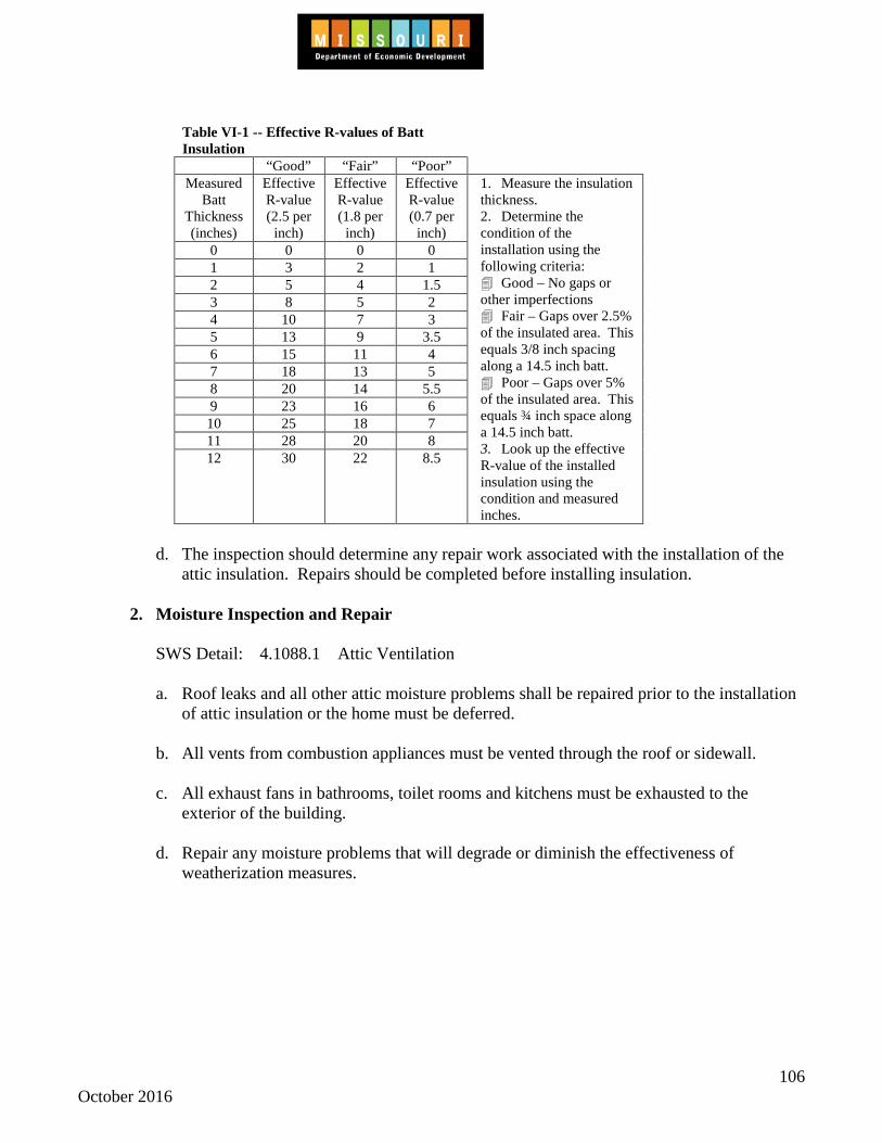
106 October 2016
Table VI-1 -- Effective R-values of Batt Insulation
“Good” “Fair” “Poor” Measured
Batt Thickness (inches)
Effective R-value (2.5 per
inch)
Effective R-value (1.8 per
inch)
Effective R-value (0.7 per
inch)
1. Measure the insulation thickness. 2. Determine the condition of the installation using the following criteria: Good – No gaps or other imperfections Fair – Gaps over 2.5% of the insulated area. This equals 3/8 inch spacing along a 14.5 inch batt. Poor – Gaps over 5% of the insulated area. This equals ¾ inch space along a 14.5 inch batt. 3. Look up the effective R-value of the installed insulation using the condition and measured inches.
0 0 0 0 1 3 2 1 2 5 4 1.5 3 8 5 2 4 10 7 3 5 13 9 3.5 6 15 11 4 7 18 13 5 8 20 14 5.5 9 23 16 6 10 25 18 7 11 28 20 8 12 30 22 8.5
d. The inspection should determine any repair work associated with the installation of the
attic insulation. Repairs should be completed before installing insulation.
2. Moisture Inspection and Repair
SWS Detail: 4.1088.1 Attic Ventilation
a. Roof leaks and all other attic moisture problems shall be repaired prior to the installation of attic insulation or the home must be deferred.
b. All vents from combustion appliances must be vented through the roof or sidewall. c. All exhaust fans in bathrooms, toilet rooms and kitchens must be exhausted to the
exterior of the building. d. Repair any moisture problems that will degrade or diminish the effectiveness of
weatherization measures.
107 October 2016
3. Electrical Safeguards
SWS Detail: 2.0601.1 Knob and Tube Wiring 4.1001.1 Non-Insulation Contact (IC) Recessed Light 4.1001.2 Knob and Tube Wiring 4.1005.2 Accessible Floors-Loose Fill Installation
a. Unsafe wiring, uncovered junction boxes or other hazardous electrical situations must be
corrected prior to performing any other work in the attic(s). If insulation exists, ensure that wiring is safe and meets applicable codes.
b. All visible electrical junctions must be installed in covered junction boxes if additional
insulation is installed. All electrical boxes will be flagged to be seen above the level of the insulation.
c. Non-Insulation Contact (IC) Recessed Lights
(1) A fire-rated air barrier system (i.e., equivalent to 5/8 fire code gypsum wallboard. will be used to separate non- IC rated recessed lights from insulation, using one of the methods below:
• A fire-rated airtight closure taller than surrounding attic insulation will be placed
over non- IC rated recessed lights OR • The non- IC rated light fixture will be replaced with an airtight and IC - rated
fixture (2) The top-fire rated enclosure material will have an R-value of 0.5 or less and will be
left free of insulation (3) The entire closure will maintain a 3" clearance between the closure and the fixture
including wiring, box, and ballast. (4) Caulk, mastic, or foam will be used on all edges, gaps, cracks, holes, and penetrations
of closure material. d. Knob and tube wiring.
(1) A contractor, assessor, auditor, or similar will inspect and assess the house to identify knob and tube wiring.
(2) A non-contact testing method will be used to identify live wiring. (3) If live knob-and tube wiring is to remain in an attic, it will not be covered or
surrounded. A dam that does not cover the top will be created to separate insulation from the wire path. Any insulation must be kept at least three inches from the wiring.
108 October 2016
(4) If live knob and tube wiring is to remain in a dwelling attic, walls or basement, the
walls of the dwelling must not be insulated. (5) Live knob and tube wiring may be replaced with WAP funds in attics and walls
provided that the cost of the replacement, when added to the cost of the attic and/or wall insulation, has an SIR of 1.0 or greater. Knob and tube wiring cannot be replaced as a health and safety or incidental repair measure.
(6) If knob and tube wiring is replaced, new appropriate wiring will be installed by a
licensed electrician in accordance with local codes. Any remaining knob and tube wiring will be rendered inoperable in accordance with local codes. If knob and tube wiring has been deactivated and the dwelling has been rewired with approved electrical cable, the attic may be insulated without special precaution.
4. Treatment of Other Hazards
a. Use appropriate personal protective equipment and work practices in the presence of animal or insect hazards. Ensure personal safety during work.
b. Repair any rotted, broken or damaged attic structural components. Ensure that the ceiling
will safely hold the weight of the insulation. Repair or replace any weakened, damaged or missing interior ceiling surface.
5. Attic Access
SWS Detail: 3.1002.2 Stairwell to Attic-Door at Bottom with No Ceiling Above 3.1002.3 Stairwell to Attic-Door at Top with Finished Ceiling Above 4.1006.2 Access Doors and Hatches
a. If attic insulation is added, access doors and pull-down stairs over living areas must be insulated with non-compressible insulation as close as possible to the same R-value as the attic. The insulation will be permanently attached and in complete contact with the air barrier. Weather-strip will be applied to prevent air leakage.
b. When it is necessary to install an interior access in the ceiling, it must be at least 20
inches by 30 inches.
c. A ceiling access shall have an insulation dam, made of rigid materials, that exceeds the height of the insulation to be installed. The dam must be strong enough to hold the weight of a person entering or exiting the attic.
d. If any work is performed in the attic of a home, an attic access must be left for inspection
purposes. If there are no interior accesses, at least one exterior access to each attic space shall be left for inspection purposes.

109 October 2016
e. If attic insulation is added, knee wall doors from the living areas to the attic must be insulated with non-compressible insulation as close as possible to the same R-value as the kneewall. The insulation will be permanently attached and in complete contact with the air barrier.
f. When it is necessary to install an interior access in a knee wall, it must be at least the
knee wall stud cavity width x 24 inches and shall be weather-stripped and insulated to the same R-value as the knee wall. A latch shall also be installed to ensure air tightness.
g. When the attic is accessed by a stairwell and attic insulation is installed, the stairwell
must be evaluated for inclusion within or exclusion from the thermal boundary in order to create a continuous thermal boundary between the attic and conditioned spaces.
(1) Stairwells with doors at the bottom may be brought into the thermal boundary or kept
out of the thermal boundary (See SWS 3.1002.2 for detailed information). (2) Stairwells with doors at the top must be brought into the thermal boundary (See SWS
3.1002.3 for detailed information) 6. Insulation Shielding and Blocking
SWS Detail: 4.1001.1 Non-Insulation Contact (IC) Recessed Light 4.1001.2 Knob and Tube Wiring 4.1001.3 Fireplace Chimney and Combustion Flue Vents
a. All electrical fixtures, excluding IC (insulation contact) rated recessed lights and covered
junction boxes, shall be blocked with rigid material, to ensure a minimum insulation clearance of 3 inches and a maximum clearance of 6 inches.
b. Insulation barriers of fire-rated material shall be used around heat-producing sources.
Barriers shall be slightly higher than the finished height of the insulation. If metal is used as an insulation barrier, a 3-inch clearance must be maintained between the metal insulation barrier and the heat-producing source and no insulation shall be left within the blocked area. Blocking must be installed so that it is effective in shielding the heat source from the insulation. Metal blocking must be notched so that it does not contact electrical wiring.
c. A fire-rated material, such as at least 26 gauge galvanized tin, must be used to seal gaps
around heat sources such as masonry or metal chimneys. This fire-rated material must be sealed with high temperature caulking to the chimney and to surrounding framing and finish materials.
(1) Un-faced fiberglass insulation with an ASTM rating as a non-combustible material of
at least 3 ½ inches in thickness, may be used to wrap the masonry chimney above this fire-rated material. This fiberglass serves as a fire shield for cellulose installed against the masonry chimney.

110 October 2016
(2) If an existing chimney or flue is treated incorrectly, correct it to comply with these
standards. If it is not reasonable to bring a chimney up to these standards, document this fact in the client file and include photographs.
d. Requirements for furnaces installed in attics:
(1) Attic furnace blocking must be installed to ensure a minimum free air clearance of 18 inches, but not more than 24 inches.
(2) If a working platform is present for an attic furnace, or if one is installed by the
subgrantee, 30 inches of clearance adjacent to the furnace controls must be provided. (3) Attic furnaces must be checked after adding attic insulation to ensure they are free of
insulation and operate properly.
B. Installation Methods for Attic Insulation 1. General Procedures
SWS Detail: 3.1001.1 Penetrations and Chases 4.1002.1 Preparation 4.1002.2 Installation 4.1005.2 Accessible Floors-Loose Fill Installation
a. Locate and seal attic bypasses, chases and open-topped partition walls. b. Properly treat ceiling height changes and stairwells as necessary to stop leakage. Seal
knee wall floor cavities. Check for completion of bypass sealing before installing any insulation.
c. Attic insulation must be installed in such a manner that ensures complete coverage over
heated areas, and is installed at an even depth except where physical constraints may exist.
d. Insulation must be installed according to the manufacturer's specifications for coverage
and R-Value. e. Attics must be tested using zonal pressure diagnostics. This test should be used to
determine quality and completeness of air leakage and bypass sealing, prior to, and then after, installing insulation. For additional information on zonal pressure diagnostics, refer to Section IV, Subsection G, Topic 4: Zonal Pressure Testing.
f. Cellulose insulation is the preferred choice for installation in site built homes and should
be used unless technical issues warrant other product consideration.

111 October 2016
g. A signed and dated attic certificate will be permanently fastened to the roof side of the attic. The certificate will include:
• Insulation type and brand • Installed thickness and settled thickness • Coverage area • R-value • Number of bags installed in accordance with manufacturer specifications • Installation date • Installed by
2. Insulation Coverage and Density
SWS Detail: 4.1002.1 Preparation 4.1002.2 Installation 4.1003.1 Pitched/Vaulted/Cathedralized Ceilings-Loose Fill Over 4.1003.2 Pitched/Vaulted/Cathedralized Ceilings-Dense Pack Over 4.1003.3 Unvented Flat Roof with Existing Insulation 4.1003.4 Cape Cod Side Attic Roof-Dense Pack Installation 4.1004.1 Preparation for Dense Packing 4.1004.2 Preparation for Batt Insulation 4.1005.1 Accessible Floors-Batt Installation 4.1005.2 Accessible Floors-Loose Fill Installation 4.1005.3 Accessible Floors-Batt Insulation Over Existing Insulation 4.1005.4 Accessible Floors-Loose Fill Over Existing Insulation 4.1005.5 Enclosed Bonus Room Floor Over Unconditioned Space-Dense 4.1005.6 Enclosed Attic Storage Platform Floor-Dense Pack Installation
a. Insulate uninsulated open-joist attics and other areas that form the thermal barrier to the
level recommended by the computerized audit program. b. Insulation will be adequately marked for depth with rulers, a minimum of every 300
square feet of attic area, with measurement beginning at the air barrier. c. At the beginning of each job, measure the density of the insulation for a selected test area
before beginning the major installation. This should be done for insulation blowing jobs using any nozzle type or tubing method.
(1) Insulate enclosed areas (under floors, slopes, under knee wall cavities, etc.) to high
density level as follows:
(a) Blown cellulose 3.5 lb/ft³
(b) Blown fiberglass 2.2 lb/ft³
(2) Insulate knee wall areas as follows:
112 October 2016
(a) Blown cellulose 3.5 lb/ft³
(b) Blown fiberglass 1.5 to 2 lb/ft³
(c) Fiberglass batts R-19
d. Calculating the number of bags is the preferred method for determining the proper
amount of material to be installed into an attic area at a given R-value. e. When a vapor barrier is installed with the insulation, the barrier should be installed on the
warm side of the insulation and never more than 1/3 of the R-value away from the warm-side surface.
f. Add necessary insulation to eliminate voids and areas of incomplete coverage. Cut or
pull back existing fiberglass batts two feet from the soffit and blow and dense pack the perimeter. Prepare floored areas or other restricted zones with existing insulation for high-density application.
3. Enclosed Ceiling Cavities When insulating enclosed ceiling cavities, it is preferred that insulation be installed from a
location other than through roofing material. Such locations may include rafter cavities that open into an attic area, through the eave, or from the interior of the home.
4. Storage Space Where attic space is being used for storage, subgrantees should request the client remove
storage items from the area. In cases where the client is physically unable to perform this task, subgrantees should include the removal of items in the cost-effective analysis of installing insulation, and proceed with the measure if it is cost-effective (savings-to-investment ratio of 1.0 or greater).
5. Ductwork Insulation
SWS Detail: 4.1601.1 Insulating Flex Ducts 4.1601.2 Insulating Metal Ducts 4.1601.3 General Information on Spray Polyurethane Foam (SPF)
a. When attic insulation is installed, all uninsulated ductwork in the attic must be insulated. Install a minimum of R-8 (preferably R-11 or greater, when possible) on ducts and
plenums. Whenever it is cost-effective, the installation of spray polyurethane foam is recommended where it can achieve both insulation and air sealing value. If spray polyurethane foam is not cost-effective, it is preferred that attic ducts be draped with an un-faced blanket insulation and blown over with loose fill insulation, to at least the depth
113 October 2016
of the surrounding insulation. If faced duct insulation is installed, it is preferred that the facing be to the outside. Bubble wrap (foil faced or non-foil faced) should not be used to comply with the minimum R-8 value required for ductwork, as bubble wrap applied to the surface of ductwork only provides a value of approximately R-1.1. Ductwork with existing bubble wrap may be evaluated as uninsulated.
b. All joints, seams, and connections in ductwork shall be securely fastened and sealed with
the proper materials (fiberglass mesh and mastics or spray foam) before insulation is installed. The cost for applying spray polyurethane foam can be split between both duct sealing and insulating of ductwork to have a better possibility of both having an SIR of 1.0 or greater.
c. A minimum of 6 inches clearance between duct insulation and heat sources must be
maintained, unless the material is rated for closer proximity. 6. Drill-and-Blow Patching If a drill-and-blow method is used for installing ceiling insulation, holes must be properly
plugged, secured with adhesives, and sealed.
C. Attic Ventilation
SWS Detail: 4.1001.4 Vented Eave or Soffit Baffles 4.1088.1 Attic Ventilation
1. General Installation
a. Ensure that existing vents are not blocked, crushed or otherwise obstructed. Correct problems as necessary, or replace.
b. When attic ventilation is installed, use the following guideline unless local code
supersedes:
If air-sealing work has been completed at the attic floor then one square foot of net-free ventilation may be installed for every 300 square feet of attic floor area.
c. Attic vent types will be made of corrosion-resistant material for their specific location
(e.g., exterior soffit, gable end, roof) and material and intended use (e.g., metal vent on metal roof).
d. All ventilation openings should have suitable louvers and screens to prevent snow, rain
and pests from entering the attic. Screens will be made of non-corroding wire mesh with openings of 1/16" to 1/4" to prevent pest entry
e. Placement of attic vents will be considered for proper air flow and prevention of entry of wind driven rain or snow.
114 October 2016
2. Soffit Vents
When soffit vents are present, baffling for attic soffit vents will be installed to: (a) Ensure proper air flow (b) Prevent wind washing of insulation (c) Allow for maximum insulation coverage
3. High-Low Vents
a. Roof vents should be installed close to the peak. b. Install high gable vents at least 3 feet above the soffit or gable vent used for low venting. c. When roof vents are installed they should be nailed and well-sealed to the roof to prevent
water leakage. 4. Gable Vents
a. Gable-end vents should be installed as high in the gable as possible and positioned to provide cross ventilation.
b. Steps shall be taken to prevent wind washing of insulation around the attic vents.
5. Knee Wall Ventilation
Knee wall attics or attic spaces that are sealed from other attic spaces may need to be ventilated as if they are a separate attic.
D. Sidewall Insulation
1. General Procedures
SWS Detail: 4.1101.1 Exterior Wall Dense Packing 4.1101.2 Exterior Wall Insulating Sheathing 4.1103.1 Dense Pack Exterior Walls 4.1103.2 Additional Exterior Wall Cavities 4.1103.3 Insulated Sheathing and Insulated Siding Installation
115 October 2016
a. An inspection from the interior and exterior of the home should be performed prior to installing insulation. This inspection should identify all potential hazards and needed repairs.
b. An inspection from the exterior of the home should include an examination of the
following:
(1) Building construction details. (2) Siding type and condition. (3) The location of electrical, gas, oil and phone lines. (4) Plumbing pipes.
(5) Existing moisture and drainage problems. (6) Existing structural problems.
c. An inspection from the interior of the home should include an examination of the
following:
(1) Interior wall siding type and condition. (2) Electrical and plumbing utilities. (3) Duct work in wall cavities. (4) Dropped or suspended ceilings. (5) Moisture problems.
d. An inspection from the attic should include an examination of the following:
(1) Open top plates and balloon framing. (2) Type of electrical wiring in the walls. (3) Knee wall areas.
e. Correct electrical problems such as unsafe wiring, uncovered junction boxes or electrical
situations which must be corrected prior to performing any insulation work. If insulation exists, ensure that wiring is safe and meets applicable codes.
f. Live knob and tube wiring may be replaced with WAP funds in attics and walls provided
that the cost of the replacement, when added to the cost of the attic and/or wall insulation,

116 October 2016
has an SIR of 1.0 or greater. Knob and tube wiring cannot be replaced as a health and safety or incidental repair measure.
(1) If active knob and tube wiring remains in the dwelling attic, walls or basement, the
walls of the dwelling must not be insulated. Unless it is cost effective to rewire and the rewiring is completed before insulating.
(2) If knob and tube wiring has been deactivated and the dwelling has been rewired with
BX, Romex, or other approved electrical cable, the walls may be insulated without special precaution.
g. Any wall that contains vermiculite must follow the guidelines given in Section II,
Subsection B, Topic 10: Hazardous Conditions and Materials. 2. Moisture Inspection and Repair
SWS Detail: 2.0401.1 Air Sealing Moisture Precautions a. Any leaks or other moisture problems must be repaired prior to installing wall insulation. b. Repair any moisture problems that will degrade or diminish the effectiveness of
weatherization measures. 3. Treatment of Other Hazards
a. Use appropriate personal protective equipment and work practices in the presence of animal or insect hazards. Ensure personal safety during work.
b. Remove any items that inhibit the ability to install wall insulation effectively. c. Repair any rotted, broken or damaged structural components. Ensure that the finished
wall material will safely withstand the pressure of the insulation. Repair or replace any weakened, damaged or missing interior wall surface.
4. Interior Inspection and Repairs
SWS Detail: 4.1101.1 Exterior Wall Dense Packing 4.1102.1 Open Wall Insulation-General 4.1102.2 Open Wall-Spray Polyurethane Foam (SPF) Installation
a. Repair or replace week or damaged drywall or lath and plaster sections. Locate any
interior areas of paneling with no sub-wall surfaces or that are not securely fastened. Determine an insulation strategy which will not damage the paneling. Repair or replace damaged or missing baseboard, casing, jambs, etc., that may allow insulation to escape from the wall cavity. Holes drilled for insulation must be finished and returned to a
117 October 2016
condition as close to the original as possible. Interior holes will be masked and dust controlled during drilling when accessing from interior.
b. Locate the positions of all wall-mounted switches and outlets before beginning insulation
work. Locate all chases, utility runs, duct runs, wall heaters, vent fan penetrations, etc. prior to insulating. Block around these areas, if possible. If it is not possible to block around an area, avoid that area when insulating.
c. Find any interior soffit areas, pocket doors, or other structural details which may need
preparation prior to insulating, and prepare as necessary. Locate critical framing junctures and ensure adequate insulation density.
5. Exterior Inspection and Repairs
SWS Detail: 4.1101.1 Exterior Wall Dense Packing 4.1102.1 Open Wall Insulation-General 4.1102.2 Open Wall-Spray Polyurethane Foam (SPF) Installation
a. Note all types of siding material. Note siding material which may contain asbestos and if
present refer to Section II, Subsection B, Topic 10 Hazardous Conditions & Materials. Wherever possible, determine the presence and condition of previous layers of siding or sub-siding. Determine the best drilling strategy (the tubing method or the nozzle method. As the primary acceptable method, the siding must be lifted or temporarily removed to gain access for drilling. Permission is needed from the client to drill through any type of exterior siding.
b. Repair or replace severely deteriorated window or door components as needed to install
insulation. c. Patch holes in exterior walls. d. Determine the source and correct any problem which has led to moisture in wall cavities
prior to installing insulation. Repair or replace damaged, rotted or deteriorated siding to ensure the integrity of the insulation. If any missing siding, flashing, etc. would allow deterioration of installed insulation, replace it with a compatible material.
e. Access structural additions and critical junctures to determine the ability of these areas to
contain high-density insulation. Correct any openings or gaps prior to installing insulation.

118 October 2016
E. Installation Methods for Wall Insulation 1. General Procedures
SWS Detail: 4.1103.1 Dense Pack Exterior Walls 4.1103.2 Additional Exterior Wall Cavities 4.1103.3 Insulated Sheathing and Insulated Siding Installation
a. Wall areas above windows and doors (except in mobile homes), and the area below
windows must be insulated, whenever possible. These cavities made need to be drilled and blown separately.
b. Uninsulated exterior walls without drywall, paneling or other interior finishing material,
must be insulated if adding interior finishing material and insulation is deemed cost-effective.
c. Fiberglass insulation must not be left exposed in living spaces or in other spaces that are
routinely used by the client. Fiberglass may be encapsulated or covered with a durable, air-permeable material such as Tyvek or landscaping fabric.
d. Removal of siding before drilling the sheathing is considered “best practice” and should
be the method used unless conditions make this impossible or an unacceptable risk. e. Dense pack insulation will be installed using the tube-fill method. Using fill tube, 100%
of each cavity will be filled to a consistent density. For additional information, see the Missouri Weatherization Field Guide, Chapter 5: Walls.
2. Blocking
SWS Detail: 4.1101.1 Exterior Wall Dense Packing
a. Construction details that allow insulation to escape from sidewall cavities such as balloon framed walls must be blocked or packed with insulation or other material in a manner that effectively retains the insulation material.
3. Materials
SWS Detail: 4.1101.1 Exterior Wall Dense Packing 4.1101.2 Exterior Wall Insulating Sheathing 4.1102.2 Open Wall—Spray Polyurethane Foam (SPF) Installation
a. Site-built homes:
(1) Insulate all closed-cavity sidewalls with cellulose insulation unless this is not possible. If it is not possible, documentation for the reason must be included in the client file.

119 October 2016
(2) Insulate open cavity walls with fiberglass, faced or unfaced, using a density and
thickness appropriate for the cavity. Cover any flammable insulation facing or vapor barrier installed in a living space with a fifteen-minute fire rated material such as 1/2 inch drywall (taped once) or 3/4 inch plywood.
(3) Rigid plastic insulation or spray polyurethane foam (SPF) may be used when
appropriate. Cover any rigid insulation, SPF or vapor barrier installed in a living space with a fifteen-minute fire rated material such as 1/2 inch drywall (taped once), 3/4 inch plywood or a UL 1775 listed thermal barrier intumescent coating.
b. For mobile home wall insulation materials, refer to Section VIII, Subsection F: Sidewall
Insulation.
4. Insulation Coverage, Density and Voids SWS Detail: 4.1101.1 Exterior Wall Dense Packing
a. Sidewall insulation must be installed according to manufacturers' recommended density,
and in such a manner that does not allow settling of the material to occur. b. Determine the appropriate sidewall insulation technique(s) to be used. When dense pack
insulation is installed, the tube-fill method must be used. c. Insulate all sidewalls to a minimum density of 3.5 lb/ft³ with cellulose insulation, unless a
technical barrier prevents this technique. d. When using blown fiberglass, install at a density of 1.5 to 2 lb/ft³. e. The number of bags installed will be confirmed and will match the number required on
the coverage chart. f. Insulation density will be verified by bag count, core sampling, or with diagnostic
methods such as infrared camera or chemical smoke with the blower door at 50 pascals of pressure difference.
g. Subgrantees should obtain a warranty, of at least one-year, against voids of more than 5
percent from subcontractors installing wall insulation. 5. Plugs and Patching
SWS Detail: 4.1103.2 Additional Exterior Wall Cavities
a. Where possible, exterior lap siding must be removed and sheathing be drilled for the installation of insulation. Exterior holes will be weather barrier patched. If the exterior siding is properly shedding water, then patching of holes in the sub-siding is not required.
120 October 2016
Small pieces of fiberglass insulation can be inserted into the hole to prevent wicking of moisture from outside.
(1) Plugs that are compatible with the siding or wall type must be used to cover the
exposed surface that has been drilled. (2) Plugs must be sealed tightly and glued. They must be primed when exposed to
weather. b. Interior holes will be coated and patched to match as close to the original interior surface
as possible. Subgrantees or their contractors should paint and may texture to match plugs to the surrounding wall, but may not paint or texture the entire wall.
6. Brick Siding Interior drill and blow techniques are preferred for homes with brick veneer siding that are
going to receive sidewall insulation. 7. Quality Control When possible, infrared scanning should be used with a blower door as a quality control tool
to check wall insulation work and identify areas of excessive air leakage. The infrared scanning device is a powerful tool for finding air leaks when used in conjunction with a blower door. Subgrantees are advised to use infrared scanning whenever the equipment is available and the use is practical.
F. Foundation Insulation
This section addresses rim joist insulation, basement wall insulation, and crawl space wall insulation. SWS Detail: 2.0111.1 Basements and Crawl Spaces Worker Safety
2.0111.2 Crawl Spaces-Pre-Work Qualifications 1. General Procedures
a. An inspection from the interior and exterior of the home should be performed prior to installing insulation. This inspection should identify all potential hazards and needed repairs.
b. An inspection from the exterior of the home should include an examination of the
following:
(1) Building construction details. (2) Foundation type and condition.

121 October 2016
(3) The location of electrical, gas, oil and phone lines. (4) Plumbing pipes. (5) Existing moisture and drainage problems. (6) Existing structural problems.
c. An inspection from the interior of the home should include an examination of the
following:
(1) Interior foundation wall type and condition. (2) Electrical and plumbing utilities. (3) Moisture problems.
d. Make any necessary repairs before installing insulation. e. If any work is performed in the subspace of the home, an access must be left accessible
for inspection purposes. 2. Moisture Inspection and Repair
SWS Detail: 2.0401.2 Vented Crawl Space-Venting 2.0402.1 Crawl Spaces-Drainage 2.0403.1 Vented Crawl Spaces-Ground Moisture Barrier 2.0403.2 Closed Crawl Spaces-Ground Moisture Barriers 2.0403.3 Closed Crawl Spaces-Vapor Retarders on Walls
a. All units must be inspected for problems associated with excess moisture. b. Identification of potential moisture problems shall be documented in the client file. c. Repair any moisture problems that will degrade or diminish the effectiveness of
weatherization measures. d. For crawl spaces and basements with exposed dirt floors, refer to Section II, Subsection
B, Topic 9: Moisture.

122 October 2016
3. Wall Moisture Barrier
SWS Detail: 2.0403.3 Closed Crawl Spaces-Vapor Retarders on Walls 4.1402.3 Basement Wall Insulation-Ground Water Leakage
If there is evidence of water leakage or moisture coming through the foundation wall from the exterior, a continuous moisture barrier must be attached from the top of the sill plate to the top of the slab in a manner that drains the moisture behind the insulation to be installed, and covers the insulated section of the foundation or crawl space wall.
4. Treatment of Other Hazards
a. Use appropriate personal protective equipment and work practices in the presence of animal or insect hazards. Ensure personal safety during work and exercise the deferral policy when appropriate.
b. Repair any rotted, broken or damaged structural components as necessary to install
ECM's. 5. Defining the Thermal Boundary
SWS Detail: 3.1401.1 Basements Connected to Crawl Spaces-Sealing and Insulating
a. If the basement or crawl space meets the criteria to be a conditioned space as stated in Section IV, Subsection A, Topic 1: Preparation for a Blower Door Test, it must be treated as a conditioned area. In this case, the basement or crawl space walls are part of the boundary of the conditioned envelope. Therefore, it is preferred to air seal and insulate the basement or crawl space walls because this strategy encloses the furnace, ducts, pipes, water heater and other appliances within the conditioned envelope.
b. Unconditioned basements and crawl spaces must be tested using zonal pressure
diagnostics when the housing construction type or the air leakage rate indicates that there may be hidden air leakage or bypass pathways into the basement or crawl space. This test should be used to determine quality and completeness of air leakage and bypass sealing, prior to, and then after, installing insulation. In addition, this test can help determine the appropriate location of the thermal boundary.
c. If the appropriate thermal boundary is determined to be the basement or crawl space wall,
rather than the floor above the basement/crawl space, then the basement or crawl space wall should be sealed, as necessary, before any insulation is installed on these surfaces.
d. If a basement and crawl space are not separated by a continuous air barrier, both areas
must be assessed the same (e.g., conditioned or unconditioned).
123 October 2016
G. Foundation Insulation Installation Methods
SWS Detail: 2.0111.1 Basements and Crawl Spaces Worker Safety
1. Storage Space
a. Where the basement or crawl space is being used for storage, subgrantees should request the client remove storage items from the area that inhibit weatherization.
b. In cases where the client is physically unable to perform this task, subgrantees should
include the removal of items that inhibit weatherization in the cost-effective analysis of installing insulation, and proceed with the measure if it is cost-effective with additional costs (savings-to-investment ratio of 1.0 or greater).
2. Materials
SWS Detail: 4.1102.2 Open Wall—Spray Polyurethane Foam (SPF) Installation 4.1401.1 Band/Rim Joists-Spray Polyurethane Foam (SPF) Installation 4.1402.1 Closed Crawl Spaces-Wall Insulation 4.1402.2 Basement Wall Insulation-No Ground Water Leakage 4.1402.3 Basement Wall Insulation-Ground Water Leakage 4.9901.1 General Information on Spray Polyurethane Foam (SPF)
a. Interior wall insulation:
(1) If the wall is studded out on the interior, it may be filled with unfaced fiberglass batt
of an appropriate thickness or with vinyl-faced fiberglass (metal building insulation). (2) Vinyl-faced fiberglass (metal building insulation) may be fastened at the band joist
area and hung down four feet. (3) An alternative method for installing perimeter insulation is to attach metal-building
insulation at the floor above the rim, so that the blanket extends from the floor above four feet down the foundation wall. It should be run horizontally in a continuous manner to eliminate as many seams as possible. The blanket may be slit at each floor joist to allow installation in a manner that minimizes gaps around the joist. The bottom of the bottom of this fiberglass batt insulation should be air sealed to the wall with a strip of wood nailed to the foundation or by sealing the vinyl facing to the wall with adhesive caulk.
(4) Interior rigid foam insulation may be glued and fastened or SPF applied to the
basement or crawlspace wall. If the basement or crawlspace is used as a living space or a storage space, the rigid foam insulation and/or the SPF will be separated from the space using a thermal barrier material (e.g. ½ inch gypsum wallboard).

124 October 2016
(4) All costs associated with this measure should be included in the cost-effective analysis of the wall insulation and proceed with the measure if it is has a savings-to-investment ratio of 1.0 or greater and cost controls will permit installation.
b. Exterior wall insulation:
(1) Foundation panels (factory pre-finished on exterior) may be used if they are glued
and fastened, has drip caps installed, and is sealed around windows. They must extend at least 6 inches below the finished grade.
(2) Extruded polystyrene may be used that is not pre-finished if glued and fastened, has
drip caps installed, and is sealed around windows. The insulation must extend at least 6 inches below the finished grade. The exterior surface of these panels must be covered with a material that will protect it from ultra-violet light.
(3) All costs associated with this measure should be included in the cost-effective
analysis and proceed with the measure if it is has a savings-to-investment ratio of 1.0 or greater.
c. Insulation Coverage
SWS Detail: 4.1401.1 Band/Rim Joists-Spray Polyurethane Foam (SPF) Installation (1) Insulation must be installed in a manner that provides as continuous a thermal
boundary as possible. (2) Perimeter insulation must not be installed in a manner that excessively compresses
the insulation material. d. Band and Rim Joist Insulation
SWS Detail: 4.1401.1 Band/Rim Joists-Spray Polyurethane Foam (SPF) Installation
(1) Rim joist insulation must be a minimum of R-10. (2) Fiberglass, rigid foam board or spray polyurethane foam insulation may be used for
this application. Whichever is used must result in a savings-to-investment ratio of at least 1.0.
(3) If there is significant air leakage, the band or rim joist area must be properly sealed
before the insulation is installed. Spray polyurethane foam is recommended where it can achieve both insulation and an air sealing value. The cost for applying spray polyurethane foam can be split between both infiltration reduction and insulating of band or rim joist work to have a better possibility of both having a SIR of 1.0 or greater.

125 October 2016
(4) Installed insulation must be secured in a permanent manner. (5) Fiberglass insulation must not be left exposed in living areas.
e. Foundation Insulation
SWS Detail: 4.1402.1 Closed Crawl Spaces-Wall Insulation 4.1402.2 Basement Wall Insulation-No Ground Water Leakage 4.1402.3 Basement Wall Insulation-Ground Water Leakage
(1) Foundation walls should be insulated so that no portion above grade is left
uninsulated. (2) Fiberglass insulation must not be left exposed in living areas or in other spaces that
are routinely used by the client. Fiberglass may be encapsulated or covered with a durable, air-permeable material such as Tyvek or landscaping fabric.
(3) Mechanical fasteners must be used to secure perimeter insulation in a permanent
manner.
(4) Basement wall insulation must be a minimum of R-7.5.
3. Crawl Space Insulation
SWS Detail: 3.1402.1 Crawl Spaces-Sealing Floor Penetrations 4.1402.1 Closed Crawl Spaces-Wall Insulation
a. Separate an unconditioned crawl space from an adjoining conditioned basement with suitable materials.
b. Seal all direct air leakage sites into the crawl space from the exterior if the crawl space is
conditioned. c. Seal all bypasses and chases into and through the conditioned areas of the house. d. Install perimeter insulation from the band joist to the crawl space floor. The crawl space
wall insulation shall extend downward:
(1) to a distance that is two feet below the exterior grade, or (2) to the crawl space floor and then horizontally across the floor for two feet, whichever
is appropriate. Mechanically fasten the insulation and seal all joints with tape. e. An alternative method for installing interior perimeter insulation is to attach metal-
building insulation at the floor above the rim, so that the blanket extends from the floor

126 October 2016
above to four feet down the wall. It should be run horizontally in a manner that minimizes the number of seams. The blanket may be slit at each floor joist to allow installation in a manner that minimizes gaps around the joist. This insulation should extend downward to a distance that is two feet below the exterior grade or to the crawl space floor and then horizontally across the floor for two feet, whichever is appropriate. Mechanically fasten the insulation and seal all joints with tape.
H. Floor Insulation
1. General Procedures
SWS Detail: 2.0111.1 Basements and Crawl Spaces Worker Safety
a. Precautions must be taken to insure adequate combustion air is being supplied, through non-operable vents, for combustion appliances in crawl spaces.
b. If any work is performed in the subspace of the home, an access must be left accessible
for inspection purposes. 2. Moisture Inspection and Repairs
SWS Detail: 2.0401.2 Vented Crawl Space-Venting 2.0402.1 Crawl Spaces-Drainage 2.0403.1 Vented Crawl Spaces-Ground Moisture Barrier 2.0403.2 Closed Crawl Spaces-Ground Moisture Barriers 2.0403.3 Closed Crawl Spaces-Vapor Retarders on Walls
a. All homes where floor insulation is being installed must be inspected for problems
associated with excess moisture. b. Identification of potential moisture problems shall be documented in the client file. c. Repair moisture problems that will degrade or diminish the effectiveness of
weatherization measures.
d. If floor insulation is installed over a crawl space area, install a 6 millimeter or thicker polyethylene vapor barrier on the earthen floor. For additional information on vapor barrier installation, see Section II, Subsection B, Topic 9: Moisture.
3. Defining the Thermal Boundary
SWS Detail: 2.0104.1 Insulation Worker Safety 2.0111.1 Basements and Crawl Spaces Worker Safety 3.1401.1 Basements Connected to Crawl Spaces-Sealing and Insulating

127 October 2016
a. If the basement or crawl space meets the criteria to be a conditioned space as stated in Section IV, Subsection A, Topic 1: Preparation for a Blower Door Test, Subtopic g, Details 1-6, it must be treated as a conditioned area. In this case, the basement or crawl space walls are part of the boundary of the conditioned envelope. Therefore, it is preferred to air seal and insulate the basement or crawl space walls because this strategy encloses the furnace, ducts, pipes, water heater and other appliances within the conditioned envelope.
b. Unconditioned basements and crawl spaces must be tested using zonal pressure
diagnostics when the housing construction type or the air leakage rate indicates that there may be hidden air leakage or bypass pathways into the basement or crawl space. This test should be used to determine quality and completeness of air leakage and bypass sealing, prior to, and then after, installing insulation. In addition, this test can help determine the appropriate location of the thermal boundary.
c. If the appropriate thermal boundary is determined to be the basement or crawl space wall,
rather than the floor above the basement/crawl space, then the basement or crawl space wall should be sealed, as necessary, before any insulation is installed on these surfaces.
d. If a basement and crawl space are not separated by a continuous air barrier, both areas
must be assessed the same (e.g., conditioned or unconditioned).
I. Installation Methods for Floor Insulation
SWS Detail: 2.0104.1 Insulation Worker Safety 1. General Procedures
SWS Detail: 4.1301.1 Standard Floor System-Batt Installation 4.1301.5 Cantilevered Floor-Batt Installation 4.1301.9 Open Floors Over Unconditioned Space and Cantilevered Floors,
Floors Over Garages, Floors Over Unconditioned Crawl Spaces-Spray Polyurethane Foam (SPF))
a. Install a minimum of R-11insulation between the floor joists. b. The insulation should be installed without voids or gaps. Fit insulation tightly around all
cross bracing and any obstructions. c. Floor insulation must be fastened securely in place with wire fasteners, nylon mesh or
other appropriate methods. Friction fitting or stapling of floor insulation is not considered an appropriate method for securing the material. Do not support insulation with Tyvek or Typar sheeting stapled to the bottom edges of the joists.
d. Install insulation so that it is in contact with the underside of the sub floor above with no
voids or gaps.

128 October 2016
e. Faced fiberglass insulation must have the facing upward toward the heated area. f. Ensure that floor insulation is in direct contact with the rim joints. If the dwelling is
balloon-framed, air-seal the bottom of the stud cavities prior to installing insulation. g. Fiberglass insulation must not be left exposed in living spaces or in other spaces that are
routinely used by the client. Fiberglass may be encapsulated or covered with a durable, air-permeable material such as Tyvek or landscaping fabric.
2. Materials
SWS Detail: 4.1301.1 Standard Floor System-Batt Installation 4.1301.5 Cantilevered Floor-Batt Installation 4.1301.9 Open Floors Over Unconditioned Space and Cantilevered Floors,
Floors Over Garages, Floors Over Unconditioned Crawl Spaces-Spray Polyurethane Foam (SPF))
a. Spray polyurethane foam, fiberglass (faced or un-faced) insulation is preferred for floor
insulation material. Whichever is used must result in a savings-to-investment ratio of at least 1.0.
b. If there is significant air leakage, the floor area must be properly sealed before the
insulation is installed. Spray polyurethane foam is recommended where it can achieve both insulation and an air sealing value. The cost for applying spray polyurethane foam can be split between both infiltration reduction and insulating the floor to have a better possibility of both having a SIR of 1.0 or greater.
c. It is preferred that vinyl faced insulation not be used for floor insulation.
3. Insulation Coverage Procedures
SWS Detail: 4.1301.1 Standard Floor System-Batt Installation 4.1301.5 Cantilevered Floor-Batt Installation 4.1301.9 Open Floors Over Unconditioned Space and Cantilevered Floors,
Floors Over Garages, Floors Over Unconditioned Crawl Spaces-Spray Polyurethane Foam (SPF))
a. Floor insulation must be installed in a manner that provides as continuous of a thermal
boundary as possible. b. Floor insulation must not be installed in a manner that excessively compresses the
material. 4. Storage Space

129 October 2016
a. Where the basement or crawl space is being used for storage, subgrantees should request the client remove storage items that inhibit weatherization from the area.
b. In cases where the client is physically unable to perform this task, subgrantees should
include the removal of items that inhibit weatherization in the cost-effective analysis of installing insulation, and proceed with the measure if it is cost-effective with the additional cost (savings-to-investment ratio of 1.0 or greater).
5. Ducts and Pipes Procedures
SWS Detail: 3.1602.1 Air Sealing Duct System 3.1602.7 Return and Supply Plenums in Basements and Crawl Spaces 4.1601.2 Insulating Metal Ducts
a. When floor insulation is installed, any water pipe that is susceptible to freezing, and all
furnace supply and return ducts below the insulation, must be insulated as part of the floor insulation measure or insulated as a duct insulation measure, given it has an SIR of 1.0 or greater.
b. Do not insulate over pumps, valves, pressure relief devices or vents; do not insulate over
heat tape unless manufacturers' specification indicate that such insulation is safe. 6. Crawl Space Ventilation
SWS Detail: 2.0401.2 Vented Crawl Space-Venting
a. Conditioned crawl spaces:
If crawl space walls are insulated, the crawl space shall not be vented to the outdoors. b. Unconditioned crawl spaces:
Crawl space ventilation is not necessary if the crawl space is well drained and dry. c. Crawl space vents shall be louvered and screened or otherwise designed to prevent the
entry of snow, rain and critters into the building. d. If operable crawl space vents are installed, the client must be informed of the benefits of
closing the vents in winter and opening the vents in summer. e. If excess ventilation is present, it is preferred that it be closed off with removable rigid
insulation. Where possible, close off vents on the windward side of the crawl space. Do not close off combustion air vents.

130 October 2016
THIS PAGE IS INTENTIONALLY LEFT BLANK FOR FUTURE EXPANSION
131 October 2016
Section VII: Baseload
A. Energy-Saving Showerheads and Faucet Aerators SWS Detail: 2.0107.1 Baseload Worker Safety
7.8101.1 Shower Head and Faucet Aerator 1. An energy-saving (low-flow) showerhead may be installed with client permission. The
energy-saving showerhead must have a flow rating of 2.5 GPM or less and must cost test with a SIR of 1.0 or greater.
2. Energy-saving (low-flow) faucet aerators may be installed with client permission. Aerator
flow rate will be 2.2 GPM or less and must cost test with a SIR of 1.0 or greater.
B. Plug Load 1. Refrigerators/Freezers
SWS Detail: 7.8001.1 Refrigerator and Freezer Replacement
a. Only new refrigerators and refrigerator/freezers can be installed in weatherized housing. Stand-alone upright and chest freezers cannot be installed. However, if upright or chest model types are determined to be energy inefficient, agencies may encourage clients to decommission them as part of the refrigerator replacement. Agencies may decommission a combination of stand-alone upright freezers, chest freezers and/or refrigerator/freezers and replace them with a new refrigerator/freezer if the energy savings compared to both the existing units justify the measure. The replacement refrigerator must be an Energy Star-rated energy-efficient refrigerator with an estimated annual consumption of 600 kWh/yr or less. The replacement refrigerators must be equipped with either manual, automatic or partial-automatic defrost. New replacement units may not have through-the-door ice or water service as this feature increases energy use. However, DED/DE will allow refrigerators to have an automatic ice maker in the freezer if there is an existing water line hook-up for the icemaker in the home.
b. Refrigerator replacements are limited to one per household. Unless there are special
conditions, the refrigerator to be replaced must be the primary unit used by the household.
c. Refrigerator replacement must result in a savings-to-investment ratio (SIR) of 1.0 or
greater. d. There are two methods to estimate the savings that result from replacing an existing
refrigerator. These methods should be incorporated into the initial energy audit.

132 October 2016
(1) Check the data plate on the refrigerator. The Association of Home Appliance Manufactures’ database which is incorporated into computerized audit may be used to estimate the annual energy use of existing refrigerators.
(2) Use a meter to determine the energy usage of the appliance.
e. In accordance with DOE guidance, DED/DE will require all agencies to meter at least 10% of the units replaced. Prior to metering, the refrigerator coils must be cleaned and the thermostat must be set within the ranges of 36º to 40º F for the refrigerator and 0º to 5º F for the freezer. If the existing refrigerator is non-functional and unable to be metered, it is ineligible to be replaced.
f. All refrigerators replaced must be properly decommissioned according to the
environmental standards in the Clean Air Act of 1990, section 608, as amended by Final Rule 40 CFR 82, May 14, 1993. The environmental standards set certification requirements for recycling and recovering equipment, technicians and reclaimers. These standards require refrigerants to be recovered to avoid the release of ozone-depleting compounds into the atmosphere. No refrigerator or freezer that is taken out of service should be returned to service by sale, barter or for free. Written documentation/ certification that the refrigerator has been properly decommissioned must be included in the Client File.
g. Size of the replacement refrigerator should be comparable to the size of the unit being
replaced. The agency may, on a case-by-case basis, provide a refrigerator larger than the unit being replaced. If a larger refrigerator is installed, the refrigerator replacement must still have an SIR of 1.0 or greater. Some conditions where a larger unit may be installed may include but not limited to:
(1) A larger unit costing less than the similar size being replaced, larger unit needed due
to size of family. (2) A larger size needed due to medical condition of family member, decommissioning a
combination of refrigerators and/or freezers. h. Replacement refrigerators must include a warranty that meets or exceeds:
(1) A one year warranty on parts and labor. (2) A minimum five year warranty on the compressor.
i. Refrigerator replacements will be limited to owner-occupied units. j. A completed Baseload Replacement Audit Form must be included with the Client File for
each refrigerator to be replaced. (See Attachment 2.6) 2. Lighting Replacement

133 October 2016
SWS Detail: 7.8003.1 Lighting Upgrade
Most homes have six to twelve lamps that burn for more than two hours per day. These should be considered for retrofit by more-efficient compact fluorescent lamps (CFLs) and/or light emitting diodes (LEDs). This easy retrofit has as good an economic return as any weatherization measure. Explain the benefits to the client and encourage them to purchase additional CFL bulbs, if possible. Point out that the long life of these lamps makes them economical, despite their higher initial cost.
a. All lighting replacement must have an individual measure SIR of 1.0 or greater. b. All lighting replacements must be installed by the subgrantee. Lighting replacements
cannot be left with the client to install. c. All replaced lighting must be removed from the property and be properly discarded.
THE REMAINDER OF THIS PAGE IS INTENTIONALLY LEFT BLANK FOR FUTURE EXPANSION

134 October 2016
THIS PAGE IS INTENTIONALLY LEFT BLANK FOR FUTURE EXPANSION

135 October 2016
Section VIII: Mobile Home Requirements
The same general procedures described in all other sections of these WAP Standards shall apply to mobile homes unless otherwise stated or stated more specifically in this section.
A. Inspections and Repairs
1. General Information
a. The structure shall be properly supported, leveled and secured, if required, at the homeowner’s expense before weatherization measures are installed.
b. Existing structural problems which may affect insulation measures must be completed
prior to installing insulation. c. Belly rodent barrier damages must be repaired if insulation will be installed or if
significant air leakage is occurring. d. Minor skirting repairs may be performed as an incidental repair tied to belly insulation or
infiltration reduction if either is occurring in the belly of the mobile home. The minor skirting repairs are limited to a maximum total of $200 labor and materials per home.
2. Moisture Problems
SWS Detail: 2.0401.1 Air Sealing Moisture Precautions
a. If moisture problems are present in the ceiling or sidewalls, insulation should not be added until the moisture source and/or site of penetration, including leaks, is identified and repaired.
b. Exhaust-fan ducts terminating in spaces such as ceiling cavities or crawl spaces shall be
extended to terminate directly to the outdoors, and sealed to prevent exhaust air from returning back into the conditioned space.
3. Electrical Inspections
SWS Detail: 2.0602.1 Static Electric Shock 2.0602.2 House Current Electric Hazard
a. In units that are receiving insulation measures, electrical wiring and the electrical circuit
breaker/fuse box must be assessed for adequacy as follows: #14 copper wiring must be protected with 15 amp fusing or breakers. If aluminum wiring is present, work on the home will be stopped until the suspect wiring is inspected and determined to be safe by a licensed electrician
b. The client should be asked about any known existing electrical problems.
136 October 2016
c. Care must be taken to ensure that electrical wiring is not damaged during insulation
work. This can be done by testing electrical outlets and switches following completion of work.
B. Air Leakage Reduction Requirements
1. General Requirements
SWS Detail: 3.1001.4 General Penetrations 3.1101.1 Exterior Holes and Penetrations 3.1101.2 Interior Holes and Penetrations 3.1101.3 Holes, Penetrations, and Marriage Line 3.1201.5 Manufactured Housing Windows and Doors 3.1201.6 Interior Storm Windows 3.1202.3 Replacing Damaged Window Glass in Manufactured Housing 3.1301.1 Electrical, HVAC, Plumbing, Gas, Dryer Vent, and General
Penetrations Through Bottom Board 3.1301.2 Electrical, HVAC, Plumbing, Gas, Dryer Vent, and General
Penetrations Through Flooring 3.1302.1 Floor Framing-Bay Window
a. Except for the sealing of ductwork and large holes to prevent insulation from entering the
living space, all insulation measures should be completed before additional air sealing work is done, whenever possible.
b. Air sealing activities should comply with the cost-effective air sealing guidelines in
Section IV of these standards. c. Snap fasteners and/or weather-stripping shall be used whenever possible to reduce air
leakage and/or to stop water from entering primary windows. d. Major air leakage problems around single pane windows that cannot be eliminated with
sidewall insulation or snap fasteners, should have a storm window installed, or the window replaced, whichever is most cost-effective.
e. It is recommended that caulking be done around all interior casing when there is an
interior storm window. f. When accessible, the joint between the two sections of a double-wide must be filled and
sealed from underneath the structure. g. Large holes in water heater closets with an exterior wall must be sealed, with care taken
not to seal off combustion air from the outside if the water heater is a natural draft water heater.
137 October 2016
C. Insulation 1. General Information
Insulation shall be installed only in areas of the mobile home envelope that separate conditioned from unconditioned space.
2. Ceiling Insulation
SWS Detail: 2.0104.1 Insulation Worker Safety 4.1003.8 Installing Fiberglass Blown Insulation for Flat, Bowed, or Vaulted
Ceilings (via Roof Side Lift) 4.1003.9 Installing Fiberglass Blown Insulation for Flat, Bowed, or Vaulted
Ceilings (via Exterior Access from Top of Roof) 4.1003.10 Installing Fiberglass Blown Insulation for Flat, Bowed, or Vaulted
Ceilings (via Interior Access Through the Ceiling) 4.1003.11 Installing Fiberglass Blown Insulation in Roof-Over Constructions
a. Recessed lighting fixtures and fan/light combinations that are Type-IC rated by UL may
be covered with insulation. b. Ventilation fans may be covered with insulation if all holes and penetrations are sealed
with a nonflammable sealant. c. Thermal insulation shall not be installed within 3 inches of fans, lights and heaters that
are not Type-IC rated. d. All combustible insulation materials shall be kept at least 2 inches from metal flues and
chimneys. e. The ceiling and roof condition must be inspected and assessed before installing
insulation. f. If cost-effective, ceilings that appear weak shall be repaired or reinforced, especially in
heavy snow load areas, before installing insulation. g. Combustion appliance vent blocking is required when insulation is installed, except
where combustion air is pulled through a combustion air pipe that surrounds the combustion appliance vent pipe (concentric pipe system). Follow manufacture’s recommendation for clearances between vent and combustible insulation.
h. Ceiling insulation must be installed in such a manner that ensures complete coverage
over heated areas. i. Fiberglass insulation material is preferred for use in mobile home ceilings.

138 October 2016
j. Average insulation densities for loose fill fiberglass insulation installed in mobile home ceiling cavities shall be 1.25 to 1.75 pounds per cubic foot.
k. Mobile home ceilings shall not be dense-packed or over filled so as to create ceiling
structural problems. l. If an interior drill-and-blow method is used for installing insulation, holes must be
plugged and sealed properly. In addition, the whole pattern must be adequate to ensure complete coverage.
m. If an exterior installation method or side-opening method is used, all roof penetrations
and areas of potential leakage must be sealed with elastomeric sealant (when compatible with roof materials), or with other equivalent sealant, as necessary. Areas that are to be patched must be cleaned to the metal roof surface before patch is applied.
E. Ductwork
1. General Requirements
SWS Detail: 4.1601.4 Insulating Flex Ducts 4.1601.5 Insulating Metal Ducts 5.3001.3 Replace Return Air Systems that Incorporate Floor Cavity (Belly)
and/or Attic as the Return Air Pathway 2. Mobile Home Belly Return Air Systems
Belly-return systems in mobile homes are notoriously leaky. These leaky return systems can significantly increase the space heating costs and lead to thermal discomfort and indoor air quality problems. a. Existing return air openings will be closed off and sealed with a durable material
equivalent in strength to the surrounding material. An alternate return air opening will be provided to the furnace closet (e.g., replace louvered door or install grilles); whenever possible, follow manufacturer specifications for amount needed. A continuous and adequate return air pathway to the air handler will be installed.
b. For duct leakage, ductwork sealing and insulation follow the instructions covering
ductwork in Sections IV, V, and VI. 3. Duct Repair and Treatment:
SWS Detail: 4.1601.4 Insulating Flex Ducts
a. Crossover (jumper) ducts shall be installed in a manner that prevents compressions or sharp bends, minimize stress at connections, avoid standing water and avoid excessive

139 October 2016
length. When skirting is not present, the crossover duct shall be protected against rodents, pets, etc.
b. Flexible crossover ducts shall have a minimum R-8 insulation. They shall be secured
with mechanical fasteners (for example, stainless steel worm drive clamps, plastic/nylon straps applied with a tightening tool, etc.) and sealed with mastic or aluminum foil backed butyl or equivalent pressure-sensitive tape.
c. Existing flexible crossover duct with an insulation of R-4 or less which has been
damaged may be replaced with new flexible duct with R-8 insulation. d. The crossover must be replaced if the inner lining is brittle or made of mesh. In many
cases, a leaky crossover can be repaired by cutting out the section of duct containing the leak. A fabricated sheet metal sleeve can be inserted between the remaining pieces of crossover duct. The metal sleeve must be attached to the flex duct crossover using ratcheting plastic straps.
e. Crossover ductwork must be appropriately secured above the ground. It may be
supported by strapping or blocking. f. Flexible duct shall not be allowed to sag more than 12 inches for a span of eight feet. g. Fiberglass, with the exception of duct board, shall not be left exposed in ductwork. h. Any portion of the ductwork that extends beyond the last register or grille should be
sealed. i. Trunk end sweeps are only allowed if it is determined that duct air leakage reduction will
result from installation. End sweeps shall be made from sheet metal or aluminum valley flashing. Two-part foam may not be used unless it is adequately protected with a fifteen-minute fire rated material. Any metal sweeps must be mechanically attached to the duct system. Gaps between the sweep and the duct must be sealed with mastic.
F. Floor (Belly) Insulation
SWS Detail: 2.0104.1 Insulation Worker Safety 1. Floor Insulation Requirements
SWS Detail: 4.1302.1 Prepare Belly Floor Cavity for Insulation 4.1303.1 Insulation of Floor Cavity with Blown Material 4.1303.2 Insulation of Floor Cavity with Batt Material 4.1303.3 Insulation of Floor Cavity with Spray Foam Material
a. Belly rodent barriers must be inspected for general condition, structural strength, and
major air leakage, prior to installing insulation.

140 October 2016
b. Necessary belly rodent barrier repairs must be made if additional insulation will be added
or if holes in the belly allow significant air movement between the belly cavity and the outside atmosphere.
c. Belly cavities must be inspected to determine the location of the plumbing, any existing
plumbing leaks and the R-value of existing insulation. Leaks must be fixed prior to weatherization.
d. Water pipes that have not been covered by under-floor insulation should be insulated to a
minimum of R-3.
(1) The piping shall be free from water leaks and properly secured to support the weight of the piping and insulation.
(2) The insulation product may be either; flat and capable of being molded to the outside
surface of common pipe size, or preformed to fit standard pipe diameters. If the product is preformed, dimensions shall be appropriate for the pipe size.
(3) If the insulation is exposed to the weather, it shall be resistant to degradation from
moisture, ultra-violet light, and extremes in temperature, or a jacket or facing shall be installed that protects the insulation from these conditions.
e. Belly insulation shall be installed only after all repairs have been made, major holes in
the rodent barrier and floor have been sealed, and all ductwork has been sealed according to Section V.
f. Belly insulation must be installed in such a manner that ensures complete coverage under
heated areas except those areas requiring and receiving a technical waiver. For more detailed instructions on installation of belly insulation, refer to the Missouri Weatherization Field Guide, Chapter 11: Mobile Homes.
g. Holes that have been made in belly rodent barriers for the installation of insulation must
be patched and sealed. h. Rim joists may not be drilled if they are determined to be a structural component of the
foundation support system. i. Fiberglass insulation material is preferred for use in mobile home ceilings. j. Average insulation densities for loose fill fiberglass insulation installed in mobile home
bellies shall be 1.25 to 1.75 pounds per cubic foot k. Bellies shall not be dense-packed or over filled so as to create undue stress on the belly
rodent barrier.

141 October 2016
l. Fiberglass is the preferred insulation material for mobile home bellies. m. Bellies that are 8 inches height and less in the center area shall be filled entirely with
insulation blown at the required densities. n. Bellies that are greater than 8 inches in height at the center area should have the rodent
barrier brought closer to the floor above if possible. This must be done with care to avoid damaging the duct trunk line or water lines in the belly.
o. Access through the rim joist and the use of a metal fill tube is preferred for installing
mobile home belly insulation whenever possible. p. If bellies cannot be insulated through the rim joist and must be insulated from
underneath, the use of the insulation hose or a large diameter fill tube is preferred; a 90-degree nozzle may not be used.
q. When insulation is to be installed from underneath the belly, a 6 mil vapor barrier should
be installed on the ground by the first person to go underneath in order to reduce health risks to the installers from animal feces.
r. The preferred methods of securing belly patches are through the use of adhesives, clinch
staples, screws and lath strips whenever possible to provide a lasting patch. Preferred patching materials for large holes in belly rodent barriers include insulated sheathing board, fiberboard, and nylon reinforced belly bottom material specifically manufactured for mobile homes.
s. Ductwork shall be inspected for insulation that might have accidentally entered during
insulation work. The furnace is to be cycled to assess proper operation. t. Upon completion of insulation work, rim joists that have been drilled shall be plugged
with a wood plug. The plug shall be sealed in the hole with an adhesive compound.
G. Sidewall Insulation 1. General Requirements
SWS Detail: 2.0104.1 Insulation Worker Safety 4.1101.5 Exterior Wall Dense Packing 4.1104.1 Stuffing Wall Cavities with Fiberglass Batts 4.1104.2 Fiberglass Blown Insulation Installation (Lifting Siding) 4.1104.3 Fiberglass Blown Insulation Installation (via Penetrations Through
or Behind the Siding)
a. The exterior siding and the interior wall materials must be inspected prior to the installing of insulation.

142 October 2016
b. Weak or damaged wall materials must be repaired or reinforced prior to installing insulation.
c. Electrical precautions:
(1) Electrical wiring and the electrical circuit breaker/fuse box must be assessed for adequacy. The client should be asked about any existing electrical problems, especially in the wall outlets or switches.
(2) If aluminum wiring is present, extra care must be taken to insure the electrical system
is not damaged during insulation work. Each cavity that contains an outlet, switch, or light fixture should be clearly identified and marked on the outside siding prior to the installation of the insulation, and these cavities should be carefully tubed rather than stuffed with a batt or, if excessive movement of the wires will still occur, then the cavity should not be insulated and each outlet, switch or light fixture must be checked for proper operation immediately following the completion of the insulation work with a receptacle tester.
(3) If the above steps cannot be completed, the sidewalls shall not be insulated and
documentation stating the reason for omission must be placed in the client file. d. Installing insulation above windows and doors is usually not feasible or cost-effective
and is not required in mobile homes. e. Mobile home sidewalls should not be dense-packed or over filled so as to create siding or
interior wall structural problems. The batt-stuff method is the favored technique for insulating wall cavities. For cavities that cannot or should not be insulated with the batt-stuff technique, the fill-tube method with loose fill fiberglass is recommended.
f. Vinyl faced fiberglass batt insulation and loose fill fiberglass are the preferred insulation
materials for mobile home sidewalls.
H. Water Heater Closets 1. General Information
SWS Detail: 2.0104.1 Insulation Worker Safety 2.0204.1 Isolating Combustion Water Heater Closet
a. At a minimum, water heater closets with an exterior wall must be treated as follows:
(1) The exterior access door and associated exterior walls of closets containing electric or gas water heaters shall be insulated, if possible. If the door and associated wall can be insulated, the water heater shall not be wrapped with insulation.
(a) Cover air vents if they are present in the door or associated exterior wall.
143 October 2016
(b) Bring combustion air from underneath the belly or through the skirting by
installing an appropriately sized metal chute with a rodent barrier.
(2) If it is not possible to insulate the closet door and associated wall area:
(a) The tank should be wrapped with an insulation blanket. Please refer to Section III for the procedure.
(b) Large holes in the closet walls that allow air leakage into the interior must be
sealed. (c) All plumbing within the closet that is susceptible to freezing must be insulated. (d) An adequate amount of combustion air must be provided to gas water heaters.
THE REMAINDER OF THIS PAGE IS INTENTIONALLY LEFT BLANK FOR FUTURE EXPANSION

144 October 2016
THIS PAGE IS INTENTIONALLY LEFT BLANK FOR FUTURE EXPANSION
145 October 2016
Section IX: Multi-family Buildings
A. General Requirements/Information 1. Eligibility
a. Multi-family buildings are those buildings which do not fall under the DOE definition of
a single family unit. The DOE definition of a single family unit is, “a structure containing no more than one dwelling unit”.
b. Weatherization work shall be performed in the entire building provided the building is
qualified based on applications that meet the 66-2/3 percent eligibility guideline (duplexes and four-plexes may use a 50 percent unit eligibility guideline). However, DOE offered flexibility by adding certain eligible types of large multi-family buildings to the list of dwellings that are exempt from the 66-2/3 percent requirement. For these large multi-family buildings exempted from the 66-2/3 percent, DED/DE approval must be granted. For further information on multi-family eligibility, refer to the Procedural Manual, Section 2, Subsection VII, Topic A. Exception: Vertically connected townhouses that are independently deeded, with its own
address, not sharing any mechanical systems and is completely thermally separated (i.e. do not share a basement, attic, entrance or other common space) may be individually weatherized as a site built single family home. DED/DE should be contacted prior to evaluating vertically connected row houses for proper procedure on entering the home in the computerized audit.
2. Prior Approval
a. No weatherization may commence on multi-family projects consisting of five or more units without the prior written approval from DED/DE. See Attachment 5.1 for the required information to be submitted to the DED/DE for approval of multi-family projects.
b. No weatherization may commence on a shelter, group home or other place of transient
residence without the prior written approval from DED/DE, regardless of number of units.
c. Multi-family projects consisting of four or less thermally connected units may commence
without the prior written approval from DED/DE. 3. Expenditures/Funding Issues
a. Landlords must contribute at least 25 percent of the cost of the work on multi-family rental units if the building contains 5 or more units.
146 October 2016
b. Only ECMs with a SIR of 1.0 or greater may be performed. However, if the SIR is less than 1, the owner has the option to buy down the estimated cost of the measure in order to bring the SIR to 1.0 or greater. Note that the buy down of measures may only be done on multi-family buildings.
4. Building Measures
a. All work must be cost-justified using the EA-QUIP, TREAT analysis tool or an engineering assessment, except when:
(1) Multi-family projects that have between 5 and 25 units in which each unit is
individually heated and cooled. The projects may be evaluated using the NEAT analysis tool.
(2) Multi-family projects that have four or less units may be evaluated using the NEAT
audit tool. b. When NEAT is used to evaluate a multi-family project, the entirety of the thermal
envelope of the building must be evaluated within a single NEAT audit. The estimated cost and SIR of the measures will be for the entire building.
c. A person certified to use the EA-QUIP or TREAT auditing tool or other approved
software must perform the inspection of the building when these analysis tools are used. d. An agency may replace up to 5 windows per multifamily building without prior approval,
given that individually each window is cost effective with a SIR of one or greater. If an agency feels 6 or more windows need to be replaced, a request to replace the windows must be submitted and approved by DED/DE on a case by case basis.
e. All applicable ECMs specified in the audit must be evaluated and performed unless a
waiver is approved by DED/DE. f. All ECMs must be performed in the order of their cost-effectiveness from highest to
lowest SIR.
B. Tasks and Analysis for Preparing the Report 1. Energy Consumption and Facility Data
The auditor shall thoroughly evaluate energy, water and sewage costs and consumption, demand and time-of-use data in order to properly evaluate the economics of specific energy efficiency measures and to formulate an accurate energy/demand baseline. The baseline shall be weather-normalized using a heating degree-day adjustment factor and shall be based on at least 12 months, but preferably 24 months of utility data. Exceptions to this rule are multi-family buildings evaluated using NEAT.
147 October 2016
2. Inventory Existing Systems and Equipment
The auditor shall compile and deliver an inventory based on a physical inspection of the major electrical, plumbing, HVAC and other mechanical systems, as well as building shell systems including:
a. Cooling and cooling distribution systems and related equipment. b. Heating and heat distribution systems. c. Automatic temperature control systems and equipment. d. Outdoor ventilation systems and equipment. e. Exhaust systems and equipment. f. Domestic hot and cold water systems. g. Electric motors, transmission and drive systems. h. Interior and exterior lighting. i. Water usage equipment. j. Rated and performance insulation values at walls, floors, and attics. k. Estimated natural infiltration rate for all buildings.
3. Inventory Data
The auditor shall evaluate the following data for performing the inventory:
a. The actual loads, equipment sizing, operating efficiency and hours of operation for each system.
b. A list of major air leakage sites and description of how natural infiltration was estimated. c. Current operating condition for each system. d. Remaining useful life of each system (exclusive of premature equipment failure). e. A catalog of current indoor air quality and comfort problems in the buildings. f. An evaluation of feasible replacement/upgrades to address the efficiency, indoor air
quality and comfort concerns that were identified.
148 October 2016
4. Diagnostics
The auditor shall:
a. Perform diagnostic testing on equipment. These tests shall include combustion appliance zone testing for back drafting potential:
(1) Standard and worst-case spillage testing. See Section III for testing information. (2) Combustion efficiency analysis. (3) Ambient carbon monoxide and flue-gas testing.
b. Perform additional diagnostics to help identify potential Energy Efficiency Measures for
installation or implementation at the building, including potential solutions for indoor air quality and comfort concerns.
c. Complete all inputs required by the analysis tool used to evaluate the project and
otherwise ensure an accurate audit of the multi-family structure.
THE REMAINDER OF THIS PAGE IS INTENTIONALLY LEFT BLANK FOR FUTURE EXPANSION

149 October 2016
Section X: Initial Audits and Final Inspections
A. Initial Audit and Final Inspection Requirements 1. Subgrantee Requirements
Each subgrantee is required to have at a minimum, one certified energy auditor (BPI- Building Analyst 1) or Quality Control Inspector (QCI) on staff. Any Subgrantee without the required trained and certified energy auditor must submit a corrective action plan to the DED/DE before the DED/DE will award a subgrant for the subsequent program year. A corrective action plan must include a detailed timeline that outlines:
a. When the subgrantee may hire this position. b. When the subgrantee plans to train this position. c. When the subgrantee plans to get this person certified. d. How the agency plans to handle final inspections in the interim.
B. Initial Audit
1. General Requirements
a. A field audit of each home must be conducted and documented in the client file. A home must be in progress within six months of the initial audit being performed. A home in progress is a home in which energy conservation measures, health and safety measures or incidental repairs have begun. The starting of work, however, does not include the hanging of smoke or carbon monoxide alarms.
b. If work on the home has not started within six months of the field audit being performed,
a follow-up, on-site inspection will be necessary. This follow-up inspection will determine if any conditions have changed at the unit since the initial field audit was performed and that the home is in compliance with all current DED/DE requirements. A re-run of the computerized audit to ensure accuracy must be completed after the follow-up inspection. If any conditions have changed on-site, the subgrantee must make these changes in the computerized audit. A new on-site inspection and a re-run of the computerized audit is necessary after six months due to likely changes in the conditions at the home, changing labor and material costs, and changing fuel prices.
2. Initial Audit Procedures
The initial audit must include:
150 October 2016
a. A client interview, to discuss the client's energy use habits, condition of the dwelling, operation of mechanical equipment, health and comfort problems and other information that may be useful to the auditor or the audit process. See Attachment 2.2: Client Interview & Auditor Assessment Form.
b. A health, safety and hazards assessment of the heating unit as well as the combustion appliances.
c. A cost-effective analysis using the approved computerized audit.
d. A blower door test and ventilation assessment. See attachments 2.1: Final Inspection Form, 2.4: Diagnostic Field Form and 2.8: ASHRAE 62.2 Form.
e. A ductwork assessment.
f. An insulation assessment.
g. A general heat waste assessment.
h. A mechanical systems audit and completion of the mechanical systems audit form on each home. See Attachment 2.5 Mechanical Systems Audit Form.
i. The thermal boundary of each dwelling must be determined during the field audit. This
includes the identification of each part of the thermal shell or envelope. j. All building cavities that define the thermal boundary between the conditioned space and
unconditioned must be inspected and measured for existing insulation R-values, structural integrity and the need for repairs.
k. The field audit must identify the most appropriate methods for:
(1) Reducing air leakage and convective bypasses, and (2) Increasing the insulating value of thermal boundary surfaces, when appropriate.

151 October 2016
C. Final Inspection / Quality Control 1. General Requirements
a. As of July 1, 2015, all final inspections must be performed by a certified Quality Control Inspector (QCI).
b. Every dwelling must pass a thorough, quality control inspection by the subgrantee before
it can be reported as completed. The final inspection must certify that work was completed in a professional manner and in accordance with the Technical Standards.
c. The quality-control inspection should be conducted by an individual that has no prior
involvement in the work on the home either as the initial auditor or as a member of the crew. In this case, DED/DE must perform quality assurance reviews on a minimum of 5 percent of all completed homes. Subgrantees may choose to have the same individual perform the initial audit and the quality control inspection. In this case, DED/DE must perform quality assurance reviews on a minimum of 10 percent of all completed homes. In addition, DED/DE will review both initial audits and quality control inspections completed by any individual performing both responsibilities in order to ensure that the individual is able to consistently perform both tasks.
d. Repeated attempts must be made by final inspectors to final-inspect homes that have all
ECMs completed. Final inspection includes inspection of both the interior and exterior of the dwelling.
(1) DED/DE requires a minimum of three attempts, within a seven- to fourteen-day
period with two of the attempts being a minimum of seven days apart, to contact a client in order to arrange a date for final inspection as appropriate. These attempts may take the form of phone calls, on-site visits, or a combination of phone calls and on-site visits. Various attempts made at contacting a client within the same working day would qualify as one attempt only. If the client cannot be reached after three attempts, the agency may choose to proceed without performing a final inspection (refer to subtopic e below). All attempts to contact a homeowner for the final inspection must be documented in the client's file and uploaded into MoWAP.
(2) In certain instances, clients do not have phone service and/or live a significant
distance from a subgrantee’s weatherization office. Under such circumstances, a letter or postcard may be mailed to the client informing of the intent to perform a final inspection, along with a request to contact the subgrantee to arrange a date to perform the final inspection. If no response is received within seven working days from the date of mailing, the agency may choose to proceed without performing a final inspection (refer to subtopic e below).
(3) A minimum of three attempts, within a seven- to fourteen-day period to contact a
client are required in order to arrange a date to complete DED/DE mandated reworks if necessary. Two of the attempts must be made a minimum of seven days apart.
152 October 2016
These attempts may take the form of phone calls, letters or on-site visits, or a combination equaling three attempts. Various attempts made at contacting a client within the same working day would qualify as one attempt. These attempts to contact a homeowner for required rework must be documented in the client's files. Subgrantees should continue to contact the client to arrange for reworks beyond the minimum attempts.
f. Agencies may not submit a home as completed if the home has not passed a thorough on-
site quality control inspection. Any home where work has been completed but no quality control inspection is performed must be handled under the guidance given in the Missouri Weatherization Program Operational Manual, Section 3, Subsection VI, Topic D. This includes, but is not limited to on the Quality Control Inspection Form: the Quality Control Inspector not signing the form, noting in the comment section why the final inspection was not performed, and entering the final blower door number as zero.
g. Agencies may not charge the WAP for additional work on homes that have been reported
to DOE as completed weatherized units. Performing activities, such as routine maintenance, repairs or warranty-type work is not permitted using DOE funds for work beyond those costs already invoiced. Agencies may use other funds that are not included as part of the DOE WAP budget plans to pay for the costs associated with these activities.
2. DED/DE Criteria to Pass Housing Inspections
A home will require additional action or correction from the DED/DE monitoring when any one or more of the following are noted:
a. Significant or recurring incidents of work measures/materials are being billed to the
program, but not installed. b. A recurring item that has been specifically identified in a previous monitoring letter,
which formally warned the subgrantee that failure to perform the item would result in non-passage of the dwelling.
c. A work measure that is significantly below the required work standards or work that is
performed substantially below what is considered professional, quality workmanship. d. Visible or obvious health and safety hazards that were neglected or overlooked, not
rectified as allowed under program parameters, or for which required health and safety diagnostic tests were not performed.
e. Energy efficiency measures installed or a total job completed that have an individual
and/or cumulative SIR of less than 1. f. Expenses associated with a home that requires additional action from DED/DE inspection
may be withheld from the subgrantee's subsequent reimbursement until the home passes.

153 October 2016
THIS PAGE IS INTENTIONALLY LEFT BLANK FOR FUTURE EXPANSION
154 October 2016
THIS PAGE IS INTENTIONALLY LEFT BLANK FOR FUTURE EXPANSION
155 October 2016
Section XI: Computerized Audits
A computerized audit must be performed for every home weatherized using the Weatherization Assistant (WA), which contains both the National Energy Audit Tool (NEAT) and the Manufactured Home Energy Audit (MHEA). For computerized audits for multi-family buildings of 5 units or more, refer to Section IX: Multi-Family Buildings.
A. Computerized Audit Software Selection
1. Software Version
The WA version 8.9.0.5 must be used on all site-built, manufactured homes and multi-family buildings of four (4) or less units.
2. NEAT
NEAT is to be used on all site built homes, modular homes on a permanent foundation and multi-family buildings consisting of 4 or less units.
3. MHEA
MHEA is to be used on all manufactured housing. Manufactured housing is a single family home that contains a permanently affixed chassis, allowing the dwelling to be transported from location to location by road.
B. Weatherization Assistant Setup Library
Within the Weatherization Assistant the Setup Library contains many settings which affect the accuracy of the computerized audit. Some values and methods used for the computerized audit will need to be periodically updated by either the subgrantee or statewide WAP committees. Each subtopic below details a different tab in the WA Setup Library and the necessary changes and/or updates associated with that tab. All values need to be left as defaulted by the program, unless otherwise stated. 1. Key Parameters Tab
a. In the NEAT Key Parameters the following changes need to be made:
(1) In the Insulation tab, the value of the 'Added Duct Insulation R-value' needs to be changed to 'R-8'.
(2) In the Insulation tab, the value of the ‘Water Heater Wrap Added R-value’ needs to
be changed to 'R-11'.
156 October 2016
(3) In the Equipment tab, the SEER values for the air conditioners and heat pumps needs to be changed to meet Energy Star requirements. For Energy Star Values, see Attachment 3.8: Energy Star Equipment Specifications.
b. In the MHEA Key Parameters the following changes need to be made:
In the Base Loads tab, the value of the 'MHEA Water Heater Wrap Added R-value' needs to be changed to 'R-11'.
2. Fuel Costs Tab
Fuel costs in the area must be updated at least once per year, reflecting the peak season prices.
a. Fuel costs need to be representative of typical fuel costs. High or low short term values
should not be considered when updating fuel costs. Fuel costs may be given in tiers by the fuel provider, with the cost depending upon the amount of fuel used. For natural gas, base the fuel price off of a use of 100 ccf of natural gas per month. For electricity, base the fuel price off of 1,000 kWh per month.
b. Subgrantees must obtain fuel costs for their service area for all fuel types.
c. If multiple utility providers of the same fuel are in a subgrantee service area, the average
fuel cost needs to be based off a weighted average, with emphasis given to utility service proportions.
d. Documentation of how the fuel costs were obtained needs to be kept and available for
review by DED/DE upon request.
e. When fuel costs are updated, DED/DE should be updated of the new fuel costs. Fuel costs must also be provided to DED/DE upon request.
f. For additional guidance on calculating fuel costs, see Attachment 4.3: Fuel Conversions
Needed in the Weatherization Assistant. 3. Library Measures Tab
a. Labor and material cost estimations used for the approved computerized audit must be updated at least once each year and procedures used to derive these estimated costs must be documented by the subgrantee. These updated cost estimations and how they were derived shall be made available to the DED/DE upon request. If actual prices from a contractor performing the work are known, then the actual contractor prices for labor and materials need to be entered into the WA for evaluation for the homes that said contractor will be performing work.

157 October 2016
b. Subgrantees must use material and labor costs that will reflect the cost of a measure as close as possible to actual costs when complete.
c. All measure costs when evaluated in the computerized audit (including energy
conservation measures, incidental repairs and health and safety) must include both material and labor costs.
d. Insulation cost estimates must be based on at least the manufacturers’ recommended
minimum installation density.
e. Subgrantees must follow the guidelines in Table XI-1 for selecting measures that WA will consider for implementation. By checking a measure as active, the WA can evaluate the measure to see if it is cost effective. If a measure is not checked as active, the WA cannot evaluate the measure for cost effectiveness. The life span given in Table XI-1 must be the evaluated life span in the WA for the associated measure. Any alteration of the evaluated life span will cause the measure to be considered a non-allowable measure. (1) Mandatory measures must be checked and remain checked as active. These measures
must be evaluated for installation at every home. (2) Optional by Agency measures may be checked at the subgrantee’s discretion.
However, these measures must remain either checked or unchecked to be either evaluated at every home or not at any home that a subgrantee weatherizes.
(3) Optional by House measures may be evaluated at the subgrantee's discretion on an
individual house by house basis. (4) Not Considered measures shall not be checked as active in the setup screen. These
measures may not be installed at homes, as these are non-allowable measures.
THE REMAINDER OF THIS PAGE IS INTENTIONALLY LEFT BLANK
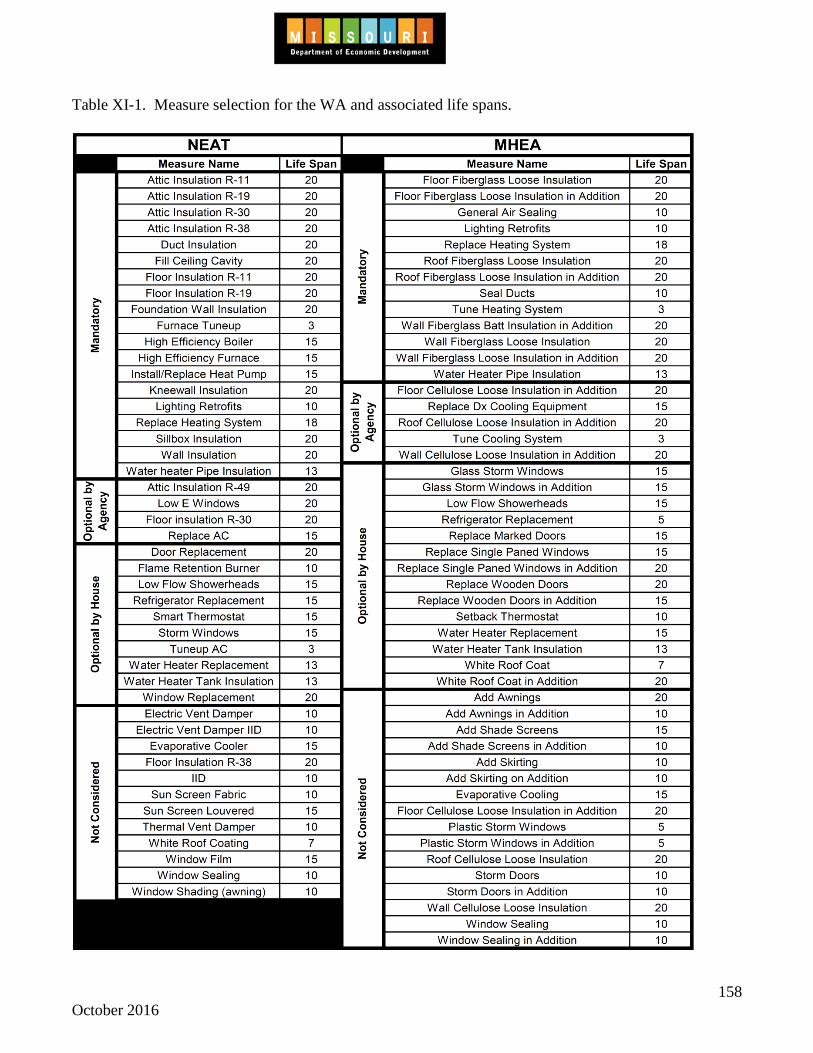
158 October 2016
Table XI-1. Measure selection for the WA and associated life spans.

159 October 2016
C. Performing a Computerized Audit on a Home Within the individual NEAT or MHEA audits, the information from each home is entered. Information entered into NEAT/MHEA needs to be done to accurately reflect the conditions of the home prior to weatherization Each subtopic below details a different tab in NEAT/MHEA and the necessary requirements associated with that tab. For any measures that the costs are not calculated by the Setup Library, the costs must include material and labor when being evaluated by the computerized audit. 1. General Information for tabs in NEAT/MHEA
a. General Information
Within NEAT/MHEA the boxes that have a black outline are the minimum boxes that must be completed on each tab in order to move forward and complete the computerized audit. The lone exception is in the ‘Ducts/Infiltration’ tab. All the information given in Section XI, Subsection C, Topic 6: Ducts/Infiltration Tab must be completed.
b. Help Menu
Within the Weatherization Assistant to pull up a help menu select a box and press F1 on the keyboard, this will bring up a help menu specific to the box that is selected.
c. Added or Additional Installation Cost
The computerized audit allows for the addition or subtraction of additional measure installation costs. The costs are in addition to the base cost of measures that are contained in the setup library. Whenever additional costs are added in the 'Additional Cost' box, a comment must be entered into the comment box on that tab to explain the necessity of the additional cost. As an example, consider the base cost of attic insulation, calculated at a certain price per square foot, would cost $350 for a particular attic. Additional installation cost might include cutting a new attic access, two vents, roofing tar and nails for a total of $150. When the additional installation costs are entered in the “Additional Cost” box for the measure, the audit internally combines the two costs and cost-tests the attic insulation measure at $500 rather than at $350.
d. Measure Numbers for Walls, Attics and Foundation Spaces
Measure numbers group together building components (walls, attics and foundation spaces) that are to receive the same energy conservation measure or for which a single SIR will be determined. For example, attic components that have the same measure number will receive an SIR and separate ranking from attic components having a

160 October 2016
different measure number. Building components having similar construction and existing insulation levels should have the same measure number assigned.
2. Audit Information Tab
a. Weather Data
Subgrantees must choose the appropriate weather data that most closely matches the weather for the subgrantee service area.
b. Conditioned Stories
(1) Enter the number of conditioned stories above grade. This is used to compute the
stack effect of infiltration in the computerized audit.
(2) Include the basement in the number of conditioned stories if the basement is heated or cooled and the majority of the basement wall area is above grade or the basement is a walk out basement.
c. Floor Area
Enter the number of square feet of floor area that is conditioned. The value entered is the total floor area, not the footprint area (e.g. enter 2400 for a two story house with 1200 square feet in each story).
3. Shell Tab
Within the ‘Shell’ tab the existing structural information will be entered. Refer to the help menu within the WA for information regarding the contents of the various boxes. See Section XI, Subsection C, Topic 1: General Information for tabs in NEAT/MHEA, for additional information regarding the help menu.
a. Walls
Enter the structural information for the walls of the house that are part of the thermal boundary. Walls that are not part of the thermal boundary should not be entered (e.g. exterior walls of an attached garage).
b. Windows
(1) Enter the structural information for the windows on the thermal boundary. Windows that are not on the thermal boundary should not be entered (e.g. windows on the exterior wall of an attached garage).
(2) The leakiness field allows the user to describe the air leakage characteristics of each
window. This leakiness factor describes the condition between the sash and frame of

161 October 2016
the window. NEAT and MHEA uses this factor to calculate the energy savings due to reduced air infiltration for window considered for replacement. Refer to Attachment 3.7: Window Leakiness Guidelines to ensure that the proper leakiness factor is selected for each window.
(3) Sliding glass doors should be entered into the computerized audit as a window. (4) The retrofit option of 'Evaluate All' should be used when evaluating window
replacement or storm window installation. The options of 'Replace' or 'Add Storm' should not be used unless DED/DE approval has been granted.
c. Doors
(1) Enter the structural information for the doors on the thermal boundary. Doors that are not on the thermal boundary should not be entered (e.g. doors on the exterior wall of an attached garage).
(2) The leakiness field allows the user to describe the air leakage characteristics of each
door. This leakiness factor describes the condition between the sash and frame of the door. NEAT and MHEA uses this factor to calculate the energy savings due to reduced air infiltration for doors considered for replacement. The leakiness factor selection should be based upon the following criteria: • Tight: Door is structurally sound, having functional weather stripping and door
sweep. • Medium: Door is in good to decent condition, may or may not have weather
stripping or a door sweep, but having limited to no leakage sites surrounding the door perimeter.
• Loose: Door is ill fitted, having noticeable leakage site surround the door perimeter with no weather stripping and possible structural problems.
(3) The evaluation of sliding glass doors for replacement, if necessary, should be done
under the window tab and not under the door tab. (4) The 'Replacement Door Required' box should not be checked when a replacement
door is being evaluated. Checking this box moves the measure up the priority list. (5) In MHEA, door replacements may be evaluated as part of the infiltration reduction
measure. In NEAT, door replacements may only be done if evaluated within the doors tab.
d. Unfinished Attics
Enter the structural information for all unfinished attics. The Added R Value field should only be used if only one specific amount of insulation should be evaluated for installation
162 October 2016
due to local jurisdiction. The Max Depth field should only be used if there is limited amount of depth of insulation that can be installed.
e. Finished Attics
Enter the structural information for all sections of finished attics. These sections are the outer ceiling joist, collar beam, kneewall and roof rafter. The outer ceiling joist is the section of the attic that is unfinished over the living space on the floor below. The collar beam is the flat section of the attic that is overhead when in the living space in the finished attic. The kneewall is the wall that separates the living space in the finished attic from the outer ceiling joist section. The roof rafter is the sloped or cathedral ceiling section of the finished attic.
f. Foundations
Enter the structural information for all foundations. This includes all basements and crawlspaces. The most common foundation types in Missouri are conditioned, non-conditioned, vented non-conditioned and uninsulated slab. For additional information regarding the determination of a foundation's thermal boundary, refer to Section IV, Subsection A, Topic 1: Preparation for Blower Door Test.
4. Heating Tab
a. All homes audited must have the heating system data entered into NEAT/MHEA to determine if the heating system can be replaced as an energy efficiency measure. Health and safety heating replacements need to be evaluated in NEAT/MHEA to account for the energy usage differential between the existing system and the replacement system. If a health and safety heating system replacement is determined to be necessary after work has started on the home, a rerun of the computerized audit is not required.
(1) The evaluated cost of replacement heating systems must include all associated costs.
These associated costs may range from gas shut off valves to additional ductwork. All of the costs must be included and the cost of the replacement heating system and associated costs must have a SIR of 1.0 or greater for the replacement heating system to be an ECM. (a) In the replacement system section in NEAT, evaluate all needs to be used for the
evaluation of replacement heating systems as a cost effective measure. (b) 'High Efficiency Replacement Mandatory' or 'Standard Efficiency Replacement
Mandatory' should only be selected if the heating system is otherwise required to be replaced due to health and safety reasons. The health and safety reason(s) for replacement must be documented in the client file if a mandatory replacement option is selected in the computerized audit.

163 October 2016
(2) There are some instances where, depending on circumstances, the heating system may be replaced either as a health and safety measure or an energy conservation measure. If the heating system has to be replaced as a health and safety measure it should be first evaluated in NEAT/MHEA to see if replacement is cost effective.
(3) When the heating system replacement is cost-effective, the measure will be treated as
a weatherization efficiency measure and the ‘Include in SIR’ box needs to be checked. For cost effective replacements, once the winning bid is received from the installing contractor for the installation of the heating system, the computerized audit must be re-run with the actual price of the bid to ensure the installation of the heating system is cost effective.
(4) The replacement of unvented gas space heaters must be evaluated as a health and
safety measure
b. Required information for the heating system must be entered on the main page of the NEAT heating tab and the Primary and Secondary tab of MHEA. All required information obtained during the combustion analysis test (Section III: Mechanical Systems and Combustion Appliances) must be entered into NEAT/MHEA with the values obtained during the test.
c. For gas and oil combustion heating systems, actual results from the combustion gas
analyzer for steady state efficiency (SSE) must be entered into NEAT/MHEA.
Exceptions:
(1) If an atmospherically drafting heating system is non-working or a combustion analysis could not be completed due to high CO, enter a SSE of 66 percent.
(2) If an induced draft heating system is non-working or a combustion analysis could not be completed due to high CO, enter a SSE of 76 percent.
(3) If a Category IV drafting heating system (high efficiency furnace or boiler) is non-working or a combustion analysis could not be completed due to high CO, enter a SSE of 86 percent.
(4) If the heating system is a gravity flow furnace (commonly referred to as octopus furnaces) or a gravity flow floor furnace then a SSE of 66 percent may be used to calculate SIR.
(5) If the heating system is a converted boiler system and the data plate is not readable or is not present, a SSE of 57 percent may be used in lieu of the values obtained during the combustion gas analysis.
(6) Existing unvented gas space heaters that are present during the initial audit that are used as a primary heating system will be entered as having a SSE of 100 percent.

164 October 2016
d. All electric heating systems will be entered as having a SSE of 100 percent, regardless if
the heating system is working or not.
e. Wood stoves and/or fireplaces that are primary heat systems should be entered as having a SSE of 50 percent.
f. The heating efficiency of an air source heat pump, also known as the Heating Seasonal
Performance Factor (HSPF), needs to be obtained either from manufacturer inscription on the existing unit or based off of the unit model information.
If the HSPF cannot be determined and documented, then the estimated age will need to be determined and the estimated HSPF will need to be entered into NEAT/MHEA. The calculations on how to determine the estimated HSPF based upon the age of the air source heat pump are as follows:
• 1970 and earlier: HSPF = 5.0 • 1971 to 2007: HSPF = 5.5 + 0.06875* (year manufactured - 1976) • 2008 and later: HSPF = 7.7
g. If a heating system is only used as a backup heat source, the heating system should not be
entered into the WA. Entering a backup heating system into the WA will result inaccurate energy modeling.
h. If a programmable (smart) thermostat is present, check the 'programmable thermostat'
box.
5. Cooling Tab
All homes audited with air conditioning, either central or window units, must have the cooling system data entered into NEAT/MHEA. The evaluated cost of replacement cooling systems must include all associated costs. All of the costs must be included and the cost of the replacement cooling system and associated costs must have a SIR of 1.0 or greater for the replacement cooling system to be an ECM.
a. The 'Replacement Required' box should not be checked unless a package unit heating and
cooling system is being replaced as outlined in Section XI, Subsection C, Topic 4, Subtopic a, Detail 1, Part b.
b. Non-working cooling systems should not be entered into the computerized audit. Only
working cooling systems may be evaluated for replacement as a cost effective measure. c. For cost effective replacements, once the winning bid is received from the installing
contractor for the installation of the cooling system, the computerized audit must be re-run with the actual price of the bid to ensure the installation of the cooling system is cost effective.

165 October 2016
d. The cooling capacity of the cooling system needs to be obtained on-site from the existing
unit.
e. The efficiency of the central air conditioner cooling system, also known as the Season Energy Efficiency Ratio (SEER), needs to be obtained either from manufacturer inscription on the existing unit or based off of the unit model information. If the efficiency of the unit cannot be determined and documented then the estimated efficiency of the cooling system shall be entered into the computerized audit. The estimated efficiency to be entered is found in Table XI-2. The SEER ratings in Table XI-2 are degraded based upon the NREL Building America Home Performance Analysis Procedures for Existing Homes. SEER is to be used for central systems, as well as room/window units in the computerized audit.
Table XI-2. Estimated SEER by year unit manufactured.
Year Unit Manufactured SEER Central System Room/Window Unit
1975 & earlier 4.3 4.5 1976-1980 4.6 4.8 1981-1991 6.3 6.4 1992-1999 8.5 9.3 2000-2008 11.2 10.2
2009 to present 14.0 11.1 6. Ducts/Infiltration Tab
When entering information into the Ducts/Infiltration Tab, the auditor must determine a target air infiltration reduction rate that will be achieved on the home. Determining the target air infiltration reduction rate is subjective and comes from experience and trial and error. Along with the target air infiltration reduction rate, the auditor must also determine how much it is going to cost to achieve that infiltration reduction. a. Once these numbers are determined and the audit is run, the computerized audit returns a
SIR for Infiltration Reduction. As long as the SIR is 1.0 or above, the infiltration reduction measure can be included in the work order. If the SIR is less than 1.0, then the auditor has two choices:
(1) Reduce the target air infiltration reduction rate and the cost to do the measure to see if
it will cost test. (2) Do not include infiltration reduction in the work order.
b. The actual initial audit blower door test result must be entered in the ‘Before
Weatherization (Existing)’ column. If a blower door test cannot be performed at a home, refer to Section IV, Subsection A: Blower Door Testing and Diagnostics for additional information.

166 October 2016
c. The target air infiltration reduction rate needs to be entered into the ‘After Weatherization (Target or Actual)’ column. The subgrantee is responsible for developing its own cost estimates and infiltration reduction targets based on historical data and on-site conditions to ensure reasonable accuracy of the NEAT/MHEA inputs. The target infiltration reduction and associated cost entered into NEAT/MHEA need to be comparable to the actual infiltration reduction and cost estimate when the home is completed.
d. Subgrantee staff needs to analyze actual air leakage reductions and costs to those
estimated during the NEAT/MHEA audit runs to see whether significant variations are occurring. This analysis will help identify where adjustments, in the future, may be needed.
7. Baseloads Tab
a. Water Heating
(1) If the home has a functioning water heater the water heater needs to be entered into NEAT/MHEA.
(a) If the water heater in a home is a tankless on-demand water heater, no water
heater should be entered into NEAT/MHEA. A note needs to be entered into the comment box that the home contains a tankless on-demand water heater.
(b) A water heater replacement with a SIR of 1.0 or greater is an allowable measure,
but standard water heater replacements are rarely cost effective. Tankless on-demand water heaters and heat pump water heaters may be evaluated for installation; however, DED/DE must be contacted regarding the evaluation of each tankless on-demand water heater or heat pump water heater that is evaluated as a replacement.
(c) If pipe wrap or a water heater blanket is not present but cannot be installed due to
on-site conditions or client refusal, the box indicating that a water heater wrap and/or pipe wrap is present should be checked and a comment put into the comment box stating that the wrap and/or pipe wrap could not be installed due to the specific circumstances.
(2) Existing showerhead information needs to be entered for evaluation of low flow
showerheads. The ‘Shower Use (min/day)’ is based on an average per shower time. Therefore, if there are two showers and each is used 30 minutes a day, then 30 minutes would be entered into the ‘Shower Use (min/day)’ box.
b. Refrigerators
Existing refrigerator and replacement refrigerator information needs to be entered for evaluation of refrigerator replacements. Refer to Section VII, Subsection B, Topic 1: Refrigerators/Freezers for additional information on metering refrigerators.

167 October 2016
c. Lighting Systems
Existing lighting and lighting retrofit information needs to be entered for evaluation of lighting retrofits. Lighting retrofits should only be evaluated for those lights which are used for an average of two hours a day or more. It is recommended that a burn time of no more than 4 hours be used for lighting replacements when assessed within the computerized audit.
8. Itemized Costs Tab
The following is a list of measures that can be entered into the “Itemized Costs” screen along with an explanation of how they are to be used in the Missouri Weatherization Assistance Program.
a. Health and Safety
Items entered as health and safety do not need to be cost tested and therefore the ‘include in SIR’ box should not be chosen for the measure within NEAT/MHEA. These items will appear at the bottom of the Recommended Measure List, and their cost will be added to the cumulative cost but not the cumulative SIR.
Measures listed below must be performed as a health and safety measure unless otherwise included in or considered as an energy conservation measure with an SIR of 1.0 or greater. Allowable health and safety measures include:
(1) Cleaning and tuning or replacing the heating system or cooling system when the SIR
is less than 1. Repairing or replacing combustion venting, heating equipment, cooling equipment, gas leaks, wiring, dryer vents or ventilation fans.
(2) Alleviating moisture-related problems or installing a vapor barrier (if no floor
insulation is installed). (3) Installing combustion air, carbon monoxide alarms, heat source barriers, or smoke
detectors. (4) Miscellaneous measures relevant to health and safety as defined in Section I,
Subsection A: Important Definitations.
b. Incidental Repairs
(1) If repairs must be done in order to preserve or protect the integrity of an eligible measure, the repair costs including material and labor must be included in the cumulative SIR calculation by checking the 'Include in SIR' box .
(2) No energy savings may be associated with incidental repairs
168 October 2016
(3) Repairs are limited to $600 in material per funding source or to the point where
NEAT or other approved computerized audit computes a cumulative SIR of not less than one (1), whichever comes first.
(4) Subgrantees may include the repair cost to protect the integrity of an individual
measure with that measure’s individual SIR calculation. (5) Refer to Section XII, Subsection D: Incidental Repairs for additional information on
incidental repairs.
c. Low Cost/No Cost Activities
Low-cost/no-cost activities must be included in the cumulative SIR of the home. On NEAT/MHEA the items will be entered as an Itemized Cost titled ‘LCNC’, have no annual energy savings entered onto the computerized audit and the ‘Include in SIR’ box must be checked.
d. User Defined Measures
This entry is used for an energy conservation weatherization activity that is not addressed by the within NEAT/MHEA. The energy savings for user defined measures are entered by the subgrantee. User defined measures can only be used on a case by case basis when approval is obtained from DED/DE.
D. Computerized Energy Audit Requirements
1. General Requirements
a. Each client file must have an accurate Recommended Measures generated by the computerized audit. One Recommended Measures with all of the energy efficiency measures installed on the home must be in the client file with the ‘Run On’ date being prior to the passing final inspection date.
b. The Recommended Measures must have been generated within six months of the home
being in progress. A home in progress does not include the hanging of smoke or carbon monoxide detectors. Refer to Section X, Subsection B, Topic 1 General Requirements for additional information regarding this requirement.
2. Savings to Investment Ratio (SIR)
a. Individual measure SIRs must be 1.0 or greater. Energy efficiency measures with a SIR of less than 1.0 are not allowable.
b. Subgrantees will not be reimbursed for any weatherization measure installed on a home
which does not have a SIR of 1.0 or greater. If a subgrantee has been reimbursed for a
169 October 2016
measure that did not have a SIR of 1.0 or greater, the subgrantee will be obligated to reimburse the funds for the measure. Reimbursement cost will include both material and labor.
c. Subgrantees may not use any funding source to "buy down" the cost of a measure to a
point where it has an SIR of 1.0 or greater except for in Multi-family buildings as outlined in Section IX, Subsection A, Topic 3: Expenditures/Funding Issues. DED/DE does not prohibit the installation of an entire weatherization measure with non-DED/DE administered funds.
3. Cumulative SIR
a. The cumulative SIR of the measures recommended by NEAT/MHEA must be 1 or
greater. The measures should be implemented in a descending order based on the priority of the NEAT/MHEA recommended measures. Subgrantees may set the SIR threshold above 1 for budget reasons, provided this threshold is applied consistently across all measures. When budget limits are a barrier, measures with a higher SIR, but lower Btu saving, may be omitted in favor of measures with a lower SIR that are estimated to save a significantly greater amount of Btu’s, provided each measure has an SIR of 1 or greater and the cumulative SIR remains at 1 or above. The criteria for the lower SIR substitution must be documented and maintained in the client file.
b. Should the estimated cumulative SIR compute to less than 1, the following options are
allowed:
(1) Remove the combination of cost effective weatherization measures and associated incidental repairs with the lowest individual measure SIR and rerun the audit to ensure that the cumulative SIR is 1 or greater. If the incidental repair was deemed necessary for the effective performance of the cost effective weatherization measure, then both the cost effective weatherization measure and the incidental repair must be removed in the attempt to meet the required cumulative SIR. This process would continue until the cumulative SIR of the home is 1.0 or greater.
(2) Reject the home for weatherization.
c. Subgrantees will not be reimbursed for any home which does not have a cumulative SIR
of 1.0 or greater. If the subgrantee has already been reimbursed for this home, the subgrantee will be obligated to reimburse the funds for the home. Reimbursement cost will include both material and labor.
4. Client File Documentation
Client files must contain a physical copy of the NEAT/MHEA Input Report and Recommended Measures. The ‘Run On’ date on the Recommended Measures and the latest date on the ‘Audit Status History’ on the Input Report must correlate.

170 October 2016
THIS PAGE IS INTENTIONALLY LEFT BLANK FOR FUTURE EXPANSION

171 October 2016
Section XII: Miscellaneous A. Prioritization of Weatherization Measures
1. All 'Mandatory' measures listed in Table XI-1must be evaluated for installation as outlined in Section XI, Subsection B, Topic 3: Library Measures Tab.
2. Any 'Option by Agency' measure listed in Table XI-1 may be evaluated for installation as
outlined in Section XI, Subsection B, Topic 3: Library Measures Tab. 3. Once evaluated measures are determined to be cost-effective by the computerized audit, the
measures should be installed based on cost-effective prioritization.
4. If it is determined at any time prior to the beginning of work on the home that for legitimate reasons an approved measure cannot be installed, the computerized audit must be re-run to remove the measure which could not be installed. Therefore, it is imperative that the initial auditor correctly evaluate the home so that measures which cannot be installed for legitimate reasons are not evaluated for installation.
5. If work has started on the home and it is determined that a measure is unable to be installed for legitimate reasons, all other weatherization measures should be installed and a comprehensive explanation of why the measure was skipped should be included in the client file. If a client declines a measure based on a legitimate health concern, alternate materials should be researched that can be used to complete the ECM and protect the client's health. If an alternative material cannot be found, the measure may be skipped and measures with a lower SIR may be installed. Be sure to document why the measure was not installed.
6. If subgrantee staff or contractors are not adequately trained or equipped to perform certain
measures, the measures cannot be skipped. When priority measures cannot be installed due to lack of trained staff or equipment, standard procedures should be to postpone the job until adequate training and/or equipment are acquired.
7. All Health and Safety measures should be installed prior to installing ECM's. The inability
to install health and safety measures will require the deferral of the home since a home cannot be considered complete without having ECM's installed.
8. A signed and dated, agency developed, Change Work Order must be included in the client
file whenever:
• an ECM, health and safety measure or incidental repair listed on the Recommended Measures is removed from the work scope, or
• an ECM, or health and safety measure that is not listed on the Recommended Measures is added to the work scope.
The Change Work Order must be signed by the QCI, Energy Auditor, Weatherization Director or other agency staff member who has authority to approve the change in the work
172 October 2016
scope. Verbal approval for work changes may be given but must be followed by completion of the change work order.
B. Work Order Review with Client
After the computerized audit has been completed and the work order has been developed, the subgrantee needs to review all measures to be installed with the client prior to any work being performed. This should include all energy efficiency measures, health and safety measures, incidental repairs and low-cost/no-cost activities.
C. Client Refusal of Material Installation Prioritization of energy saving measures is accomplished using generally accepted engineering methods and determined by the computerized audit. Allowing the refusal of a measure by a building owner or occupant does not comply with these methods.
1. If an ECM is declined, appropriate client education techniques will often eliminate the
client's concern. a. If the auditor deems the reason for declining the measure(s) as legitimate, the auditor
should complete all other weatherization measures and include in the client file a comprehensive explanation of the rationale for skipping the specific measure(s).
b. If the auditor deems the reason for declining the measure(s) is not a legitimate reason, the situation must be fully documented in the client file. The work would be completed with the installation of only measures having a SIR higher than the declined measure.
2. Health and safety measures cannot be declined or refused by a client. If health and safety
measures cannot be performed at the home, then the home needs to be deferred.
3. After the work has started on the home and due to scheduling, measures are installed with a lower priority and during the process of installation the client declines a higher priority measure, the job would be complete at the time of the client declining the higher priority measure. Only measures having a SIR higher than the declined measure may be installed, unless a lower priority measure has already been installed. Documentation must be provided in the client file, explaining the reasons why a lower priority measure was installed prior to a measure with a higher priority.
D. Incidental Repairs
Incidental repairs are those minor repairs necessary for the effective performance or preservation of energy conservation measures. All work associated with the direct installation of an energy conservation measure (ECM), or required for the ECM measure to comply with code, the SWS or DE standards must be included in the cost of the measure and cannot be considered an incidental repair.

173 October 2016
Examples: • Fixing a small roof leak, to protect attic insulation which is being installed, is eligible
since the repair is not completed to comply with code or the SWS, but for the preservation of the attic insulation.
• Minor repairs to a door jamb that are necessary to allow weather stripping to be installed can be considered an incidental repair tied to the weather stripping. However, repairing the door jamb without installing weather stripping would need to be an infiltration reduction measure.
• When installing a new furnace, the gas valve, drip leg, electric shutoff are all parts of the furnace installation and must be included for the furnace to comply with code; therefore, these components are NOT eligible as incidental repairs.
• When installing spray polyurethane foam (SPF), any thermal or ignition barrier (fire barrier) installed over the SPF to comply with code and/or the SWS, is NOT an eligible incidental repair.
• Repairing moderate size holes in the ceiling to keep insulation from falling to the floor while installing blown cellulose can be considered an incidental repair tied to the attic insulation. However, installing a sheetrock ceiling (more than four sheets) to contain or support the insulation being installed, is NOT a minor incidental repair. A complete ceiling necessary for the direct installation of the energy conservation measure may be beyond the scope of weatherization.
1. Incidental repairs must be justified in the client file with an explanation for their need and the
associated relationship to a specific ECM or group of ECM’s. Documentation of the incidental repair justification shall be done using Attachment 2.7: Incidental Repair Justification Form.
2. Incidental repairs shall be limited to $600 in combined materials and labor per funding
source distributed by DED/DE. Any incidental repairs to exceed this limit must have DED/DE approval prior to installing the incidental repair.
3. Installing a wall or ceiling surfaces, where there is not an existing surface, is not allowed as a
minor incidental repair or ECM. However, if an existing surface has become derelict (i.e. plaster falling off the ceiling, etc.) repairs requiring less than four sheets of drywall, or the equivalent, may be done as an infiltration reduction measure. Needing more than four sheets of drywall may be beyond the scope of weatherization.
4. Removing an overhead garage door and installing a wall is not allowed as an incidental
repair. 5. Incidental repairs must be limited to those minor repairs necessary for effective performance
or preservation of new energy conservation measures being installed by the subgrantee. Performing repairs that are only necessary to protect materials that existed in the building before weatherization is not allowed.
6. Additional repairs found to be necessary after the undertaking of a measure has commenced
should not be considered incidental repairs. The additional costs should be included as part

174 October 2016
of the cost of the measure. It would not be practical for a crew or contractor to stop work until the subgrantee has an opportunity to determine if adding the incidental repair costs would cause the home to, cumulatively, fall below cost-effectiveness.
7. See Section XI, Subsection C, Topic 8: Itemized Cost Tab and Attachment 1.4 Incidental
Repair Guidance Form for additional information on requirements for incidental repairs.
E. Low-Cost/No-Cost Activities The installation of low-cost/no-cost (LCNC) weatherization materials are allowable weatherization expenses. LCNC materials are inexpensive weatherization materials, such as water flow controllers, furnace filters or items which are considered to be cost effective, but are unable to be cost justified using the computerized audit. 1. A maximum of $50 per dwelling unit may be spent on materials to be installed as
low-cost/no-cost activities. 2. Low-cost/no-cost weatherization materials may not have any billed labor associated with the
installation of the material. 3. Materials installed may only be materials that cannot be evaluated using the computerized
audit, but are considered to be cost effective. See Table XI-1 for materials that may be evaluated using the computerized audit.
4 On the computerized audit, low-cost/no-cost activities must be included in the cumulative
SIR of the home. Refer to Section XI, Subsection C, Topic 8: Itemized Costs Tab, Subtopic C for information on entering LCNC's into the computerized audit.
5. All low-cost/no-cost materials must be recorded on the Incidental Repair Justification Form
(Attachment 2.7). Enter the material name in the ‘Incidental Measure’ box, enter low-cost/no-cost in the ‘Associated ECM(s)’ box and the ‘Justification for Tying to ECM(s)’ box is to be used to explain how the material is cost effective.
6. All low-cost/no-cost materials must be reported on MoWAP with a measure type of
Incidental Repair and ‘LCNC’ entered as the component. The cost for the low-cost/no-cost materials should not be entered as incidental repair costs under the funding source breakdown in MoWAP.
F. Material Standards
SWS Detail: 2.0702.1 Warranty and Service Agreement
1. Only weatherization materials that are listed in the most current Appendix A - Standards for Weatherization Materials in DOE 10 CFR Part 440, or that meet or exceed the standards prescribed in Appendix A, shall be installed as weatherization materials.
175 October 2016
Materials shall be installed according to state and local codes. Materials shall be installed according to manufacturers' instructions unless specified otherwise.
2. All weatherization measures installed need to be installed in such a fashion to stay in
place or remain intact for the duration of the lifespan of the measure, as evaluated in NEAT/MHEA.
3. Surfaces must be appropriately cleaned, prior to installing caulking or adhesive-backed
materials.
4. All exposed wood and raw edges, located either within the interior of the home or on the exterior of the home that have been installed or modified by WAP efforts shall have a primer or sealant applied in such a manner that the client can finish the wood to match surrounding wood surfaces. All finish coat paint used to cover primed or sealed surfaces should be supplied by the homeowner.
THIS REMAINDER OF THIS PAGE IS INTENTIONALLY LEFT BLANK FOR FUTURE EXPANSION

176 October 2016
THIS PAGE IS INTENTIONALLY LEFT BLANK FOR FUTURE EXPANSION

177 October 2016
Section XIII: Section 106 Requirements
Section 106 of the National Historic Preservation Act of 1966 stipulates that all federally funded projects be reviewed to take into account the effect the proposed project will have on any property that is included in, or eligible for inclusion in the National Register of Historic Places will require review, DED/DE has signed an Interagency Agreement with the Missouri State Historic Preservation Office (“SHPO”) (See Attachment 6.1). This policy will address operational changes to the Low-Income Weatherization Assistance Program that resulted from the agreement. Subgrantees are responsible for compliance with 36 CFR 800. Subgrantees may request advice, counsel or assistance from the State Historic Preservation Office or Division of Energy.
This policy is effective for all homes audited since February 11th, 2010.
Contact Information: Missouri Department of Economic Development State Historical Preservation Office 800-361-4827 / 573-751-7858 A. Programmatic Agreement Implementation
1. Training
At least one person employed with each weatherization agency must be trained and designated to carry out the stipulations of the Section 106 review process. This person must meet the Secretary of the Interior’s Professional Qualifications Standards (http://www.nps.gov/history/local-law/arch_stnds_9.htm) outlined in 36 CFR Part 61, Appendix A, or attend a minimum of one (1) Section 106 training session, provided by the State Historic Preservation Office. It is highly recommended that all weatherization auditors attend this training. If a Weatherization agency does not have an employee who meets the Secretary of the Interior’s Professional Qualification Standards, or has attended a Section 106 training session, then all homes must be submitted to the SHPO for Section 106 review.
2. Client File Requirements
The following is required to be included in all client files regardless of age of the home: Age of the home must be included on the client application for Weatherization Assistance
Program services. Photos of the home, including a streetscape photo. (See Attached 3-6.2) A map identifying the location of the property. If the project involves ground disturbing activity, the map must be a current USGS 7.5
minute topographical map. Free topographical maps can be printed from the website: http://www.ded.mo.gov/internetmapviewer/ or http://terraserver-usa.com/. o If the project does not involve ground disturbing activity, SHPO will allow the use of
simple location maps, (such as Google maps,) provided that the map shows cross streets, and the location of the property is marked.

178 October 2016
Projects that require the Section 106 review must have a completed Section 106 Project Information Form and all related applicable documents uploaded to the MoWAP client file.
3. Energy Audit Procedures
When performing an initial energy audit on a client’s home, the auditor must verify the estimated age of the home. Clear photos of the home, including a streetscape photo, must also be taken at this time. The age of the home and the photos must be included in the client files. While performing the initial energy audit, the auditor shall review the list of Measures Exempt from Further Review. (See Attachment 6.3) If the proposed activities are included on the list, no further action is necessary. If a proposed activity is not included on the list, the Subgrantee shall submit a completed Section 106 Project Information Form and all applicable documents to the SHPO for review. (See Attachment 6.4) The Section 106 review must be completed by the SHPO prior to the start of work on a project.
4. Emergency Situation Undertakings
All projects that require non-exempt energy efficient measures and involve health and safety emergencies as defined in Section II, Subsection B, Topics 4-6, can be completed in two phases. The Subgrantee may elect to perform individual emergency health and safety measures that are listed in Section XIII, Subsection C: Undertakings Exempt From Further Review in the initial phase of the project prior to approval from the SHPO. Prior to performing the second phase of the project, the Subgrantee must submit a Project Information Form and all applicable documents for the entire project, and await approval from the SHPO before commencing work.
B. Undertakings that Require Further Review
If a proposed activity is not included on the list of Measures Exempt from Further Review, or for projects involving ground disturbing activities, the Subgrantee shall submit a completed Section 106 Project Information Form and all applicable documents to the SHPO for review before commencing work. (See Attachment 6.4) When a project is determined by the SHPO to have an adverse effect on a historic property, and a resolution of the adverse effect is not readily achievable, the Subgrantee is responsible for issuing a public notice regarding the proposed project, in order to seek public comment. The public notice can be in any form of mass media; however, they shall not include the names of the property owners, and/or tenants. When requested, DED/DE and/or the SHPO shall assist the Subgrantee in identifying organizations interested in historic preservation in the local community, to seek input from the public on the proposed project to the extent possible. The Subgrantees shall notify DED/DE and the SHPO of members of the public or Tribes who have expressed interest in a project.

179 October 2016
At any time during the implementation of a project, should an objection be raised by a member of the public, the Subgrantee shall take the objection into account and consult as needed with the objecting party, DED/DE, the SHPO, or the ACHP to resolve the objection. In addition, when conditions dictate (for example, when writing a recordation report), Subgrantees must employ or contract with qualified professionals who at minimum meet the Secretary of the Interior’s Professional Qualifications Standards at 36 CFR Part 61 in the field of archaeology, history, architectural history, or other qualified preservation professional. The Subgrantee will make the professional’s resume and contract information available to DED/DE or the SHPO upon request.
C. Undertakings Exempt from Further Review 1. Categorical Exemptions
If the estimated age of the home is less than forty-five (45) years old, and does not meet the criteria established in the National Register Bulletin 22, Guidelines for Evaluating and Nominating Properties that Have Achieved Significance within the Past Fifty Years, no further action is necessary regarding the Section 106 review process. As required in A2, Client File Requirements, the estimated age of the structure, photographs, and a location map must be placed in the client file.
If the property is older than 45 years old, an alternative option for exemption is to conduct research at the SHPO to determine if the property has recently been reviewed. If the property has been reviewed by the SHPO within the last five (5) years from the date of application, and has been determined to be ineligible for inclusion in the National Register of Historic Places, the project may proceed without further review or consultation.
All weatherization materials included in Appendix A of 10 CFR 440, Standards For Weatherization Materials, excluding all windows and doors, are considered appropriate for use on historic properties, and do not require further review or consultation from the State Historic Preservation Office.
a. Specific Activities Exempt from Further Review
“Like-kind” replacement/repair is defined as a replacement action or repair that uses materials that match the original material in terms of composition, appearance, dimension, detailing and durability. To the extent practicable, original materials will be preserved and reused for like- kind replacement/repair.
(1) Exterior Rehabilitation
(a) Installation of scaffolding and other temporary construction-related structures
including barriers, screening, fences, protective walkways, signage, office trailers and restrooms.

180 October 2016
(b) Application of exterior paint on previously painted surfaces, including masonry.
(c) All lead paint abatement which does not involve removal or alteration of exterior features and/or a window’s surrounding casings sash components, trim and sills.
(d) Like-kind replacement/repair of:
• masonry foundations, floor joists, and ceiling joists • basement bulkhead doors • wood siding and trim • porch elements such as columns, flooring, floor joists, ceilings, railing,
balusters and balustrades, and lattice • roof cladding, flashing, gutters, soffits, and downspouts and with no change in
roof pitch or configuration • doors and door frames • window sash, frames, glazing and weather stripping (Replacement of existing
clear glass with new clear glass is allowed) • exterior vents
(e) Replacement/repair of: concrete foundations exterior heating, ventilation, and air conditioning (HVAC) mechanical units
that do not require any new venting or a new location, or venting is on the rear of the structure, not viewable from any public right of way
(f) Installation of:
• dryer vents, air intakes, and outlets on secondary facades • storm windows where the finish on the new storm window matches the finish
of the existing window in color. • caulk and expandable foam to prevent air infiltration so long as it is clear,
painted or colored to match the existing exterior materials • insulation on the underbelly of Mobile Homes • removable film on windows if the film is transparent • blown in insulation where no holes are drilled through exterior siding
(2) Interior Rehabilitation
(a) Interior improvements and rehabilitation where no structural alterations are made,
where no demolition of walls, ceilings and/or floors occurs, and where no drop ceilings are added or walls are furred out or moved, and consisting of:
plumbing work, including installation of water heaters electrical work, including improving lamp efficiency

181 October 2016
heating, ventilation, and air conditioning (HVAC) systems and their components
insulation installation in attics and crawl spaces blown in insulation where no decorative plaster is damaged replacement of interior doors where the size of the opening is not altered replacement or repair of door knobs and other door hardware.
(b) Like-kind replacement/repair of: plaster walls and ceilings floors, including refinishing
(c) Installation of drywall where original plaster wall surfaces are missing, and which
will not appreciably change the trim profile. No decorative plaster or other decorative features shall be covered.
(d) All painting and carpeting, provided that carpeting installation damages no
underlying wood or masonry floor surfaces. (e) All kitchen and bathroom remodeling provided no walls, windows, or doors are
altered. (f) All lead paint abatement which does not involve removal or alteration of interior
features. (g) All asbestos abatement which does not involve removal or alteration of interior
features.
(3) Equipment
Standard energy efficiency measures that do not require ground disturbance or relocation or removal of walls, ceilings or floors, such as, but not limited to: installation or replacement of motors, lighting, blowers, pumps, heating, ventilation, and air conditioning (HVAC) systems that do not require any new venting or a new location, or venting is on the rear of the structure, not viewable from any public right of way
D. Section 106 Compliance under Extraordinary Circumstances
1. Unanticipated Discoveries -If previously unidentified archaeological sites or historic
properties are discovered unexpectedly as a result of construction activities, the construction contractor will immediately halt all construction activity within a one-hundred (100) foot radius of the discovery, notify the Subgrantee of the discovery and implement interim measures to protect the discovery from looting and vandalism. Within forty-eight (48) hours of receipt of this notification of the discovery, the Subgrantee shall:
182 October 2016
a. inspect the work site to determine the extent of the discovery and ensure that construction activities have halted;
b. clearly mark the area of the discovery; c. implement additional measures, as appropriate, to protect the discovery from looting and
vandalism; and d. notify the SHPO, DED/DE and interested Indian Tribes or other parties of the discovery.
The Subgrantee will have seven (7) calendar days following notification to determine the National Register eligibility of the discovery after considering the timely filed views of the SHPO and interested Indian Tribes or other parties. The Subgrantee may assume the newly discovered property to be eligible for the National Register for the purposes of Section 106 pursuant to 36 CFR § 800.13(c). For properties determined eligible, the Subgrantee will notify the SHPO, DED/DE and interested Indian Tribes or other parties of those actions that it proposes to resolve adverse effects in a mitigation plan. • Consulting parties will have seven (7) calendar days to provide their views on the
proposed mitigation plan. • The Subgrantee will ensure that the recommendations of consulting parties are taken
into account to resolve adverse effects. • The Subgrantee will carry out the approved mitigation plan. The construction contractor will resume construction activities in the area of the discovery upon receipt of written authorization from the SHPO.
e. Discovery of Human remains - When an unmarked human burial or skeletal remains are
encountered during construction activities, the Subgrantee will comply with Missouri Rev. Stat. § 194.400, et seq. (Unmarked Human Burial Law).
Upon encountering unmarked human burials or skeletal remains during ground disturbing construction activities, the construction contractor will immediately stop work within a one-hundred (100) foot radius from the point of discovery and notify the Subgrantee. The construction contractor will implement interim measures to protect the discovery from vandalism and looting, but must not remove or otherwise disturb any human remains or other items in the immediate vicinity of the discovery.
Immediately following receipt of such notification, the Subgrantee will:
(1) Ensure that construction activities have halted within a one-hundred (100) foot radius
from the point of discovery.

183 October 2016
(2) Implement additional measures, as appropriate, to protect the discovery from looting and vandalism until the requirements of state law have been completed.
(3) Notify the local law enforcement officer, the SHPO, DED/DE and interested Indian
Tribes or other parties, of the discovery.
The investigation by the local law enforcement officer will establish jurisdiction over the remains. The Subgrantee will notify the SHPO when local law enforcement determines that the SHPO has jurisdiction. Within seven (7) days of receipt of such notification, the SHPO will determine the treatment to be implemented. If the human remains are Native American, the SHPO in consultation with interested Indian Tribes will determine the treatment to be implemented.
The construction contractor will resume construction activities in the area of the discovery upon receipt of written authorization from either local law enforcement or the SHPO, whoever has jurisdiction under state law.
THE REMAINDER OF THIS PAGE IS INTENTIONALLY LEFT BLANK FOR FUTURE EXPANSION

184 October 2016
THIS PAGE IS INTENTIONALLY LEFT BLANK FOR FUTURE EXPANSION

185 October 2016
Glossary AFUE Annual fuel utilization efficiency AHRI Air Conditioning, Heating, and Refrigeration Institute, www.ahrinet.org Air barrier The separation between the interior and exterior environments of a building that
slows air flow to the point that no smoke movement is visible at 50 pascals of pressure difference across the boundary
ANSI American National Standards Institute, www.ansi.org ASHRAE American Society of Heating, Refrigerating and Air-Conditioning Engineers,
www.ashrae.org Backdraft damper A damper that allows air to flow in only one direction Beaded collar A round fitting with a ridge or lip part way down its length that prevents a
flexible duct mechanically attached with a draw band from sliding off BPI Building Performance Institute, www.bpi.org BTU British thermal unit Can light A light fixture (or can) that is recessed into the ceiling Cathedral ceiling A condition in which the ceiling has the same slope as the roof Cathedralized attic An attic that contains insulation located at the roof deck rather than the attic
floor, bringing the attic space into the thermal boundary of the house CAZ Combustion appliance zone CFL Compact fluorescent lamp CFM Cubic feet per minute Closed crawl space A foundation without wall vents that uses air-sealed walls, ground and
foundation moisture control, and mechanical drying methods to control crawl space moisture Insulation may be located at the conditioned floor level or on the exterior walls Return pathways are not allowed from the crawl space to the living space CO Carbon monoxide Conditioned basement A below- or partially below-grade livable space with concrete or
finished floor that is intentionally heated or cooled Conditioned crawl space A foundation without wall vents that encloses an intentionally heated
and/or cooled space Insulation is located on the exterior walls Dense pack The process of installing loose-fill insulation to reduce air flow and perform to a
stated R-value DHW Domestic hot water Dielectric union A plumbing connection that separates two different materials and does not
allow them to chemically react and break down EERE Office of Energy Efficiency and Renewable Energy (DOE) Efflorescence Deposits of crystals or salts left attached to masonry materials after moisture has
evaporated off of the surface Egress window A window that people can escape through in an emergency Envelope The separation between the interior and exterior environments of a building that
includes a combination of air and thermal barrier EPA U.S. Environmental Protection Agency, www.epa.gov ERV Energy recovery ventilator

186 October 2016
Exfiltration The uncontrolled passage of inside air out of a building through unintended leaks in the building envelope
Exterior storm window An additional window assembly installed on the exterior of the main window
Finished attic An attic space that has been converted into an additional living space of the house GFCI Ground-fault circuit interrupter GPM Gallons per minute Hi-limit switch A protective electronic switch that keeps a burner from continuing to operate
and damage the appliance HRV Heat recovery ventilator HVAC Heating, ventilation, and air conditioning IAQ Indoor air quality IBC International Building Code IC Insulation contact ICC International Code Council Ignition barrier Any layer of material that protects another from catching fire due to heat or
spark Infiltration The uncontrolled passage of outside air into a building through unintended leaks in
the building envelope Interior storm window An additional window assembly installed on the interior of the main
window IWC Inches of water column Knee wall Any wall between the conditioned space and the attic LED Light-emitting diode MSDS Material Safety Data Sheet Orphaned water heater Condition when one smaller combustion appliance (e.g., water heater)
exists after being commonly vented with a larger appliance What remains is a larger exhaust flue or chimney than is necessary for the water heater OSHA U.S. Occupational Safety and Health Administration, www.osha.gov Perm rating The measurement of a material’s ability to allow the transfer of water vapor
through the material PPE Personal protective equipment Programmable thermostat A thermostat designed to adjust the temperature according to a
series of programmed settings that take effect at different times of the day psi Pounds per square inch Rigid material Drywall, oriented strand board, duct board, cardboard, or any other stiff product
that may support the load of insulation while serving as a durable air barrier Sealant foam One- or two-component polyurethane foam typically applied as a bead and used to
control air leakage as part of an air barrier system within the building envelope SHGC Solar heat gain coefficient SI Système International SPF Spray polyurethane foam SSE Steady state efficiency Standby loss Heat loss through the outer part of a water heater Energy that is used even when a device is turned off Storm door An additional door assembly that is installed on the exterior of the main door

187 October 2016
Strip heat A function of a heat pump that uses energy-intensive resistance heat to warm conditioned space when the heat pump is unable to satisfy the heating demand; also provides emergency heat backup for heat pumps
Support material Typically, wooden strips that provide support over holes greater than 24” in size for less rigid air barrier materials
T&TA Training and Technical Assistance Thermal boundary The separation between the interior and exterior environments of a building
that slows heat flow Thermal resistance The insulation or other building material that offers the primary barrier to
thermal transmittance R-value is a measurement of thermal resistance Tie band A strap, often made of nylon that mechanically squeezes a flexible duct to a fitting Must have a minimum performance temperature rating of 165° (per UL 181A-type test) and a
minimum tensile strength rating of 50 pounds UL Underwriters Laboratories Unconditioned basement A below- or partially below-grade livable space with concrete or
finished floor without intentional heating or cooling UV Ultraviolet Vapor barrier A material that retards the passage of water vapor and contains a perm rating of
less than 1 Vapor retarder A material that slows the passage of water vapor and contains a perm rating
above 1 Vaulted ceiling A condition where a non-horizontal ceiling has a different slope than the roof Vented crawl space A foundation that uses wall vents as a primary means to control moisture Insulation is located at the conditioned floor level above the crawl space VOC Volatile organic compound Wood/materials shrinkage A loss of dimension and weight as a result of drying the structure
and operating the building at lower relative humidity

Attachment 1.1
WEATHERIZATION PROGRAM NOTICE 08-4 EFFECTIVE DATE: March 3, 2008
SUBJECT: SPACE HEATER POLICY
PURPOSE: To update the policy relating to space heaters for the Low-Income Weatherization Assistance Program (Weatherization). This policy supersedes the previous space heater policy issued by memoranda on March 18, 1992.
SCOPE: The provisions of this guidance apply to all grantees applying for financial assistance under the Department of Energy (DOE) Weatherization Assistance Program. This policy applies to electric and gas- and liquid-fueled space heaters only. Wood-burning stoves are addressed in separate guidance, which will be updated at a later date and will likely be expanded to include coal-burning stoves. This policy applies to electric and gas- and liquid-fueled space heaters whether the appliance is the primary or secondary heat source.
LEGAL AUTHORITY : Title IV, Energy Conservation and Production Act, as amended, authorizes the Department of Energy to administer the Low-Income Weatherization Assistance Program. All grant awards made under this program shall comply with applicable law including regulations contained in 10 CFR Part 440 (most recently issued June 22, 2006), and other procedures applicable to this regulation as DOE may from time to time prescribe for the administration of financial assistance.
INTRODUCTION: An estimated three million low-income households in the United States rely on space heaters as their primary method of heating their homes. An additional four million low-income households use space heaters as a secondary method of heating. Potential health and safety risks associated with the use of space heaters, especially portable and unvented devices include elevated levels of carbon monoxide, fire hazards, and excessive moisture resulting in mold and rot.
The previous space heater policy was issued March 18, 1992. Since then, Weatherization providers have improved their ability to reduce air infiltration in weatherized dwellings, which can exacerbate carbon monoxide and moisture hazards. Within the past ten years, local jurisdictions in at least 48 and 44 States have adopted the International Residential Code (IRC) and International Fuel Gas Code (IFGC), respectively, that include requirements related to space heaters. Most of these States have adopted the codes and enforce them statewide. The space heater policy issued by this Weatherization Program Notice (WPN 08-4) is consistent with the IRC and IFGC and clarifies how to best address eligible dwelling units containing space heaters.
Weatherization Program Notice 08-4 2
INCIDENTAL REPAIRS: Incidental repairs under the Weatherization Program are not affected by the policy contained herein. Agencies may continue making incidental repairs necessary to allow weatherization work to proceed safely, including to space heaters. SPACE HEATER POLICY: Separate guidance is provided for vented space heaters and unvented space heaters. Vented Space Heaters: Vented gas- and liquid-fueled space heaters should be treated the same as furnaces in terms of repair and replacement, as well as combustion appliance safety testing. This policy applies to vented natural gas-fired space heaters, vented propane-fired space heaters, and oil-fired space heaters (which are always vented). Unvented Space Heaters: Separate guidance applies to electric space heaters and unvented gas- and liquid-fueled space heaters.
Electric Space Heaters – DOE will not permit any DOE-funded weatherization work other than incidental repairs on electric space heaters. DOE will not preclude the use of other funding sources for the replacement or major repair of electric space heaters, but the Department does not encourage it because of: • The high cost of electricity as compared to fossil fuels; • Lower output ratings (size); • Risk of fire hazards; and, • Inadequate electrical systems in older homes frequently cannot safely carry the
power required to operate an electric heater. Work on such systems may make local agencies liable for inadequate electric wiring and damages that may result. Unvented Gas- and Liquid-Fueled Space Heaters – DOE will not permit any DOE-funded weatherization work where the completed dwelling unit is heated with an unvented gas- and/or liquid-fueled space heater as the primary heat source. This policy applies to unvented natural gas-fired space heaters, unvented propane-fired space heaters, and unvented kerosene space heaters. This policy is consistent with the IRC and the IFGC. DOE strongly encourages removal of all unvented gas- and liquid-fueled space heaters and replacement with vented, code-compliant heating systems as a prerequisite to weatherization. However, DOE will allow unvented gas- or liquid-fueled space heaters to remain as secondary heat sources in single-family houses provided they comply with the IRC and the IFGC. DOE is allowing this flexibility primarily to provide low-income clients an emergency back-up source of heat in the event of electrical power outages. Therefore, preference should be given to code-compliant units that do not require electricity. Specifically, any unvented gas- and liquid-fueled space heaters that remain in a completed single-family house after weatherization:

Weatherization Program Notice 08-4 3
• Shall not have an input rating in excess of 40,000 Btu/hour;• Shall not be located in, or obtain combustion air from sleeping rooms, bathrooms,
toilet rooms, or storage closets, unless:o Where approved by the authority having jurisdiction, one listed wall-mounted
space heater in a bathroom:� Has an input rating that does not exceed 6,000 Btu/hour;� Is equipped with an oxygen-depletion sensing safety shut-off system; and� The bathroom meets required volume criteria to provide adequate
combustion air;o Where approved by the authority having jurisdiction, one listed wall-mounted
space heater in a bedroom:� Has an input rating that does not exceed 10,000 Btu/hour;� Is equipped with an oxygen-depletion sensing safety shut-off system; and� The bedroom meets required volume criteria to provide adequate
combustion air.• Shall require the enforcement of minimum ventilation guidelines as determined
by the greater of:o 15 cubic feet per minute (CFM) per person,o 15 CFM per bedroom plus one [(# of bedrooms + 1) x 15 CFM], oro .35 air changes per hour.
The above minimum ventilation guidelines are natural ventilation rates, not with the house depressurized to -50 Pascal with a blower door.
Alternately, the minimum ventilation guidelines in the American Society of Heating, Refrigeration, and Air-Conditioning Engineers (ASHRAE) Standard 62.2, Ventilation and Acceptable Indoor Air Quality in Low-Rise Residential Buildings, may be used if the State desires.
DOE funds may only be used to replace the primary heating source. DOE funds may not be used to replace unvented space heaters to be left in the weatherized dwelling unit as secondary heating sources. For example, a home has several older gas- or liquid-fueled, unvented space heaters that do not comply with the International Residential Code because they do not have oxygen-depletion sensing safety shut-off systems. The Weatherization Program can replace the primary unvented space heater with a vented unit, but cannot expend DOE funds to replace one of the existing secondary space heaters with a code-compliant unvented unit with an oxygen-depletion sensing safety shut-off system. DOE will not preclude the use of other funding sources to replace secondary space heaters with code-compliant units.
The Manufactured Home Construction and Safety Standards require all fuel-burning, heat-producing appliances in mobile homes, except ranges and ovens, to be vented to outside. Further, all fuel-burning appliances in mobile homes, except ranges, ovens, illuminating appliances, clothes dryers, solid fuel-burning fireplaces and solid fuel-burning fireplace stoves, must be installed to provide for the complete separation of the combustion system from the interior atmosphere of the manufactured home (i.e., to draw their combustion air from outside).

Weatherization Program Notice 08-4 4
Cost Effectiveness: Current regulations governing weatherization activities require that measures installed in a dwelling unit be selected on the basis of cost effectiveness, with the most cost effective installed first. Unvented space heaters have very high efficiency ratings because they discharge their exhaust gases directly into the space being heated rather than outside, allowing the energy embodied in the hot exhaust gases to be released into the heated space. Vented space heaters exhaust combustion products and considerable amounts of energy out of the residence, and, therefore, are far less energy efficient.
The replacement of an unvented space heater with a vented one may not be cost-justified through energy savings. However, DOE strongly encourages States to combine other weatherization measures and health and safety considerations with vented space heaters as replacements for unvented space heaters. In such instances, the heat energy demanded by the structure can be lowered by energy-saving, cost-effective weatherization measures so that total energy costs are less or the same, while the indoor air quality is greatly improved through the use of a vented space heater paid for with health and safety funds.
Smoke and Carbon Monoxide Detectors: Any space heater replacement or repair procedure should include inspection to ensure that working smoke and carbon monoxide detectors are installed on the same floor as the space heater. In instances where smoke and carbon monoxide detectors are not present or are not operating properly, new detectors may be purchased and installed with DOE funds. The purchase and installation cost of the smoke and carbon monoxide detectors may be charged to the health and safety category or to program operations at the State’s discretion.
Client Education: Client education, including information on the proper operation of the heating equipment and installed smoke or carbon monoxide detectors, should be provided. Of critical importance is strong client education regarding the dangers of carbon monoxide and excessive moisture levels, particularly if any unvented space heaters are left in the dwelling as a secondary heat source, or emergency back-up.
Other Heath and Safety Consideration: Electrical wiring and chimneys should be checked to ensure they are in good condition and that no obvious building code violations are evident. Masonry chimneys used by vented space heaters should be properly lined in compliance with the IFGC. Safety inspection related to the space heater should include, but not be limited to, a check for adequate floor protection and code-compliant clearances to walls and other combustible materials. Even though many vented space heaters are manufactured with spill switches, it is still a requirement that a worst-case depressurization draft test be performed on all vented units.
Compliance with Local Code, Permitting, and Inspection Requirements: Installation of space heaters requires knowledge of appropriate industry standards and adherence to all aspects of the applicable building code(s) in the municipality where installation is taking place. Building permits should be secured, where required, (this is a program operations cost) for all space heater work and final inspection by competent professionals should take place before any heater is put into operation. States are reminded that even licensed heating contractors may not be aware of the stringent requirements of the Weatherization Program, so their work should be reviewed by Program staff.
Weatherization Program Notice 08-4 5
IMPLEMENTATION: Grantee health and safety policy, especially as it relates to space heater repair and replacement, in compliance with the above guidance, must be explained in the applicable State plan or appropriate amendment in order to permit Project Management Center review and approval. Funds to address these items as part of weatherization work will be allowable costs. It is especially important to insure that adequate inspection, safety, liability, and insurance procedures exist and are followed. In all cases, an education component for clients should be a part of the space heater work. Further, testing for indoor air quality, especially carbon monoxide levels in homes with unvented space heaters, should be performed. The cost to purchase the testing device and mechanical tools necessary to check for indoor air quality and to train personnel to do the testing are allowable program expenses. These charges may be made to the program operations cost category. RELATED MATERIALS AND DOCUMENTS: The following pamphlets and fact sheets may be useful for educating clients and training staff. CONSUMER PRODUCT SAFETY COMMISSION PAMPHLETS (CPSC, http://www.cpsc.gov/cpscpub/pubs/pub_idx.html):
Smoke Detectors Can Save Your Life (English and Spanish versions) Carbon Monoxide Detectors Can Save Lives Carbon Monoxide Questions and Answers (English and Spanish versions) The Invisible Killer (CO) (English) The Senseless Killer (CO) (Spanish) What You Should Know About Space Heaters Product Safety Fact Sheet - No. 98: Electric Space Heaters Product Safety Fact Sheet - No. 97: Kerosene Space HeatersProduct Safety Fact
Sheet - No. 99: Ground-Fault Circuit Interrupter (GFCI) Product Safety Fact Sheet - No. 566: Home Fire Safety Checklist (English and
Spanish versions)
Ronald Shaw Acting Program Manager Office of Weatherization and Intergovernmental Program Energy Efficiency and Renewable Energy
Deleted: ¶

WEATHERIZATION PROGRAM NOTICE 11-6 EFFECTIVE DATE: January 12, 2011
SUBJECT: WEATHERIZATION HEALTH AND SAFETY GUIDANCE
PURPOSE: To update and provide clarification and additional information related to the implementation and installation of health and safety measures as part of the Department of Energy (DOE) Weatherization Assistance Program (WAP). This guidance also provides recommendations to Grantees as they develop their Health and Safety Plans and procedures. This Program Notice replaces Weatherization Program Notice 02-5 and related guidance, and in conjunction with other referenced guidance materials should be used when making decisions on how to address health and safety issues while conducting weatherization work. The information in this guidance as well as many additional health and safety resources related to weatherization are available on the Internet at www.waptac.org.
SCOPE: The provisions of this guidance apply to all Grantees applying for financial assistance under the DOE WAP.
LEGAL AUTHORITY: Title IV, Energy Conservation and Production Act, as amended, authorizes the Department of Energy to administer the Weatherization Assistance Program. All grant awards made under this Program shall comply with applicable law including regulations contained in 10 CFR Part 440, the Energy Policy Act of 2005, the Energy Independence and Security Act of 2007, the American Recovery and Reinvestment Act of 2009 (Recovery Act), and the Occupational Safety and Health Act of 1970 (29 USC §651), 29 CFR Part 1900, 1926, general industry and construction respectively.
BACKGROUND: Based upon DOE reviews and reports from Grantees, DOE determined that health and safety issues were being inconsistently addressed across the weatherization network. In order to create clarity and consistency in how health and safety issues are approached by Grantees, DOE reconvened its Health and Safety Committee to review current trends and practices for the health and safety concerns of the WAP network.
This Program Notice will assist Grantees in their development of a comprehensive approach to health and safety matters.

Weatherization Assistance Program 11-6 2
GUIDANCE: Over the years, a number of issues have been addressed to ensure that weatherization activities do not cause or exacerbate health and safety problems for workers and occupants. According to 10 CFR Part 440, allowable energy related health and safety actions are those actions necessary to maintain the physical well being of both the occupants and/or weatherization workers where:
• Costs are reasonable as determined by DOE in accordance with the Grantee’s approvedGrantee Plan; AND
• The actions must be taken to effectively perform weatherization work; OR• The actions are necessary as a result of weatherization work.
Two questions to ask here are:
1. What must we do within reasonable costs to get the home to a point we can go forwardwith weatherizing, where the weatherization work will be lasting and effective?
2. What must we do to ensure that the weatherization work we conducted does not create ahealth or safety problem for the occupant?
Health and safety measures are allowed where, cumulatively, they do not exceed reasonable costs, as approved by DOE, outlined in each Grantee’s approved Health and Safety Plan. DOE considers Grantees’ proposed Health and Safety Plans on a case-by-case basis and determines whether submitted costs are reasonable. Health and safety measures are allowed to be conducted only where energy efficiency measures are identified for installation. Grantees are required to identify health and safety procedures and the percentage of costs involved as a part of their overall Health and Safety Plan to be approved by DOE. This approach gives Grantees and Subgrantees the ability to incorporate new technologies and their costs into their programs by removing health and safety costs from the per-house limitation; if they are budgeted separately. In providing this approach, DOE encourages Grantees to be prudent in their oversight of the percentage of funds approved for health and safety mitigation on homes weatherized by their Subgrantees.
The regulations do not mandate a separate health and safety budget cost category, but rather encourages Grantees to budget health and safety costs as a separate category and, thereby, exclude such costs from the average per-unit cost calculation. This separate category also allows these costs to be isolated from energy efficiency costs in program evaluations. Grantees are reminded that, if health and safety costs are budgeted and reported under the program operations category, the related health and safety costs should be included in the calculation of the average cost per home and cost-justified through the audit.
Grantees should carefully consider the approach to be taken when they draft their health and safety procedures. While ease of accounting is an important consideration, Grantees should keep in mind that activities assigned to the health and safety budget category do not have to be cost justified by the energy audit. The same items assigned to incidental repair, weatherization material, or installation cost categories must be cost-justified.

Weatherization Assistance Program 11-6 3
There are some instances where, depending on circumstances, the measure can be considered either a health and safety measure OR an energy conservation measure (e.g., furnaces). In those instances where the measure has a cost-effective savings-to-investment ratio (SIR) of one (1) or greater, the measure should be treated as a weatherization efficiency measure1.
Deferral may be necessary if health and safety issues cannot be adequately addressed through this guidance. The decision to defer work in a dwelling is difficult but necessary in some cases. This does not mean that assistance will never be available, but that work must be postponed until the problems can be resolved and/or alternative sources of help are found. In the judgment of the auditor, any conditions that exist, which may endanger the health and/or safety of the workers or occupants, should be deferred until the conditions are corrected. Deferral may also be necessary where occupants are uncooperative, abusive, or threatening.
The following Health and Safety Guidance Table was developed within applicable legislation and DOE regulations. While not every possible health and safety issue is addressed herein, the guidance should provide enough relevant examples and direction to provide clarity to the many issues presented to DOE. The section following the Guidance Table provides direction on what must be addressed within the Grantee’s Approved Health and Safety Plan as part of their Grantee Plan.
Some common themes and requirements that should be considered when utilizing the Guidance Table are as follows:
• Where removal or replacement is addressed in the document, proper disposal is required,and allowed as a health and safety cost.
• Where hazards are identified, clients must be informed in writing and the document mustbe signed by the client and a copy maintained in the client file.
• State and local (or jurisdiction having authority) codes must be followed while installinghealth and safety measures.
• Workers must be qualified and adequately trained according to state and local (orjurisdiction having authority) codes specific to the work being conducted (electrical,plumbing, etc.).
• Where Actions/Allowability, Testing, Client Education, and Training are allowed orrequired, DOE funds may be used unless specified otherwise. Health and safetyexpenditure limits apply to the specific action being taken to address the health and safetyissue.
1 Any measures being considered as an efficiency measure that is not on the DOE‐approved priority list for the Grantee will require a site‐specific audit to be performed on the dwelling in order to justify the measure being installed as an efficiency measure.

Weatherization Assistance Program 11-6 4
Health and Safety Issue Action/Allowability Testing Client Education Training Air Conditioning and “Red tagged”, inoperable, or nonexistent heating Make sure systems are Discuss and provide Awareness of guidance. Heating Systems system replacement, repair, or installation is
allowed where climate conditions warrant, unless prevented by other guidance herein. Air conditioning system replacement, repair, or installation is allowed in homes of at-risk occupants where climate conditions warrant.
present, operable, and performing. Determine presence of at-risk occupants.
information on appropriate use and maintenance of units and proper disposal of bulk fuel tanks when not removed.
Appliances and Water Heaters
Replacement of water heaters is allowed on a case by case basis. Replacement and installation of other appliances are not allowable health and safety costs. Repair and cleaning are allowed. Also see Air Conditioning and Heating Systems and Combustion Gases.
Determine whether appliances/water heaters are performing safely. Combustion safety testing is required when combustion appliances are present.
Discuss and provide information on appropriate use, maintenance, and disposal of appliances/water heaters.
Awareness of guidance. Conducting diagnostic training.
Asbestos - in siding, walls, ceilings, etc
Removal of siding is allowed to perform energy conservation measures. All precautions must be taken not to damage siding. Asbestos siding should never be cut or drilled. Recommended, where possible, to insulate through home interior.
Inspect exterior wall surface and subsurface for asbestos siding prior to drilling or cutting.
Inform the client that suspected asbestos siding is present and how precautions will be taken.
Safe practices for siding removal and replacement. How to identify asbestos containing materials.
Asbestos - in vermiculite When vermiculite is present, unless testing determines otherwise, take precautionary measures as if it contains asbestos, such as not using blower door tests and utilizing personal air monitoring while in attics. Where blower door tests are performed, it is a best practice to perform pressurization instead of depressurization. Encapsulation by an appropriately trained asbestos control professional is allowed. Removal is not allowed.
Assess whether vermiculite is present. Asbestos Hazard Emergency Response Act of 1986 (AHERA) certified prescriptive sampling is allowed by a certified tester.
Clients should be instructed not to disturb suspected asbestos containing material. Provide asbestos safety information to the client. Formally notify client if test results are positive for asbestos and signed by the client.
Audit training on how to recognize vermiculite. AHERA course for testing. AHERA or other appropriately trained or certified asbestos control professional training for encapsulation.
Asbestos - on pipes, furnaces, other small covered surfaces
Assume asbestos is present in covering materials. Encapsulation is allowed by an AHERA asbestos control professional and should be conducted prior to blower door testing. Removal may be allowed by an AHERA asbestos control professional on a case by case basis.
AHERA testing is allowed a certified tester.
by Clients should be instructed not to disturb suspected asbestos containing material. Provide asbestos safety information to the client.
AHERA course for testing and asbestos control professional training for abatement. How to identify asbestos containing materials.
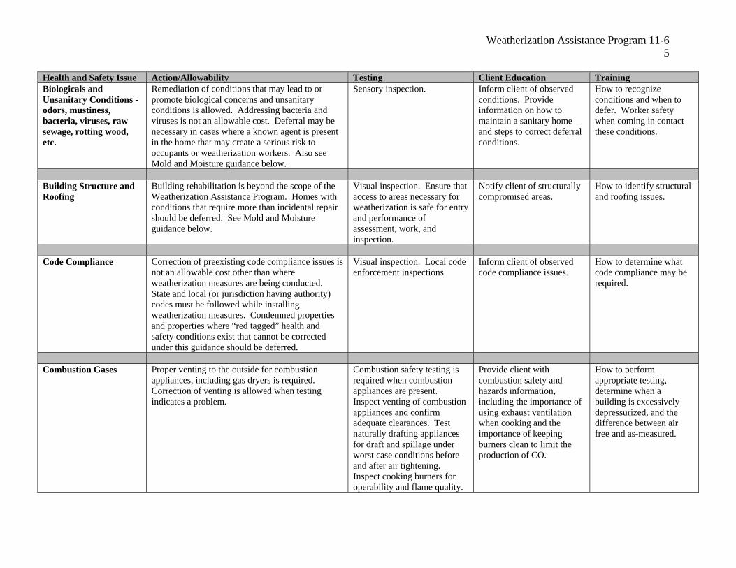
Weatherization Assistance Program 11-6 5
Health and Safety Issue Action/Allowability Testing Client Education Training Biologicals and Unsanitary Conditions - odors, mustiness, bacteria, viruses, raw sewage, rotting wood, etc.
Remediation of conditions that may lead to or promote biological concerns and unsanitary conditions is allowed. Addressing bacteria and viruses is not an allowable cost. Deferral may be necessary in cases where a known agent is present in the home that may create a serious risk to occupants or weatherization workers. Also see Mold and Moisture guidance below.
Sensory inspection. Inform client of observed conditions. Provide information on how to maintain a sanitary home and steps to correct deferral conditions.
How to recognize conditions and when to defer. Worker safety when coming in contact these conditions.
Building Structure and Roofing
Building rehabilitation is beyond the scope of the Weatherization Assistance Program. Homes with conditions that require more than incidental repair should be deferred. See Mold and Moisture guidance below.
Visual inspection. Ensure that access to areas necessary for weatherization is safe for entry and performance of assessment, work, and inspection.
Notify client of structurally compromised areas.
How to identify structural and roofing issues.
Code Compliance Correction of preexisting code compliance issues is not an allowable cost other than where weatherization measures are being conducted. State and local (or jurisdiction having authority) codes must be followed while installing weatherization measures. Condemned properties and properties where “red tagged” health and safety conditions exist that cannot be corrected under this guidance should be deferred.
Visual inspection. Local code enforcement inspections.
Inform client of observed code compliance issues.
How to determine what code compliance may be required.
Combustion Gases Proper venting to the outside for combustion appliances, including gas dryers is required. Correction of venting is allowed when testing indicates a problem.
Combustion safety testing is required when combustion appliances are present. Inspect venting of combustion appliances and confirm adequate clearances. Test naturally drafting appliances for draft and spillage under worst case conditions before and after air tightening. Inspect cooking burners for operability and flame quality.
Provide client with combustion safety and hazards information, including the importance of using exhaust ventilation when cooking and the importance of keeping burners clean to limit the production of CO.
How to perform appropriate testing, determine when a building is excessively depressurized, and the difference between air free and as-measured.
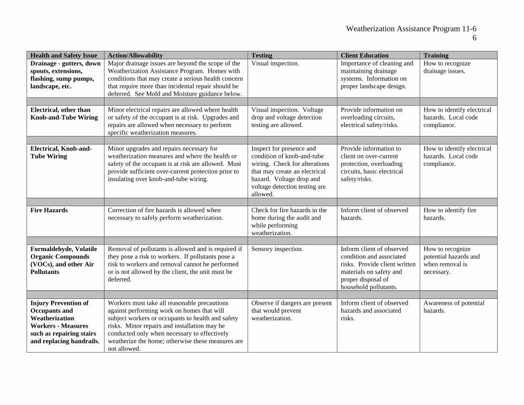
Weatherization Assistance Program 11-6 6
Health and Safety Issue Action/Allowability Testing Client Education Training Drainage - gutters, down spouts, extensions, flashing, sump pumps, landscape, etc.
Major drainage issues are beyond the scope of the Weatherization Assistance Program. Homes with conditions that may create a serious health concern that require more than incidental repair should be deferred. See Mold and Moisture guidance below.
Visual inspection. Importance of cleaning and maintaining drainage systems. Information on proper landscape design.
How to recognize drainage issues.
Electrical, other than Knob-and-Tube Wiring
Minor electrical repairs are allowed where health or safety of the occupant is at risk. Upgrades and repairs are allowed when necessary to perform specific weatherization measures.
Visual inspection. Voltage drop and voltage detection testing are allowed.
Provide information on overloading circuits, electrical safety/risks.
How to identify electrical hazards. Local code compliance.
Electrical, Knob-and-Tube Wiring
Minor upgrades and repairs necessary for weatherization measures and where the health or safety of the occupant is at risk are allowed. Must provide sufficient over-current protection prior to insulating over knob-and-tube wiring.
Inspect for presence and condition of knob-and-tube wiring. Check for alterations that may create an electrical hazard. Voltage drop and voltage detection testing are allowed.
Provide information to client on over-current protection, overloading circuits, basic electrical safety/risks.
How to identify electrical hazards. Local code compliance.
Fire Hazards Correction of fire hazards is allowed when necessary to safely perform weatherization.
Check for fire hazards in the home during the audit and while performing weatherization.
Inform client of observed hazards.
How to identify fire hazards.
Formaldehyde, Volatile Organic Compounds (VOCs), and other Air Pollutants
Removal of pollutants is allowed and is required if they pose a risk to workers. If pollutants pose a risk to workers and removal cannot be performed or is not allowed by the client, the unit must be deferred.
Sensory inspection. Inform client of observed condition and associated risks. Provide client written materials on safety and proper disposal of household pollutants.
How to recognize potential hazards and when removal is necessary.
Injury Prevention of Occupants and Weatherization Workers - Measures such as repairing stairs and replacing handrails.
Workers must take all reasonable precautions against performing work on homes that will subject workers or occupants to health and safety risks. Minor repairs and installation may be conducted only when necessary to effectively weatherize the home; otherwise these measures are not allowed.
Observe if dangers are present that would prevent weatherization.
Inform client of observed hazards and associated risks.
Awareness of potential hazards.
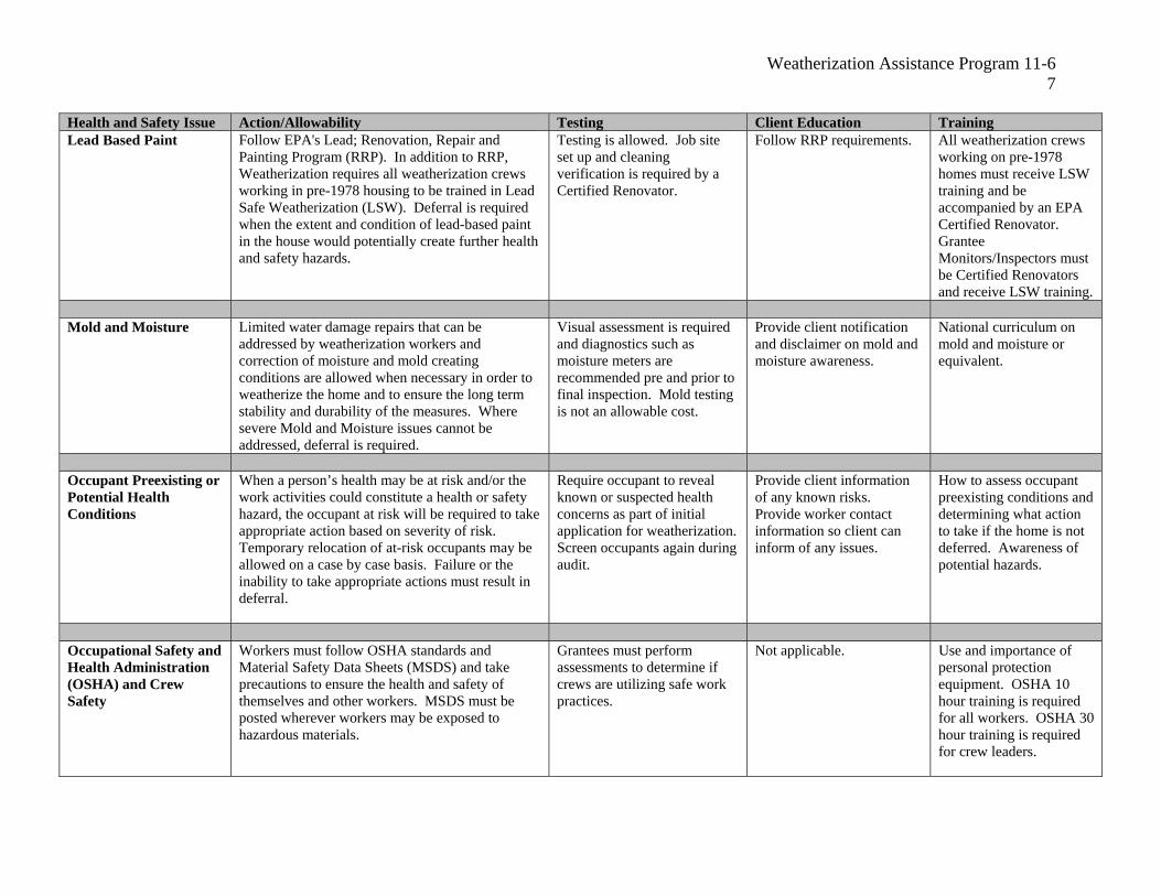
Weatherization Assistance Program 11-6 7
Health and Safety Issue Action/Allowability Testing Client Education Training Lead Based Paint Follow EPA's Lead; Renovation, Repair and
Painting Program (RRP). In addition to RRP, Weatherization requires all weatherization crews working in pre-1978 housing to be trained in Lead Safe Weatherization (LSW). Deferral is required when the extent and condition of lead-based paint in the house would potentially create further health and safety hazards.
Testing is allowed. Job site set up and cleaning verification is required by a Certified Renovator.
Follow RRP requirements. All weatherization crews working on pre-1978 homes must receive LSW training and be accompanied by an EPA Certified Renovator. Grantee Monitors/Inspectors must be Certified Renovators and receive LSW training.
Mold and Moisture Limited water damage repairs that can be addressed by weatherization workers and correction of moisture and mold creating conditions are allowed when necessary in order to weatherize the home and to ensure the long term stability and durability of the measures. Where severe Mold and Moisture issues cannot be addressed, deferral is required.
Visual assessment is required and diagnostics such as moisture meters are recommended pre and prior to final inspection. Mold testing is not an allowable cost.
Provide client notification and disclaimer on mold and moisture awareness.
National curriculum on mold and moisture or equivalent.
Occupant Preexisting or Potential Health Conditions
When a person’s health may be at risk and/or the work activities could constitute a health or safety hazard, the occupant at risk will be required to take appropriate action based on severity of risk. Temporary relocation of at-risk occupants may be allowed on a case by case basis. Failure or the inability to take appropriate actions must result in deferral.
Require occupant to reveal known or suspected health concerns as part of initial application for weatherization. Screen occupants again during audit.
Provide client information of any known risks. Provide worker contact information so client can inform of any issues.
How to assess occupant preexisting conditions and determining what action to take if the home is not deferred. Awareness of potential hazards.
Occupational Safety and Health Administration (OSHA) and Crew Safety
Workers must follow OSHA standards and Material Safety Data Sheets (MSDS) and take precautions to ensure the health and safety of themselves and other workers. MSDS must be posted wherever workers may be exposed to hazardous materials.
Grantees must perform assessments to determine if crews are utilizing safe work practices.
Not applicable. Use and importance of personal protection equipment. OSHA 10 hour training is required for all workers. OSHA 30 hour training is required for crew leaders.

Weatherization Assistance Program 11-6 8
Health and Safety Issue Action/Allowability Testing Client Education Training Pests Pest removal is allowed only where infestation Assessment of presence and Inform client of observed How to assess presence
would prevent weatherization. Infestation of pests degree of infestation and risk condition and associated and degree of infestation, may be cause for deferral where it cannot be to worker. risks. associated risks, and need reasonably removed or poses health and safety for deferral. concern for workers. Screening of windows and points of access is allowed to prevent intrusion.
Radon Whenever site conditions permit, exposed dirt Testing may be allowed in Provide client with EPA What is it, how it occurs. must be covered with a vapor barrier except for locations with high radon consumer’s guide to radon. What factors may make mobile homes. In homes where radon may be potential. radon worse. present, precautions should be taken to reduce the Weatherization measures likeliness of making radon issues worse. that may be helpful.
Vapor barrier installation.
Refrigerant Reclaim refrigerant per Clean Air Act 1990, EPA testing protocols. Clients should not disturb EPA-approved section section 608, as amended by 40 CFR82, 5/14/93. refrigerant. 608 type I or universal
certification.
Smoke, Carbon Installation of smoke/CO detectors is allowed Check for operation. Provide client with verbal Where to install detectors. Monoxide Detectors, where detectors are not present or are inoperable. and written information on Local code compliance. and Fire Extinguishers Replacement of operable smoke/CO detectors is use of smoke/CO detectors
not an allowable cost. Providing fire extinguishers and fire extinguishers where is allowed only when solid fuel is present. allowed.
Solid Fuel Heating Maintenance, repair, and replacement of primary Required inspection of Provide safety information How to perform CAZ (Wood Stoves, etc.) indoor heating units is allowed where occupant chimney and flue and including recognize depressurization test and
health and safety is a concern. Maintenance and combustion appliance zone depressurization. proper inspection. repair of secondary heating units is allowed. depressurization.
Space Heaters, Stand Repair, replacement, or installation is not allowed. Check circuitry to ensure Inform client of hazards and Awareness of guidance. Alone Electric Removal is recommended. adequate power supply for collect a signed waiver if
existing space heaters. removal is not allowed.
Space Heaters, Removal is required, except as secondary heat Testing for air-free carbon Inform client of dangers of How to perform air-free Unvented Combustion where the unit conforms to ANSI Z21.11.2. Units monoxide (CO) is allowed. unvented space heaters - CO testing.
that do not meet ANSI Z21.11.2 must be removed Check units for ANSI CO, moisture, NO2, CO can Understanding the prior to weatherization but may remain until a Z21.11.2 label. be dangerous even if CO dangers of unvented space replacement heating system is in place. alarm does not sound. heaters.
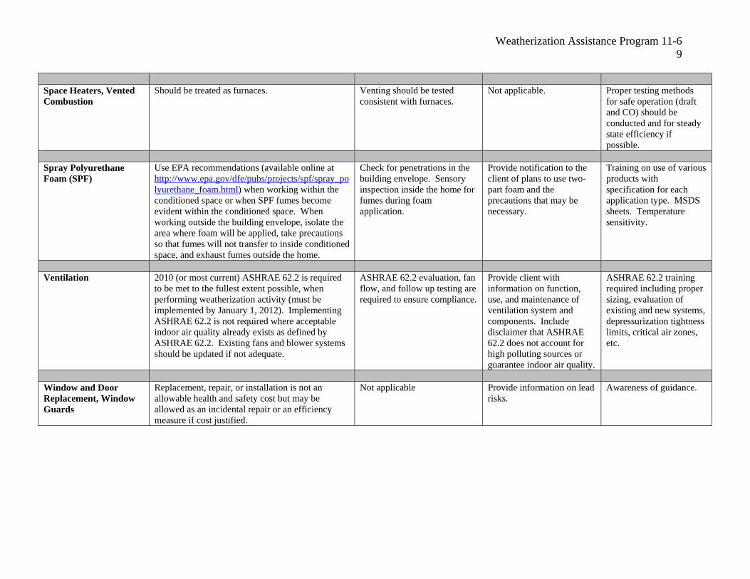
Weatherization Assistance Program 11-6 9
Health and Safety Issue Action/Allowability Testing Client Education Training Space Heaters, Vented Should be treated as furnaces. Venting should be tested Not applicable. Proper testing methods Combustion consistent with furnaces. for safe operation (draft
and CO) should be conducted and for steady state efficiency if possible.
Spray Polyurethane Use EPA recommendations (available online at Check for penetrations in the Provide notification to the Training on use of various Foam (SPF) http://www.epa.gov/dfe/pubs/projects/spf/spray_po building envelope. Sensory client of plans to use two- products with
lyurethane_foam.html) when working within the inspection inside the home for part foam and the specification for each conditioned space or when SPF fumes become fumes during foam precautions that may be application type. MSDS evident within the conditioned space. When application. necessary. sheets. Temperature working outside the building envelope, isolate the sensitivity. area where foam will be applied, take precautions so that fumes will not transfer to inside conditioned space, and exhaust fumes outside the home.
Ventilation 2010 (or most current) ASHRAE 62.2 is required ASHRAE 62.2 evaluation, fan Provide client with ASHRAE 62.2 training to be met to the fullest extent possible, when flow, and follow up testing are information on function, required including proper performing weatherization activity (must be required to ensure compliance. use, and maintenance of sizing, evaluation of implemented by January 1, 2012). Implementing ventilation system and existing and new systems, ASHRAE 62.2 is not required where acceptable components. Include depressurization tightness indoor air quality already exists as defined by disclaimer that ASHRAE limits, critical air zones, ASHRAE 62.2. Existing fans and blower systems 62.2 does not account for etc. should be updated if not adequate. high polluting sources or
guarantee indoor air quality.
Window and Door Replacement, repair, or installation is not an Not applicable Provide information on lead Awareness of guidance. Replacement, Window allowable health and safety cost but may be risks. Guards allowed as an incidental repair or an efficiency
measure if cost justified.

Weatherization Assistance Program 11-6 10
Grantee Health and Safety Plan Updates
All Grantees must amend their Health and Safety Plans in their master files of their Grantee Plan to be effective in Program Year 2011. Before any DOE funds can be expended for health and safety, Grantees must provide in the master file the hazards to be remedied and anticipated approaches including testing, training, client education, and conditions that require referral to other agencies that, therefore, necessitate a delay of weatherization services.
As a part of the Health and Safety Plan, Grantees must set health and safety expenditure limits for their Subgrantees, providing justification by explaining the basis for setting these limits and providing related historical experience. It is possible that these limits may vary depending upon conditions found in different geographical areas. These limits must be expressed as a percentage of the average cost per dwelling unit. For example, if the average cost per dwelling is $5000, 10 percent would equal an average of $500 per dwelling unit for health and safety. These funds are to be expended by subgrantees in direct weatherization activities.
At minimum, grantees must develop and include within their Health and Safety Plan, separate detailed components and explanations for:
• A system with guidelines for determining and documenting if the potential health andsafety issue should be remedied, referred to other agencies, result in partialweatherization, or lead to deferral. Subgrantees are expected to pursue reasonableoptions on behalf of the client, including referrals, and to use good judgment in dealingwith difficult situations. Documentation forms must be developed and should include theclient's name and address, dates of the audit/assessment and when the client wasinformed, a clear description of the problem, conditions under which weatherizationcould continue, the responsibility of all parties involved, and the client(s) signature(s)indicating that they understand and have been informed of their rights and options.
• Procedures that include a method used to determine when DOE monies will be used toremedy the health and safety issue, and how the Grantee will treat problems that cannotbe remedied with DOE monies after discovery.
• How training will be provided in order to meet the requirements of the health and safetyissues.
• Testing for the presence of health and safety issues, including, at a minimum, those testsrequired in the above Guidance Table.
• Implementation of ASHRAE 62.2, which will be required one year after the date thisguidance becomes effective. Grantees must provide justification if making changes toAHRAE 62.2 specific to their housing stock and local considerations in their GranteePlan.
• Implementation of Smoke/CO Detector installation parameters and procedures.• Implementation protocols on Air Conditioning and Heating System installation and repair
including justification for allowability that includes degree days for cold weather and hotweather climates, and how to define at-risk occupants.

Weatherization Assistance Program 11-6 11
• Detailed procedures on how the Grantee will handle problems discovered during testingof Combustion Gases.
• Implementation of OSHA and MSDS requirements related to crew and worker safety,how the 10 and 30 hour training requirements will be met, and what the process is fordetermining if crews are utilizing good safe work practices according to all requirements(EPA, OSHA, etc.).
• Protocols for addressing mold found in the client’s homes. The protocol should include amethod of identifying the presence of mold during the initial audit or assessment,notification to the client, and crew training on how to alleviate mold and moistureconditions in homes.
• Implement and verification of compliance with RRP and LSW.• Developing procedures and protocols for informing clients of hazards that are identified
during weatherization. Clients must be informed in writing and the document must besigned by the client and a copy maintained in the client file.
• Developing procedures for requiring clients to reveal known or suspected occupant healthconcerns as part of the initial application for weatherization, additional screening ofoccupants again during the audit, and how steps will be taken to ensure thatweatherization work will not worsen the health concern.
CONCLUSION: The Weatherization Assistance Program continues to make progress in addressing health and safety issues and ensuring the health and safety of weatherization workers and recipients of weatherization services. In addition to this guidance, DOE will continuously update and provide best practices and referral opportunities on the Internet at www.waptac.org.
LeAnn M. Oliver Program ManagerOffice of Weatherization and Intergovernmental Program Energy Efficiency and Renewable Energy
WEATHERIZATION PROGRAM NOTICE 11-6a EFFECTIVE DATE: April 28, 2011
SUBJECT: SUPPLEMENTAL WEATHERIZATION HEALTH AND SAFETY GUIDANCE
PURPOSE: To update and provide additional time for implementation of Weatherization Program Notice (WPN) 11-6 as part of the Department of Energy (DOE) Weatherization Assistance Program (WAP). This guidance also provides direction to Grantees as they develop their Health and Safety Plans and procedures. The information in this guidance as well as many additional health and safety resources related to weatherization are available at www.waptac.org.
SCOPE: The provisions of this guidance pertain to all Grantees applying for financial assistance under DOE WAP.
LEGAL AUTHORITY: Title IV, Energy Conservation and Production Act, as amended, authorizes DOE to administer the WAP. All grant awards made under WAP shall comply with applicable law including regulations contained in 10 CFR Part 440, the Energy Policy Act of 2005, the Energy Independence and Security Act of 2007, the American Recovery and Reinvestment Act of 2009 (Recovery Act).
BACKGROUND: DOE issued updated Health and Safety Guidance on January 12, 2011 to provide clarity and consistency in how health and safety issues are addressed in Weatherization. This Guidance document provides additional guidance from the DOE Health and Safety Committee to address health and safety issues raised by the WAP network.
GUIDANCE: While the components outlined in WPN 11-6 must be addressed in the 2011 Grantee Health and Safety Plans as part of the Grantee Plans (as outlined below), DOE has determined that in order to avoid undue hardship on any Grantee or to cause delays in their Application review process; Grantees may use the 2011 Program Year to implement the various applicable components of WPN 11-6. This extension provides the necessary time for Grantees to conduct research, solicit public input, and conduct any training necessary to effectively implement and enforce their Health and Safety Plans. It is still required that Grantees are in full compliance with WPN 11-6 in their 2012 Plan submissions.
Weatherization Assistance Program 11-6a 2
Special Note: While the majority of the WPN 11-6 Guidance allows for flexibility in Grantee policy and application, continuing activities that are expressly restricted in WPN 11-6 must be addressed in the 2011 Grantee’s Health and Safety Plans and enforced immediately. The restricted use of DOE funds for health and safety activities include:
• Actions that are unreasonable in cost as determined by DOE in accordance withthe Grantee’s approved Grantee Plan.
• Actions that are either not necessary to effectively perform weatherization work,where the work will be lasting and effective; OR are not necessary as a result ofweatherization work so as not to create a health or safety problem for theoccupant.
• Activities that are conducted where no efficiency measures are identified forinstallation.
• Installing health and safety measures that could have otherwise achieved a cost-effective savings-to-investment ratio and been treated as a weatherizationefficiency measure.
• Performing work in homes that should have been deferred in accordance with theGrantee Plan.
• Performing work by an untrained worker where a trained professional is required.• Replacement and installation of appliances other than water heaters.• Removal of asbestos, unless on small covered surfaces.• Addressing bacteria and viruses.• Correction of preexisting code compliance issues other than where weatherization
measures are being conducted.• Conducting mold testing.• Replacement of operable smoke/CO alarms, unless required by code compliance.• Window and door replacement, repair, or installation.
In the 2011 Program Year, DOE will provide additional assistance to Grantees with their Health and Safety Plan development. DOE will review Grantee Plans based on the revised guidance as a tool to help Grantees move toward compliance. Grantees must submit 2011 plans in accordance to normal Program Year schedules and must demonstrate movement toward 2012 implementation of WPN 11-6 strategies and requirements. It is assumed that some Grantees must still improve their capacity to address specific health and safety issues. Grantees are encouraged to provide as much detail as possible in their Plans and include a statement for those standards not yet ready for implementation but planned to begin in the 2012 Program Year. In the interim, Grantee’s should perform the following:
1. Update portions of the Health and Safety Plan that are ready for Grantee implementationand enforcement, while removing any conflicts with WPN 11-6.
2. Include those portions of the Health and Safety Plan that may not be ready forimplementation with a statement that the specific items are in place for DOE review.
Weatherization Assistance Program 11-6a 3
3. Include strategies that will be used to finalize that portion of the Plan for futureimplementation, no later than the beginning of the 2012 Program Year.
4. Submit revised Health and Safety Plan as part of the 2011 Grantee Plan.5. Full implementation and enforcement of WPN 11-6 by the Grantee must begin in the
2012 Program Year.
Project Officers will review and approve Grantee Plans for compliance with WPN 11-6 using standard procedures. Any conflicts with WPN 11-6 will be noted and resolved prior to approval. DOE will provide support materials, such as best practice documents and frequently asked questions, on its web site to help guide Grantees in formulating their Health and Safety Plans.
CONCLUSION: The Weatherization Assistance Program continues to make progress in addressing health and safety issues and ensuring the health and safety of weatherization workers and the families who receive the Weatherization services. In addition to this guidance, DOE will continuously update and provide best practices and referral opportunities at www.waptac.org.
LeAnn M. Oliver Program ManagerOffice of Weatherization and Intergovernmental Program Energy Efficiency and Renewable Energy


Weatherization Program Notice 12-09
5
GUIDANCE: The primary goal of the WAP is to lower the home energy costs of
qualified households without negatively affecting the health and safety of the occupants.
Justification for the cost of each IRM and how each IRM is necessary for the effective
performance or preservation of an ECM must be documented in the client file. Further,
each ECM, including any associated ancillary items and installation costs, must have a
calculated SIR of 1.0 or greater to be eligible for DOE funding. For each weatherized
building, the cost of the total package of ECMs, added to the cost of all IRMs for the
building, must have a calculated SIR of 1.0 or greater.
After the first audit run, a package of measures may not have a qualifying SIR. It would
be necessary to remove the combination of the ECM and its related IRM with the lowest
SIR. If the IRM was deemed necessary for effective performance of the ECM, then both
the ECM and the IRM must be removed in the attempt to meet the dwelling SIR. This
process (removing the lowest ECM and its associated IRM) would continue until the
package of measures (and each ECM) has a qualifying SIR.
If one IRM is necessary to protect or enhance more than one ECM, (e.g. roof repair
protecting attic insulation, sidewall insulation, and foundation insulation; and the Grantee
plan designates roof repair as an incidental repair) then all of those ECMs together must
be considered for removal until the SIR for the package of measures is 1.0 or greater.
This process may result in deferral of the weatherization work until another funding
source can be found to pay for the IRM(s).
IRMs must be limited to those minor repairs necessary for effective performance or
preservation of measures installed by the Subgrantee. WAP funds cannot be used to
install IRMs deemed necessary to protect materials in the building before the WAP audit
is performed.
A cost limit for per unit IRMs must be included in the cost of the audits submitted for
approval of a priority list. If a subsequent audit determines more extensive IRMs are
needed in a building, a full computerized energy audit must be run on the building to
justify additional IRM cost.
Grantees that use priority lists must set cost limitations in their annual plan for
IRM or perform a site specific audit to justify the cost of the incidental repairs.
Any Grantee policy or procedure dealing with IRM that does not comply with this
program notice, must be reviewed and revised as necessary to reflect the changes in
this guidance. If IRM costs are not limited, all previously approved priority lists
must be amended. Effective immediately, all Grantees should begin the process of
implementing this guidance with their Project Officer with all necessary actions
completed prior to the beginning of Program Year 2013, when full compliance will
be required.
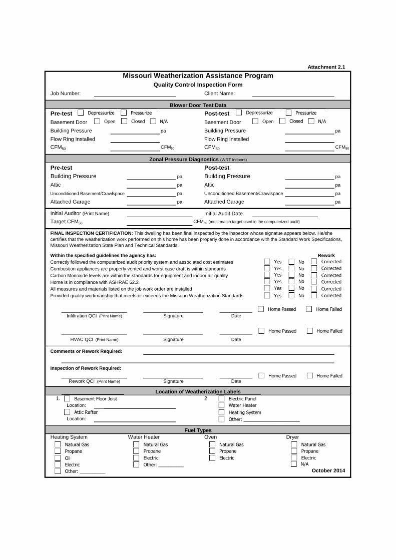
Pre-test Post-testBasement Door Basement Door
Building Pressure pa Building Pressure pa
Flow Ring Installed Flow Ring Installed
CFM50 CFM50 CFM50 CFM50
Pre-test Post-testBuilding Pressure pa Building Pressure pa
Attic pa Attic pa
pa pa
Attached Garage pa Attached Garage pa
Initial Auditor (Print Name) Initial Audit Date
Target CFM50 CFM50 (must match target used in the computerized audit)
Within the specified guidelines the agency has:
Comments or Rework Required:
Inspection of Rework Required:
1. 2.Location:
Location:
Heating System Water Heater Oven Dryer
October 2014
Location of Weatherization Labels
Fuel Types
Rework QCI (Print Name) Signature Date
HVAC QCI (Print Name) Signature Date
Infiltration QCI (Print Name) Signature Date
Provided quality workmanship that meets or exceeds the Missouri Weatherization Standards
FINAL INSPECTION CERTIFICATION: This dwelling has been final inspected by the inspector whose signatue appears below. He/she certifies that the weatherization work performed on this home has been properly done in accordance with the Standard Work Specifications, Missouri Weatherization State Plan and Technical Standards.
ReworkCorrectly followed the computerized audit priority system and associated cost estimatesCombustion appliances are properly vented and worst case draft is within standardsCarbon Monoxide levels are within the standards for equipment and indoor air qualityHome is in compliance with ASHRAE 62.2All measures and materials listed on the job work order are installed
Unconditioned Basement/Crawlspace Unconditioned Basement/Crawlspace
Blower Door Test Data
Zonal Pressure Diagnostics (WRT Indoors)
Attachment 2.1
Missouri Weatherization Assistance ProgramQuality Control Inspection Form
Job Number: Client Name:
Depressurize Pressurize
NoYes
Home Passed Home Failed
Basement Floor Joist
Attic Rafter
Electric Panel
Water Heater
Heating System
Home Passed Home Failed
Open Closed N/A
Corrected
Depressurize Pressurize
Open Closed N/A
Corrected
Corrected
Corrected
Corrected
Yes
Yes
Yes
Yes
No
No
No
No
Yes
Corrected
No
Other: ______________________
Natural Gas
Propane
Oil
Electric
Other: __________
Natural Gas
Propane
Electric
Natural Gas
Propane
Electric
Other: __________
Natural Gas
Propane
Electric
Home Passed Home Failed
N/A
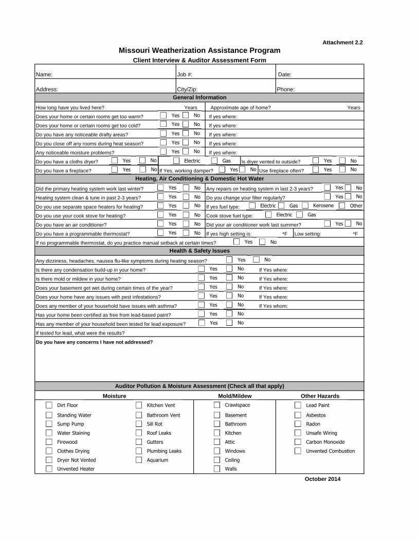
Job #: Date:
Years
If yes high setting is: *F Low setting: *F
October 2014
Did your air conditioner work last summer?
Auditor Pollution & Moisture Assessment (Check all that apply)
Moisture Mold/Mildew Other Hazards
Has your home been certified as free from lead-based paint?
Has any member of your household been tested for lead exposure?
If tested for lead, what were the results?
Do you have any concerns I have not addressed?
Does your home have any issues with pest infestations? If Yes where:
Does any member of your household have issues with asthma? If Yes whom:
Is there mold or mildew in your home? If Yes where:
Does your basement get wet during certain times of the year? If Yes where:
Do you have a programmable thermostat?
If no programmable thermostat, do you practice manual setback at certain times?
Health & Safety Issues
Any dizziness, headaches, nausea flu-like symptoms during heating season?
Is there any condensation build-up in your home? If Yes where:
Heating system clean & tune in past 2-3 years? Do you change your filter regularly?
Do you use separate space heaters for heating? If yes fuel type:
Do you use your cook stove for heating? Cook stove fuel type:
Do you have a fireplace? If Yes, working damper? Use fireplace often?
Heating, Air Conditioning & Domestic Hot Water
Did the primary heating system work last winter? Any repairs on heating system in last 2-3 years?
Any noticeable moisture problems? If yes where:
Do you have a cloths dryer? Is dryer vented to outside?
Do you have any noticeable drafty areas? If yes where:
Do you close off any rooms during heat season? If yes where:
Does your home or certain rooms get too warm? If yes where:
Does your home or certain rooms get too cold? If yes where:
Do you have an air conditioner?
Attachment 2.2
Missouri Weatherization Assistance ProgramClient Interview & Auditor Assessment Form
Name:
General Information
How long have you lived here? Years Approximate age of home?
Address: City/Zip: Phone:
Electric Gas
Electric Gas Kerosene Other
Electric Gas
Dirt Floor
Standing Water
Sump Pump
Water Staining
Firewood
Clothes Drying
Dryer Not Vented
Unvented Heater
Kitchen Vent
Bathroom Vent
Sill Rot
Roof Leaks
Gutters
Plumbing Leaks
Aquarium
Crawlspace
Basement
Bathroom
Kitchen
Attic
Windows
Ceiling
Walls
Lead Paint
Asbestos
Radon
Unsafe Wiring
Carbon Monoxide
Unvented Combustion
No
No
No
No
No
No
No No
No
No
Yes
Yes
Yes
Yes
Yes
Yes
Yes Yes
Yes
Yes
Yes
Yes
Yes
Yes
Yes
Yes
Yes
Yes
No
No
No
No
No
No
No
No
Yes
Yes
Yes
Yes
Yes
Yes No
No
No
No
No
No
Yes No
Yes No
Yes No Yes No
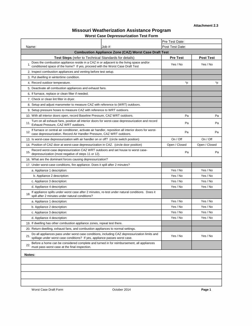
Pre Test Date:
Post Test Date:
1.
2.
3.
4. oF oF
5.
6.
7.
8.
9.
10. Pa Pa
11. Pa Pa
12. Pa Pa
13.
14.
15. Pa Pa
16.
17.
a. Appliance 1 description:
18.
a. Appliance 1 description:
b. Appliance 2 description:
c. Appliance 3 description:
d. Appliance 4 description:
19.
20.
21.
22.
Worst Case Draft Form October 2014 Page 1
Before a home can be considered complete and turned in for reimbursement, all appliances must pass worst case at the final inspection.
Notes:
Return dwelling, exhaust fans, and combustion appliances to normal settings.
Do all appliances pass under worst case conditions, including CAZ depressurization limits and spillage under worst case conditions? If yes, appliance passes worst case.
Yes / No Yes / No
Yes / No Yes / No
If dwelling has other combustion appliance zones, repeat test there.
Yes / No Yes / No
Yes / No Yes / No
d. Appliance 4 description: Yes / No Yes / No
If appliance spills under worst case after 2 minutes, re-test under natural conditions. Does it spill after 2 minutes under natural conditions?
Yes / No Yes / No
b. Appliance 2 description: Yes / No Yes / No
c. Appliance 3 description: Yes / No Yes / No
What are the dominant forces causing depressurization?
Under worst-case conditions, fire appliance. Does it spill after 2 minutes?
Yes / No Yes / No
Is worst-case depressurization with air handler on or off? (circle switch position) On / Off On / Off
Record worst-case depressurization CAZ WRT outdoors and set house to worst case-depressurization (most negative of steps 11 or 12).
If furnace or central air conditioner, activate air handler, reposition all interior doors for worst-case depressurization. Record Air Handler Pressure, CAZ WRT outdoors.
Position of CAZ door at worst-case depressurization in CAZ. (circle door position) Open / Closed Open / Closed
With all interior doors open, record Baseline Pressure, CAZ WRT outdoors.
Turn on all exhaust fans, position all interior doors for worst-case depressurization and record Exhaust Pressure, CAZ WRT outdoors.
Setup and adjust manometer to measure CAZ with reference to (WRT) outdoors.
Setup pressure hoses to measure CAZ with reference to WRT outdoors.
If furnace, replace or clean filter if needed.
Check or clean lint filter in dryer.
Record outdoor temperature.
Deactivate all combustion appliances and exhaust fans.
Inspect combustion appliances and venting before test setup.
Put dwelling in wintertime condition.
Combustion Appliance Zone (CAZ) Worst Case Draft Test
Test Steps (refer to Technical Standards for details) Pre Test Post TestDoes the combustion appliance reside in a CAZ in or adjacent to the living space and/or conditioned space of the home? If yes, proceed with the Worst Case Draft Test
Yes / No Yes / No
Attachment 2.3
Missouri Weatherization Assistance ProgramWorst Case Depressurization Test Form
Name: Job #:
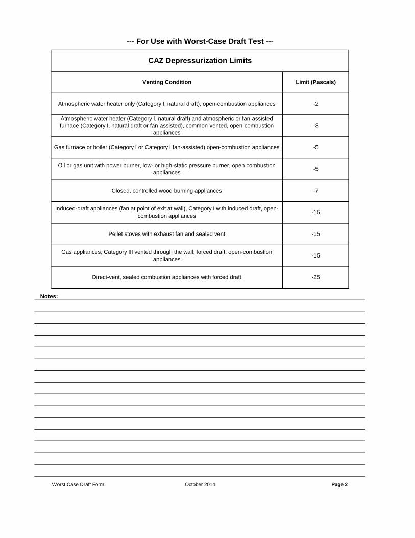
Direct-vent, sealed combustion appliances with forced draft -25
Worst Case Draft Form October 2014 Page 2
Notes:
Induced-draft appliances (fan at point of exit at wall), Category I with induced draft, open-combustion appliances
-15
Pellet stoves with exhaust fan and sealed vent -15
Gas appliances, Category III vented through the wall, forced draft, open-combustion appliances
-15
Gas furnace or boiler (Category I or Category I fan-assisted) open-combustion appliances -5
Oil or gas unit with power burner, low- or high-static pressure burner, open combustion appliances
-5
Closed, controlled wood burning appliances -7
Venting Condition Limit (Pascals)
Atmospheric water heater only (Category I, natural draft), open-combustion appliances -2
Atmospheric water heater (Category I, natural draft) and atmospheric or fan-assisted furnace (Category I, natural draft or fan-assisted), common-vented, open-combustion
appliances-3
CAZ Depressurization Limits
--- For Use with Worst-Case Draft Test ---

Initial Audit Date:
Final Insp. Date:
sq ft
cu ft
pa
pa
pa
pa
pa
pa pa
# #
1 pa pa 10 pa pa
2 pa pa 11 pa pa
3 pa pa 12 pa pa
4 pa pa 13 pa pa
5 pa pa 14 pa pa
6 pa pa 15 pa pa
7 pa pa 16 pa pa
8 pa pa 17 pa pa
9 pa pa 18 pa pa
pa pa pa
pa pa pa
pa pa pa
pa pa pa
pa pa pa
pa pa pa
pa pa pa
pa pa pa
# #
1 pa pa 5 pa pa
2 pa pa 6 pa pa
3 pa pa 7 pa pa
4 pa pa 8 pa pa
October 2014
Location
Final Building Pressure:Initial Building Pressure:
CFM50Fan PressureRing (Open, A, B or C)
CFM @ 50
CFM @ 50
Notes:
Attachment 2.4
Missouri Weatherization Assistance ProgramDiagnostic Field Form
Name: Job #:
Friable Asbestos Present:
If Present, Test Results:
If Present, Test Results:
Final Inspection
Blower Door
CFM @ 50Initial Audit
Test Period
In Progress 1
In Progress 2
In Progress 3
CFM @ 50
CFM @ 50
Duct Pressure Pan Testing
Initial FinalLocation Location Initial Final
Zonal Pressure Diagnostics (WRT Indoors)
Attic 1
Attic 2
Unconditioned Basement/Crawl 1
Location Building Pressure Initial Final
Other:
Attic 3
Unconditioned Basement/Crawl 2
Attached Garage
Other:
House Data
Number of Stories:
Number of Occupants:
Square Footage of Conditioned Space:
Volume of Conditioned Space:
Air Handler Dominant Duct Leakage
*Negative- supply duct leakage to outside, Positive- return leakage to outside, Unchanged- equal supply and return leakage to outside.
Air Handler Pressure Balance
With all exterior doors/windows closed and all interior doors open, the pressure in the home:
Room Initial Final Room Initial Final
Vermiculite Present: Yes No
Becomes more Negative Becomes more Positive Is Unchanged
Yes No
Positive Negative Untested
Positive Negative Untested

Date:
kBtu kBtu
°F to °F
Adequate Combustion Air
Manufacturer: Serial No:
Model No.:
Cooling Output: kBtu Heat Pump Heating Output: kBtu
Type:
Model No.: Gallons: Tank Leak:
Fuel Type:
kBtu kBtu
% °F to °F
-over- October 2014
AFUE: Designed Heat Rise Range:
Manufacturer: Serial No:
Model No.: Input: Output:
Venting:
Comments
FINAL INSPECTION- Replacement Heating System Information -FINAL INSPECTION
* Note: SEER values are not given on Room Air Conditioners, EER values are given and must be converted to SEER.
General Water Heater Information
Manufacturer: Serial No:
General Air Conditioning and Heat Pump Information
SEER*: HSPF(for heat pumps):
High Limit Setting Air Conditioning Coil
Fan On/Off Control A-Coil Condition
Heating System Controlls and Components
Thermostat Location Blower Drive
Anticipator Blower Wheel
Carbon Indicators: Safety Disconnects Present
Ductwork Holes:
Gas Leaks Designed Heat Rise Range:
Venting Problems: Asbestos Present:
Existing System Type:
Is Heating System Working? Cracked Heat Exchanger
High Carbon Monoxide Clean and Tune Needed
Primary Fuel Type:
Secondary Fuel Type:
Manufacturer: Serial No:
Model No.: Input: Output:
Attachment 2.5
Missouri Weatherization Assistance ProgramMechanical Systems Audit Form
Name: Job #:
General Heating System Information
Natural Gas Propane Oil Electric Wood Other
Natural Gas Propane Oil Electric Wood Other
OK Relocate
Needs Adjustment
Needs Adjustment
Needs Adjustment
Belt Direct Drive
Clean Dirty
Yes No
Clean Dirty
Atmospherically Drafting Fan Assisted Draft Condensing Unit Other:
Central Air Conditioner Room Air Conditioner Air Source Heat Pump Geothermal Heat Pump
Yes No
Yes No
Natural Gas Propane Electric Heat Pump Other:
No AC
Orphaned (No Liner) Commonly Vented Power Vented N/A (Electric)Orphaned (with Liner)
Yes
Yes
Yes
Yes
Yes
No
No
No
No
No
Yes
Yes
Yes
Yes
Yes
No
No
No
No
No
OK
OK
OK

°F °F °F
October 2014Attach the Combustion Gas Analyzer Printouts to This Page
- - Pre-Test- - - - Pre-Test- -
Water Heater
Port 1 Port 2 Gas Oven Other
Port 1 Port 2 Port 3 Port 4
- - Pre-Test- - - - Pre-Test- - Furnace - - Pre-Test- - - - Pre-Test- -
DIAGNOSTIC TESTS: Pre-Test
Return Air Temp: Supply Air Temp: Heat Rise (∆T):

°F °F °F
October 2014Attach the Combustion Gas Analyzer Printouts to This Page
- - Post-Test- - - - Post-Test- -
Water Heater
Port 1 Port 2 Gas Oven Other
Port 1 Port 2 Port 3 Port 4
- - Post-Test- - - - Post-Test- - Furnace - - Post-Test- - - - Post-Test- -
DIAGNOSTIC TESTS: Post-Test
Return Air Temp: Supply Air Temp: Heat Rise (∆T):

Date:
kWh
Operable Window: Operable Window:
Kitchen Exhaust Fan: Bath Exhaust Fan:
Measured Exhaust Fan Flow Rate: CFM Measured Exhaust Fan Flow Rate: CFM
Kitchen Volume:
Operable Window: Operable Window:
Bath Exhaust Fan: Bath Exhaust Fan:
Measured Exhaust Fan Flow Rate: CFM Measured Exhaust Fan Flow Rate: CFM
October 2014
Attachment 2.6
Comments
cu. ft.
Bath 2 Bath 3
Mechanical Ventilation Information
Kitchen Bath 1
Number of Bulbs: Size (watts): Use (hrs/day):
Number of Bulbs: Size (watts): Use (hrs/day):
Number of Bulbs: Size (watts): Use (hrs/day):
Number of Bulbs: Size (watts): Use (hrs/day):
Avg. Shower Use (per shower): min/day Note that Low Flow Shower Heads average less than 2.5 GPM
Existing Incandescent Lighting
Number of Bulbs: Size (watts): Use (hrs/day):
Energy usage: Installation Cost:
Existing Shower Heads
Number of Shower Heads: Average Gallons Per Minute (GPM):
New Refrigerator Model
Manufacturer: Serial No:
Model No.: Cubic Feet:
Model No.: Cubic Feet:
Refrigerator Metered: Information on NEAT/MHEA Database:
Metered Consumption Metering Minutes: Meter Reading (kWh):
Style:
Defrost:
Available Space Dimensions Height (in): Width (in): Depth (in):
Missouri Weatherization Assistance ProgramBaseload Replacement and Ventilation Audit Form
Name:
Existing Refrigerator Model
Manufacturer: Serial No:
Job #:
NoYes
Top Freezer Bottom Freezer Side by Side Single Door Single Door w/ Freezer Other
Manual Other
NoYes
Automatic Partial Automatic
Continious Intermitent N/A
Yes No
Continious Intermitent N/A
Yes No
Continious Intermitent N/A
Yes No
Continious Intermitent N/A
Yes No

Date:
●
●
●
●
Notes:
October 2014
Attachment 2.7
Associated ECM(s):
Justification for Tying to ECM(s):
Incidental Repair #6 Incidental Measure:
Associated ECM(s):
Justification for Tying to ECM(s):
Incidental Repair #5 Incidental Measure:
Associated ECM(s):
Justification for Tying to ECM(s):
Incidental Repair #4 Incidental Measure:
Associated ECM(s):
Justification for Tying to ECM(s):
Incidental Repair #3 Incidental Measure:
Associated ECM(s):
Justification for Tying to ECM(s):
Incidental Repair #2 Incidental Measure:
Incidental Repair Justification and Low-Cost/No-Cost ActivitiesIncidental repairs, as defined by 10 CFR 440, means those repairs necessary for the effective performance or preservation of weatherization materials.Incidental repairs must be limited to those minor repairs installed by the Subgrantee and can only be installed in association with energy conservation measures (ECM) installed by the Subgrantee.On the form below for each incidental repair, fill out the incidental repair measure name, the associated ECM(s) for the incidental repair and the justification for installing the incidental repair (how it is necessary for the ECM(s)).For Low-Cost/No-Cost Activities enter material name in Incidental Measure box, enter 'LCNC' in Asociated ECM(s) box and just the Justification box to explain how material is cost effective.
Incidental Repair #1 Incidental Measure:
Associated ECM(s):
Justification for Tying to ECM(s):
Missouri Weatherization Assistance ProgramIncidental Repair Justification Form
Name: Job #:
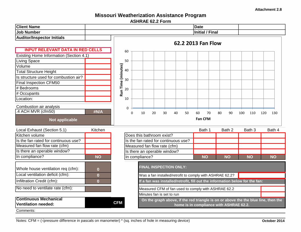
Client NameJob NumberAuditor/Inspector Initials
Existing Home Information (Section 4.1)Living SpaceVolumeTotal Structure HeightIs structure used for combustion air?Final Inspection CFM50# Bedrooms# OccupantsLocation:
Combustion air analysis.4 ACH MVR (cfm50) #N/A
Local Exhaust (Section 5.1) Kitchen Bath 1 Bath 2 Bath 3 Bath 4Kitchen volumeIs the fan rated for continuous use?Measured fan flow rate (cfm)Is there an operable window?In compliance? NO NO NO NO NO
Whole house ventilation req (cfm): 0Local ventilation deficit (cfm): 0Infiltration Credit (cfm): 0
No need to ventilate rate (cfm):
Continuous Mechanical Ventilation needed: CFM
Comments:
October 2014
In compliance?
Not applicable
Initial / FinalDate
INPUT RELEVANT DATA IN RED CELLS
Attachment 2.8
Notes: CFM = (√pressure difference in pascals on manometer) * (sq. inches of hole in measuring device)
Missouri Weatherization Assistance ProgramASHRAE 62.2 Form
FINAL INSPECTION ONLY:
Measured CFM of fan used to comply with ASHRAE 62.2
Minutes fan is set to run
Was a fan installed/retrofit to comply with ASHRAE 62.2?
If a fan was installed/retrofit, fill out the information below for the fan:
On the graph above, if the red triangle is on or above the the blue line, then the home is in compliance with ASHRAE 62.2.
Does this bathroom exist?Is the fan rated for continuous use?Measured fan flow rate (cfm)Is there an operable window?
0
10
20
30
40
50
60
0 10 20 30 40 50 60 70 80 90 100 110 120 130
Ru
n T
ime
(m
inu
tes)
Fan CFM
62.2 2013 Fan Flow
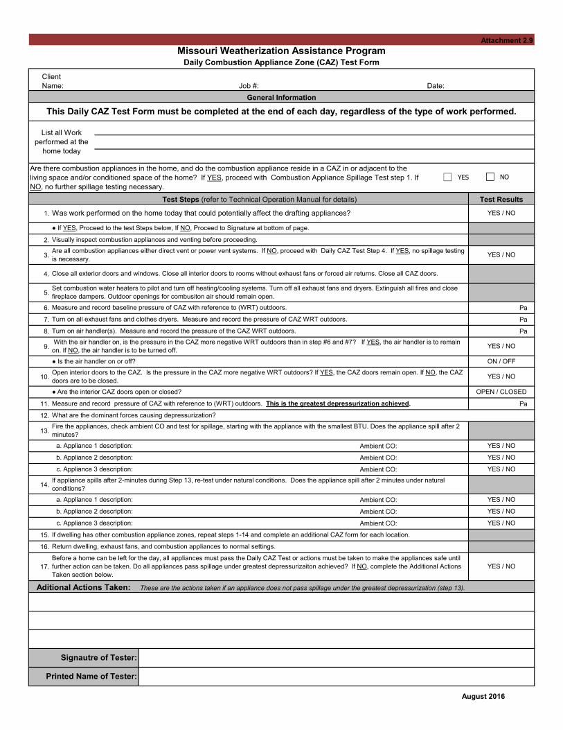
1.
2.
3.
4.
5.
6. Pa
7. Pa
8. Pa
9.
10.
11. Pa
12.
13.
Ambient CO:
Ambient CO:
Ambient CO:
14.
Ambient CO:
Ambient CO:
Ambient CO:
15.
16.
17.
August 2016
List all Work
performed at the
home today
● If YES, Proceed to the test Steps below, If NO, Proceed to Signature at bottom of page.
Are there combustion appliances in the home, and do the combustion appliance reside in a CAZ in or adjacent to the
living space and/or conditioned space of the home? If YES, proceed with Combustion Appliance Spillage Test step 1. If
NO, no further spillage testing necessary.
● Is the air handler on or off? ON / OFF
Open interior doors to the CAZ. Is the pressure in the CAZ more negative WRT outdoors? If YES, the CAZ doors remain open. If NO, the CAZ
doors are to be closed.YES / NO
Measure and record baseline pressure of CAZ with reference to (WRT) outdoors.
Turn on all exhaust fans and clothes dryers. Measure and record the pressure of CAZ WRT outdoors.
Printed Name of Tester:
This Daily CAZ Test Form must be completed at the end of each day, regardless of the type of work performed.
Turn on air handler(s). Measure and record the pressure of the CAZ WRT outdoors.
Aditional Actions Taken: These are the actions taken if an appliance does not pass spillage under the greatest depressurization (step 13).
Signautre of Tester:
If dwelling has other combustion appliance zones, repeat steps 1-14 and complete an additional CAZ form for each location.
Return dwelling, exhaust fans, and combustion appliances to normal settings.
Before a home can be left for the day, all appliances must pass the Daily CAZ Test or actions must be taken to make the appliances safe until
further action can be taken. Do all appliances pass spillage under greatest depressurizaiton achieved? If NO, complete the Additional Actions
Taken section below.
YES / NO
b. Appliance 2 description: YES / NO
c. Appliance 3 description: YES / NO
If appliance spills after 2-minutes during Step 13, re-test under natural conditions. Does the appliance spill after 2 minutes under natural
conditions?
a. Appliance 1 description: YES / NO
b. Appliance 2 description: YES / NO
c. Appliance 3 description: YES / NO
Fire the appliances, check ambient CO and test for spillage, starting with the appliance with the smallest BTU. Does the appliance spill after 2
minutes?
a. Appliance 1 description: YES / NO
● Are the interior CAZ doors open or closed? OPEN / CLOSED
Measure and record pressure of CAZ with reference to (WRT) outdoors. This is the greatest depressurization achieved.
What are the dominant forces causing depressurization?
With the air handler on, is the pressure in the CAZ more negative WRT outdoors than in step #6 and #7? If YES, the air handler is to remain
on. If NO, the air handler is to be turned off.YES / NO
Are all combustion appliances either direct vent or power vent systems. If NO, proceed with Daily CAZ Test Step 4. If YES, no spillage testing
is necessary.YES / NO
Close all exterior doors and windows. Close all interior doors to rooms without exhaust fans or forced air returns. Close all CAZ doors.
Set combustion water heaters to pilot and turn off heating/cooling systems. Turn off all exhaust fans and dryers. Extinguish all fires and close
fireplace dampers. Outdoor openings for combusiton air should remain open.
Test Steps (refer to Technical Operation Manual for details) Test Results
Was work performed on the home today that could potentially affect the drafting appliances? YES / NO
Visually inspect combustion appliances and venting before proceeding.
General Information
Attachment 2.9
Missouri Weatherization Assistance ProgramDaily Combustion Appliance Zone (CAZ) Test Form
Client
Name: Job #: Date:
YES NO

1
Attachment 3.1
Depressurization Blower Door Test Procedures
Below is a step by step guide on the proper procedure when performing a depressurization blower door test. This step by step guidance is based upon using the DG 700 and the Minneapolis Blower Door.
1. Perform a visual inspection of the attic and home. Inspect for vermiculite insulation inthe attic. If vermiculite is present, do not perform a blower door test unless thevermiculate has been tested and the results were negative for asbestos. Do not conduct ablower door test while a wood stove, fireplace or vented space heater is operating.
2. Turn water heater to pilot.• Record water heater temperature setting from the thermostat control knob.
______ ºF3. Turn the furnace and/or air conditioner off.
• Record temperature setting from thermostat. ______ ºF4. Set house up in winter conditions. Close all windows and exterior doors. Open all
interior doors, including closet doors.5. Setup the blower door in an appropriate exterior door.
• The blower door should not be setup in a door located within an enclosed porch.
• Run a hose outside the door at with the end terminating at least five feet from theblower door and not directly in the path of exhaust of the blower door. The otherend of the hose needs to be run through the door cover as it will be connected tothe DG 700.
• Examine the blower door fan to ensure that the fan flow direction is setup for adepressurization blower door test.
6. Connect the hose ran to outside (as described in step 5) to the Channel A reference portof the DG700.
7. Connect another hose to the Channel B input port and to the single pressure tap (metalnipple) on the blower door fan.
8. At this time make sure that all of the flow rings are installed in the blower door fan.9. Turn on the DG 700 then in the following order:
• Press the ‘Mode’ twice until the mode reads PR/FL@50.• Press the ‘Base Line’ button.
• Press the ‘Start’ button and wait 20 seconds (if windy wait 60 to 120 seconds).
• Press the ‘Enter’ button.10. On the blower door fan, take off appropriate flow ring. If not sure what flow ring(s) to
take off, then take off all of the flow rings to have the fan in the Open configuration.11. On the DG 700 press the ‘Config’ button until the appropriate flow ring is selected.

2
12. On the gauge mounting board, turn the fan controller switch to turn on the fan. Continue to slowly adjust the fan speed until the DG 700 reaches between -45 and -55 pascals.
13. If the DG 700 continually flashes “LO”, then a fan flow ring needs to be installed in the blower door fan. If it is not flashing “LO”, move onto step 14.
• Install a fan flow ring, if the blower door fan was in the open configuration install the A ring. If the blower door fan was in the A ring configuration, install the B ring and so on.
• Make sure that if a fan flow ring is installed that the appropriate flow ring is selected on the DG 700 (see step 11).
14. With this configuration the blower door is taking a single point test at -50 pascals, as the DG 700 is converting all figures and showing what the results of the blower door at -50 pascals.
15. Record CFM50 as shown on the DG 700. This is the blower door test results for the home. ______ CFM50
16. Turn the fan down from between -45 and -55 pascals to approximately -30 pascals. Leave the blower door running and check for air leaks throughout the home (duck work, attic hatches, plumbing bypasses, windows, around doors, door latches, etc.).
17. Look for biggest leak by room. Use the DG 700 with a hose to the Channel A input port and place the hose into a room. If the DG 700 reads more than 5 pa, then there is a connection between the room and to outside the pressure boundary of the home. Use this information to determine where air sealing should be prioritized.
18. Re-set furnace temperature and pilot lights to original state (see steps 1 and 2). DG-700 Pressure and Flow Gauge

1
Attachment 3.2
Mechanical Systems Audit Procedures
Below is step by step guide on the proper procedure when performing a worst case draft test and a combustion test on a combustion appliance zone (CAZ) that contains atmospherically drafting and/or fan assisted draft combustion appliances. This step by step is based upon using the DG 700 Pressure and Flow Gauge and all appliances being located within a single CAZ and commonly vented. If appliances located in multiple CAZ, then this procedure will have to be performed in its entirety for each CAZ.
1. Turn on personal CO monitor (Rattler) outside, leave on through testo Record outside ambient CO ______ ppm
2. Record outdoor temperature ______ ºF3. Turn gas sniffer on outside4. Check gas line for leaks outside and then inside
o If any gas leaks found, test with a mixture of soap and water to verify gas leak.Mark any found gas leaks for repair.
o Check for pre-1973 flex gas line5. Set house up in winter conditions. Close all windows and exterior doors. Open all
interior doors, including closet doors.6. Check the furnace filter. If the filter is dirty replace the filter or if no replacement filter is
available, remove the filter for the purpose of the worst case draft test.7. Turn water heater to pilot.
o Record water heater temperature setting from the thermostat control knob.______ ºF
8. Turn the furnace and/or air conditioner off.o Record temperature setting from thermostat. ______ ºF
9. Record baseline number with regards to (WRT) outdoors on the DG 700. ______ pao Connect hose to Channel A reference port and run hose to outside of the building
shell. (This is how the manometer will need to be set up for all measurementsthat are WRT outdoors.)
10. Turn on all exhaust fans, kitchen range hood(s) (if venting outside), clean the dryer linttrap, remove clothes from dryer and turn on the dryer.
11. Check each interior door to see if they should be open or closed. Start with the furthestdoor from the CAZ.
o Use DG 700 (use a different DG 700 than what is connected measuring baselineor disconnect DG 700 from tube measuring baseline then reconnect whenmeasuring WRT outdoors), connect hose to Channel A input port with tube inroom and you outside the room. Close the door, if the pressure reading onChannel A is positive then leave the door close, if the pressure reading is negative

2
or zero then leave the door open. Make sure to check door to CAZ (note that you will be in CAZ and tube will be in hallway for the door to the CAZ).
12. Record the depressurization with the exhaust fans running WRT outdoors. ______ pa 13. Turn on the air handler for the furnace and/or air conditioner, record number WRT
outdoors. ______ pa 14. Re-check all doors if the air handler impact causes the depressurization to be more
negative than the reading before the air handler was turned on. Record number WRT outdoors if doors re-checked. ______ pa
15. Calculate net difference between Worst Case and baseline. This is the Worst Case Depressurization. ______ pa
o Most negative value of step 12, 13 or 14 and step 9. o Example: if step 14 was most negative with a reading of -4 pa and step 9 was -1
pa, the worst case depressurization is -3 pa. 16. Check CAZ depressurization limit of combustion equipment. Does the combustion
equipment pass the CAZ depressurization limit? YES or NO o Refer to Table III-1
17. Go outside and turn on the combustion gas analyzer (Bacharach) 18. Start the smallest BTU appliance (typically the water heater and henceforth referred to as
the water heater) 19. Check spillage all around the draft diverter. Spillage must stop within 60 seconds. Does
spillage stop within 60 seconds? YES or NO 20. If spillage fails, put the home into natural conditions and test spillage again. 21. Check personal CO monitor (Rattler) for ambient CO. Record ambient CO. ______ ppm 22. Check draft in vent connector 1 to 2 feet from diverter or first elbow. This is the draft
for the water heater. ______ pa o On DG 700 connect hose to Channel A input port, with no hose on the reference
port. 23. Check water heater baffle CO on both sides after steady state (or after 10 minutes) down
throat of water heater. Record CO in baffle 1 ______ ppm; CO in baffle 2 ______ ppm. 24. With water heater still on, start furnace and check spillage on furnace and also again on
the water heater. Does all spillage stop within 60 seconds? YES or NO 25. Check personal CO monitor (Rattler) for ambient CO. Record ambient CO. ______ ppm 26. Check furnace CO after steady state (or after 10 minutes) in appropriate location.
o Record CO in all ports if atmospherically drafting furnace (port 1______ ppm, port 2 _____ ppm, port 3 ______ ppm, port 4 ______ ppm) or record CO in vent connector if fan assisted draft furnace. ______ ppm
27. Check draft in the furnace vent connector 1to 2 feet from diverter or first elbow. This is the draft for the furnace. ______ pa
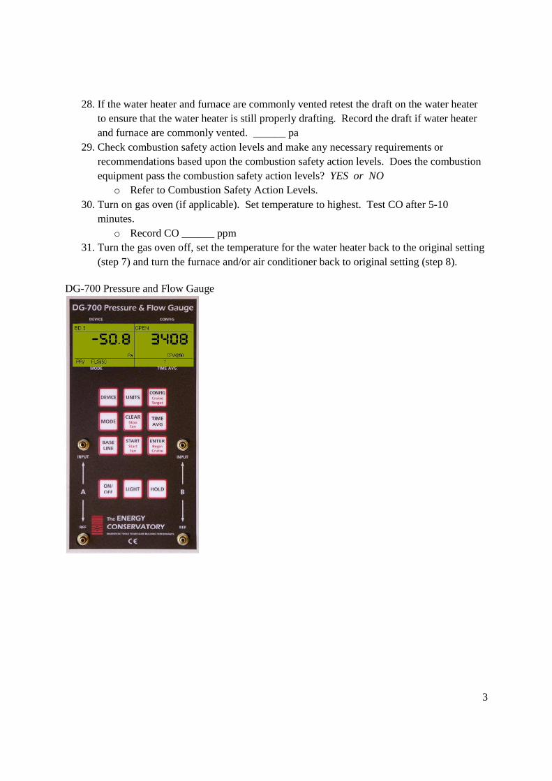
3
28. If the water heater and furnace are commonly vented retest the draft on the water heater to ensure that the water heater is still properly drafting. Record the draft if water heater and furnace are commonly vented. ______ pa
29. Check combustion safety action levels and make any necessary requirements or recommendations based upon the combustion safety action levels. Does the combustion equipment pass the combustion safety action levels? YES or NO
o Refer to Combustion Safety Action Levels. 30. Turn on gas oven (if applicable). Set temperature to highest. Test CO after 5-10
minutes. o Record CO ______ ppm
31. Turn the gas oven off, set the temperature for the water heater back to the original setting (step 7) and turn the furnace and/or air conditioner back to original setting (step 8).
DG-700 Pressure and Flow Gauge
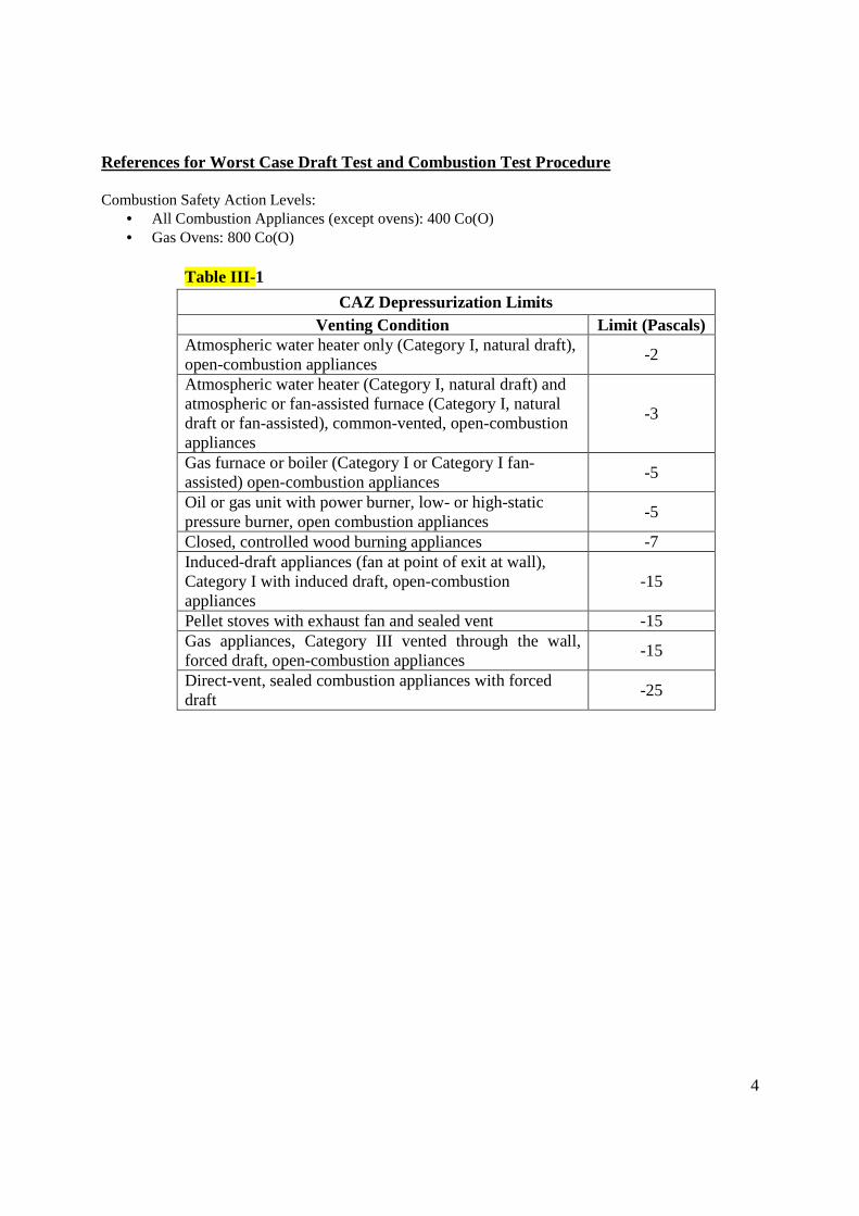
4
References for Worst Case Draft Test and Combustion Test Procedure Combustion Safety Action Levels:
• All Combustion Appliances (except ovens): 400 Co(O) • Gas Ovens: 800 Co(O)
Table III-1
CAZ Depressurization Limits Venting Condition Limit (Pascals)
Atmospheric water heater only (Category I, natural draft), open-combustion appliances
-2
Atmospheric water heater (Category I, natural draft) and atmospheric or fan-assisted furnace (Category I, natural draft or fan-assisted), common-vented, open-combustion appliances
-3
Gas furnace or boiler (Category I or Category I fan-assisted) open-combustion appliances
-5
Oil or gas unit with power burner, low- or high-static pressure burner, open combustion appliances
-5
Closed, controlled wood burning appliances -7 Induced-draft appliances (fan at point of exit at wall), Category I with induced draft, open-combustion appliances
-15
Pellet stoves with exhaust fan and sealed vent -15 Gas appliances, Category III vented through the wall, forced draft, open-combustion appliances
-15
Direct-vent, sealed combustion appliances with forced draft
-25

1
Attachment 3.3
Final Inspection Procedure
Below is step by step guide on the proper procedure when performing a final inspection. In addition, the Worst Case Draft Test and Combustion Test Procedure and Depressurization Blower Door Test Procedure will be necessary for this procedure, as both will be referenced in the Final Inspection Procedure.
1. Talk to the cliento Discuss what will be done during the final inspection.o Have the client describe any issues that the client feels remain unresolved.
2. Review the work order and the NEAT/MHEA Recommended Measures.o Check to see if all measures on the NEAT/MHEA Recommended Measures are
on the work order� If a measure is not on the work order, but is on the NEAT/MHEA
Recommended Measures, examine the client file for a change order or aclient refusal. If no change order or client refusal is present, then theagency needs to complete the measure on the NEAT/MHEARecommended Measures that is not on the work order.
3. Go through the work order and inspect each measure that was called for to be installedand/or performed at the home. Measures must be up to agency and state standards,installed in such a way that the measure will remain intact and effective and incompliance with all Federal, State and Local regulations.
o If a measure is not installed in such a manner as described above, then additionalwork needs to be performed to bring the installed measure within compliance.
o Ensure that all incidental repairs are properly justified on the Incidental RepairJustification Form (Attachment 2.7) and any health and safety measuresreplacements are properly justified in the client file.
4. A blower door test needs to be performed on all homes, except those with health andsafety issues preclude the performance of a blower door test.
o If a blower door test cannot be performed, it must be documented why a blowerdoor test was unable to be performed. An operating wood stove, fireplace orvented space heater is not adequate reason to not perform a blower door test. Inthese circumstances, the final inspector needs to come back at a later time andperform the blower door test when the wood stove, fireplace or vented spaceheater is not operational.
o See the Depressurization Blower Door Test Procedure for the proper procedure onperforming a depressurization blower door test.
5. All exhaust fans in the home must be tested and the actual CFM(s) from the exhaust fansmust be entered into the DED/DE ASHRAE 62.2 Form, along with the actual blower

2
door reading from the final inspection and any additional necessary information to acquire the necessary continuous mechanical ventilation for the home.
o If mechanical ventilation has been retrofit or installed to meet the ASHRAE 62.2 standard, the installed mechanical ventilation must be set to the correct flow rate to meet the continuous mechanical ventilation standard given on the ASHRAE 62.2 Form.
o If mechanical ventilation is necessary and mechanical ventilation has not been installed, then mechanical ventilation needs to be installed in the home to comply with the ASHRAE 62.2 standards and proper adjustments must be made to comply with the required ventilation.
6. If the home has a gas water heater or heating system, a mechanical systems audit must be performed.
o See the Worst Case Draft Test and Combustion Test Procedure for the proper procedure on performing a mechanical systems audit.
o On all homes that have a mechanical systems audit performed, the Worst Case Draft Test Form and Mechanical Systems Audit Form must be completed during the final inspection.
7. Inspect the home for any existing health and safety issues that are a result of weatherization work. Any health and safety issues that are a result of weatherization work must be mitigated.
8. If all work at the home has been properly installed as described in Number 3, has a sufficient blower door reduction from Number 4 and complies with ASHRAE 62.2 and passes the necessary mechanical systems audit in Number 6, then the home may be considered completed.
o A completed home must have all of the necessary forms filled out in their entirety.
o The home must not have any lingering health and safety issues that are a result of weatherization.
o The home must meet the requirements given above in Numbers 3, 4, 5 and 6.

Attachment 3.4
Causes Causes
• Stack effect • Stack effect
• Exhaust appliances • Exhaust appliances in CAZ
Repairs • Exhaust appliances affecting the CAZ
• Eliminate / Reduce CFM of exhaust Repairs
• Isolate combustion appliances • Eliminate / Reduce CFM of exhaust
• Replace the combustion appliances • Isolate combustion appliances
• Provide make-up air • Sealed combustion furnes, electric or
power vented water heaters
• Provide make-up air
• Seal the room to isolate CAZ from
exhaust fans affecting the CAZ
• Stack effect • Stack effect
• Supply duct leakage to the outside • Return duct leakage in CAZ
• Interior door closure
• Seal return ducts in CAZ
• Seal supply ducts outside the thermal boundary
• Pressure relieve interior rooms
Causes
• Return duct leakage to the outside
Causes Repairs
• Return duct leakage to the outside • Seal supply ducts in the CAZ
• Interior door closure
Repairs
• Seal return ducts outside the thermal boundary• Pressure relieve interior rooms
Important Note: There may be more than one 'Worst Case Depressurization' scenario which will not allow an appliance to function. Retest the Worst Case Depressurization after every repair is made.
Combusiton Appliance Zone Testing - What do the numbers mean? Probable causes associated with different scenarios.
CAZ Pressure Diagnostics
CAZ DoorClosed
Negative Number
Causes
Negative Number
Negative Number
Open
Air H
andler
On
Off
Negative NumberCauses
Repairs
Positive Number
Repairs
Positive Number

H/Z 44 42 40 38 36 34 32 30 28 26 24 22 20 18 16 14 12 10 8 6 4 2 0
Z/O 6 8 10 12 14 16 18 20 22 24 26 28 30 32 34 36 38 40 42 44 46 48 50 Before Hole50 0 0.00 0.00 0.00 0.00 0.00 0.00 0.00 0.00 0.00 0.00 0.00 0.00 0.00 0.00 0.00 0.00 0.00 0.00 0.00 0.00 0.00 0.00 0.00 10%49 1 0.35 0.29 0.25 0.22 0.20 0.18 0.17 0.15 0.15 0.14 0.13 0.12 0.12 0.11 0.11 0.10 0.10 0.10 0.09 0.09 0.09 0.09 15%48 2 0.68 0.54 0.45 0.39 0.35 0.32 0.29 0.27 0.25 0.23 0.22 0.21 0.20 0.19 0.18 0.17 0.17 0.16 0.15 0.15 0.15 0.14 20%47 3 0.84 0.68 0.58 0.51 0.45 0.41 0.38 0.35 0.33 0.31 0.29 0.27 0.26 0.25 0.24 0.23 0.22 0.21 0.20 0.20 0.19 25%46 4 1.23 0.96 0.80 0.68 0.60 0.54 0.49 0.45 0.42 0.39 0.37 0.35 0.33 0.32 0.30 0.29 0.28 0.27 0.26 0.25 0.24 >26%45 5 1.30 1.05 0.89 0.77 0.68 0.62 0.56 0.52 0.48 0.45 0.43 0.40 0.38 0.37 0.35 0.33 0.32 0.31 0.30 0.29
44 6 1.76 1.36 1.12 0.96 0.84 0.75 0.68 0.63 0.58 0.54 0.51 0.48 0.45 0.43 0.41 0.39 0.38 0.36 0.35 0.34
43 7 1.76 1.41 1.18 1.02 0.90 0.81 0.74 0.68 0.63 0.59 0.56 0.53 0.50 0.48 0.45 0.43 0.42 0.40 0.39
42 8 2.28 1.76 1.44 1.23 1.08 0.96 0.87 0.80 0.73 0.68 0.64 0.60 0.57 0.54 0.52 0.49 0.47 0.45 0.44
41 9 2.20 1.76 1.47 1.27 1.12 1.01 0.92 0.84 0.78 0.73 0.68 0.65 0.61 0.58 0.55 0.53 0.51 0.49
40 10 2.80 2.15 1.76 1.49 1.30 1.16 1.05 0.96 0.89 0.82 0.77 0.72 0.68 0.65 0.62 0.59 0.56 0.54
39 11 2.65 2.11 1.76 1.51 1.33 1.20 1.09 1.00 0.92 0.86 0.81 0.76 0.72 0.68 0.65 0.62 0.60
38 12 3.32 2.54 2.07 1.76 1.53 1.36 1.23 1.12 1.03 0.96 0.90 0.84 0.80 0.75 0.72 0.68 0.65
37 13 3.09 2.45 2.04 1.76 1.55 1.38 1.26 1.15 1.07 0.99 0.93 0.87 0.83 0.79 0.75 0.71
36 14 3.83 2.93 2.38 2.02 1.76 1.56 1.41 1.28 1.18 1.09 1.02 0.96 0.90 0.86 0.81 0.78
35 15 3.54 2.80 2.33 2.00 1.76 1.57 1.42 1.30 1.21 1.12 1.05 0.99 0.93 0.89 0.84
34 16 4.35 3.32 2.70 2.28 1.98 1.76 1.58 1.44 1.33 1.23 1.15 1.08 1.01 0.96 0.91
33 17 3.98 3.14 2.61 2.24 1.97 1.76 1.59 1.46 1.34 1.25 1.17 1.10 1.04 0.98
32 18 4.86 3.70 3.01 2.54 2.20 1.95 1.76 1.60 1.47 1.36 1.27 1.19 1.12 1.06
31 19 4.42 3.49 2.89 2.48 2.18 1.94 1.76 1.61 1.48 1.38 1.29 1.21 1.14
30 20 5.38 4.09 3.32 2.80 2.43 2.15 1.93 1.76 1.61 1.49 1.39 1.30 1.23
29 21 4.86 3.83 3.18 2.72 2.38 2.13 1.92 1.76 1.62 1.50 1.41 1.32
28 22 5.89 4.48 3.63 3.06 2.65 2.34 2.11 1.91 1.76 1.63 1.51 1.42
27 23 5.30 4.18 3.46 2.96 2.59 2.31 2.09 1.91 1.76 1.63 1.52
26 24 6.41 4.86 3.94 3.32 2.87 2.54 2.28 2.07 1.90 1.76 1.64
25 25 5.75 4.52 3.74 3.20 2.80 2.49 2.25 2.06 1.89 1.76
24 26 6.92 5.25 4.25 3.57 3.09 2.73 2.45 2.23 2.04 1.89
23 27 6.19 4.86 4.02 3.44 3.01 2.68 2.42 2.20 2.03
22 28 7.43 5.64 4.55 3.83 3.32 2.93 2.63 2.38 2.18
21 29 6.63 5.21 4.30 3.67 3.21 2.86 2.58 2.35
20 30 7.95 6.02 4.86 4.09 3.54 3.12 2.80 2.54
19 31 7.07 5.55 4.58 3.91 3.42 3.04 2.74
18 32 8.46 6.41 5.17 4.35 3.76 3.32 2.97
17 33 7.51 5.89 4.86 4.15 3.63 3.23
16 34 8.98 6.79 5.48 4.61 3.98 3.51
15 35 7.95 6.24 5.14 4.39 3.83
14 36 9.49 7.18 5.79 4.86 4.20
13 37 8.39 6.58 5.42 4.63 (total path CFM50)12 38 10.00 7.56 6.10 5.12
11 39 8.83 6.92 5.71
10 40 10.52 7.95 6.41
9 41 9.27 7.26
8 42 11.03 8.33
7 43 9.71 ext exponent =0.65
6 44 11.54
Anthony Cox and Collin Olson, 2006
MaximumReduction
H/Z
Start Press
After Hole
CFM50
Flow Method: Hole Added from House to ZoneEnding Pressure After Making Hole to from House to Zone
CFM50
Unc
erta
inty
ba
sed
on 1
Pa
Err
ors
H/Z
May 25, 2006
ANSWER
Multiplier
CFM50 Diff
Attic Example (House in Winter Mode)Attic Access Closed with Hose Running to Blower Door Measure House CFM 50 (example: 2400 CFM50)Measure House to Attic Pressure (Verify with Attic to Outside)(example: 36 PA House to Attic)
Make Opening From House to Attic (enough for at least 6 PA Change)Measure House CFM 50 (example: 3000 CFM50)Measure House to Attic Pressure (Verify with Attic to Outside)(example: 20PA House to Attic)
Take 2nd Blower Door Reading (3000) - First Blower Reading (2400) = 600Look in Row with 36 H/Z and move over to Column with 20 H/Z to Find Multiplier =1.56
Take 600 X 1.56 = 936 (This is Maximum CFM50 REDUCTION AVAILABLE by sealing all holes to Attic)
To Determine Uncertainty Range multiply Answer by percentage in Uncertainty TableTo Determine Approximate Hole Size Divide Answer by 10 (936 / 10= 94 sq in)
Attachment 3.5

FOR OPENING THE DOOR FROM GARAGE TO OUTSIDE
All Doors to Garage Closed (House in winter mode)Get Blower Door to -50PA WRT Outside
closed pressure multiply CFM50 change by…H/G G/O int ext path A Measure House CFM 50 for Door Closed
2 48 1.14 0.14 0.14 B Measure Closed Door Zonal Pressure House WRT Garage3 47 1.19 0.20 0.19 (If Closed Door Zonal Pressure greater than 25PA you should use other side of this Sheet)4 46 1.24 0.25 0.245 45 1.29 0.31 0.29 Open Door from Garage to Outside6 44 1.34 0.37 0.34 Get Blower Door Back to -50PA WRT Outside 7 43 1.39 0.43 0.39 C Measure House CFM 50 for Door Open 8 42 1.44 0.49 0.44 Measure Zonal Pressure House WRT Garage (Should be 50)9 41 1.49 0.56 0.4910 40 1.54 0.63 0.54 D CFM 50 Difference = CFM 50 Door Open - CFM 50 Door Closed11 39 1.60 0.70 0.6012 38 1.65 0.78 0.65 Look up Closed Door Zonal Pressure for House WRT Garage on Table 13 37 1.71 0.87 0.7114 36 1.78 0.96 0.78 Enter Multipliers into labeled Multiplier Boxes Below15 35 1.84 1.06 0.84 Multiply CFM 50 Difference (D) x Multiplier in each row for results16 34 1.91 1.17 0.9117 33 1.98 1.29 0.98 Divide CFM 50 by 10 in each row To Determine Approx. Square inches of Leakage18 32 2.06 1.42 1.0619 31 2.14 1.56 1.14 B A C D20 30 2.23 1.71 1.23 Closed Door Pressure CFM 50 CFM 50 CFM 5021 29 2.32 1.88 1.32 House WRT Garage Door Closed Door Open Difference (C-A)22 28 2.42 2.07 1.4223 27 2.52 2.27 1.5224 26 2.64 2.50 1.6425 25 2.76 2.76 1.76 Leakage from Garage to House
below here you should probably use other side of card (D) CFM 50 Difference Multiplier CFM 50 Square Inches26 24 2.89 3.04 1.8927 23 3.03 3.36 2.0328 22 3.18 3.73 2.1829 21 3.35 4.14 2.35 Leakage from Garage to Outside30 20 3.54 4.61 2.54 (D) CFM 50 Difference Multiplier CFM 50 Square Inches31 19 3.74 5.15 2.7432 18 3.97 5.77 2.9733 17 4.23 6.50 3.2334 16 4.51 7.36 3.51 Total Path Leakage 35 15 4.83 8.38 3.83 (D) CFM 50 Difference Multiplier
Anthony Cox and Collin Olson, 2006
exponents=0.65 May 25, 2006
Gar
age
is le
akie
r to
the
hous
e th
an it
is to
the
outd
oors
.
OPEN A DOOR ( ZONE PRESSURE - SERIES LEAKAGE DIAGNOSTICS )
Maximum CFM 50 Reduction Available
x (path)
x (ext)
x (int)
Open Garage Door to Outside
Attachment 3.5
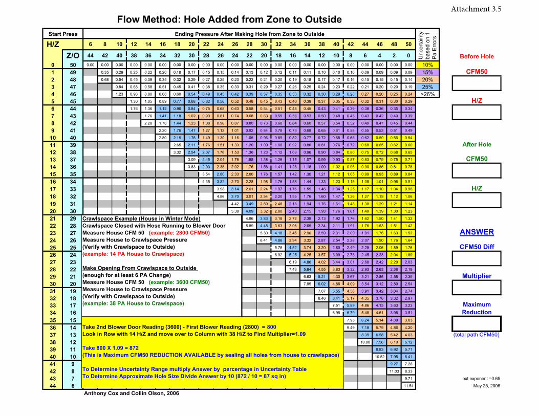
H/Z 6 8 10 12 14 16 18 20 22 24 26 28 30 32 34 36 38 40 42 44 46 48 50
Z/O 44 42 40 38 36 34 32 30 28 26 24 22 20 18 16 14 12 10 8 6 4 2 0 Before Hole0 50 0.00 0.00 0.00 0.00 0.00 0.00 0.00 0.00 0.00 0.00 0.00 0.00 0.00 0.00 0.00 0.00 0.00 0.00 0.00 0.00 0.00 0.00 0.00 10%1 49 0.35 0.29 0.25 0.22 0.20 0.18 0.17 0.15 0.15 0.14 0.13 0.12 0.12 0.11 0.11 0.10 0.10 0.10 0.09 0.09 0.09 0.09 15%2 48 0.68 0.54 0.45 0.39 0.35 0.32 0.29 0.27 0.25 0.23 0.22 0.21 0.20 0.19 0.18 0.17 0.17 0.16 0.15 0.15 0.15 0.14 20%3 47 0.84 0.68 0.58 0.51 0.45 0.41 0.38 0.35 0.33 0.31 0.29 0.27 0.26 0.25 0.24 0.23 0.22 0.21 0.20 0.20 0.19 25%4 46 1.23 0.96 0.80 0.68 0.60 0.54 0.49 0.45 0.42 0.39 0.37 0.35 0.33 0.32 0.30 0.29 0.28 0.27 0.26 0.25 0.24 >26%5 45 1.30 1.05 0.89 0.77 0.68 0.62 0.56 0.52 0.48 0.45 0.43 0.40 0.38 0.37 0.35 0.33 0.32 0.31 0.30 0.29
6 44 1.76 1.36 1.12 0.96 0.84 0.75 0.68 0.63 0.58 0.54 0.51 0.48 0.45 0.43 0.41 0.39 0.38 0.36 0.35 0.34
7 43 1.76 1.41 1.18 1.02 0.90 0.81 0.74 0.68 0.63 0.59 0.56 0.53 0.50 0.48 0.45 0.43 0.42 0.40 0.39
8 42 2.28 1.76 1.44 1.23 1.08 0.96 0.87 0.80 0.73 0.68 0.64 0.60 0.57 0.54 0.52 0.49 0.47 0.45 0.44
9 41 2.20 1.76 1.47 1.27 1.12 1.01 0.92 0.84 0.78 0.73 0.68 0.65 0.61 0.58 0.55 0.53 0.51 0.49
10 40 2.80 2.15 1.76 1.49 1.30 1.16 1.05 0.96 0.89 0.82 0.77 0.72 0.68 0.65 0.62 0.59 0.56 0.54
11 39 2.65 2.11 1.76 1.51 1.33 1.20 1.09 1.00 0.92 0.86 0.81 0.76 0.72 0.68 0.65 0.62 0.60
12 38 3.32 2.54 2.07 1.76 1.53 1.36 1.23 1.12 1.03 0.96 0.90 0.84 0.80 0.75 0.72 0.68 0.65
13 37 3.09 2.45 2.04 1.76 1.55 1.38 1.26 1.15 1.07 0.99 0.93 0.87 0.83 0.79 0.75 0.71
14 36 3.83 2.93 2.38 2.02 1.76 1.56 1.41 1.28 1.18 1.09 1.02 0.96 0.90 0.86 0.81 0.78
15 35 3.54 2.80 2.33 2.00 1.76 1.57 1.42 1.30 1.21 1.12 1.05 0.99 0.93 0.89 0.84
16 34 4.35 3.32 2.70 2.28 1.98 1.76 1.58 1.44 1.33 1.23 1.15 1.08 1.01 0.96 0.91
17 33 3.98 3.14 2.61 2.24 1.97 1.76 1.59 1.46 1.34 1.25 1.17 1.10 1.04 0.98
18 32 4.86 3.70 3.01 2.54 2.20 1.95 1.76 1.60 1.47 1.36 1.27 1.19 1.12 1.06
19 31 4.42 3.49 2.89 2.48 2.18 1.94 1.76 1.61 1.48 1.38 1.29 1.21 1.14
20 30 5.38 4.09 3.32 2.80 2.43 2.15 1.93 1.76 1.61 1.49 1.39 1.30 1.23
21 29 4.86 3.83 3.18 2.72 2.38 2.13 1.92 1.76 1.62 1.50 1.41 1.32
22 28 5.89 4.48 3.63 3.06 2.65 2.34 2.11 1.91 1.76 1.63 1.51 1.42
23 27 5.30 4.18 3.46 2.96 2.59 2.31 2.09 1.91 1.76 1.63 1.52
24 26 6.41 4.86 3.94 3.32 2.87 2.54 2.28 2.07 1.90 1.76 1.64
25 25 5.75 4.52 3.74 3.20 2.80 2.49 2.25 2.06 1.89 1.76
26 24 6.92 5.25 4.25 3.57 3.09 2.73 2.45 2.23 2.04 1.89
27 23 6.19 4.86 4.02 3.44 3.01 2.68 2.42 2.20 2.03
28 22 7.43 5.64 4.55 3.83 3.32 2.93 2.63 2.38 2.18
29 21 6.63 5.21 4.30 3.67 3.21 2.86 2.58 2.35
30 20 7.95 6.02 4.86 4.09 3.54 3.12 2.80 2.54
31 19 7.07 5.55 4.58 3.91 3.42 3.04 2.74
32 18 8.46 6.41 5.17 4.35 3.76 3.32 2.97
33 17 7.51 5.89 4.86 4.15 3.63 3.23
34 16 8.98 6.79 5.48 4.61 3.98 3.51
35 15 7.95 6.24 5.14 4.39 3.83
36 14 9.49 7.18 5.79 4.86 4.20
37 13 8.39 6.58 5.42 4.63 (total path CFM50)38 12 10.00 7.56 6.10 5.12
39 11 8.83 6.92 5.71
40 10 10.52 7.95 6.41
41 9 9.27 7.26
42 8 11.03 8.33
43 7 9.71 ext exponent =0.65
44 6 11.54
Anthony Cox and Collin Olson, 2006
H/Z
May 25, 2006
ANSWER
Multiplier
CFM50 Diff
MaximumReduction
H/Z
After Hole
CFM50
Start Press
Flow Method: Hole Added from Zone to OutsideEnding Pressure After Making Hole from Zone to Outside
CFM50
Unc
erta
inty
ba
sed
on 1
P
a E
rror
s
Crawlspace Example (House in Winter Mode)Crawlspace Closed with Hose Running to Blower Door Measure House CFM 50 (example: 2800 CFM50)Measure House to Crawlspace Pressure (Verify with Crawlspace to Outside)(example: 14 PA House to Crawlspace)
Make Opening From Crawlspace to Outside (enough for at least 6 PA Change)Measure House CFM 50 (example: 3600 CFM50)Measure House to Crawlspace Pressure (Verify with Crawlspace to Outside)(example: 38 PA House to Crawlspace)
Take 2nd Blower Door Reading (3600) - First Blower Reading (2800) = 800Look in Row with 14 H/Z and move over to Column with 38 H/Z to Find Multiplier=1.09
Take 800 X 1.09 = 872(This is Maximum CFM50 REDUCTION AVAILABLE by sealing all holes from house to crawlspace)
To Determine Uncertainty Range multiply Answer by percentage in Uncertainty TableTo Determine Approximate Hole Size Divide Answer by 10 (872 / 10 = 87 sq in)
Attachment 3.5
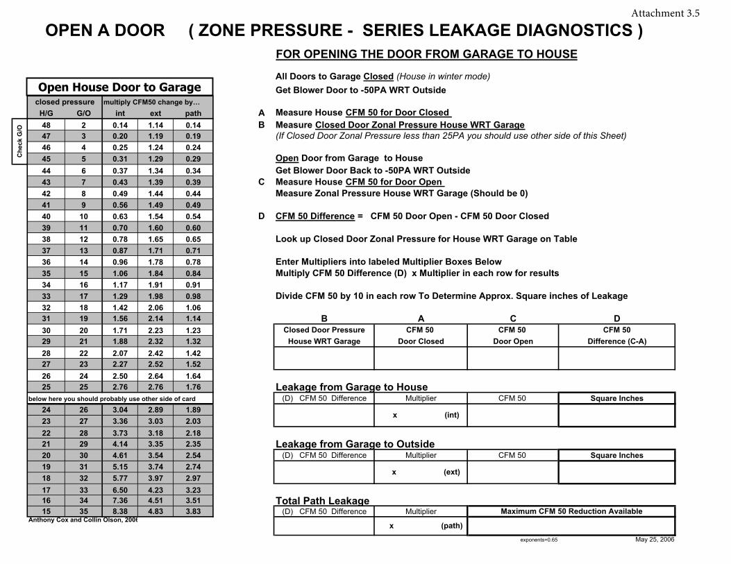
FOR OPENING THE DOOR FROM GARAGE TO HOUSE
All Doors to Garage Closed (House in winter mode)Get Blower Door to -50PA WRT Outside
closed pressure multiply CFM50 change by…H/G G/O int ext path A Measure House CFM 50 for Door Closed 48 2 0.14 1.14 0.14 B Measure Closed Door Zonal Pressure House WRT Garage47 3 0.20 1.19 0.19 (If Closed Door Zonal Pressure less than 25PA you should use other side of this Sheet)46 4 0.25 1.24 0.2445 5 0.31 1.29 0.29 Open Door from Garage to House44 6 0.37 1.34 0.34 Get Blower Door Back to -50PA WRT Outside 43 7 0.43 1.39 0.39 C Measure House CFM 50 for Door Open 42 8 0.49 1.44 0.44 Measure Zonal Pressure House WRT Garage (Should be 0)41 9 0.56 1.49 0.4940 10 0.63 1.54 0.54 D CFM 50 Difference = CFM 50 Door Open - CFM 50 Door Closed39 11 0.70 1.60 0.6038 12 0.78 1.65 0.65 Look up Closed Door Zonal Pressure for House WRT Garage on Table 37 13 0.87 1.71 0.7136 14 0.96 1.78 0.78 Enter Multipliers into labeled Multiplier Boxes Below35 15 1.06 1.84 0.84 Multiply CFM 50 Difference (D) x Multiplier in each row for results34 16 1.17 1.91 0.9133 17 1.29 1.98 0.98 Divide CFM 50 by 10 in each row To Determine Approx. Square inches of Leakage32 18 1.42 2.06 1.0631 19 1.56 2.14 1.14 B A C D30 20 1.71 2.23 1.23 Closed Door Pressure CFM 50 CFM 50 CFM 5029 21 1.88 2.32 1.32 House WRT Garage Door Closed Door Open Difference (C-A)28 22 2.07 2.42 1.4227 23 2.27 2.52 1.5226 24 2.50 2.64 1.6425 25 2.76 2.76 1.76 Leakage from Garage to House
below here you should probably use other side of card (D) CFM 50 Difference Multiplier CFM 50 Square Inches24 26 3.04 2.89 1.8923 27 3.36 3.03 2.0322 28 3.73 3.18 2.1821 29 4.14 3.35 2.35 Leakage from Garage to Outside20 30 4.61 3.54 2.54 (D) CFM 50 Difference Multiplier CFM 50 Square Inches19 31 5.15 3.74 2.7418 32 5.77 3.97 2.9717 33 6.50 4.23 3.2316 34 7.36 4.51 3.51 Total Path Leakage 15 35 8.38 4.83 3.83 (D) CFM 50 Difference Multiplier
Anthony Cox and Collin Olson, 2006
exponents=0.65 May 25, 2006
Che
ck G
/O
OPEN A DOOR ( ZONE PRESSURE - SERIES LEAKAGE DIAGNOSTICS )
Maximum CFM 50 Reduction Available
x (path)
x (ext)
x (int)
Open House Door to Garage
Attachment 3.5

Attachment 3.6
Ventilation for You and Your Home
As a part of the Weatherization Assistance Program, a mechanical ventilation fan was or is being retrofit or installed in your home. This sheet will help answer some of your questions regarding the ventilation fan.
Why do I need a ventilation fan? One of the most cost-effective measures in most home energy retrofits is air sealing. This gets rid of a lot of energy loss when it is cold outside. However, when the house is tighter indoor contaminants can build up more, especially when outdoor conditions are mild. The ventilation fan helps to make sure that contaminants are kept to acceptable levels. By doing good air sealing and then providing ventilation the weatherization program can optimize energy savings while ensuring that you and your family’s health is maintained.
How big does the fan have to be? The size of the fan is based on a national standard developed by the American Society of Heating Refrigeration and Air Conditioning Engineers (ASHRAE) – for more information visit www.ashrae.org. The amount of fan air flow depends on the number of people, the size of the home, the leakage of the home, and any ventilation you already have.
What contaminants are you talking about? Contaminants come from a number of sources, such as cooking, cleaning, storage of personal care products, cleaners, paints, bathing, and breathing. Some common contaminants which can cause indoor air quality problems and make people sick or cause damage are: Mold, Mildew, Formaldehyde, Carbon Monoxide, Volatile Organic Compounds (VOCs), Dirt and Dust Particles, Carbon Dioxide, Cooking Products, along with others.
What does this mean in regards to the Weatherization Program? As part of the overall energy saving upgrade for your home, a ventilation fan will be installed to remove contaminants and bring in fresh outside air.
Will the fan be loud? No, a requirement is that the fan be quiet - similar to a library whisper.
Wait, won't a fan increase my bills? The weatherization program requires very efficient fans. The amount of energy that the fan uses will cost a typical Missouri homeowner about $10 per year for the fan motor plus $20-40 per year for heating and cooling. The savings from the energy retrofit should pay for the cost of ventilation several times over per year.
What do I need to do? The fan is designed to run continuously for many years, but like all fans, it will require periodic maintenance. When the fan grille collects a noticeable amount of dust, it should be cleaned in order to run effectively and efficiently. To clean the fan, use a vacuum attachment or a damp rag. The grille can be removed or cleaned in place. Some fans may require additional maintenance, so refer to the product manual that was given to you when the fan was installed.
Can I say no to the fan? No, the fan is for your safety. If you do not want the fan installed in your home, we cannot proceed with the weatherization work. Weatherization of a house without proper ventilation increases the risk of reducing indoor air quality to an unsafe level.
What if I need to turn it off? Sometimes you will need to turn the fan off, such as for cleaning of the fan grille. There is an override switch which should only be used in case of emergency or when the fan needs to be turned off for cleaning or when work is being done on your home. If there is poor outdoor air quality (forest fire, chemical spill, etc.) you should temporarily turn the fan off, but remember to turn it back on later.
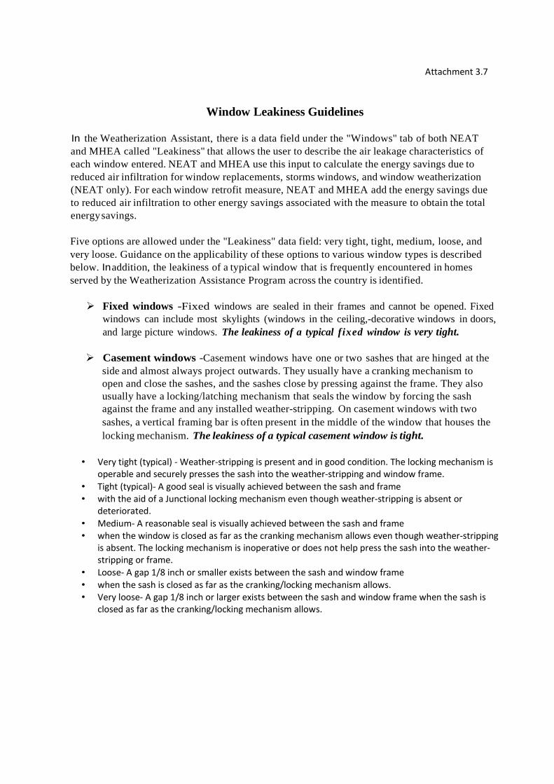
Attachment 3.7
Window Leakiness Guidelines
In the Weatherization Assistant, there is a data field under the "Windows" tab of both NEAT and MHEA called "Leakiness" that allows the user to describe the air leakage characteristics of each window entered. NEAT and MHEA use this input to calculate the energy savings due to reduced air infiltration for window replacements, storms windows, and window weatherization (NEAT only). For each window retrofit measure, NEAT and MHEA add the energy savings due to reduced air infiltration to other energy savings associated with the measure to obtain the total energy savings.
Five options are allowed under the "Leakiness" data field: very tight, tight, medium, loose, and very loose. Guidance on the applicability of these options to various window types is described below. In addition, the leakiness of a typical window that is frequently encountered in homes served by the Weatherization Assistance Program across the country is identified.
� Fixed windows -Fixed windows are sealed in their frames and cannot be opened. Fixedwindows can include most skylights (windows in the ceiling,-decorative windows in doors,and large picture windows. The leakiness of a typical fixed window is very tight.
� Casement windows -Casement windows have one or two sashes that are hinged at theside and almost always project outwards. They usually have a cranking mechanism toopen and close the sashes, and the sashes close by pressing against the frame. They alsousually have a locking/latching mechanism that seals the window by forcing the sashagainst the frame and any installed weather-stripping. On casement windows with twosashes, a vertical framing bar is often present in the middle of the window that houses thelocking mechanism. The leakiness of a typical casement window is tight.
• Very tight (typical) - Weather-stripping is present and in good condition. The locking mechanism is
operable and securely presses the sash into the weather-stripping and window frame.
• Tight (typical)- A good seal is visually achieved between the sash and frame
• with the aid of a Junctional locking mechanism even though weather-stripping is absent or
deteriorated.
• Medium- A reasonable seal is visually achieved between the sash and frame
• when the window is closed as far as the cranking mechanism allows even though weather-stripping
is absent. The locking mechanism is inoperative or does not help press the sash into the weather-
stripping or frame.
• Loose- A gap 1/8 inch or smaller exists between the sash and window frame
• when the sash is closed as far as the cranking/locking mechanism allows.
• Very loose- A gap 1/8 inch or larger exists between the sash and window frame when the sash is
closed as far as the cranking/locking mechanism allows.
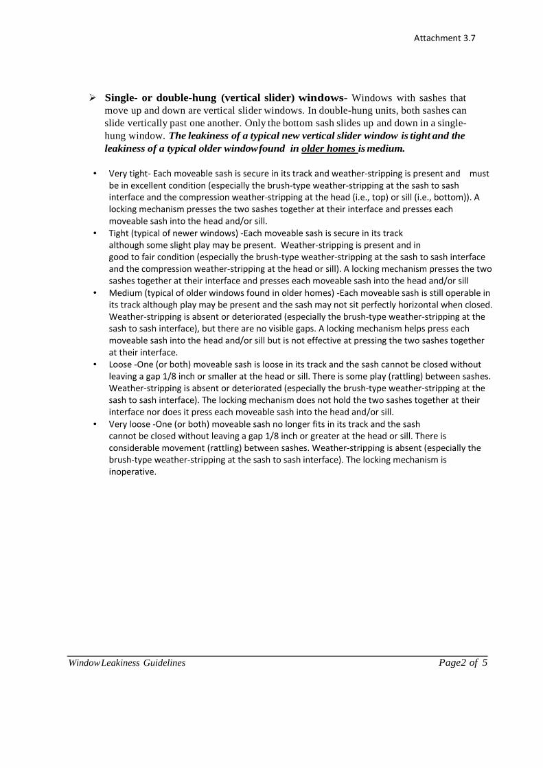
Page2 of 5 Window Leakiness Guidelines
Attachment 3.7
� Single- or double-hung (vertical slider) windows- Windows with sashes thatmove up and down are vertical slider windows. In double-hung units, both sashes canslide vertically past one another. Only the bottom sash slides up and down in a single-hung window. The leakiness of a typical new vertical slider window is tight and theleakiness of a typical older window found in older homes is medium.
• Very tight- Each moveable sash is secure in its track and weather-stripping is present and must
be in excellent condition (especially the brush-type weather-stripping at the sash to sash
interface and the compression weather-stripping at the head (i.e., top) or sill (i.e., bottom)). A
locking mechanism presses the two sashes together at their interface and presses each
moveable sash into the head and/or sill.
• Tight (typical of newer windows) -Each moveable sash is secure in its track
although some slight play may be present. Weather-stripping is present and in
good to fair condition (especially the brush-type weather-stripping at the sash to sash interface
and the compression weather-stripping at the head or sill). A locking mechanism presses the two
sashes together at their interface and presses each moveable sash into the head and/or sill
• Medium (typical of older windows found in older homes) -Each moveable sash is still operable in
its track although play may be present and the sash may not sit perfectly horizontal when closed.
Weather-stripping is absent or deteriorated (especially the brush-type weather-stripping at the
sash to sash interface), but there are no visible gaps. A locking mechanism helps press each
moveable sash into the head and/or sill but is not effective at pressing the two sashes together
at their interface.
• Loose -One (or both) moveable sash is loose in its track and the sash cannot be closed without
leaving a gap 1/8 inch or smaller at the head or sill. There is some play (rattling) between sashes.
Weather-stripping is absent or deteriorated (especially the brush-type weather-stripping at the
sash to sash interface). The locking mechanism does not hold the two sashes together at their
interface nor does it press each moveable sash into the head and/or sill.
• Very loose -One (or both) moveable sash no longer fits in its track and the sash
cannot be closed without leaving a gap 1/8 inch or greater at the head or sill. There is
considerable movement (rattling) between sashes. Weather-stripping is absent (especially the
brush-type weather-stripping at the sash to sash interface). The locking mechanism is
inoperative.

Page3 of 5 Window Leakiness Guidelines
Attachment 3.7
� Horizontal slider windows -Windows with sashes that move sideways arehorizontal slider windows. Both sashes can slide horizontally past one another in adouble-sliding window, and only one sash slides in a single-sliding window. Slidingglass doors are included in this window type. Horizontal slider windows are usually alittle leakier than comparable vertical slider windows. The leakiness of a typicalhorizontal slider window is medium.
• Very tight -Each moveable sash is secure in its track and weather-stripping is present and must be in
excellent condition (especially the brush-type weather-stripping at the sash to sash interface and the
compression weather-stripping at the end jamb (i.e., side)). A locking mechanism presses the two
sashes together at their interface and presses each moveable sash into the end jamb.
• Tight -Each moveable sash is secure in its track although some slight play may
• be present. Weather-stripping is present and in good to fair condition (especially the brush-type
weather-stripping at the sash to sash interface and the compression weather-stripping at the end
jamb). A locking mechanism presses the two sashes together at their interface and presses each
moveable sash into the end jamb.
• Medium (typical) -Each moveable sash is still operable in its track although
• play may be present and the sash may not sit perfectly vertical when closed. Weather-stripping is
absent or deteriorated (especially the brush-type weather-stripping at the sash to sash interface),
but there are no visible gaps. A locking mechanism helps press each moveable sash into the end
jamb but is not effective at pressing the two sashes together at their interface.
• Loose- One (or both) moveable sash is loose in its track and the sash cannot be
• closed without leaving a gap 118 inches or smaller at the end jamb. There is some play (rattling)
between sashes. Weather-stripping is absent or deteriorated (especially the brush-type weather-
stripping at the sash to sash interface). The locking mechanism does not hold the two sashes
together at their interface nor does it press each moveable sash into the end jamb.
• Very loose -One (or both) moveable sash no longer fits in its track and the sash
• cannot be closed without leaving a gap 118 inch or larger at the end jamb. There is considerable
movement (rattling) between sashes. Weather-stripping is absent (especially the brush-type
weather-stripping at the sash to sash interface). The locking mechanism is inoperative.
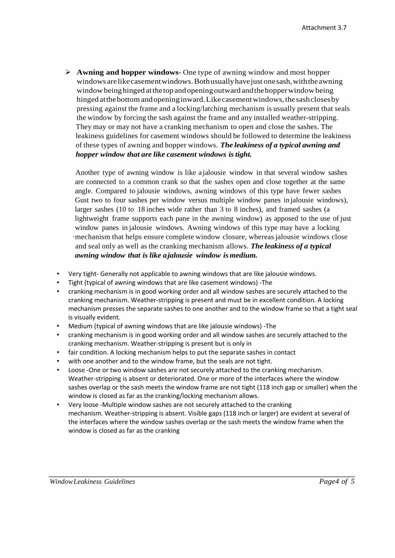
Page4 of 5 Window Leakiness Guidelines
Attachment 3.7
� Awning and hopper windows- One type of awning window and most hopperwindows are like casement windows. Both usually have just one sash, with the awningwindow being hinged at the top and opening outward and the hopper window beinghinged at the bottom and opening inward. Like casement windows, the sash closes bypressing against the frame and a locking/latching mechanism is usually present that sealsthe window by forcing the sash against the frame and any installed weather-stripping.They may or may not have a cranking mechanism to open and close the sashes. Theleakiness guidelines for casement windows should be followed to determine the leakinessof these types of awning and hopper windows. The leakiness of a typical awning andhopper window that are like casement windows is tight.
Another type of awning window is like a jalousie window in that several window sashesare connected to a common crank so that the sashes open and close together at the sameangle. Compared to jalousie windows, awning windows of this type have fewer sashesGust two to four sashes per window versus multiple window panes in jalousie windows),larger sashes (10 to 18 inches wide rather than 3 to 8 inches), and framed sashes (alightweight frame supports each pane in the awning window) as apposed to the use of justwindow panes in jalousie windows. Awning windows of this type may have a locking
·mechanism that helps ensure complete window closure, whereas jalousie windows closeand seal only as well as the cranking mechanism allows. The leakiness of a typicalawning window that is like a jalousie window is medium.
• Very tight- Generally not applicable to awning windows that are like jalousie windows.
• Tight (typical of awning windows that are like casement windows) -The
• cranking mechanism is in good working order and all window sashes are securely attached to the
cranking mechanism. Weather-stripping is present and must be in excellent condition. A locking
mechanism presses the separate sashes to one another and to the window frame so that a tight seal
is visually evident.
• Medium (typical of awning windows that are like jalousie windows) -The
• cranking mechanism is in good working order and all window sashes are securely attached to the
cranking mechanism. Weather-stripping is present but is only in
• fair condition. A locking mechanism helps to put the separate sashes in contact
• with one another and to the window frame, but the seals are not tight.
• Loose -One or two window sashes are not securely attached to the cranking mechanism.
Weather-stripping is absent or deteriorated. One or more of the interfaces where the window
sashes overlap or the sash meets the window frame are not tight (118 inch gap or smaller) when the
window is closed as far as the cranking/locking mechanism allows.
• Very loose -Multiple window sashes are not securely attached to the cranking
mechanism. Weather-stripping is absent. Visible gaps (118 inch or larger) are evident at several of
the interfaces where the window sashes overlap or the sash meets the window frame when the
window is closed as far as the cranking

Page5 of 5 Window Leakiness Guidelines
Attachment 3.7
mechanism allows. The locking mechanism is inoperative or does not help press the sashes
together or into the frame.
� Jalousie windows -Jalousie windows are louvered windows, typically constructedof multiple horizontal panes (usually about 3 to 8 inches wide) that all open at thesame angle when a crank near the bottom of the window is turned. The leakiness ofa typical jalousie window is loose.
• Very tight- Generally not applicable to jalousie windows.
• Tight- Generally not applicable to jalousie windows.
• Medium -The cranking mechanism is in good working order, all window panes are securely
attached to the cranking mechanism, and a tight glass to glass seal is visually obtained at the
overlap of all windows panes.
• Loose (typical) -One or two window panes are not securely attached to the
cranking mechanism, or one or more of the glass to glass interfaces where the window panes
overlap are not tight when the window is closed as far as the cranking mechanism allows.
• Very loose -Multiple window panes are not securely attached to the cranking mechanism, or
visible gaps are evident at several of the glass to glass interfaces where the window panes
overlap when the window is closed as far as the cranking mechanism allows.
The guidance provided above based on window type should be modified as follows to take into account the condition of the window panes and the presence of storm windows:
� Window panes tightness- Degrade the leakiness description one level if the window. panes themselves have become significantly loose in their mounting and/or a small
(i.e., half-dollar-sized) piece of window is broken out. Degrade the leakiness twolevels if there is a larger hole in a window pane and/or an entire pane is missing.
� Storm window presence- Upgrade the leakiness description one level if astorm window in average or better condition is installed.

Attachment 3.8
Energy Star Equipment Specifications
Furnaces and Boilers: • Gas Furnaces
o Rating of 95% AFUE or greatero Less than or equal to 2.0% furnace fan efficiencyo Less than or equal to 2.0% air leakage
• Oil Furnaceso Rating of 85% AFUE or greatero Less than or equal to 2.0% furnace fan efficiencyo Less than or equal to 2.0% air leakage
• Boilerso Rating of 85% AFUE or greater
Air Source Heat Pumps: • Split Systems
o 8.2 HSPF or greatero 14.5 SEER or greater
• Package Unitso 8.0 HSPF or greatero 14.0 SEER or greater
Central Air Conditioners: • Split Systems
o 14.5 SEER or greater• Package Units
o 14.0 SEER or greater
Room or Window Air Conditioners: Units Without Reverse Cycle
Capacity (Btu/Hr) ENERGY STAR EER, with louvered sides
ENERGY STAR EER, without louvered sides
< 6,000 ≥ 11.2 ≥ 10.4
6,000 to 7,999 8,000 to 10,999
≥ 11.3
≥ 9.8 11,000 to 13,999 14,000 to 19,999 ≥ 11.2 20,000 to 27,999
≥ 9.8 ≥ 28,000
Units With Reverse Cycle
Capacity (Btu/Hr) ENERGY STAR EER, with louvered sides
ENERGY STAR EER, without louvered sides
< 14,000 N/A
≥ 9.8 ≥ 14,000 ≥ 9.2 < 20,000 ≥ 10.4
N/A ≥ 20,000 ≥ 9.8
Casement ENERGY STAR EER Casement-only ≥ 10.0 Casement-slider ≥ 10.9
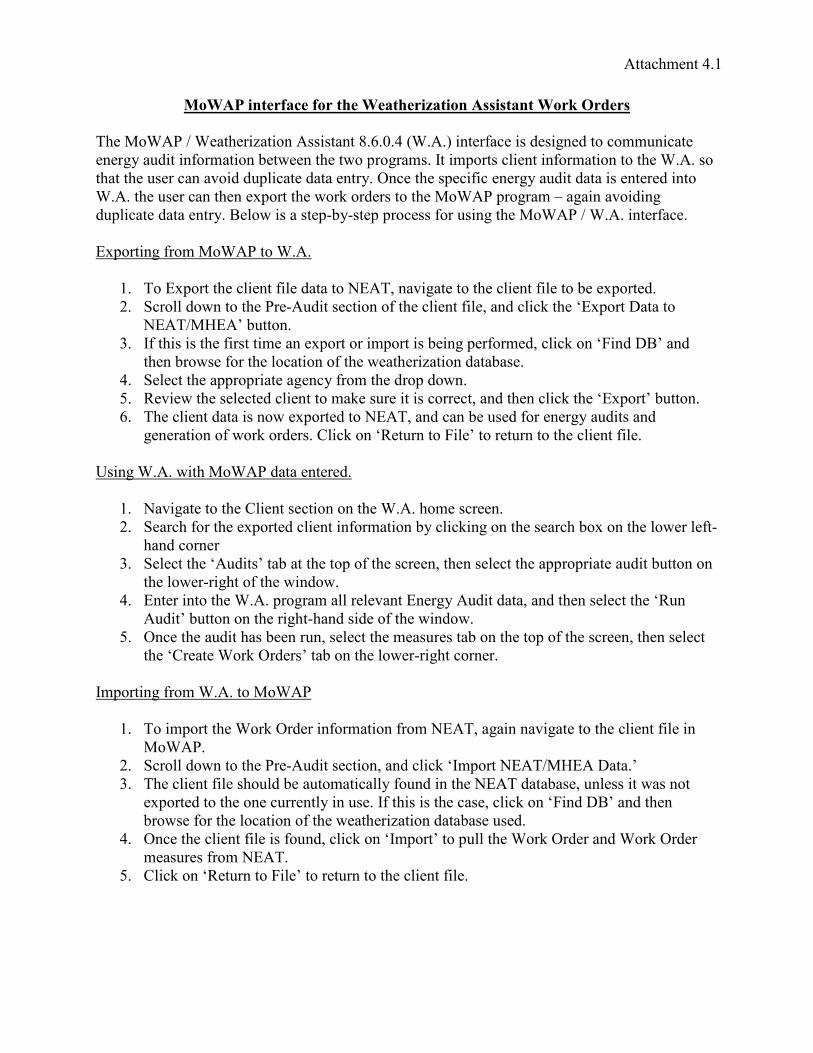
Attachment 4.1
�1����-&'%�2��%�21��'�%��%�'�%�-:�'-1&��**-*'�&'��1�4��(%�*�
���/�+���+�����&$,��$���(($(����0 � � 9�+ � �$���&)���$("�($'��"������ �$����
���&'%� "$�$�)�&���$��.��*�������*�!&�'&��( ��$�!�&�(�#$���$�)�&���$�������+ � (�
������� (�&����-�$"" !#$����"������&% �������(!��$)$����&'%� "$�"���$(����&�"$���
+ � ��� (�&��������6!�&����*�&5�&"�&(�����/�+��!&�'&��L�'�$��-�$"$�'
" !#$����"������&% A�#�*$(�(��!�.%�(��!!&���(()�& ($�'���/�+���+ � $���&)���
�6!�&�$�')&��/�+����+ �
� � ���6!�&�����#$���)$#�"�����>���1��-$'���������#$���)$#���.��6!�&��"
� � ��&�##"�*�������&��� "$�(���$���)����#$���)$#�1��"�#$�5���M�6!�&�3�����
>����/���H. ����
� �)��$($(���)$&(��$�����6!�&��&$�!�&�$(.�$�'!�&)�&��"1�#$�5��M8$�"3AH��"
����.&�*(�)�&���#����$���)���*�����&$,��$��"���.�(�
9 � ��#�������!!&�!&$����'���%)&�����"&�!"�*�
B � ��-$�*���(�#����"�#$�������5�( &�$�$(��&&���1��"�����#$�5���M�6!�&�H. ����
� � ����#$���"���$(��*�6!�&��"��>���1��"���.� (�")�&���&'%� "$�(��"
'���&��$���)*�&5�&"�&( �#$�5��M��� &���8$#�H��&�� &�������#$���)$#�
;($�'+ � *$��/�+��"�������&�"
� � >�-$'���������#$���(���$�������+ � ����(�&���
� � ���&��)�&����6!�&��"�#$���$�)�&���$��.%�#$�5$�'�����(��&��.�6�����#�*�&#�)��
���"��&��&
� ��#������M� "$�(H��.�������!�)���(�&���1����(�#�������!!&�!&$���� "$�. ������
���#�*�&�&$'���)���*$�"�*
9 � ����&$������+ � !&�'&���##&�#�-������&'%� "$�"���1��"����(�#������M� �
� "$�H. ���������&$'������"($"��)���*$�"�*
B � �������� "$���(.���& �1(�#���������( &�(��.�������!�)���(�&���1����(�#���
���M�&����+�&5�&"�&(H��.�����#�*�&�&$'����&��&
��!�&�$�')&��+ � ��/�+��
� � ��$�!�&����+�&5�&"�&$�)�&���$��)&��>���1�'�$���-$'���������#$���)$#�$�
/�+��
� � ��&�##"�*�������&��� "$�(���$��1��"�#$�5M��!�&�>����/���3��� H
� ����#$���)$#�(�� #".�� �����$��##%)� �"$����>���"���.�(�1 �#�(($�*�(���
�6!�&��"��������� &&���#%$� (� �)��$($(�����(�1�#$�5��M8$�"3AH��"����
.&�*(�)�&���#����$���)���*�����&$,��$��"���.�(� (�"
9 � ��������#$���)$#�$()� �"1�#$�5��M��!�&�H��! ##���+�&5�&"�&��"+�&5�&"�&
���( &�()&��>���
B � �#$�5��M��� &���8$#�H��&�� &�������#$���)$#�

Attachment 4.2
�������������� ������������ ����������������
������������ �����
��������������������� ���!������"������������#���������$"������������#�"�������
%��"�������&�������'"��(�##�������"���������������'"���������#��"����
�!����)������
*'���!�������!��������������������#������+����!������������������)�������"#������
��#��!#����,�"�"�����&&-���"./�0
1111111111&&-��2�,./�3&&-��41111111111./������
!�
*'���!�������!��������������������"���#�������� � +������#���+!�"!����+����!���������������
���)�������"#���01111111111&&-�������
�!����$""#���
����!������������������$""#����"#���01111111111./������
5����������%�'�������"��
����!����������'"��###������������'�������"�����������������-���#"���"#���0
1111111111./������
/�����)������
*'����"�(�������������#������+����!����������'"��##(����������������������������-���#"��
�"#���01111111111./������
!�
*'����"�(�������������"���#�������� � +������#���+!�"!����+����!����������'"��##(�����
�����������������������-���#"���"#��������#��!#���� �����"�"�����./��"&&-��0
1111111111./�2� ����&&-��3./�41111111111&&-�������
"��#)"���
����!���&&-�����./�����������������'"��!�����������+�!�����""#���+#����������
��'�������"��+���(������������+�����#��!#���� 67�"���"���'"���� 8�"���!�������"�����������
�"������������"��#�������'"�����"���0
1111111111&&-��2� 6741111111111�"��#&&-�������
1111111111./�2� 6741111111111�"��#./������
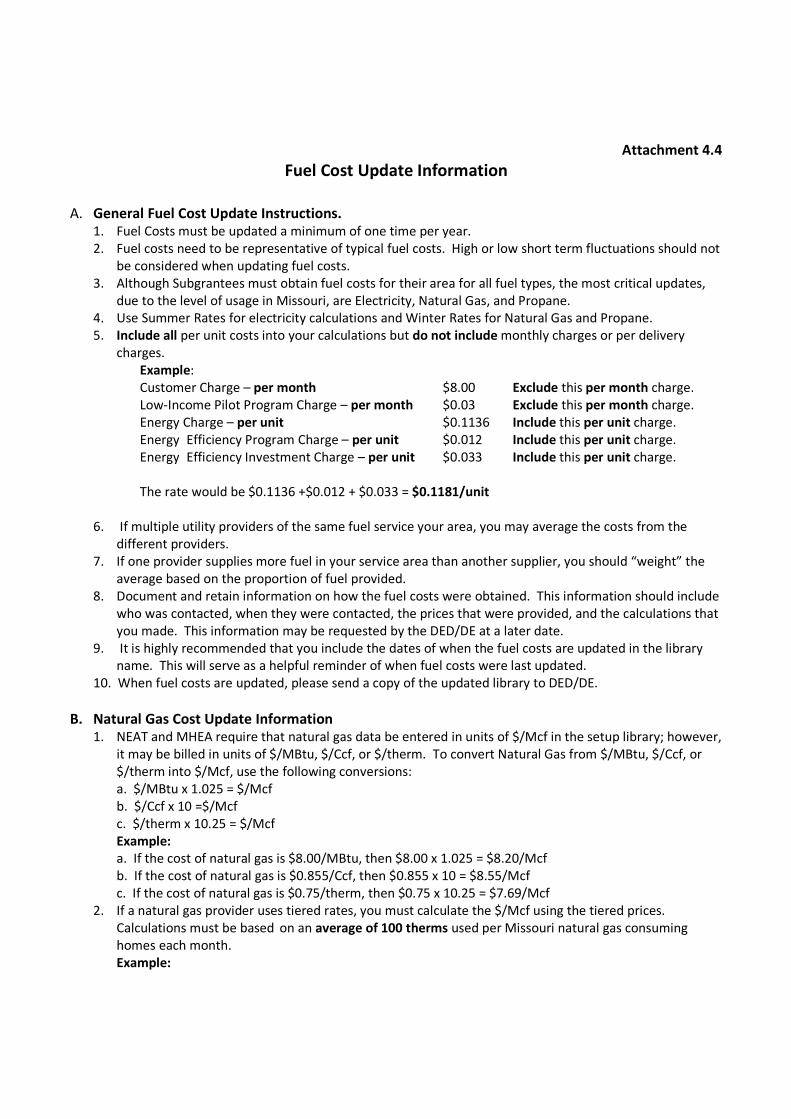
Attachment 4.4
Fuel Cost Update Information
A. General Fuel Cost Update Instructions. 1. Fuel Costs must be updated a minimum of one time per year.
2. Fuel costs need to be representative of typical fuel costs. High or low short term fluctuations should not
be considered when updating fuel costs.
3. Although Subgrantees must obtain fuel costs for their area for all fuel types, the most critical updates,
due to the level of usage in Missouri, are Electricity, Natural Gas, and Propane.
4. Use Summer Rates for electricity calculations and Winter Rates for Natural Gas and Propane.
5. Include all per unit costs into your calculations but do not include monthly charges or per delivery
charges.
Example:
Customer Charge – per month $8.00 Exclude this per month charge.
Low-Income Pilot Program Charge – per month $0.03 Exclude this per month charge.
Energy Charge – per unit $0.1136 Include this per unit charge.
Energy Efficiency Program Charge – per unit $0.012 Include this per unit charge.
Energy Efficiency Investment Charge – per unit $0.033 Include this per unit charge.
The rate would be $0.1136 +$0.012 + $0.033 = $0.1181/unit
6. If multiple utility providers of the same fuel service your area, you may average the costs from the
different providers.
7. If one provider supplies more fuel in your service area than another supplier, you should “weight” the
average based on the proportion of fuel provided.
8. Document and retain information on how the fuel costs were obtained. This information should include
who was contacted, when they were contacted, the prices that were provided, and the calculations that
you made. This information may be requested by the DED/DE at a later date.
9. It is highly recommended that you include the dates of when the fuel costs are updated in the library
name. This will serve as a helpful reminder of when fuel costs were last updated.
10. When fuel costs are updated, please send a copy of the updated library to DED/DE.
B. Natural Gas Cost Update Information 1. NEAT and MHEA require that natural gas data be entered in units of $/Mcf in the setup library; however,
it may be billed in units of $/MBtu, $/Ccf, or $/therm. To convert Natural Gas from $/MBtu, $/Ccf, or
$/therm into $/Mcf, use the following conversions:
a. $/MBtu x 1.025 = $/Mcf
b. $/Ccf x 10 =$/Mcf
c. $/therm x 10.25 = $/Mcf
Example:
a. If the cost of natural gas is $8.00/MBtu, then $8.00 x 1.025 = $8.20/Mcf
b. If the cost of natural gas is $0.855/Ccf, then $0.855 x 10 = $8.55/Mcf
c. If the cost of natural gas is $0.75/therm, then $0.75 x 10.25 = $7.69/Mcf
2. If a natural gas provider uses tiered rates, you must calculate the $/Mcf using the tiered prices.
Calculations must be based on an average of 100 therms used per Missouri natural gas consuming
homes each month.
Example:
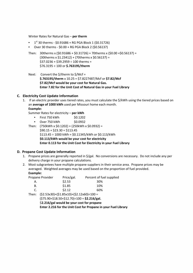
Winter Rates for Natural Gas – per therm
• 1st 30 therms - $0.91686 + RG PGA Block 1 ($0.31726)
• Over 30 therms - $0.00 + RG PGA Block 2 ($0.56137)
Then: 30therms x ($0.91686 + $0.31726) + 70therms x ($0.00 +$0.56137) =
(30therms x $1.23412) + (70therms x $0.56137) =
$37.0236 + $39.2959 ÷ 100 therms =
$76.3195 ÷ 100 or $.763195/therm
Next: Convert the $/therm to $/Mcf =
$.763195/therm x 10.25 = $7.8227487/Mcf or $7.82/Mcf
$7.82/Mcf would be your cost for Natural Gas.
Enter 7.82 for the Unit Cost of Natural Gas in your Fuel Library
C. Electricity Cost Update Information 1. If an electric provider uses tiered rates, you must calculate the $/kWh using the tiered prices based on
an average of 1000 kWh used per Missouri home each month.
Example:
Summer Rates for electricity – per kWh
• First 750 kWh $0.1202
• Over 750 kWh $0.0932
Then: (750kWh x $0.1202) + (250kWh x $0.0932) =
$90.15 + $23.30 = $113.45
$113.45 ÷ 1000 kWh = $0.11345/kWh or $0.113/kWh
$0.113/kWh would be your cost for electricity
Enter 0.113 for the Unit Cost for Electricity in your Fuel Library
D. Propane Cost Update Information 1. Propane prices are generally reported in $/gal. No conversions are necessary. Do not include any per
delivery charge in your propane calculations.
2. Most subgrantees have multiple propane suppliers in their service area. Propane prices may be
averaged. Weighted averages may be used based on the proportion of fuel provided.
Example:
Propane Provider Price/gal. Percent of fuel supplied
A. $2.53 30%
B. $1.85 10%
C. $2.12 60%
Then: ($2.53x30)+($1.85x10)+($2.12x60)÷100 =
($75.90+$18.50+$12.70)÷100 = $2.216/gal.
$2.216/gal would be your cost for propane
Enter 2.216 for the Unit Cost for Propane in your Fuel Library

1
Attachment 5.1
DED/DE Multi-Family Submittal Information Requirements:
I. General Project Narrative
A. Information to include in the narrative
1. Age of the building(s)
2. Condition of the building(s):
Site general information, but do provide some detail into the reasoning of why the
building(s) is/are considered to be in said condition.
3. Number of units:
a. Total number of units in all buildings
b. Number of units in each building
4. Spatial orientation of all buildings:
DED/DE will need individual TREAT/NEAT evaluation for each building to be
weatherized
5. Heating and cooling types:
Description of how units are heated and cooled
a. Is there a central distribution system for all units, if so what kind?
b. Is each unit individually heated and cooled, if so what kind of system for each
unit?
c. What is/are the conditions(s) of the heating and cooling system(s) for the units?
6. Health and safety concerns:
List and describe any health and safety concerns that are being proposed to be
addressed with WAP funding
7. Other notable conditions:
Include any additional information that is pertinent to the evaluation and
weatherization of the building(s) and/or units.
B. General narrative information
1. A 1 to 2 page narrative should be sufficient
2. The narrative should paint a verbal picture. Use the narrative to describe the project
for the perspective of someone who will not be on-site.
3. The additional information outside of the narrative should be used as supporting
information to the narrative, not as a substitute for the narrative.
II. Building Assessment
A. List of assessments to submit
1. Lighting inventory assessment
2. Heating and cooling equipment and controls
3. Water heating equipment and controls
4. Air leakage determination:
Provide a description of how air leakage was determined.
5. Combustion testing:
a. Provide all testing results from testing of all combustion appliances
b. Include CO and worst case draft tests
6. Insulation assessment:

Page 2 of 3
e. Combustion Testingi. Provide all testing results from testing of all combustion `` ` ` `` `````appliancesii. Include CO and CAZ tests
f. Insulation Assessmenti. Include type of insulation and level/amount of insulationii. If vermiculite is present, what will be done (testing, etc)
g. Baseload Assessmenti. Provide assessment information and description of how ` `````information was obtained
h. Door and Window Assessmenti. Detailed information will be needed for any doors or windows to ``` be replacedii. Note: DED/DE policy of more than two windows to be installed `````requires DED/DE approval if more than two windows are being ``` installed per building` (not per unit)
i. Health and Safety Assessmentj. Any Additional Assessments
2. Assessment Informationa. Provide any and all forms used in the assessment and evaluation of the` building(s) and unitsb. Much of this information can be provided in a narrative
i. Reference associated forms within the narrativec. TREAT/NEAT audits should be supporting to narrative and submitted
assessmentsIII. Additional Information
1. Additional Information to Submita. Photographs of the Building
i. Photographs shall include the exterior and interior of the building1. Photographs of every issue are not necessary, but the ```` submitted photographs need to convey the issues of the ``` building and necessity of work to be performed
ii. Photographs need to be submitted in color and can be emailed ``` separately, if necessary
b. Weatherization Statement of Worki. Includes all work orders/scopes developed to be given to ````crew/contractorsii. TREAT printouts are not acceptable in lieu of a work orderiii. NEAT Recommended Measures printout is not acceptable in lieu````of a work order
c. Project Timelined. Projected Costs and Associated SIR
i. Costs must include both labor and materialsii. TREAT/NEAT printouts will suffice
Attachment 5.1

Page 3 of 3
1. Must show individual measure SIR and cumulative SIRe. Documentation for Landlord Contribution
i. Documentation showing amount of contributions and the```percentage of the contribution
f. Buy-down Documentationi. Buy-down is only acceptable in multi-familyii. Buy-down cannot be part of the landlord contribution
g. Complete Copy of the Computerized Auditi. Must provide a copy of all the inputs and outputs of the `````computerized auditii. Include a narrative describing the methodology used to assess `````the building(s)
1. Describe that each building was assessed individuallya. Note: DED/DE will need individual TREAT/NEAT````evaluations for each building to be weatherized
iii. If an engineering assessment is done, then the assessment and````narrative from the engineering firm must be provided
Additional Notes Regarding Multi-Family Submittals must be in electronic format, with PDF being the preferred format
° Hard copy submittals may be submitted with prior approval from DED/DE Additional information, on top of the above information, may be required on a case``````by case basis during the submittal review by DED/DE and/or DOE If an engineer is used for the evaluation of a measure, the cost of the engineer must``````be included in the cost of the measure Number of Units Breakdown for Required Approval and Computerized Audits:
° TREAT can be used for Multi-Family with 5-25 units that have individual ````````````HVAC systems, but will require DED/DE and DOE approval prior to ````````````work commencing
DED/DE and DOE may require on-site visits as part of the evaluation of the``````submittal Send submittals to Todd McVicker and Kevin Scherr
° All DOE reviews of multi-family projects will be submitted by the ``DED/DE
Number of Units per Building
TREAT or
NEAT Approval Prior to Work
DNR DOE
1-4 NEAT NO NO
5-25 (individual HVAC/unit) NEAT Yes Yes5-25 ( not individual HVAC/unit) TREAT Yes Yes
Greater than 25 TREAT Yes Yes
Attachment 5.1
If you have any questions, please contact Todd McVicker and/or Kevin Scherr [email protected] or 573-751-7158 and at [email protected] or 573-751-6659. [email protected] or 573-526-4209
Attachment 5.1
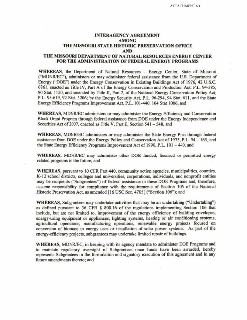
ATTACHMENT 6.1

Attachment 6.1

Attachment 6.1

Attachment 6.1

Attachment 6.1
Attachment 6.1
Attachment 6.1
Attachment 6.1
Attachment 6.1

Attachment 6.1

Attachment 6.1

Attachment 6.1
Attachment 6.1

Attachment 6.1

Attachment 6.1

Attachment 6.1

�
Atta
chm
ent 6
.1

����������6-2
�������������������� ���������������������
������������
�
�������������������� �����������������������������������������
��������������������������������������������������������
��������������������������������������������������������
���� !!��������
���������������������"������������������"��������������
������#����������������"���������������������������������
������������ ���� ����������������
�������������������������������� �������������������� ������������������
�
������������������������������������������������"������
������������"������������������������
�
�� �������������$������%���"�&��������������������������������
�� ����������������������������������������������"������
������������"����������������������������������������
�� �������������������������������������������������
�� ����������������������"��������������������������� �������������
�
�� ��������������������������������������������"������
������������������������ ������������������������������
�� �������� ��������"��������������
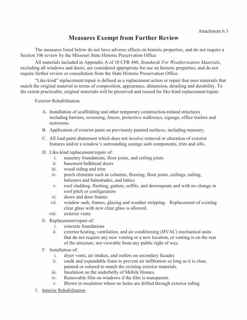
����������6.3�%�*0�%*��6%3)'�2�13��0�'�%���%+-%8�
�
������( &�(#$(��".�#�*"������-��"-�&(��))���(���$(��&$�!&�!�&�$�(1��""����&�4 $&��
����$�����&�-$�*.%���/$((� &$������$(��&$��&�(�&-��$���))$��
�##����&$�#($��# "�"$��!!��"$6��)���8�99�1���������������� ������������������1
�6�# "$�'�##*$�"�*(��""��&(1�&����($"�&�"�!!&�!&$���)�& (����$(��&$�!&�!�&�$�(1��""����
&�4 $&�) &���&&�-$�*�&���( #���$��)&�����������$(��&$��&�(�&-��$���))$��
O�$5��5$�"P&�!#��������&�!�$&$("�)$��"�(�&�!#����������$���&&�!�$&���� (�(����&$�#(����
���������&$'$��#����&$�#$���&�(�)���!�($�$��1�!!��&����1"$���($��1"���$#$�'��"" &�.$#$�% ��
����6����!&���$��.#�1�&$'$��#����&$�#(*$##.�!&�(�&-�"��"&� (�")�&#$5��5$�"&�!#��������&�!�$&
�6��&$�&����.$#$���$��
� � ��(��##��$���)(��))�#"$�'��"����&���!�&�&%���(�& ��$���&�#���"(�& �� &�(
$��# "$�'.�&&$�&(1(�&���$�'1)����(1!&�����$-�*�#5*�%(1($'��'�1�))$���&�$#�&(��"
&�(�&���(
A � �!!#$���$���)�6��&$�&!�$����!&�-$� (#%!�$���"( &)���(1$��# "$�'��(��&%
� � �###��"!�$���.�������*�$��"��(���$�-�#-�&���-�#�&�#��&��$���)�6��&$�&
)��� &�(��"��&�*$�"�*H(( &&� �"$�'��($�'((�(����!�����(1�&$���"($##(
3 � �$5��5$�"&�!#��������&�!�$&�)?
$ � ��(��&%)� �"��$��(1)#��&<�$(�(1��"��$#$�'<�$(�(
$$ � .�(�����. #5���""��&(
$$$ � *��"($"$�'��"�&$�
$- � !�&���#�����(( ���(��# ��(1)#��&$�'1)#��&<�$(�(1��$#$�'(1&�$#$�'1
.�# (��&(��".�# (�&�"�(1��"#���$��
- � &��)�#�""$�'1)#�(�$�'1' ���&(1(�))$�(1��""�*�(!� �(��"*$��������'�$�
&��)!$����&���)$' &��$��
-$ � "��&(��""��&)&���(
-$$ � *$�"�*(�(�1)&���(1'#�,$�'��"*�����&(�&$!!$�' ��!#��������)�6$(�$�'
�#��&'#�((*$����*�#��&'#�(($(�##�*�"
-$$$ � �6��&$�&-���(
� � ��!#��������&�!�$&�)?
$ � ����&���)� �"��$��(
$$ � �6��&$�&����$�'1-���$#��$��1��"�$&���"$�$��$�'��7���������$��# �$�(
����"����&�4 $&���%��*-���$�'�&���*#����$��1�&-���$�'$(�����&��&
�)���(�& �� &�1���-$�*�.#�)&����%! .#$�&$'���)*�%
8 � ��(��##��$���)?
$ � "&%�&-���(1�$&$���5�(1��"� �#��(��(����"�&%)���"�(
$$ � �� #5��"�6!��"�.#�)�����!&�-����$&$�)$#�&��$��(�#��'�($�$(�#��&1
!�$���"�&��#�&�"�����������6$(�$�'�6��&$�&����&$�#(
$$$ � ��( #��$������� �"�&.�##%�)/�.$#�����(
$- � ����-�.#�)$#���*$�"�*($)���)$#�$(�&��(!�&���
- � A#�*�$�$�( #��$��*��&�����#�(�&�"&$##�"��&� '��6��&$�&($"$�'
� � ����&$�&����.$#$���$��

� � ����&$�&$�!&�-�����(��"&���.$#$���$��*��&���(�& �� &�#�#��&��$��(�&���"�1
*��&���"���#$�$���)*�##(1��$#$�'(��"��&)#��&(��� &(1��"*��&���"&�!��$#$�'(
�&��""�"�&*�##(�&�) &&�"� ��&��-�"1��"���($(�$�'�)?
$ � !# �.$�'*�&51$��# "$�'$�(��##��$���)*���&�����&(
$$ � �#���&$��#*�&51$��# "$�'$�!&�-$�'#��!�))$�$���%
$$$ � ����$�'1-���$#��$��1��"�$&���"$�$��$�'��7���(%(���(��"���$&
���!�����(
$- � $�( #��$��$�(��##��$��$����$�(��"�&�*#(!���(
- � .#�*�$�$�( #��$��*��&���"���&��$-�!#�(��&$("���'�"
A � �$5��5$�"&�!#��������&�!�$&�)?
$ � !#�(��&*�##(��"��$#$�'(
$$ � )#��&(1$��# "$�'&�)$�$(�$�'
� � ��(��##��$���)"&%*�##*��&��&$'$��#!#�(��&*�##( &)���(�&��$(($�'1��"*�$��*$##
����!!&��$�.#%����'�����&$�!&�)$#� >�"���&��$-�!#�(��&�&����&"���&��$-�
)��� &�((��##.���-�&�"
3 � �##!�$��$�'��"��&!��$�'1!&�-$"�"������&!��$�'$�(��##��$��"���'�(�� �"�&#%$�'
*��"�&��(��&%)#��&( &)���(
� � �##5$�������".���&���&���"�#$�'1!&�-$"�"��*�##(1*$�"�*(1�&"��&(�&�
�#��&�"
8 � �###��"!�$���.�������*�$��"��(���$�-�#-�&���-�#�&�#��&��$���)$���&$�&
)��� &�(
= � �##�(.�(��(�.�������*�$��"��(���$�-�#-�&���-�#�&�#��&��$���)$���&$�&
)��� &�(
� � �4 $!����
����"�&"���&'%�))$�$���%���( &�(����"����&�4 $&�'&� �""$(� &.�����&&�#����$���&
&���-�#�)*�##(1��$#$�'(�&)#��&(1( ���(1. ����#$�$��"��?$�(��##��$���&&�!#��������)
����&(1#$'��$�'1.#�*�&(1! �!(1����$�'1-���$#��$��1��"�$&���"$�$��$�'��7���(%(���(
����"����&�4 $&���%��*-���$�'�&���*#����$��1�&-���$�'$(�����&��&�)���(�& �� &�1
���-$�*�.#�)&����%! .#$�&$'���)*�%

MISSOURI DEPARTMENT OF NATURAL RESOURCES STATE HISTORIC PRESERVATION OFFICE SECTION 106 PROJECT INFORMATION FORM
Submission of a completed Project Information Form with adequate information and attachments constitutes a request for a review pursuant to Section 106 of the National Historic Preservation Act of 1966 (as amended). We reserve the right to request more information. Please refer to the CHECKLIST on Page 2 to ensure that all basic information relevant to the project has been included. For further information, refer to our website at: http://dnr.mo.gov/shpo and follow the links to Section 106 Review.
NOTE: Section 106 regulations provide for a 30-day response time by the Missouri State Historic Preservation Office from the date of receipt.
PROJECT NAME
FEDERAL AGENCY PROVIDING FUNDS, LICENSE, OR PERMIT
APPLICANT TELEPHONE
CONTACT PERSON TELEPHONE
ADDRESS FOR RESPONSE
LOCATION OF PROJECT COUNTY
STREET ADDRESS CITY
LEGAL DESCRIPTION OF PROJECT AREA (TOWNSHIP, RANGE, SECTION, ¼ SECTION) USGS TOPOGRAPHIC MAP QUADRANGLE NAME (SEE MAP REQUIREMENTS ON PAGE 2)
YEAR TOWNSHIP RANGE SECTION
PROJECT DESCRIPTION DESCRIBE THE OVERALL PROJECT IN DETAIL. IF IT INVOLVES EXCAVATION, INDICATE HOW WIDE, HOW DEEP, ETC. IF THE PROJECT INVOLVES DEMOLITION OF EXISTING BUILDINGS, MAKE THAT CLEAR. IF THE PROJECT INVOLVES REHABILITATION, DESCRIBE THE PROPOSED WORK IN DETAIL. USE ADDITIONAL PAGES IF NECESSARY.
Attachment 6.4

ARCHAEOLOGY (EARTHMOVING ACTIVITIES) HAS THE GROUND INVOLVED BEEN GRADED, BUILT ON, BORROWED, OR OTHERWISE DISTURBED? PLEASE DESCRIBE IN DETAIL (USE ADDITIONAL PAGES, IF NECESSARY) PHOTOGRAPHS ARE HELPFUL:
WILL THE PROJECT REQUIRE FILL MATERIAL? YES NO IF YES, INDICATE PROPOSED BORROW AREAS (SOURCE OF FILL MATERIAL) ON TOPOGRAPHIC MAP
ARE YOU AWARE OF ARCHAEOLOGICAL SITES ON OR ADJACENT TO PROJECT AREA? YES NO IF YES, IDENTIFY THEM ON THE TOPOGRAPHIC MAP
STRUCTURES (REHABILITATION, DEMOLOTION, ADDITIONS TO, OR CONTRUCTION NEAR EXISTING STRUCTURES) TO THE BEST OF YOUR KNOWLEDGE, IS THE STRUCTURE LOCATED IN ANY OF THE FOLLOWING?
AN AREA PREVIOUSLY SURVEYED A NATIONAL REGISTER DISTRICT A LOCAL HISTORIC DISTRICT
FOR HISTORIC PROPERTIES.
IF YES, PLEASE PROVIDE THE NAME OF IF YES, PLEASE PROVIDE THE NAME OF IF YES, PLEASE PROVIDE THE NAME OF THE SURVEY OR DISTRICT: THE SURVEY OR DISTRICT: THE SURVEY OR DISTRICT:
• PLEASE PROVIDE PHOTOGRAPHS OF ALL STRUCTURES, SEE PHOTOGRAPHY REQUIREMENTS • NOTE: ALL PHOTOGRAPHS SHOULD BE LABELED AND KEYED TO ONE MAP OF THE PROJECT AREA • PLEASE PROVIDE A BRIEF HISTORY OF THE BUILDING(S), INCLUDING CONSTRUCTION DATES AND BUILDING USES. (USE
ADDITONAL PAGES, IF NECESSARY.) ADDITIONAL REQUIREMENTS Map Requirements: Attach a copy of the relevant portion (8 ½ x 11) of the current USGS 7.5 min. topographic map and, if necessary, a large scale project map. Please do not send an individual map with each structure or site. While an original map is preferable, a good copy is acceptable. For a list of sites from which to order, download or print the required USGS 7.5 min. topographic maps at little or no cost, consult http://dnr.mo.gov/shpo/sectionrev.htm .
Photography Requirements: Clear black and white or color photographs (minimum 3” x 5”) are acceptable. Polariods, photocopies, emailed or faxed photographs are not acceptable. Good quality photographs are important for expeditious project review. Photographs of neighboring or nearby buildings are also helpful. All photographs should be labeled and keyed to one map of the project area. CHECKLIST-DID YOU PROVIDE THE FOLLOWING INFORMATION?
Topographic map 7.5 min. (per project, not structure) Other supporting documents (If necessary to explain the project)
Thorough description (all projects) For new construction, rehabilitations, etc., attach work write-ups, plans, drawings, etc.
Photographs (all structures) Is topographic map identified by quadrangle and year?
Return this Form and Attachments to:
MISSOUR DEPARTMENT OF NATURAL RESOURCES STATE HISTORIC PRESERVATION OFFICE Attn: Section 106 Review P.O. BOX 176 JEFFERSON CITY, MISSOURI 65102-0176
780-1027(08-09)