nefton technologies - mettler toledo multirange id7sx … · respective guide for installers and...
TRANSCRIPT
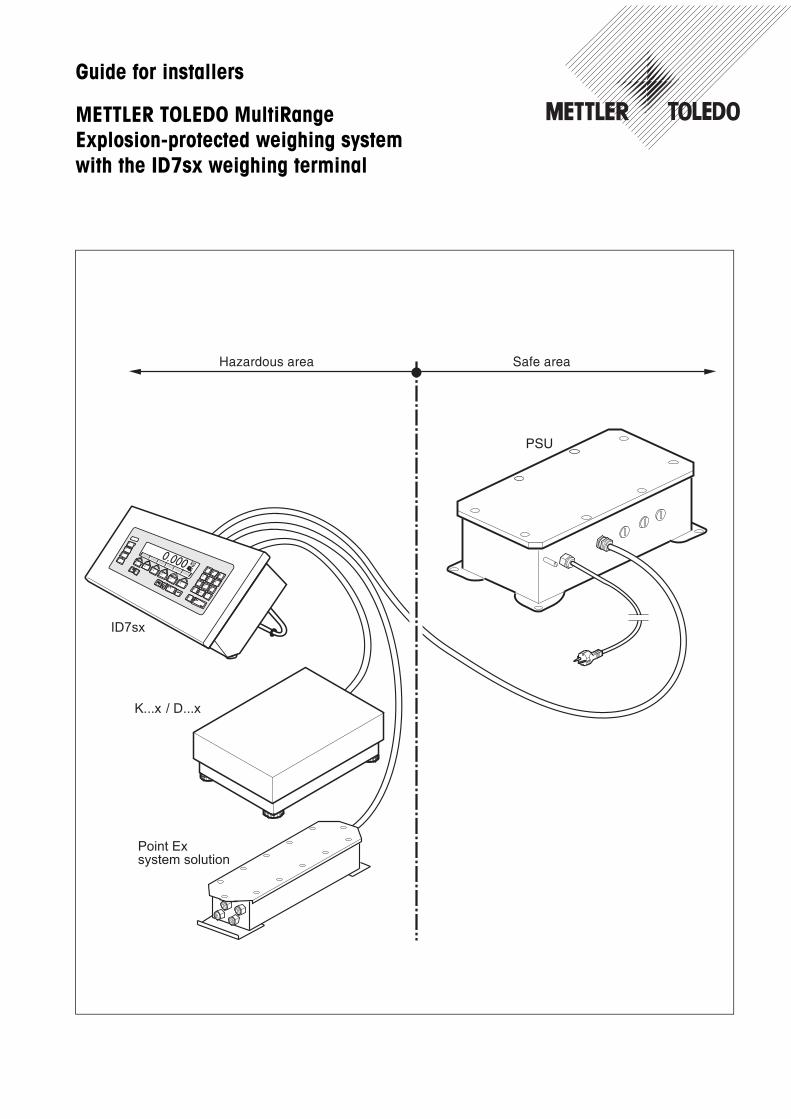
Guide for installers
METTLER TOLEDO MultiRangeExplosion-protected weighing systemwith the ID7sx weighing terminal

Contents
Guide for installers 22008316B 04/09 1
ID7sx
Contents Page
1 Safety instructions ....................................................................... 2
2 System overview ......................................................................... 32.1 Typical configurations ................................................................... 32.2 Description of the components ....................................................... 6
3 Installation.................................................................................. 73.1 Setting up system modules ............................................................ 73.2 Connecting devices ....................................................................... 103.3 Selecting peripheral devices ........................................................... 113.4 Equipotential bonding ................................................................... 123.5 Connecting power supply .............................................................. 12
4 Optional work .............................................................................. 134.1 Making connection cables ............................................................. 134.2 Installing additional scale interface or active CL/IDNet module............ 144.3 Installing memory module ............................................................. 164.4 Installing additional data interface................................................... 174.5 Installing digital inputs/outputs ....................................................... 184.6 Connecting barcode scanner .......................................................... 194.7 Attaching Profibus-DP module........................................................ 20
5 Dimensional drawings ................................................................. 215.1 Desk unit ..................................................................................... 215.2 Panel unit .................................................................................... 225.3 Wall unit...................................................................................... 22
Safety instructions
2 Guide for installers 22008316B 04/09
ID7sx
1 Safety instructions
The ID7sx weighing terminal is approved for operation in zone 1 and 21 hazardousareas. It may only be used in areas in which the causes of static electricity build-up,which lead to propagating brush discharges, have been eliminated.If the ID7sx weighing terminal is used in hazardous areas, special care must betaken. The code of practice is oriented to the "Safe Distribution" concept drawn up byMETTLER TOLEDO.
Competence The weighing system may only be installed, maintained and repaired byauthorised METTLER TOLEDO service personnel.
Ex approval No modifications may be made to the terminal and no repair work may be per-formed on the modules. Any weighing platform or system modules that are usedmust comply with the specifications contained in the installation instructions. Non-compliant equipment jeopardises the intrinsic safety of the system, cancels the Exapproval and renders any warranty or product liability claims null and void.
The safety of the weighing system is only guaranteed when the weighing systemis operated, installed and maintained in accordance with the respective instructions.
Also comply with the following: – the instructions for the system modules– the regulations and standards in the respective country– the statutory requirement for electrical equipment installed in hazardous areas
in the respective country– all instructions related to safety issued by the owner
The explosion-protected weighing system must be checked to ensure compliancewith the requirements for safety before being put into service for the first time,following any service work and every 3 years, at least.
Operation Prevent the build-up of static electricity. Always wear suitable working clotheswhen operating or performing service work in a hazardous area.
Do not use protective coverings for the device.
Avoid damage to the system components.
Installation Only install or perform maintenance work on the weighing system in thehazardous areas if the following conditions are fulfilled:– if the intrinsically safe characteristic values and zone approval of the individual
components are in accord with one another,– the owner has issued a permit ("spark permit" or "fire permit"),– the area has been rendered safe and the owner's safety co-ordinator has
confirmed that there is no danger,– the necessary tools and any required protective clothing are provided (danger
of the build-up of static electricity).
The certification papers (certificates, manufacturer’s declarations) must be present.
Lay cabling securely so that it does not move and effectively protet it against damage.
Only route cables into the housing of the system modules via the suitable screwgland and ensure proper seating of the seals.
System overview
Guide for installers 22008316B 04/09 3
ID7sx
2 System overview
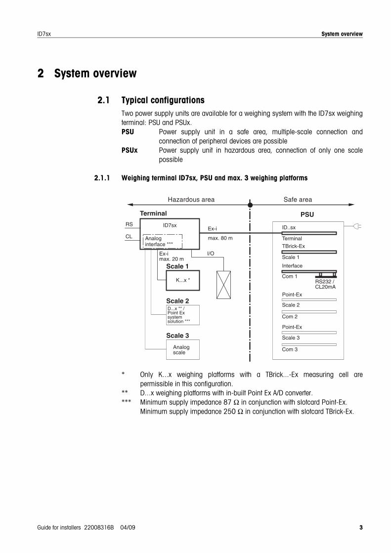
2.1 Typical configurationsTwo power supply units are available for a weighing system with the ID7sx weighingterminal: PSU and PSUx.PSU Power supply unit in a safe area, multiple-scale connection and
connection of peripheral devices are possiblePSUx Power supply unit in hazardous area, connection of only one scale
possible
2.1.1 Weighing terminal ID7sx, PSU and max. 3 weighing platforms
* Only K...x weighing platforms with a TBrick...-Ex measuring cell arepermissible in this configuration.
** D...x weighing platforms with in-built Point Ex A/D converter.*** Minimum supply impedance 87 Ω in conjunction with slotcard Point-Ex.
Minimum supply impedance 250 Ω in conjunction with slotcard TBrick-Ex.
Analogscale
Interface
ID..sx
PSU
Com 1
Terminal
Terminal
Ex-i
Com 2
Scale 2
Com 3
Scale 3
RS232 /CL20mA
max. 80 m
TBrick-Ex
Scale 1
Point-Ex
Point-Ex
Scale 2
Scale 3
Scale 1
Ex-imax. 20 m
K...x *
RS
CL
D...x ** /Point Exsystemsolution ***
ID7sx
Analoginterface ***
I/O
System overview
4 Guide for installers 22008316B 04/09
ID7sx
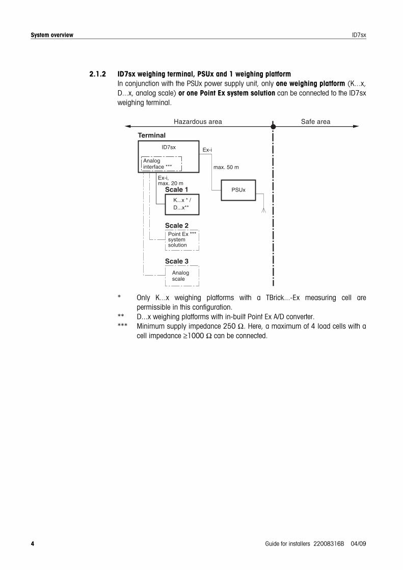
2.1.2 ID7sx weighing terminal, PSUx and 1 weighing platformIn conjunction with the PSUx power supply unit, only one weighing platform (K...x,D...x, analog scale) or one Point Ex system solution can be connected to the ID7sxweighing terminal.
* Only K...x weighing platforms with a TBrick...-Ex measuring cell arepermissible in this configuration.
** D...x weighing platforms with in-built Point Ex A/D converter.*** Minimum supply impedance 250 Ω. Here, a maximum of 4 load cells with a
cell impedance ≥1000 Ω can be connected.

System overview
Guide for installers 22008316B 04/09 5
ID7sx
2.1.3 ID7sx weighing terminal, PSU, max. 2 weighing platforms and barcode scanner
* Only K...x weighing platforms with a TBrick...-Ex measuring cell arepermissible in this configuration.
** D...x weighing platforms with in-built Point Ex A/D converter.*** Slotcard Viper-Ex (SW) as a power supply card for barcode scanners.
2.1.4 D7sx weighing terminal, PSU, connection to Profibus-DP
Ex-i,max. 20 m
Com 1
Terminal
Scale 1
Scale 3
Scale 2
Com 2
Viper-Ex (SW)***
Com 3
Barcode scanner
Hazardous area Safe area
Interface
ID..sx
PSU
ID7sx
RS232 /CL20mA
TBrick-Ex
K...x-T4*
D...x**/SystemsolutionPoint Ex
e.g.ELB SK200(SC20-MTA1)
RS232
CL
Point-Ex
Terminal
Com 1
Terminal
Scale 1
Scale 3
Scale 2
Com 2
Com 3
Ex-i,max. 20 m
K...x-T4*
Hazardous area Safe area
Interface
ID..sx
PSU
ID7sx
RS232
Terminal
ModuleProfibus-DP
PLC withProfibus-DP
interface
24 V DC
Profibus-D
P
TBrick-Ex
System overview
6 Guide for installers 22008316B 04/09
ID7sx
2.2 Description of the components
2.2.1 Approvals
ID7sx weighing terminal Ignition protection type EN II 2G EEx ib IIC T4 –10 °C to +40 °CII 2D IP65 T +55 °C
FM Class I, II, III; Division 1; Group A, B, C, D, E, F, G
Power supply unit PSU/PSUx
See installation instructions for PSU or PSUx
K...x / D...xweighing platforms
See operating/installation instructions of the K...x or D...x weighing platforms.
System solution Point Ex See guide for installers system solution Point Ex.
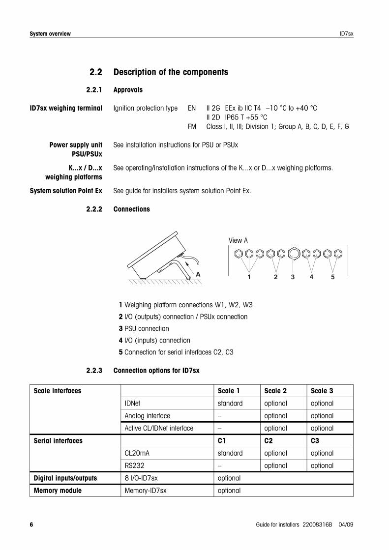
2.2.2 Connections
1 Weighing platform connections W1, W2, W3
2 I/O (outputs) connection / PSUx connection
3 PSU connection
4 I/O (inputs) connection
5 Connection for serial interfaces C2, C3
2.2.3 Connection options for ID7sx
A 1 2 3 4 5
View A
Scale interfaces Scale 1 Scale 2 Scale 3
IDNet standard optional optional
Analog interface – optional optional
Active CL/IDNet interface – optional optional
Serial interfaces C1 C2 C3
CL20mA standard optional optional
RS232 – optional optional
Digital inputs/outputs 8 I/O-ID7sx optional
Memory module Memory-ID7sx optional
Installation
Guide for installers 22008316B 04/09 7
ID7sx
3 Installation
EXPLOSION HAZARDThe explosion-protected weighing system may only be installed according to therespective guide for installers and the accompanying terminal diagram, dependingon the power supply unit.
3.1 Setting up system modules
3.1.1 Setting up ID7sx weighing terminal
Select a suitable installation site.
Bench stand or floor stand mounting
1. Remove stand clip on the ID7sx.
2. Place weighing terminal onto the bench or floor stand and mount with 4 screws.
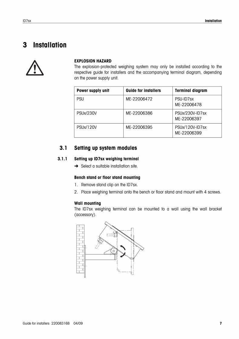
Wall mountingThe ID7sx weighing terminal can be mounted to a wall using the wall bracket(accessory).
Power supply unit Guide for installers Terminal diagram
PSU ME-22006472 PSU-ID7sxME-22006478
PSUx/230V ME-22006386 PSUx/230V-ID7sxME-22006397
PSUx/120V ME-22006395 PSUx/120V-ID7sxME-22006399
Installation
8 Guide for installers 22008316B 04/09
ID7sx
Procedure 1. Drill securing holes and fit plugs in accordance with the drilling template onPage 23.
2. Remove stand clip on the ID7sx.
3. Mount wall stand to weighing terminal with 4 screws.
4. Mount wall stand to the wall with the supplied 3 screws.
Installation in a switch cabinetThe mounting materials and a drilling template are included in the scope of supply.
Discontinue the power supply before beginning installation work.
Producing cut-out onswitch cabinet
1. Tape the drilling template onto the inside of the switch cabinet and mark theholes with a punch.
2. Drill holes with the specified diameter.
3. Saw out the cut-out for the cover exactly with the sabre saw, as otherwiseprotection type IP65/IP66 will no longer be ensured.
4. Remove the drilling template from the switch cabinet again.
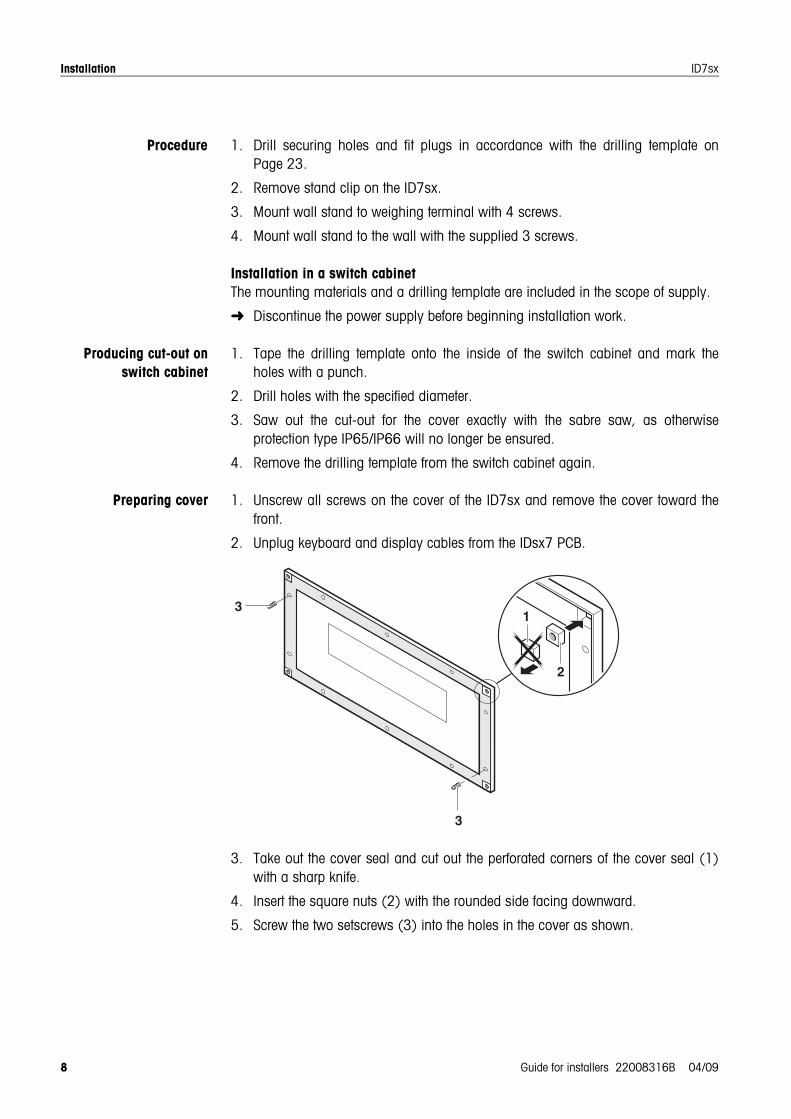
Preparing cover 1. Unscrew all screws on the cover of the ID7sx and remove the cover toward thefront.
2. Unplug keyboard and display cables from the IDsx7 PCB.
3. Take out the cover seal and cut out the perforated corners of the cover seal (1)with a sharp knife.
4. Insert the square nuts (2) with the rounded side facing downward.
5. Screw the two setscrews (3) into the holes in the cover as shown.
1
2
3
3
Installation
Guide for installers 22008316B 04/09 9
ID7sx
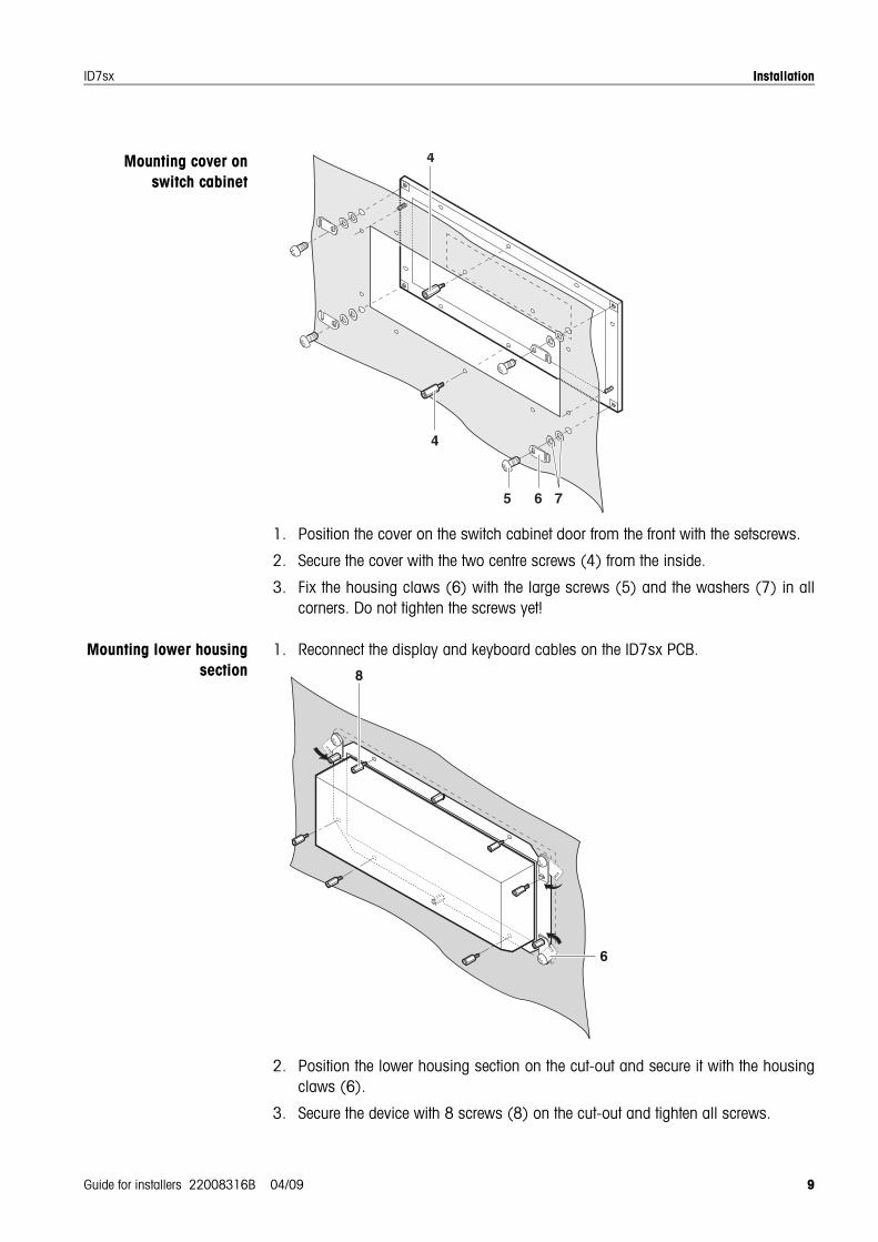
Mounting cover onswitch cabinet
1. Position the cover on the switch cabinet door from the front with the setscrews.
2. Secure the cover with the two centre screws (4) from the inside.
3. Fix the housing claws (6) with the large screws (5) and the washers (7) in allcorners. Do not tighten the screws yet!
Mounting lower housingsection
1. Reconnect the display and keyboard cables on the ID7sx PCB.
2. Position the lower housing section on the cut-out and secure it with the housingclaws (6).
3. Secure the device with 8 screws (8) on the cut-out and tighten all screws.
4
4
5 6 7
8
6
Installation
10 Guide for installers 22008316B 04/09
ID7sx
3.1.2 Setting up power supply unit
Set up the power supply unit in accordance with the respective terminal diagramand the accompanying guide for installers.
3.1.3 Setting up weighing platforms
NoteWhen operating using the PSU power supply unit, a corresponding slotcard must beinstalled for each weighing platform or system solution Point Ex.
Set up weighing platform or analog scale in accordance with the K...x or D...xoperating/installation instructions or guide for installers.
3.2 Connecting devicesConnect the devices in the following order:
1. Weighing platform(s) and/or system solution Point Ex to ID7sx weighingterminal.
2. Interfaces (I/O, CL, Active CL/IDNet or RS232) if present.
3. ID7sx weighing terminal to PSU or PSUx power supply unit.
4. Equipotential bonding, see Section 3.4.
5. Connect power supply, see Section 3.5.
3.2.1 Preparatory workConnection of the devices is generally carried out with the accompanying standardcables. Cables of other lengths can be used instead of the standard cables if they aremade in accordance with Section 4.1. This applies for the connections
• from the weighing platform or system solution Point Ex to the weighing terminal,
• from the weighing terminal to the power supply unit,
• from the interface(s) to the weighing terminal.
3.2.2 General connection procedure
1. Open the device.
2. Insert custom-made cable. To do this
– remove the blind plug– ensure exact course of cable and properly positioned seals– tighten screw gland, using a tubular hexagon box spanner if possible
3. Connect cable in the device according to the terminal diagram.
4. Lay cable in the cable holders on the inside of the housing.
5. Attach plug label.
6. Close device.
Installation
Guide for installers 22008316B 04/09 11
ID7sx
3.2.3 Connection of the digital inputs/outputs at the ID7sx
CAUTIONDesign, calculation and installation of equipment to the digital inputs/outputs issolely the responsibility of the owner.
1. Connect only intrinsically-safe equipment.
2. Check characteristic values for intrinsic safety in accordance with the conformitycertificate of the ID7sx and the equipment to be connected according to theconditions in Section 3.3. Document checking of the characteristic values.
3. Make a cable on the weighing terminal side in accordance with Section 4.1 andon the peripheral side according to the device to be connected. Heed themaximum cable length here.
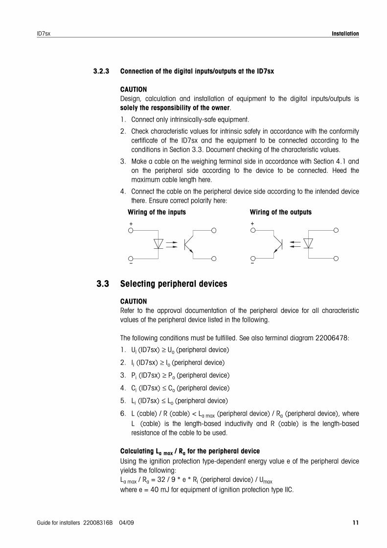
4. Connect the cable on the peripheral device side according to the intended devicethere. Ensure correct polarity here:
3.3 Selecting peripheral devices
CAUTIONRefer to the approval documentation of the peripheral device for all characteristicvalues of the peripheral device listed in the following.
The following conditions must be fulfilled. See also terminal diagram 22006478:
1. Ui (ID7sx) ≥ Uo (peripheral device)
2. Ii (ID7sx) ≥ Io (peripheral device)
3. Pi (ID7sx) ≥ Po (peripheral device)
4. Ci (ID7sx) ≤ Co (peripheral device)
5. Li (ID7sx) ≤ Lo (peripheral device)
6. L (cable) / R (cable) < La max (peripheral device) / Ra (peripheral device), whereL (cable) is the length-based inductivity and R (cable) is the length-basedresistance of the cable to be used.
Calculating La max / Ra for the peripheral deviceUsing the ignition protection type-dependent energy value e of the peripheral deviceyields the following:La max / Ra = 32 / 9 * e * Ri (peripheral device) / Umax
where e = 40 mJ for equipment of ignition protection type IIC.
Wiring of the inputs Wiring of the outputs
Installation
12 Guide for installers 22008316B 04/09
ID7sx
3.4 Equipotential bondingEquipotential bonding must be installed by an electrician authorised by the owner.METTLER TOLEDO Service only has a monitoring and consulting function here.
Connect equipotential bonding (PA) of all devices (power supply unit, weighingterminal and weighing platform) in accordance with the terminal diagram andthe country-specific regulations and standards. In the process it must be ensuredthat– all device housings are connected to the same potential via the PA terminals– no circulating current flows via the cable shielding for intrinsically-safe circuits– the neutral point for equipotential bonding is as close to the scale as possible
3.5 Connecting power supply
EXPLOSION HAZARDThe mains connection of the power supply unit must be made by a professionalelectrician authorised by the owner and in accordance with the respective terminaldiagram and the accompanying installation instructions and the country-specificregulations.

Optional work
Guide for installers 22008316B 04/09 13
ID7sx
4 Optional work
4.1 Making connection cablesCustomer-specific weighing platform cables for intrinsically-safe circuits must befabricated as follows:
1. Cut cable to length and strip cable ends according to dimension A/B.
2. Shorten shielding on both sides to 10 mm.
3. Strip wire ends.
4. Crimp wire end ferrules onto wire ends with a crimping tool.
5. Push second rear section of earthing cable gland onto cable.
6. Push sleeve over wires and shield. Fold over cable shield.
7. Push on front section of cable gland and screw onto rear section.
Observe the following when connecting the weighing platform
1. When opening the terminal box of the weighing platform, remove the load plate ifnecessary.
2. For weighing platforms of type KC, attach the cable to the base frame with acable tie in such a way that it does not contact the moving lever system.
3. For K...x weighing platforms, pull off the tear-away screw at the terminal box ofthe weighing platform after connection of the weighing platform to the weighingterminal for safety purposes.
4. Replace load plate if necessary.
Cable Dimension A (ID7sx) Dimension B Max. length
ID7sx – PSU 9x2x0.5 mm2 215 mm1 215 mm1 80 m1
ID7sx – weighing platform / system solution Point Ex
3x2x0.75 mm2 215 mm1 80 mm1 20 m1
A B
Earthing cable screw gland
Cable shield
Push sleeve over wires and shield
According to country-specific regulations for intrinsically-safe circuits
Wire end ferruleswith plastic collar,crimp connection
Optional work
14 Guide for installers 22008316B 04/09
ID7sx
4.2 Installing additional scale interface or Active CL/IDNet moduleUp to two additional scale interfaces (IDNet or analog) or Active CL/IDNet modulescan be installed in the ID7sx weighing terminal if not already installed at the factory.The ID7sx, for example, can be connected to another ID7sx as a second display withthe Active CL/IDNet-ID7sx module in the hazardous area.
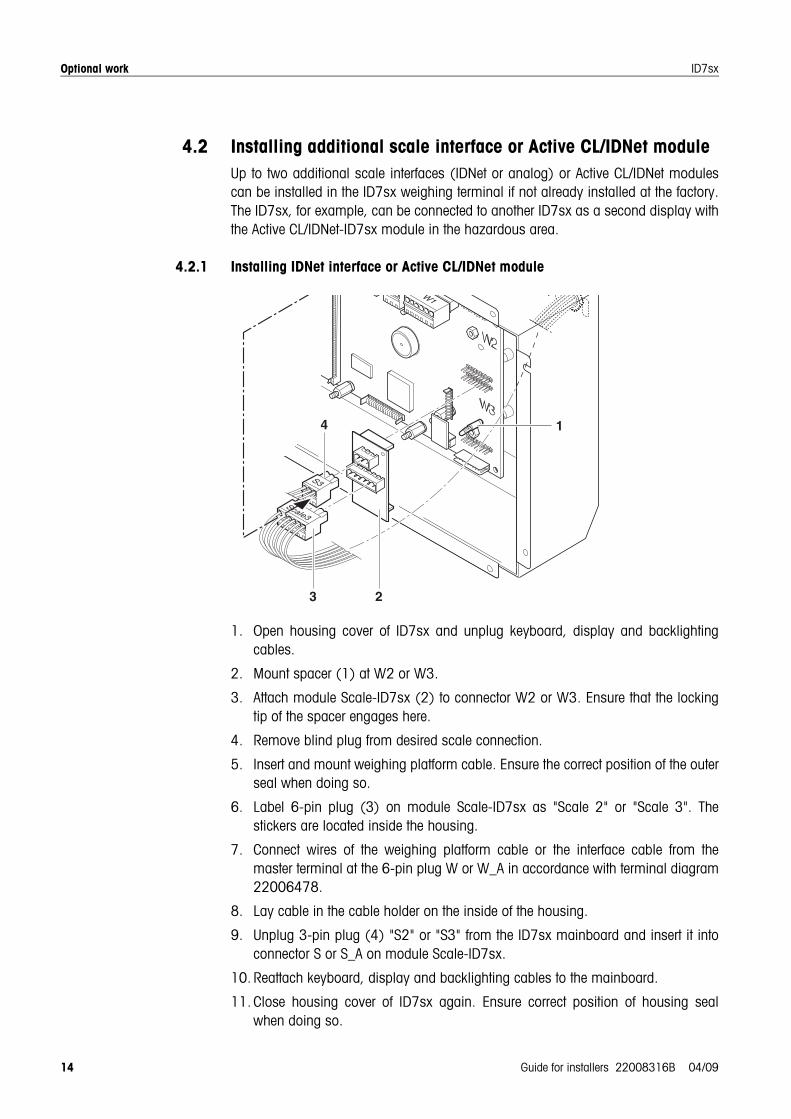
4.2.1 Installing IDNet interface or Active CL/IDNet module
1. Open housing cover of ID7sx and unplug keyboard, display and backlightingcables.
2. Mount spacer (1) at W2 or W3.
3. Attach module Scale-ID7sx (2) to connector W2 or W3. Ensure that the lockingtip of the spacer engages here.
4. Remove blind plug from desired scale connection.
5. Insert and mount weighing platform cable. Ensure the correct position of the outerseal when doing so.
6. Label 6-pin plug (3) on module Scale-ID7sx as "Scale 2" or "Scale 3". Thestickers are located inside the housing.
7. Connect wires of the weighing platform cable or the interface cable from themaster terminal at the 6-pin plug W or W_A in accordance with terminal diagram22006478.
8. Lay cable in the cable holder on the inside of the housing.
9. Unplug 3-pin plug (4) "S2" or "S3" from the ID7sx mainboard and insert it intoconnector S or S_A on module Scale-ID7sx.
10. Reattach keyboard, display and backlighting cables to the mainboard.
11. Close housing cover of ID7sx again. Ensure correct position of housing sealwhen doing so.
W1
Scale3
S3
23
4 1
Optional work
Guide for installers 22008316B 04/09 15
ID7sx
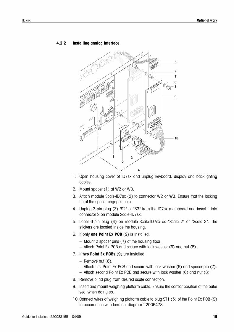
4.2.2 Installing analog interface
1. Open housing cover of ID7sx and unplug keyboard, display and backlightingcables.
2. Mount spacer (1) at W2 or W3.
3. Attach module Scale-ID7sx (2) to connector W2 or W3. Ensure that the lockingtip of the spacer engages here.
4. Unplug 3-pin plug (3) "S2" or "S3" from the ID7sx mainboard and insert it intoconnector S on module Scale-ID7sx.
5. Label 6-pin plug (4) on module Scale-ID7sx as "Scale 2" or "Scale 3". Thestickers are located inside the housing.
6. If only one Point Ex PCB (9) is installed:
– Mount 2 spacer pins (7) at the housing floor.– Attach Point Ex PCB and secure with lock washer (6) and nut (8).
7. If two Point Ex PCBs (9) are installed:
– Remove nut (8).– Attach first Point Ex PCB and secure with lock washer (6) and spacer pin (7).– Attach second Point Ex PCB and secure with lock washer (6) and nut (8).
8. Remove blind plug from desired scale connection.
9. Insert and mount weighing platform cable. Ensure the correct position of the outerseal when doing so.
10. Connect wires of weighing platform cable to plug ST1 (5) of the Point Ex PCB (9)in accordance with terminal diagram 22006478.
!
!"
!
#
$!
#
#
Optional work
16 Guide for installers 22008316B 04/09
ID7sx
11. Lay cable in the cable holder on the inside of the housing.
12. Connect 6-lead connection cable (10) between the 6-pin plug of the Scale-ID7sxmodule and the ST2 plug at the Point Ex PCB.
13. Reattach keyboard, display and backlighting cables to the mainboard.
14. Close housing cover of ID7sx again. Ensure correct position of housing sealwhen doing so.
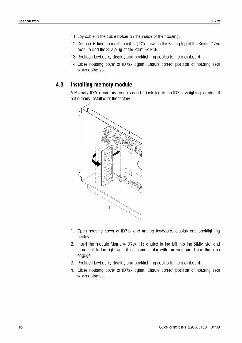
4.3 Installing memory moduleA Memory-ID7sx memory module can be installed in the ID7sx weighing terminal ifnot already installed at the factory.
1. Open housing cover of ID7sx and unplug keyboard, display and backlightingcables.
2. Insert the module Memory-ID7sx (1) angled to the left into the SIMM slot andthen tilt it to the right until it is perpendicular with the mainboard and the clipsengage.
3. Reattach keyboard, display and backlighting cables to the mainboard.
4. Close housing cover of ID7sx again. Ensure correct position of housing sealwhen doing so.
C1
T1S3
S2S1
S3
1
Optional work
Guide for installers 22008316B 04/09 17
ID7sx
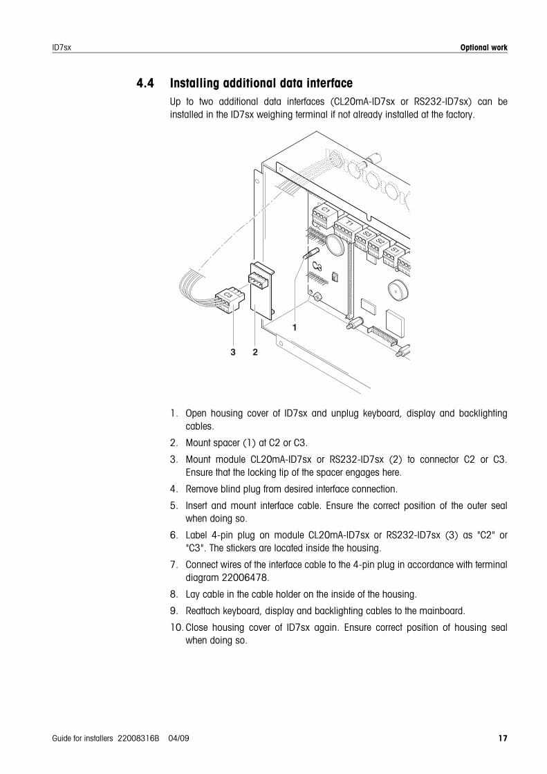
4.4 Installing additional data interfaceUp to two additional data interfaces (CL20mA-ID7sx or RS232-ID7sx) can beinstalled in the ID7sx weighing terminal if not already installed at the factory.
1. Open housing cover of ID7sx and unplug keyboard, display and backlightingcables.
2. Mount spacer (1) at C2 or C3.
3. Mount module CL20mA-ID7sx or RS232-ID7sx (2) to connector C2 or C3.Ensure that the locking tip of the spacer engages here.
4. Remove blind plug from desired interface connection.
5. Insert and mount interface cable. Ensure the correct position of the outer sealwhen doing so.
6. Label 4-pin plug on module CL20mA-ID7sx or RS232-ID7sx (3) as "C2" or"C3". The stickers are located inside the housing.
7. Connect wires of the interface cable to the 4-pin plug in accordance with terminaldiagram 22006478.
8. Lay cable in the cable holder on the inside of the housing.
9. Reattach keyboard, display and backlighting cables to the mainboard.
10. Close housing cover of ID7sx again. Ensure correct position of housing sealwhen doing so.
C3
C1
T1S3
S2S1
W
S3
3 2
1
Optional work
18 Guide for installers 22008316B 04/09
ID7sx
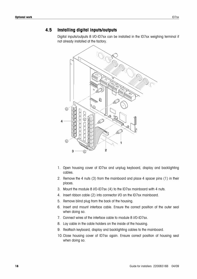
4.5 Installing digital inputs/outputsDigital inputs/outputs 8 I/O-ID7sx can be installed in the ID7sx weighing terminal ifnot already installed at the factory.
1. Open housing cover of ID7sx and unplug keyboard, display and backlightingcables.
2. Remove the 4 nuts (3) from the mainboard and place 4 spacer pins (1) in theirplaces.
3. Mount the module 8 I/O-ID7sx (4) to the ID7sx mainboard with 4 nuts.
4. Insert ribbon cable (2) into connector I/O on the ID7sx mainboard.
5. Remove blind plug from the back of the housing.
6. Insert and mount interface cable. Ensure the correct position of the outer sealwhen doing so.
7. Connect wires of the interface cable to module 8 I/O-ID7sx.
8. Lay cable in the cable holders on the inside of the housing.
9. Reattach keyboard, display and backlighting cables to the mainboard.
10. Close housing cover of ID7sx again. Ensure correct position of housing sealwhen doing so.
C1
T1S3
S2S1
W1
S3
4
3 2
1

Optional work
Guide for installers 22008316B 04/09 19
ID7sx
4.6 Connecting barcode scanner A barcode scanner, e.g. ELB SK200 (SC20-MTA1), can be connected to the ID7sxweighing terminal via an intrinsically safe RS232 data interface.The barcode kit for ID7sx consists of the following components:
• Barcode scanner ELB SK200 (SC20-MTA1)
• RS232-ID7sx module
• Viper-Ex slotcard (SW)
• Screw gland
Mounting
1. Install Viper-Ex (SW) slotcard in the PSU. See PSU installation instructions.
2. Install RS232-ID7sx module in the ID7sx weighing terminal as COM2 or COM3.See Section 4.4.
3. Pull in the barcode scanner cable and mount it with the screw gland.
4. Connect wires of the barcode scanner cable at plug C2 or C3 in accordance withterminal diagram 22006478.CautionThe yellow wire insulated with a heat-shrink sleeve may not be connected in thehazardous area!
Note
• The yellow wire of the barcode scanner cable is insulated with a 1.5 cm heat-shrink sleeve at the factory.
• The green, brown and white wire of the barcode scanner cable is stripped 3 cm atthe factory and provided with wire-end ferrules.
yellow
green
brown
white
wire end ferules
Heat-shrink sleeve 1.5 cm
3 cm
R./4
R./3
R./2
R./1

Optional work
20 Guide for installers 22008316B 04/09
ID7sx
4.7 Attaching Profibus-DP moduleThe ID7sx can be connected to a Profibus network with the Profibus-DP module.The Profibus-DP module is a top-hat rail module for installation in the controlcabinet. It requires an external power supply of 24 V DC +/- 20%, 100 mA.
ConditionA slotcard interface with the RS232-PSU module must be installed and connected upin the PSU for a data interface CL20mA-ID7sx of the ID7sx. See Section 4.4 or thePSU installation instructions.
1. Insert the Profibus-DP module at the relevant interface connection of the PSU.
2. Connect the Profibus-DP module to the 24 V power supply.
3. Integrate the Profibus-DP module into the Profibus network.
4. In master mode of the ID7sx, select the PROFIBUS DP operating mode for therelevant interface and set parameters. See ID7sx weighing terminal operatinginstructions.
5. De-energise the Profibus-DP module after setting all parameters.
6. Connect the Profibus-DP module to the power supply again. The parametersettings made are now active and the ID7sx is integrated into the Profibus-DPnetwork.
Dimensional drawings
Guide for installers 22008316B 04/09 21
ID7sx
5 Dimensional drawings
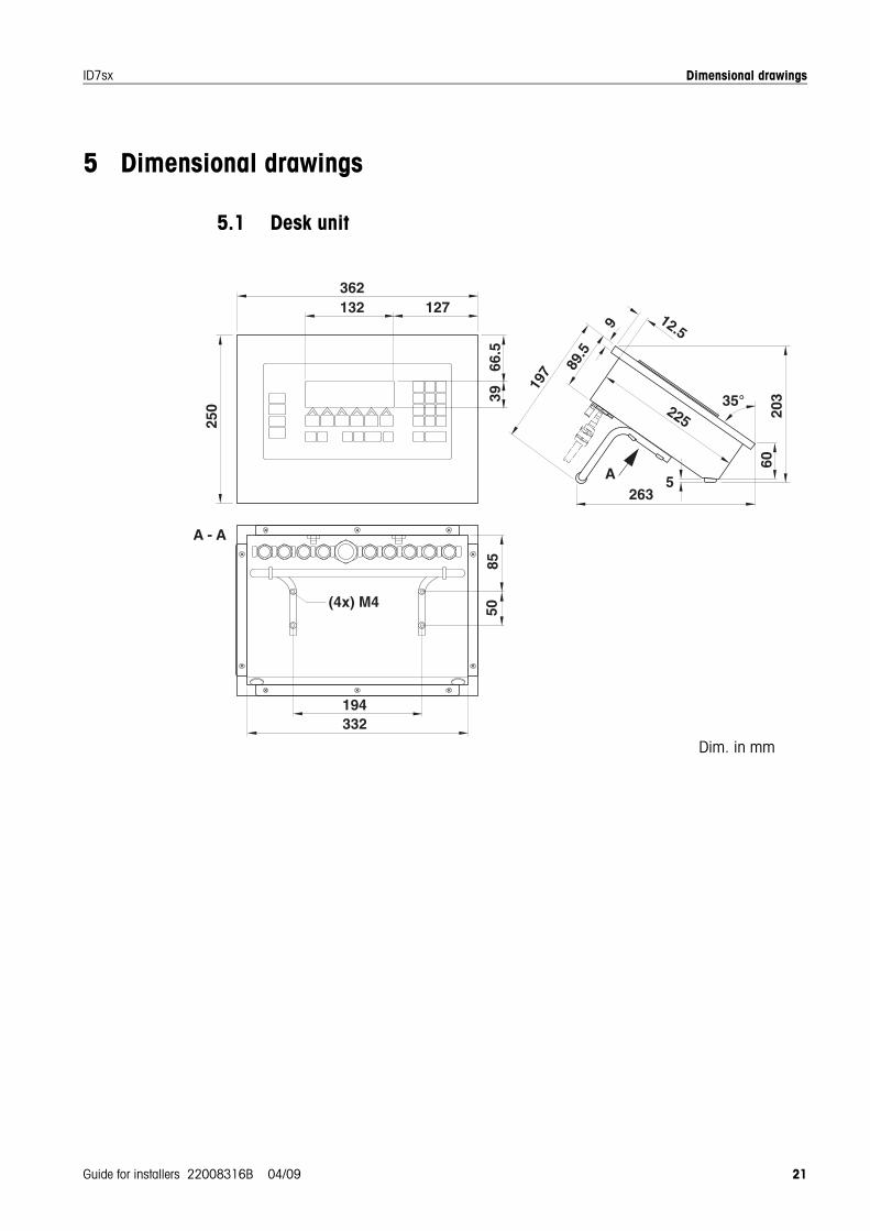
5.1 Desk unit
5
89.5
9 12.5
60
263
197
132 127362
66.5
A
225
194332
8550
35°
20339
250
(4x) M4
A - A
Dim. in mm
Dimensional drawings
22 Guide for installers 22008316B 04/09
ID7sx
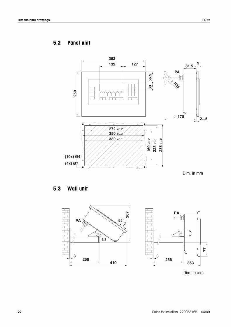
5.2 Panel unit
5.3 Wall unit
Dim. in mm
77
353256
PA
3
207
410256
PA 55°
3
Dim. in mm
Dimensional drawings
Guide for installers 22008316B 04/09 23
ID7sx
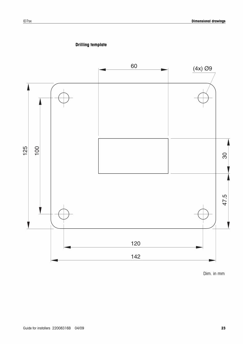
Drilling template
%
!
!&
!
!
#&
'&()*
Dim. in mm

22008316B
Subject to technical changes © Mettler-Toledo (Albstadt) GmbH 04/09 Printed in Germany 22008316B
Mettler-Toledo (Albstadt) GmbHD-72458 AlbstadtTel. ++49-7431-14 0, Fax ++49-7431-14 232Internet: http://www.mt.com