non-sce antennas placed on sce poles antennas placed on sce poles page 1 1.0 introduction the...
TRANSCRIPT

Non-SCE Antennas Placed on Wood Distribution Poles
SOUTHERN CALIFORNIA EDISON (SCE)
Non-SCE Antennas Placed on SCE Poles
External Manual
December 2016

Copyright © 2016 Southern California Edison. All rights reserved.
No part of this document may be reproduced, stored in a retrieval system, or transmitted, in any form or by any means, without the prior written permission of Southern California Edison.
SOUTHERN CALIFORNIA EDISON
TRANSMISSION AND DISTRIBUTION
STANDARDS AND PUBLICATIONS
1 INNOVATION WAY, POMONA, CALIFORNIA 91768-2560PAX: 61646 • VOICE: (909) 274-1646 • EMAIL: [email protected]

Non-SCE Antennas Placed on Wood Distribution Poles
Page i
Table of Contents
1.0 Introduction
2.0 Application Process
3.0 Antenna Installation
4.0 Inspection – Maintenance
5.0 Design Specifications – Exhibit “A”
6.0 Attachments
Attachment 1 : Typical High Voltage Distribution Pole with Non-SCE Antenna . . . . . . . . . . . . . . . . . . . . . . . .12
Attachment 2 : Typical Low Voltage Distribution Pole with Non-SCE Antenna. . . . . . . . . . . . . . . . . . . . . . . . .13
Attachment 3 : Typical Guy Pole with Non-SCE Antenna . . . . . . . . . . . . . . . . . . . . . . . . . . . . . . . . . . . . . . . . .14
Attachment 4 : Typical High Voltage Distribution Pole with Non-SCE Cable/Strand Mounted Omni Antenna .15
Attachment 5 : Non-SCE Directional Antenna Between Transmission and Distribution Lines . . . . . . . . . . . . .16
Attachment 6: Emergency RF/Power Shut-Off Switch . . . . . . . . . . . . . . . . . . . . . . . . . . . . . . . . . . . . . . . . . . .17
Attachment 7: Omni-Directional Antenna and Directional Antenna . . . . . . . . . . . . . . . . . . . . . . . . . . . . . . . . .17
Attachment 8: Example of Non-SCE Cable/Strand Mounted Omni Antenna Attached to Communication Cables . . . . . . . . . . . . . . . . . . . . . . . . . . . . . . . . . . . . . . . . . . . . . . . . . . . . . . . . . . . . . . . . . . .18
7.0 Contact Information

This page intentionally left blank.

Non-SCE Antennas Placed on SCE Poles
Page 1
1.0 Introduction
The following is a guide to be used by any entity seeking to purchase or lease space from SCE for the purpose of installing an antenna(s) on distribution poles supporting energized conductors (up to 33 kV). New or additional attachments to SCE poles (either solely or jointly owned) by a Foreign Utility such as an Owner/Member of the Southern California Joint Pole Committee (SCJPC), the Tenant of a Foreign Utility, an SCE Tenant, or any other entity, shall not be made except when permission is granted by an authorized SCE representative.
1.1 The terms “antenna(s)” and “antenna site” mean one device, or a combination of devices, including ancillary equipment, that does not emit and/or receive Radio Frequency (RF) energy in excess of the Federal Communications Commission (FCC) General Population/Uncontrolled Exposure limits, as set forth in 47 Code of the Federal Regulation (C.F.R.) and described in Office of Engineering and Technology (OET) Bulletin 65.
1.2 The term “attachment(s)” is to be used for all antenna(s) that will be located within the climbing space and working space as defined in California’s General Order 95, Rule 94. Should an SCE standard and a GO-95 rule conflict, the more stringent of the two requirements shall be applied.
Note(s): Microwave antenna(s) are prohibited on all distribution and sub-transmission poles.
2.0 Application Process
2.1 Southern California Joint Pole Organization (JPO) processes all Joint Pole Authorizations (JPA) Pole License Agreements (PLA), Pole Use Agreements for Antenna Attachments (PUA), and Pole License Agreements for Commercial Mobile Radio Service (PLA-CMRS) along with Request for Access (RFA) or Request for Access-Commercial Mobile Radio Service (RFA-CMRS) applications.
Contact: Southern California Joint Pole Organization14005 South Benson Ave.Chino, California 91710-7026JPAs: [email protected]: [email protected]

Non-SCE Antennas Placed on SCE Poles
Page 2
A. Members of the SCJPC wishing to install antenna(s) below SCE facilities (e.g.lines, equipment, guys) will abide by the requirements established in the SCJPC Agreement and Routine Handbook and will submit the following:
1. A completed JPA, J.P. Form 2-1.
2. Two copies of Installation Management Services (IMS) Information Sheet.
3. Two copies of power service option letter signed by appropriate permitting agency.
4. Two copies of engineered site plan and construction drawings, approved by appropriate permitting agency.
5. Two copies of pole loading calculations, including all SCE attachments.
6. Two copies of Antenna Information Form (AIF).
B. Non-members of the SCJPC wishing to install antenna(s) below SCE facilities (e.g. lines, equipment, guys) in space owned by SCE will abide by the requirements established in a fully executed “Pole Use Agreement for Antenna Attachments” and “Request for Access” (RFA) application and will submit the following:
1. Two copies of a completed RFA application.
2. Check for processing fee ($80.00 per RFA). Make checks payable to Southern California Edison
3. One copy of Customer Information Form.
4. Two copies of Certificate of Insurance.
5. Make Ready or Technical data sheet(s)
6. Proposed construction map(s)
7. Two copies of IMS Information Sheet.
8. Two copies of signed power service option letter from permitting agency.
9. Two copies of engineered site plan and construction drawings, approved by appropriate permitting agency.
10. Two copies of pole loading calculations, including all SCE attachments.
NOTE ONLY ONE POLE AGREEMENT IS REQUIRED FOR EACH APPLICANT
NOTE EACH ANTENNA ATTACHMENT REQUIRES ITS OWN RFA APPLICATION

Non-SCE Antennas Placed on SCE Poles
Page 3
C. CMRS provider entities wishing to install antenna(s) located above, below, or between SCE facilities (e.g lines, equipment, guys) in space owned by SCE will abide by the requirements established in a fully executed “Pole Licencse Agreement for Commercial Mobile Radio Service (PLA-CMRS)” and a “Request for Access - Commercial Mobile Radio Service” (RFA-CMRS) application. Prior to SCE distributing the Pole License Agreement for Commerical Mobile Radio Service (PLA-CMRS) to an applicant, there are two (2) pre-requisites providers must complete:
1. CMRS provider must submit antenna equipment to IMS for pre-vetting and catalog inven-tory process.
2. CMRS provider must provide a declaration, signed and dated by a company representa-tive, stating they are a bona-fide commercial mobile radio service provider, recognized by the CPUC.
a. Wireless Identification Registration (WIR)
b. Certificate of Public Convenience and Necessity (CPCN)
Note: Attach a copy of WIR or CPCN, along with signed declaration. Email with subject line formatted as: PLA-CMRS REQUEST-your company name. Send to SCE's Joint Pole Organization's email: [email protected] . Documents are reviewed by SCE representative who will contact originator with detailed instructions and requirements to initiate a Pole License Agreement For Commercial Mobile Radio Service (PLA-CMRS). After PLA-CMRS is fully executed then a Request For Access-Commercial Mobile Radio Service will be sent to the company representative within seven (7) calendar days.
D. The following steps outline requirements for a Commercial Mobile Radio Service provider completing an RFA-CMRS application:
1. Two copies of a completed RFA-CMRS application.
2. Check for processing fee (amount reflected in RFA-CMRS package). Make checks payable to: Southern California Edison
3. One Customer Information Form.
4. Two copies of Certificate of Insurance.
5. Two copies of IMS Information Sheet.
6. Two copies of signed power service option letter from permitting agency.
7. Two copies of engineered site plan and construction drawings, approved by appropriate permitting agency.
8. Two copies of pole loading calculations, including all SCE attachments.
NOTE EACH ANTENNA ATTACHMENT REQUIRES ITS OWN APPLICATION.

Non-SCE Antennas Placed on SCE Poles
Page 4
2.2 IMS Manages all non-SCE antenna attachments on distribution poles and sub-transmission poles.
A. IMS receives application from JPO (either JPA or RFA), and confirms application with Applicant.
B. IMS prepares the Preliminary Design Work Order Package. (Submittal Package)
C. IMS creates and sends Engineering Advance invoice (if applicable) to Applicant.
D. IMS forwards completed Submittal Package to Design Resource (DR).
1. DR confirms Submittal Package with Applicant.
2. DR arranges for a pre-design field meet with IMS and Applicant to determine method of service and if attachment location is accessible without entering or working in the Electrical Zone.
3. DR, IMS, and Applicant meet in field to determine if preliminary design is constructible.
Note:
• The Electrical Zone, on poles supporting energized conductors 120 Volts to 33,000 Volts, is defined as the pole space, measured vertically, starting 3 ft. below the lowest conductor level up to 3 ft. above the uppermost conductor level.
• The licensee (or their contractor) is prohibited from accessing the electrical zone.
• Only SCE, or authorized contractors working for SCE, and only when contracted directly by SCEm will have access to the electrical zone
• Only SCE or its authorized contractors will perform all installation work for equipment attached to the pole in and above the electrical zone.
• Licensee has the option of using SCE authorized contractor (under separate contract) or their own for installing antennas outside the electrical zone.
• Licensee is granted access only to the leased space, provided it can be accessed without encroachment into the electrical zone and they maintain all G.O. 95 minimum clearances or clearances as required by SCE.

Non-SCE Antennas Placed on SCE Poles
Page 5
2.3 IMS receives approved Submittal Package and submits invoice to Licensee.
2.4 Location Selection
A. Choose the shortest pole possible to that will allow operation of the antenna while minimizing visual impact.
B. When possible, select a pole supporting only secondary voltage and communications conductors.
C. When a pole that supports primary voltage (2.4 kV to 33 kV) will be selected, consider poles carrying small diameter wires built on a single cross-arm in tangent configuration (i.e. no dead-ends, guy wires, or corner poles).
D. The pole should not support other SCE equipment, such as fused cutouts, switches, capacitors, transformers, etc.
E. Ease of access to the proposed antenna location is highly desirable to allow for the maintenance and repair of equipment. Locations along streets or alleys are best. Back yards should be avoided when possible, as well as locations adjacent to fences, landscaping, or other obstructions.
3.0 Antenna Installation
3.1 IMS to coordinate installation of attachment and schedule the work.
3.2 IMS notifies Licensee of scheduled installation date.
A. If Licensee is performing antenna installation outside the Electrical Zone, then Licensee shall give SCE 30-days written notice and a call 48 hours after approval before antenna is installed.
B. SCE's crews or approved contract crew to work with Licensee's contractors for Passive Intermodulation Testing (PIM) for antennas or equivalent.

Non-SCE Antennas Placed on SCE Poles
Page 6
4.0 Inspection – Maintenance
Joint Owners and Licensees are responsible for inspecting and maintaining their antennas and associated facilities.
4.1 SCE reserves the right to inspect non-SCE antenna installations and notify the Owner/Licensee at any time of unsafe work conditions and/or construction that is not compliant with SCE standards or GO-95 Requirements.
4.2 Entities failing to correct unsafe conditions in a timely manner may be reported to the California Public Utilities Commission Protection and Safety Division, and/or billed for the necessary action undertaken by SCE.
4.3 Owners/Licensees shall perform all routine maintenance outside of the Electrical Zone and shall not cause any interruption of SCE's utility or other services. SCE's crews or SCE's approved Contract crew will perform all maintenance where access is not assessable without going in or through the Electrical Zone. Written notification by Licensee will be given no less than 30 days of when SCE is requested to perform maintenance.

Non-SCE Antennas Placed on SCE Poles
Page 7
5.0 Design Specifications – Exhibit “A”
5.1 General Information
A. This standard applies to non-SCE antennas affixed to poles supporting SCE lines, streetlights, secondary risers, and guys.
B. This is a design standard and is not intended to endorse or assure the installation of antennas on SCE poles.
C. This standard, including the Attachments and Notes, supplement the minimum requirements established in GO-95, including Rule 94 and all other applicable rules. Should this manual and a GO-95 rule conflict, the more stringent of the two requirements shall be applied.
5.2 Support Elements
A. Cables, messengers, ground bond wires, and incidental wiring associated with antennas shall meet the requirements for class C circuits as specified in GO-95, except as modified by this standard.
B. Incidental wiring and miscellaneous equipment associated with antennas shall be installed in a workman-like fashion so as to not interfere with workers ascending or descending the pole, or nearby communication and/or SCE facilities.
C. Hardware (e.g. brackets, cross-arms, braces) associated with Antennas affixed above SCE facilities shall (at a minimum) meet the material strength requirements and safety factors for Grade “A” construction as specified in Section IV of GO-95.
1. Cross-arms supporting antennas above 2.4- 33 kV lines are prohibited.
2. Cross-arms supporting antennas above 120-480 V lines and guys shall extend no more than 5 ft. horizontally from the centerline of the support pole.
• The maximum allowable cross-arm length is 10 feet.
D. Hardware associated with antenna affixed below distribution facilities shall (at a minimum) meet the material strength requirements and safety factors for Grade “C” construction as specified in Section IV of GO-95.
E. Pole-top extensions meeting the requirements of DOH PO 150 may be utilized to support antennas above 120-480 V lines and atop Distribution guy poles.
1. Where a pole-top extension is intended for use, a soil strength calculation for the support pole must be submitted with other required pole load calculations.
NOTE HARDWARE ASSOCIATED WITH POLE-MOUNTED ANTENNAS SHALL BE REVIEWED AND APPROVED BY SCE PRIOR TO CONSTRUCTION.

Non-SCE Antennas Placed on SCE Poles
Page 8
F. Pull boxes, hand-holes, and other subsurface enclosures shall be situated so as to not interfere with down guys, guy anchors, vehicle and pedestrian traffic.
G. Pedestals and above ground equipment shall be situated so as to not interfere with down guys, guy anchors, vehicle and pedestrian traffic.
5.3 Clearances
A. Attachments 1, 2, 3, 4, and 5 specify the required minimum vertical, horizontal, and/or radial clearances.
B. Antennas attach either above or below lines or guys shall maintain clearances from unattached electrical and communication lines in accordance with GO-95, Rule 38, Table 2, Case 3, and Columns A-K.
1. Pole-top antennas above 33 kV distribution lines are addressed by this standard.
2. Pole-top antennas above 33 kV transmission lines are prohibited.
C. Antennas affixed below the lines shall not be installed directly below pole mounted streetlight fixtures nor interfere with the intended illumination pattern.
D. Approved antenna equipment (e.g. light wave converters, amplifiers, grounding devices, batteries) affixed to the support pole shall meet the following requirements:
1. Vertical clearances above the ground line (lowest part) shall be no less than 8 ft.
2. Vertical clearances above the ground line (upper most part) shall be no more than 16 ft.
3. Dimensions of equipment (separate or combined) shall be no more than 96" (L) X 30" (W) X 18" (H).
4. Weight of equipment: No maximum is prescribed, however, vertical loading factors must be calculated and the support pole appropriately sized.
5. Equipment measuring 24" (L) X 24" (W) X 12" (H) or larger, (separately or combined) shall be installed with at least 6" of horizontal separation, measured from the surface of the pole to the nearest part.
5.4 Marking
A. Antenna owner/operators shall provide, and update as necessary, information regarding compliance with the Federal Communication Commission’s Maximum Permissible Exposure (MPE) limits as set forth in Title 47 of the Code of Federal Regulations (CFR) for each antenna site.
B. Antenna owner/operators shall install signs or decals made of weather, corrosion, and Ultraviolet (UV) resistant materials. At a minimum, each sign or decal shall indicate the antenna owner/operator’s name, emergency 24-hour contact number, unique identifier for that antenna site, and SCE equipment catalog number (for pole top installations)

Non-SCE Antennas Placed on SCE Poles
Page 9
C. Affix required signs/decals at two locations on the support structure so they are clearly visible:
1. Install 3 – 4 feet below the antenna (measured from the top of the sign).
2. Install 8 – 10 feet above the ground (measured from the bottom of the sign).
D. When modifying an existing antenna site that requires the replacement or modification of existing markings the antenna owner/operator shall:
1. Notify SCE and all other pole occupants in writing and place new signs/decals that include the information listed above in 5.4 (B) and as listed below:
i. The applicable FCC exposure category (General Population/Uncontrolled or Occupa-tion)
ii. FCC’s recommended minimum approach distance
5.5 Climbing Space
A. Where antennas are installed above lines or guys, climbing space shall be established and maintained in accordance with GO-95, Rule 54.7-A from the ground line to the bottom of the hardware.
B. Where antennas are installed below distribution lines or guys, climbing space shall be established and maintained in accordance with GO-95, Rule 84.7-A from the ground line to within 6 feet of the nearest line or guy.
C. Directional antennas shall be installed and oriented in a manner that limits RF energy within the climbing space.
5.6 Cable Risers and Grounds
A. Where antennas are installed above lines and guys atop wood or other nonmetallic poles, associated cable risers and vertical grounds shall be:
1. Adequately supported
2. Encased in Schedule 40 PVC conduit
3. Installed outside the climbing space and
4. Meet the requirements of GO-95 Rule 54.6-D 1, 2, 3 and 5.
B. On wood poles, where one riser is present, one additional cable riser may be affixed directly to the pole, provided the climbing space is not impaired.
1. Appropriately sized galvanized pipe straps (with no less than three straps per each 10 feet length of conduit) and size 16D nails or equivalent lags shall be utilized.
C. On wood poles where two or more risers are present, any additional risers shall be installed with uni-strut or power-strut riser supports in accordance with DUG CR 110.2.

Non-SCE Antennas Placed on SCE Poles
Page 10
D. On Light Weight Steel poles where antennas are installed, uni-strut or power strut supports shall be utilized in accordance with DUG CR 141.
E. Cables emanating from a pole top antenna riser or transiting from a vertical run that extends to an adjacent pole or building shall be:
1. Bonded to the support pole’s existing communication cables and messengers
2. Effectively grounded in accordance with GO-95 Rule 83.4 and
3. Where a guard arm is present, the bottom of the riser shall extend at least one foot below the guard arm.
F. Ground wires, connectors, and associated grounding equipment installed on nonmetallic poles shall be installed outside the climbing space.
1. Ground wires shall be covered with Schedule 40 PVC conduit or its equivalent wood or PVC molding.
5.7 Stepping
A. On wood poles where risers (of any kind) are present, pole steps shall be installed or rearranged (if pre-existing) to frame the climbing space and continue to a point approximately six feet below the lowest 120-480 V line.
1. For all poles, the first step shall be installed not less than 9 feet above the ground line or any easily climbable foreign structure from which one could reach or step with a maximum vertical separation of 3 feet on the same side of the pole.
5.8 Cable / Messenger Mounted
A. Cable/Messenger mounted antennas shall be installed with at least:
1. Six (6) feet of horizontal clearance (measured from the nearest part of the antennato the surface of the pole).
2. Four (4) feet of vertical clearance below 120 – 480 V lines.
3. Ten (10) feet of vertical clearance below 2.4 – 33 kV lines (where no 120 – 480 V lines are present).
4. Six (6) feet of horizontal clearance from self-supporting streetlights.
B. The maximum length of a Cable/Messenger mounted antenna is 3 feet.
C. Cable/Messenger mounted antennas shall not be installed below pole mounted streetlight fixtures, nor interfere with intended illumination pattern.

Non-SCE Antennas Placed on SCE Poles
Page 11
5.9 Emergency RF / Power Shut-Off Device
A. Antennas affixed to poles supporting lines and/or guys shall be installed with a device that disconnects all RF energy.
1. This device maybe affixed to the support pole, above ground communication equipment, or contained in a subsurface enclosure, but must be located no more than 20 feet from the pole supporting the antenna within line of sight.
2. Devices shall be permanently marked with a weather and UV resistant sign or decal that reads: SCE RF/Power Shut-Off Switch.

Non-SCE Antennas Placed on SCE Poles
Page 12
6.0 Attachments
Attachment 1: Typical High Voltage Distribution Pole with Non-SCE Antenna
Note(s): 1. Antenna markings shall be affixed so as to be clearly visible, at two locations on the support structure. 3-4 feet below the
antenna (measured from the top of the sign), and 8-10 feet above the ground (measured from the bottom of the sign).2. On wood poles, where two or more risers are present, any additional riser shall be installed with unistrut or power-strut
supports in accordance with DUG CR 110.2.3. Antennas atop HV distribution poles - no specified horizontal clearance between the pole and antenna.4. The preferred location of RF/Power Shut-Off Switch is the customer’s pedestal; however, at SCE’s discretion the device
may be affixed on the antenna pole (for non-metered cellular service equipment details, see AP 800).5. Clearance dimensions shown are the required minimum vertical, horizontal, and/or radial clearances.
See Note 3and Figure AP 222-6
Owner/OperatorSignage(See Note 1)
Owner/Operator Signage(See Note 1)
2.4 kV - 33 kV
120 V - 480 V
6'
6'4'
2'
2'
3'
8'6'
12'
12'
G
See Note 2
EmergencyRF/Power(See Note 4)
Pedestal
HandHole
Comm.
6' minimumfrom 2.4–33 kV conductors totop of conduit
6' minimum from 2.4–33 kV conductors to bottom of antenna or support elements
2.4 kV - 33 kV

Non-SCE Antennas Placed on SCE Poles
Page 13
Attachment 2: Typical Low Voltage Distribution Pole with Non-SCE Antenna
Note(s): 1. Antenna markings shall be affixed so as to be clearly visible, at two locations on the support structure. 3-4 feet
below the antenna (measured from the top of the sign), and 8-10 feet above the ground (measured from the bottom of the sign).
2. On wood poles, where two or more risers are present, any additional riser shall be installed with unistrut or power-strut supports in accordance with DUG CR 110.2.
3. Antennas atop LV distribution poles - no specified horizontal clearance between the pole and antenna4. The preferred location of RF/Power Shut-Off Switch is the customer’s pedestal; however, at SCE’s discretion
the device may be affixed on the antenna pole (for non-metered cellular service equipment details, see AP 800).
5. Clearance dimensions shown are the required minimum vertical, horizontal, and/or radial clearances.
See Note 3and Figure AP 222-6
Owner/Operator Signage(See Note 1)
Owner/Operator Signage(See Note 1)
120 V - 480 V
6'
4'2'
2'
3'
8'6'
12'
G
See Note 2
EmergencyRF/Power(See Note 4)
Pedestal
HandHole
Comm.
3'
6'
Non-SCE Antennas Placed on SCE Poles
Page 14
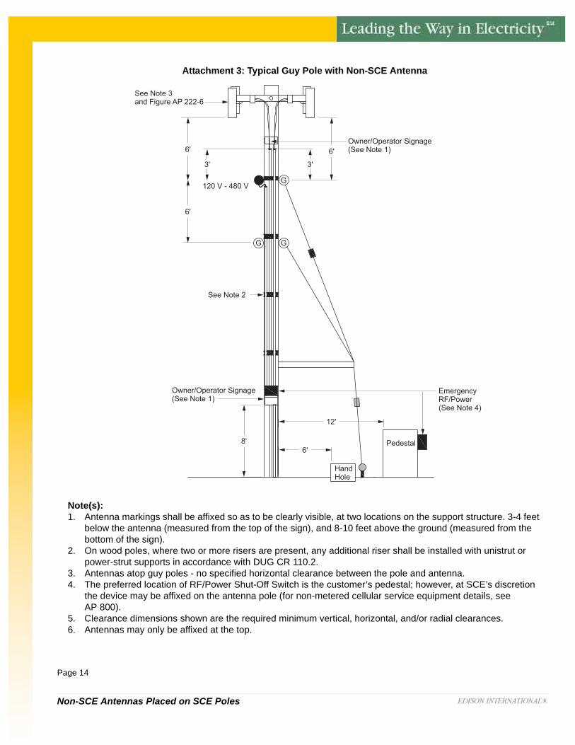
Attachment 3: Typical Guy Pole with Non-SCE Antenna
Note(s): 1. Antenna markings shall be affixed so as to be clearly visible, at two locations on the support structure. 3-4 feet
below the antenna (measured from the top of the sign), and 8-10 feet above the ground (measured from the bottom of the sign).
2. On wood poles, where two or more risers are present, any additional riser shall be installed with unistrut or power-strut supports in accordance with DUG CR 110.2.
3. Antennas atop guy poles - no specified horizontal clearance between the pole and antenna.4. The preferred location of RF/Power Shut-Off Switch is the customer’s pedestal; however, at SCE’s discretion
the device may be affixed on the antenna pole (for non-metered cellular service equipment details, see AP 800).
5. Clearance dimensions shown are the required minimum vertical, horizontal, and/or radial clearances.6. Antennas may only be affixed at the top.
See Note 3and Figure AP 222-6
Owner/Operator Signage(See Note 1)
Owner/Operator Signage(See Note 1)
120 V - 480 V
6'
8'6'
12'
G
See Note 2
EmergencyRF/Power(See Note 4)
Pedestal
HandHole
3'3'
6'
6'
GG

Non-SCE Antennas Placed on SCE Poles
Page 15
Attachment 4: Typical High Voltage Distribution Pole with Non-SCE Cable/Strand Mounted Omni Antenna
Note(s): 1. Antenna markings shall be affixed so as to be clearly visible, at two locations on the support structure. 3-4 feet below the
antenna (measured from the top of the sign), and 8-10 feet above the ground (measured from the bottom of the sign).2. On wood poles, where two or more risers are present, any additional riser shall be installed with unistrut or power-strut
supports in accordance with DUG CR 110.2.3. Unguarded communication cables below distribution lines (120-480 V) require 6 feet vertical clearance (measured from
centerline of conductor to centerline of nearest communication cable).4. Guarded communication cables below distribution lines (120-480 V) require 4 feet vertical clearance (measured from
centerline of conductor to centerline of nearest communication cable).5. The preferred location of RF/Power Shut-Off Switch is the customer’s pedestal; however, at SCE’s discretion the device
may be affixed on the antenna pole (for non-metered cellular service equipment details, see AP 800). 6. Clearance dimensions shown are the required minimum vertical, horizontal, and/or radial clearances.7. Cable/strand mounted antennas: Maximum length is 3 ft.
See Figure AP 222-6
Owner/Operator Signage(See Note 1)
8'6'
12'
See Note 2
EmergencyRF/Power(See Note 6)
Pedestal
HandHole
4' (MIN)120 V - 480 V
2.4 kV - 33 kV
10' (MIN)12'
6' (See Note 3 & 4)
6' (MIN)
Owner/Operator Signage(See Note 1)
Communication Cables

Non-SCE Antennas Placed on SCE Poles
Page 16
Attachment 5: Non-SCE Directional Antenna Between Transmission and Distribution Lines
Note(s): 1. All noted clearances are shown as minimums unless otherwise noted.2. Antenna markings shall be affixed so as to be clearly visible, at two locations on the support structure; 3-4 feet below the
antenna (measured from the top of the sign), and 8-10 feet above the ground (measured from the bottom of the sign).3. On wood poles, where two or more risers are present, any additional riser shall be installed with stand-off brackets.4. The top riser opening shall maintain a minimum distance of one (1) foot from guy attachments and a minimum distance of 6
feet from any distribution conductor below it.5. The preferred location of the Power Shutoff Switch is the customer's pedestal; however, at SCE's discretion, the device
may be affixed on the antenna pole. (For non-metered cellular service equipment details, refer to DOH AP 800.)6. Antennas shall maintain a minimum distance of 4 feet from guy attachments and a minimum distance of 6 feet from any
distribution conductor above or below it.

Non-SCE Antennas Placed on SCE Poles
Page 17
Attachment 6: Emergency RF/Power Shut-Off Switch
Attachment 7: Omni-Directional Antenna and Directional Antenna
Omni-Directional Antenna Directional Antenna

Non-SCE Antennas Placed on SCE Poles
Page 18
Attachment 8:Example of Non-SCE Cable/Strand Mounted Omni Antenna Attached to Communication Cables
Note(s): 1. For Non-SCE Cable/Strand Mounted Omni Antenna’s minimum clearance requirements, refer to Attachment 4.
Non-SCE Antennas Placed on SCE Poles
Page 19
7.0 Contact Information
Manual Access Information
The External Manual for Non-SCE Antennas Placed on Distribution Pole can be accessed and downloaded from the following SCE web site:
http://www.sce.com/AboutSCE/Regulatory/distributionmanuals/
Getting Help
If you have any comments, questions, or suggestions concerning this manual, please contact Joint Pole Organization at:

This page intentionally left blank.