penetrated structure for high-efficiency liquid ...acs paragon plus environment ... (pdms)/chns...
TRANSCRIPT

Subscriber access provided by NANJING POLYTECH UNIV
is published by the American Chemical Society. 1155 Sixteenth Street N.W.,Washington, DC 20036Published by American Chemical Society. Copyright © American Chemical Society.However, no copyright claim is made to original U.S. Government works, or worksproduced by employees of any Commonwealth realm Crown government in the courseof their duties.
Energy, Environmental, and Catalysis Applications
Ultrathin membranes with polymer/nanofiber inter-penetrated structure for high-efficiency liquid separations
Yufan Ji, Guining Chen, Guozhen Liu, Jing Zhao, Gongping Liu, Xuehong Gu, and Wanqin JinACS Appl. Mater. Interfaces, Just Accepted Manuscript • DOI: 10.1021/acsami.9b12445 • Publication Date (Web): 11 Sep 2019
Downloaded from pubs.acs.org on September 23, 2019
Just Accepted
“Just Accepted” manuscripts have been peer-reviewed and accepted for publication. They are postedonline prior to technical editing, formatting for publication and author proofing. The American ChemicalSociety provides “Just Accepted” as a service to the research community to expedite the disseminationof scientific material as soon as possible after acceptance. “Just Accepted” manuscripts appear infull in PDF format accompanied by an HTML abstract. “Just Accepted” manuscripts have been fullypeer reviewed, but should not be considered the official version of record. They are citable by theDigital Object Identifier (DOI®). “Just Accepted” is an optional service offered to authors. Therefore,the “Just Accepted” Web site may not include all articles that will be published in the journal. Aftera manuscript is technically edited and formatted, it will be removed from the “Just Accepted” Website and published as an ASAP article. Note that technical editing may introduce minor changesto the manuscript text and/or graphics which could affect content, and all legal disclaimers andethical guidelines that apply to the journal pertain. ACS cannot be held responsible for errors orconsequences arising from the use of information contained in these “Just Accepted” manuscripts.

1
Ultrathin Membranes with Polymer/Nanofiber Inter-penetrated
Structure for High-efficiency Liquid Separations
Yufan Ji, Guining Chen, Guozhen Liu, Jing Zhao*, Gongping Liu, Xuehong Gu, Wanqin
Jin*
State Key Laboratory of Materials-Oriented Chemical Engineering, College of Chemical
Engineering, Nanjing Tech University, 30 Puzhu South Road, Nanjing 211800, P.R. China
*To whom all correspondence should be addressed.
Tel.: +86-25-83172266; fax: +86-25-83172292.
E-mail: ([email protected]) or to W. Jin. ([email protected])
KEYWORDS:
Ultrathin polymer membrane, multi & alternate spin-coating, interface-decoration-layer,
inter-penetrated structure, liquid separation
Page 1 of 46
ACS Paragon Plus Environment
ACS Applied Materials & Interfaces
123456789101112131415161718192021222324252627282930313233343536373839404142434445464748495051525354555657585960

2
ABSTRACT
Ultrathin film composite (UTFC) membrane comprising an ultrathin polymeric active
layer has been extensively explored in gas separation applications benefiting from its
extraordinary permeation flux for high throughput separation. However, the practical
realization of ultrathin active layer in liquid separations is still impeded by the trade-off
effect between membrane thickness (permeation flux) and structural stability (separation
factor). Herein, we report a general multi & alternate spin-coating (MAS) strategy,
collaborating with the interface-decoration-layer of copper hydroxide nanofibers (CHNs)
to obtain ultrathin and robust polymer-based membranes for high-performance liquid
separations. The structural stability arises from the Polydimethylsiloxane (PDMS)/CHNs
inter-penetrated structure, which confers the synergistic effect between PDMS and CHNs
to concurrently resist PDMS swelling and avoid CHNs collapsing, while the ultrathin
thickness is enabled by the sub-10 nm pore size of CHNs layer, the rapid crosslinking
reaction during spin-coating and the small thickness of CHNs layer. As a result, the as-
prepared membrane possesses an exceptional butanol/water separation performance with
the flux of 6.18 kg/m2h and separation factor of 31, far exceeding the state-of-the-art
polymer membranes. The strategy delineated in this work provides a straightforward
method for the design of ultrathin and structurally stable polymer membranes, holding
great potentials for the practical application of high-efficiency separations.
Page 2 of 46
ACS Paragon Plus Environment
ACS Applied Materials & Interfaces
123456789101112131415161718192021222324252627282930313233343536373839404142434445464748495051525354555657585960

3
1. INTRODUCTION
Chemical separations account for a large proportion of the total energy consumption
in the world. In this light, developing energy-efficient separation technologies such as
membrane separation is imperative and of great significance for lowering global energy
cost, carbon emission and pollution.1, 2 The efficiency and the cost-competitiveness of
membrane separation technology essentially lie in the separation performance of
membrane materials.3, 4 Especially, a high permeation flux enables a high-throughput
separation, thus reducing membrane area, endowing a compact membrane equipment and
cutting down the capital cost. In recent years, mixed matrix membranes (MMMs)
containing inorganic fillers and polymeric matrices have been developed, which can
improve permeation flux via tuning free volume and introducing inorganic transport
pathways. 5-10 Theoretically, the permeation flux should be more remarkably influenced by
membrane thickness. As a consequence, fabricating an ultrathin active layer on top of a
porous support has been one of the most attractive research focuses, owing to its potential
to achieve excellent permeation flux. 11-21 However, the preparation and the practical
application of ultrathin active layer especially in liquid separations are still impeded by
some critical issues: 1) the severe solution intrusion into porous support due to the low
viscosity of polymer solution for thinner membrane, which leads to the generation of
defects in active layer; 2) the deteriorated membrane stability in liquid environment due to
the ultrathin thickness, which results in the collapsed membrane structure.22-25
In our previous work, a facile and universal interface-decoration-layer strategy was
Page 3 of 46
ACS Paragon Plus Environment
ACS Applied Materials & Interfaces
123456789101112131415161718192021222324252627282930313233343536373839404142434445464748495051525354555657585960

4
proposed to mitigate the solution intrusion phenomenon via depositing a copper hydroxide
nanofibers (CHNs) layer possessing high porosity, interconnected structure and sub-10-nm
pore size on porous support (Figure S1).26 Ultrathin thin film composite (UTFC)
membranes with the thickness of ~100 nm were obtained, achieving a 2.5-fold higher gas
permeance without the penalty of selectivity. Compared with gas separation, the various
separation systems in liquid environment exert more stringent requirements for membrane
stability due to the stronger permeating molecule-membrane interactions. PDMS is a
benchmark polymeric membrane material showing great potentials for gas separation and
solvent enrichment/recovery from dilute aqueous solution due to its good comprehensive
performance and cost-effective preparation.27-34 Although the PDMS-based membrane
prepared with the above-mentioned interface-decoration-layer strategy has displayed an
excellent gas separation performance, it almost shows no selectivity for organic
solvent/water separation due to the excessive swelling of ultrathin PDMS layer and the
collapsed CHNs network structure upon contacting with water and organic solvent
vapors.35, 36 Through prolonging pre-crosslinking time and increasing PDMS coating
amount, the membrane stability can be effectively improved, yet the consequent thickened
active layer inevitably leads to a lower permeation flux, which means there is a trade-off
phenomenon between membrane thickness (permeation flux) and structural stability
(separation factor).37, 38 So far, the application of ultrathin PDMS membrane in liquid
separations has rarely been reported
To address this issue, in this work, we proposed a novel multi & alternate spin-coating
Page 4 of 46
ACS Paragon Plus Environment
ACS Applied Materials & Interfaces
123456789101112131415161718192021222324252627282930313233343536373839404142434445464748495051525354555657585960

5
(MAS) strategy, collaborating with the CHNs interface-decoration-layer to obtain ultrathin
PDMS membranes for high-performance liquid separation with the butanol recovery from
aqueous solution as a model system. PDMS and cross-linking agent (tetraethyl orthosilicate,
TEOS) solutions were alternately and repeatedly spin-coated on the CHNs layer (Figure 1,
Figure S2). During each cycle of spin-coating, the low-viscosity PDMS solution will
penetrate into the pores of CHNs layer, and then form a crosslinked PDMS structure
wrapping the nanofibers during the subsequent coating of TEOS solution. On one hand,
the rigid CHNs network plays a critical role of physical confinement and interfacial
interlocking in resisting PDMS swelling. On the other hand, the PDMS provides a
protection for CHNs to avoid the direct contact of permeating molecules with CHNs.
Moreover, the thickness of PDMS/CHNs transition layer is limited to <200 nm, while an
ultrathin and defect-free PDMS active layer on top of CHNs layer can be formed due to
the sub-10 nm pore size of CHNs layer and the crosslinking reaction during spin-coating,
leading to a low total thickness. Consequently, the MAS strategy delineated herein realizes
an ultrathin thickness and a stable membrane structure concurrently, overcoming the trade-
off effect and achieving an attractive butanol/water separation performance.
Page 5 of 46
ACS Paragon Plus Environment
ACS Applied Materials & Interfaces
123456789101112131415161718192021222324252627282930313233343536373839404142434445464748495051525354555657585960

6
Figure 1. Schematic illustration of the membrane preparation process.
2. EXPERIMENTAL SECTION
2.1 Materials. PDMS (Mw = 60000) was manufactured from Shanghai Resin Factory
Co., Ltd. (China). N-heptane, tetraethyl orthosilicate (TEOS) and dibutyltin dilaurate
(DBTDL) were received from Sinopharm Chemical Reagent Co. Ltd. (China). Copper
nitrate and aminoethanol were purchased from Kanto Chemical Co. Ltd. (Japan). De-
ionized water generated in the laboratory were used for all the experiments. All chemicals
were of analytical grade and were used throughout without further purification. The
polyacrylonitrile (PAN) ultrafiltration membrane (molecular weight cut-off: 100 kDa) with
the flat-sheet configureuration was provided by Shandong MegaVision Membrane
Technology & Engineering Co. Ltd. (China).
2.2 Preparation of CHNs layer. Copper hydroxide nanofibers were prepared by
mixing an aqueous solution of 1.6 mM aminoethanol and an equivalent volume of 4 mM
copper nitrate solution and leaving it to age for 3 days at 25 oC. 10 ml of the as-synthesized
Page 6 of 46
ACS Paragon Plus Environment
ACS Applied Materials & Interfaces
123456789101112131415161718192021222324252627282930313233343536373839404142434445464748495051525354555657585960

7
CHNs dispersion was diluted to 30 ml with water, and then filtered on a PAN support by
vacuum filtration to obtain CHNs layer with the effective diameter of 4.0 cm.
2.3 Preparation of PDMS UTFC membranes. PDMS was added into n-heptane to
obtain a 10 wt% solution (solution A). The crosslinking agent TEOS (1 wt %) and the
catalyst dibutyltin dilaurate (DBTDL, 0.1 wt %) were dissolved in n-heptane (solution B).
Then the two resulting solutions were stirred at room temperature respectively for 30 min.
A certain amount of PDMS and TEOS–DBTDL solutions were alternately and repeatedly
spin-coated (500 rpm, 15s; 3000 rpm, 1 min) on the surface of CHNs layer to form an
active layer. The solutions were drop wise spin-coated during the 500 rpm stage. The as-
prepared membranes were named as PDMS(X)-Y/CHNs/PAN, where X represents the
total quantity of PDMS dropped on CHNs surface during spin-coating process (mg/cm2),
and Y represents the number of spin cycles. Y=0 refers to the membrane prepared through
single spin-coating of PDMS-TEOS-DBTDL mixed solution (with a pre-crosslinking time
of 36 or 48 h) as reported in the previous work.26 All the membranes were dried in air at
ambient temperature for 24 h, and then in a vacuum oven for 24 h to obtain the final
composite membranes.
2.4 Characterization. Transmission electron microscopy (TEM, JEOL-1010, an
accelerating voltage of 100 kV, JEM, USA) images and electron diffraction patterns were
obtained to observe the morphology and structure of nanofibers. The high-resolution
transmission electron microscopy (HR-TEM, JEOL-2000, an accelerating voltage of 200
kV, JEM, USA) images were also obtained. Morphologies of the as-prepared membranes
Page 7 of 46
ACS Paragon Plus Environment
ACS Applied Materials & Interfaces
123456789101112131415161718192021222324252627282930313233343536373839404142434445464748495051525354555657585960

8
were characterized by scanning electron microscope (FESEM, S4800, Hitachi, Japan) and
atomic force microscopy (AFM, XE-100, Park SYSTEMS, South Korea with non-contact
mode). For membrane thickness measurement, ten different locations in the cross-sectional
SEM images were measured and averaged to obtain the final result. X-ray photoelectron
spectroscopy (XPS, K-Alpha-MAGCIS, Thermo Scientific) depth analysis was performed
to investigate the solution intrusion phenomenon. For each sample, a step length of 15 nm
was employed to detect the elemental composition from membrane surface to interior in
the range of 0–400 nm. The water contact angles on the surface of membranes were tested
by a contact angle drop-meter (A100P, MAIST Vision Inspection & Measurement Co.,
Ltd.).
2.5 Butanol/water separation test. Recently, the emerging inadequacy of oil
resources and the growing demands on sustainable development have promoted the
production of renewable fuels from biomass such as bio-alcohols. Among the varied kinds
of valuable liquid biofuel, bio-butanol is main product of fermentation process. Therefore,
in this work, the butanol recovery from aqueous solution was chosen as a model system to
evaluate the performance of as-prepared PDMS-based membranes in liquid separation. The
butanol/water separation tests were performed with a home-made apparatus. The feed tank
was placed in a thermostat water bath to keep the temperature of the feed solution at a
steady state. The prepared flat-sheet PDMS-CHNs/PAN membrane was installed in a
stainless steel membrane module. The pressure of the permeate side was retained below
300 Pa via a vacuum pump, and the feed solution was sucked into membrane module at
Page 8 of 46
ACS Paragon Plus Environment
ACS Applied Materials & Interfaces
123456789101112131415161718192021222324252627282930313233343536373839404142434445464748495051525354555657585960

9
the flow rate of 60 L h-1 by a peristaltic pump. The permeated vapor was collected using a
cold trap with liquid nitrogen, and at least three samples were analyzed to ensure the
reliability of experimental results. The compositions of the feed and permeate were
analyzed by a gas chromatography (GC-2014, SHIMADZU, Japan). The total permeation
flux (J, kg/m2h) and separation factor (β) can be calculated according to the following
equations
(1) 𝐽 =𝑄
𝐴 ∗ 𝑡
(2) 𝛽 =𝑌𝑏 𝑌𝑤𝑋𝑏 𝑋𝑤
Where Q (kg) is the total mass of permeate collected in t hours, and A (m2) denotes
the effective area of the membrane. X and Y are the mass fractions of water (w) or butanol
(b) in feed and permeate sides, respectively.
2.6 Calculations of permeance (driving force-normalized form of flux) and
activation energy of permeation. The permeance of individual component (𝑃/𝑙) (GPU, 1
GPU=7.501×10⁻¹² m3 (STP)/m2 s pa) and selectivity (α) were calculated by following
equation:
(3) (𝑃/𝑙) 𝑖 = 𝐽𝑖
𝑝𝑖0 ― 𝑝𝑖𝑙=
𝐽𝑖
𝛾𝑖0𝑥𝑖0𝑝𝑠𝑎𝑡𝑖0 ― 𝑝𝑖𝑙
(4) 𝛼 =(𝑃 𝑙)𝑏
(𝑃 𝑙)𝑤
Where 𝐽𝑖 (kg/m2 h) is the permeation flux of component 𝑖; 𝑙 (m) is the thickness of
membrane; p𝑖0, 𝑝𝑖𝑙 (Pa) are the partial pressure of component 𝑖 in the feed side and permeate
side, respectively. 𝑝𝑖𝑙 can be taken the value of 0 for the high vacuum situation in the
Page 9 of 46
ACS Paragon Plus Environment
ACS Applied Materials & Interfaces
123456789101112131415161718192021222324252627282930313233343536373839404142434445464748495051525354555657585960

10
permeate side. 𝛾𝑖0 is the activity coefficient of component 𝑖 in the feed solution; 𝑥𝑖0 is the
mole fraction of component 𝑖 in the feed solution; (Pa) is the saturated vapor pressure 𝑝𝑠𝑎𝑡𝑖0
of pure component 𝑖.
The relationship between operating temperature and permeance usually conforms to
the Arrhenius law:
(5) (𝑃/𝑙) 𝑖 = (𝑃/𝑙)0exp (― 𝐸𝑃
𝑅𝑇 )
Where (𝑃/𝑙)𝑖 , (𝑃/l)0, EP, R and T represent the permeance of component 𝑖, the pre-
exponential factor, the activation energy, gas constant and feed temperature (K),
respectively.
3. RESULTS AND DISCUSSION
3.1. Characterizations of the CHNs and the PDMS-based UTFC membranes. The
nanofibers show a long and straight morphology (Figure 2a), and the width is estimated to
be around 4.2 nm (Figure 2b). On account of the extremely narrow structure, the electron
diffraction pattern is not very clear. However, the three weak halos still can be observed
attributable to the (111)/(002), (130), and (151) diffractions of orthorhombic Cu(OH)2
(Figure 2c).39 With a high-resolution TEM (HR-TEM) characterization on CHNs, the
spacing of 0.25 nm is clearly shown in the Figure 2d, indicating the (111) planes of
orthorhombic Cu(OH)2.
Page 10 of 46
ACS Paragon Plus Environment
ACS Applied Materials & Interfaces
123456789101112131415161718192021222324252627282930313233343536373839404142434445464748495051525354555657585960

11
Figure 2. TEM (a, b), SAED pattern (c) and HR-TEM (d) images of copper hydroxide
nanofibers.
As reported in the previous work, the CHNs layer is conducive to mitigate the solution
intrusion phenomenon, thus favoring the formation of an ultrathin and defect-free active
layer.26 Herein, CHNs/PAN support was prepared via depositing CHNs on PAN surface
with a fixed deposition amount of 0.8 ml/cm2. From the cross-sectional morphology of
CHNs(0.8)/PAN membrane, the CHNs layer shows good homogeneity with the thickness
around 200 nm (Figure S3). Subsequently, the PDMS and TEOS-DBTDL solutions were
alternately and repeatedly spin-coated on CHNs/PAN supports to form a series of PDMS-
based UTFC membranes. Figure 3 shows the surface and cross-section morphologies of
PDMS(X)-1/CHNs/PAN membranes with different PDMS spin-coating amounts. On
account of the low viscosity, PDMS solution will penetrate into the pores of CHNs layer
Page 11 of 46
ACS Paragon Plus Environment
ACS Applied Materials & Interfaces
123456789101112131415161718192021222324252627282930313233343536373839404142434445464748495051525354555657585960
12
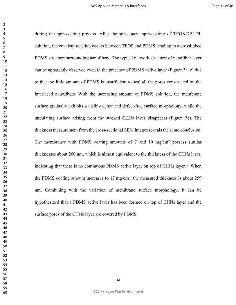
during the spin-coating process. After the subsequent spin-coating of TEOS-DBTDL
solution, the covalent reaction occurs between TEOS and PDMS, leading to a crosslinked
PDMS structure surrounding nanofibers. The typical network structure of nanofiber layer
can be apparently observed even in the presence of PDMS active layer (Figure 3a, c) due
to that too little amount of PDMS is insufficient to seal all the pores constructed by the
interlaced nanofibers. With the increasing amount of PDMS solution, the membrane
surface gradually exhibits a visibly dense and defect-free surface morphology, while the
undulating surface arising from the stacked CHNs layer disappears (Figure 3e). The
thickness measurement from the cross-sectional SEM images reveals the same conclusion.
The membranes with PDMS coating amounts of 7 and 10 mg/cm2 possess similar
thicknesses about 200 nm, which is almost equivalent to the thickness of the CHNs layer,
indicating that there is no continuous PDMS active layer on top of CHNs layer.26 When
the PDMS coating amount increases to 17 mg/cm2, the measured thickness is about 259
nm. Combining with the variation of membrane surface morphology, it can be
hypothesized that a PDMS active layer has been formed on top of CHNs layer and the
surface pores of the CHNs layer are covered by PDMS.
Page 12 of 46
ACS Paragon Plus Environment
ACS Applied Materials & Interfaces
123456789101112131415161718192021222324252627282930313233343536373839404142434445464748495051525354555657585960

13
Figure 3. FESEM images of the surface and cross-section of (a, b) PDMS(7)-1/CHNs/PAN;
(c, d) PDMS(10)-1/CHNs/PAN and (e, f) PDMS(17)-1/CHNs/PAN membranes.( The as-
prepared membranes were named as PDMS(X)-Y/CHNs/PAN, where X represents the
total quantity of PDMS in spin-coating solution (mg/cm2), and Y represents the number of
spin cycles.)
To further demonstrate this hypothesis, X-ray photoelectron spectroscopy (XPS)
depth analysis was performed to investigate the variation of elemental composition from
membrane surface to interior. As shown in Figure 4a, according to the change of silicon
(Si) and copper (Cu) elements with depth, the three-layer structure of PDMS(17)-
1/CHNs/PAN composite membrane can be clearly distinguished: (1) PDMS active layer in
the range of 0-75nm, where Si element content is high and constant, and Cu content is zero;
Page 13 of 46
ACS Paragon Plus Environment
ACS Applied Materials & Interfaces
123456789101112131415161718192021222324252627282930313233343536373839404142434445464748495051525354555657585960

14
(2) PDMS/CHNs transition layer in the range of 75-240 nm, where the content of Si starts
to decrease and then reaches a plateau region, while Cu element can be detected and also
reaches a plateau region; (3) PAN support after the etch depth of 240 nm, where both Cu
and Si contents remarkably decrease to approach zero. Comparatively, the PDMS(10)-
1/CHNs/PAN composite membrane shows a totally different phenomenon in the first stage:
in the range of 0-45 nm, the Si content is quite low (5-10 %), while the Cu content is higher
than the plateau region. The CHNs-dominant feature of this region evidences that the
nanopores in CHNs network has not been completely filled by PDMS, leaving some pores
exposed on membrane surface, which proves our assumption. In addition, for PDMS(10)-
1/CHNs/PAN and PDMS(17)-1/CHNs/PAN composite membranes, in the whole range of
the second stage, the phenomenon that Si content remarkably decreases and Cu content
remains quite high hasn’t been observed (for instance, the second stage of PDMS(20)-
0/CHNs/PAN membrane as shown in Figure S5, corresponding to the CHNs layer without
sufficient PDMS penetration). This result indicates that the CHNs layer is wrapped by
PDMS throughout the entire depth, which is conducive to protect CHNs from directly
contacting with permeating molecules and maintain membrane stability in liquid separation
environment. Although the one-cycle alternate spin-coating of PDMS and TEOS-DBTDL
solutions with PDMS coating amount of 10 mg/cm2 couldn’t form a defect-free PDMS
active layer, we obtained a completely different result when we divided the solutions into
6 equal parts and performed alternate spin-coating for 6 cycles (as shown in Figure 4a).
PDMS solution can fully cover the pores in CHNs layer and form a PDMS active layer
Page 14 of 46
ACS Paragon Plus Environment
ACS Applied Materials & Interfaces
123456789101112131415161718192021222324252627282930313233343536373839404142434445464748495051525354555657585960

15
with a thickness about 60 nm. The possible reason is that a cross-linked and solidified
PDMS structure can be formed after each cycle of alternate spin-coating due to the covalent
reaction between TEOS and PDMS, which gradually narrows the pore size, facilitates the
full coverage of the pores in CHNs layers and the formation of a continuous PDMS active
layer. For these membranes, the PDMS/CHNs transition layer also contributes to the
separation process since the CHNs pores are filled with PDMS. Therefore, the effective
membrane thickness should include both the thicknesses of PDMS active layer and
PDMS/CHNs transition layer.
Figure 4. XPS depth analysis results (a) and schematic illustrations of the cross-sectional
structures (b) of PDMS(17)-1/CHNs/PAN, PDMS(10)-1/CHNs/PAN and PDMS(10)-
6/CHNs/PAN membranes.
Page 15 of 46
ACS Paragon Plus Environment
ACS Applied Materials & Interfaces
123456789101112131415161718192021222324252627282930313233343536373839404142434445464748495051525354555657585960

16
The surface hydrophobicity of as-prepared composite membranes was investigated
since higher hydrophobicity would be beneficial for the butanol-preferential adsorption on
the membrane surface. Figure 5 shows the water contact angle values of the PDMS(17)-
1/CHNs/PAN membranes with the TEOS/PDMS mass ratio varying from 5 wt% to 40 wt%.
All the membranes are hydrophobic displaying the water contact angles higher than 90°. It
can be observed that there is an obvious increase from 90.4 o to 121.3 o when the
TEOS/PDMS mass ratio increases from 5 wt% to 20wt% since the intensified crosslinking
reaction consumes more hydroxyl groups on PDMS, thus leading to a higher
hydrophobicity. With the further increase of TEOS/PDMS mass ratio, the crosslinking
reaction between TEOS and PDMS tends to be saturated. The excessive TEOS molecules
are prone to carrying through the self-condensation reaction to generate SiO2 particles (as
shown in the AFM images in Figure S4) 40, 41. The Tyndall effect through PDMS-TEOS-
DBTDL mixed solution with TEOS/PDMS mass ratio of 40 wt% further evidences the
existence of SiO2 particles (Figure 5). The hydrophilic SiO2 particles result in the decrease
of hydrophobicity on the membrane surface.
Page 16 of 46
ACS Paragon Plus Environment
ACS Applied Materials & Interfaces
123456789101112131415161718192021222324252627282930313233343536373839404142434445464748495051525354555657585960
17
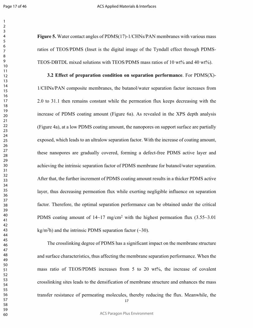
Figure 5. Water contact angles of PDMS(17)-1/CHNs/PAN membranes with various mass
ratios of TEOS/PDMS (Inset is the digital image of the Tyndall effect through PDMS-
TEOS-DBTDL mixed solutions with TEOS/PDMS mass ratios of 10 wt% and 40 wt%).
3.2 Effect of preparation condition on separation performance. For PDMS(X)-
1/CHNs/PAN composite membranes, the butanol/water separation factor increases from
2.0 to 31.1 then remains constant while the permeation flux keeps decreasing with the
increase of PDMS coating amount (Figure 6a). As revealed in the XPS depth analysis
(Figure 4a), at a low PDMS coating amount, the nanopores on support surface are partially
exposed, which leads to an ultralow separation factor. With the increase of coating amount,
these nanopores are gradually covered, forming a defect-free PDMS active layer and
achieving the intrinsic separation factor of PDMS membrane for butanol/water separation.
After that, the further increment of PDMS coating amount results in a thicker PDMS active
layer, thus decreasing permeation flux while exerting negligible influence on separation
factor. Therefore, the optimal separation performance can be obtained under the critical
PDMS coating amount of 14~17 mg/cm2 with the highest permeation flux (3.55~3.01
kg/m2h) and the intrinsic PDMS separation factor (~30).
The crosslinking degree of PDMS has a significant impact on the membrane structure
and surface characteristics, thus affecting the membrane separation performance. When the
mass ratio of TEOS/PDMS increases from 5 to 20 wt%, the increase of covalent
crosslinking sites leads to the densification of membrane structure and enhances the mass
transfer resistance of permeating molecules, thereby reducing the flux. Meanwhile, the
Page 17 of 46
ACS Paragon Plus Environment
ACS Applied Materials & Interfaces
123456789101112131415161718192021222324252627282930313233343536373839404142434445464748495051525354555657585960

18
consumption of hydroxyl groups on PDMS during crosslinking reaction improves the
hydrophobicity of membrane, promoting the selective adsorption towards butanol
molecules, and increasing the butanol/water separation factor. As the TEOS/PDMS mass
ratio continues to increase, the crosslinking reaction between TEOS and PDMS gradually
saturates, and SiO2 particles are generated from the self-condensation reaction of excessive
TEOS molecules. The hydrophilic SiO2 particles result in the decrease of hydrophobicity
on the membrane surface, which is not desirable for the preferential adsorption of butanol,
thus giving rise to the reduction of separation factor (Figure 6b). The effect of alternate
spin-coating number on the butanol/water separation performance was also investigated
with the total PDMS coating amount of 10 mg/cm2. The separation factor increases in the
first and then remains nearly unchanged with the increase of spin-coating cycle number,
while the total flux shows a reverse change tendency (Figure 6c). As demonstrated by the
XPS depth analysis, multiple cycles of alternate spin-coating facilitates the coverage of
pores in CHNs layer with PDMS and then leads to a defect-free PDMS active layer due to
the crosslinked and solidified PDMS structure formed in each cycle helps to narrow the
pore size. Therefore, the number of uncovered pores exposed on membrane surface
gradually declines with the increase of cycle number, leading to a decrease of unselective
pores for butanol/water permeation, thus increasing butanol/water separation factor and
decreasing flux until the intrinsic separation factor of PDMS membrane is reached. Since
the total spin-coating amount is same, once a defect-free PDMS layer can be formed, the
increase of spin-coating cycle number exert negligible influence on the separation
Page 18 of 46
ACS Paragon Plus Environment
ACS Applied Materials & Interfaces
123456789101112131415161718192021222324252627282930313233343536373839404142434445464748495051525354555657585960

19
performance. Similarly, the PDMS(17)-Y/CHNs/PAN composite membrane shows a
nearly constant performance with the increase of spin-coating cycle number (Figure S7).
Figure 6. Effect of (a) PDMS coating amount on the separation performance of PDMS(X)-
1/CHNs/PAN composite membrane; (b) TEOS/PDMS mass ratio on the separation
performance of PDMS(17)-1/CHNs/PAN composite membrane; (c) the number of spin
coating cycles on the separation performance of PDMS(10)-Y/CHNs/PAN composite
membrane; (d) Comparison on separation performance of M1 (PDMS(40)-
0/CHNs/PAN), M2 (PDMS(10)-6/CHNs/PAN), M3 (PDMS(17)-1/CHNs/PAN).
Butanol/water separation tests were performed at 40 °C with 1wt% butanol content in the
feed.
To verify the significance of multi & alternate spin-coating strategy in achieving high
Page 19 of 46
ACS Paragon Plus Environment
ACS Applied Materials & Interfaces
123456789101112131415161718192021222324252627282930313233343536373839404142434445464748495051525354555657585960

20
separation performance, the PDMS(X)-0/CHNs/PAN composite membranes were
prepared for comparison via direct spin-coating of PDMS-TEOS-DBTDL mixed solution
(Figure 6d). Furthermore, XPS depth analysis was also performed on the tested membranes
to investigate the evolution of membrane microstructure during butanol/water separation
(Figure 7a). At first, the PDMS(20)-0/CHNs/PAN membrane with a pre-crosslinking time
of 36 h was studied, since it has a ultrathin defect-free PDMS active layer which shows the
highest performance for gas separation.26 However, after 30 min of the separation test, the
membrane structure is damaged and the separation factor is sharply decreased to ~1. This
is mainly due to that the pore penetration in PDMS(20)-0/CHNs/PAN membrane is
inhibited via direct spin coating of mixed solution on CHNs layer (Figure S3), and thus the
CHNs layer is not sufficiently wrapped by PDMS. As a result, the ultrathin PDMS layer is
severely swollen during the butanol/water separation test, while the CHNs network
structure collapses after contacting with permeated vapors, which in turn aggregates the
destruction of PDMS layer (Figure 7b, Figure s6c). Both Si and Cu elements show sharply
fluctuated contents with the depth of PDMS(20)-0/CHNs/PAN membrane after test (Figure
7a), completely different with that before test (Figure S5), while the membrane surface
shows a cracked and defective morphology, sufficiently attesting the above hypothesis. In
contrast, the CHNs in the alternately spin-coated membranes are fully coated by PDMS
and a PDMS/CHNs transition layer is formed. The synergistic effect between PDMS and
CHNs confers high stability: (i) the rigid CHNs network provides mechanical support to
improve the swelling resistance of ultrathin PDMS layer via physical confinement and
Page 20 of 46
ACS Paragon Plus Environment
ACS Applied Materials & Interfaces
123456789101112131415161718192021222324252627282930313233343536373839404142434445464748495051525354555657585960

21
interfacial interlocking; (ii)the PDMS surrounding CHNs acts as a protection layer to avoid
the direct contact of vapors with CHNs and inhibit the collapsing of CHNs network (Figure
7c, Figure S6a, b). As a proof, the XPS depth profiles of PDMS(10)-6/CHNs/PAN and
PDMS(17)-1/CHNs/PAN membranes are exactly maintained after separation test (Figure
4a and Figure 7a). According to the above analysis on deteriorated performance of the
PDMS(20)-0/CHNs/PAN membrane with a pre-crosslinking time of 36 h, there are two
methods to improve the membrane stability: (i) increase the swelling resistance of PDMS
active layer; (ii) protect the CHNs with PDMS through pore penetration. The latter is
achieved with the multi & alternate spin-coating (MAS) strategy in this work. As a
comparison, we also tried the former method to show the superiority of the MAS strategy
via prolonging the pre-crosslinking time to 48 h. It is beneficial to enhance the crosslinking
degree and increased the PDMS coating amount to increase the thickness of active layer.
At the coating amount of 40 mg/cm2, the PDMS(40)-0/CHNs/PAN membrane (M1)
achieves the intrinsic butanol/water separation factor of PDMS membrane and shows an
acceptable stability during the separation test. In this case, the thickness of PDMS active
layer is around 1.5 μm (Figure S8). The much thicker active layer leads to a higher mass
transfer resistance. Therefore, the flux is only 1.45 kg/m2h, which is obviously lower than
that of the PDMS(10)-6/CHNs/PAN (M2) and PDMS(17)-1/CHNs/PAN (M3) membranes
(Figure 6d), confirming that multi & alternate spin-coating of PDMS and TEOS-DBTDL
solutions is an effective approach to achieving high flux. In comparison, the flux of
PDMS(10)-6/CHNs/PAN (M2) is slightly higher than that of PDMS(17)-1/CHNs/PAN
Page 21 of 46
ACS Paragon Plus Environment
ACS Applied Materials & Interfaces
123456789101112131415161718192021222324252627282930313233343536373839404142434445464748495051525354555657585960

22
(M3), which can be attributed to the thinner PDMS active layer in M2 and the resultant
lower mass transfer resistance. This result reveals that the defect-free PDMS active layer
obtained by multi & alternate spin-coating strategy can achieve higher flux with less total
coating amount.
Figure 7. (a) schematic illustration of the cross-sectional structure of PDMS(20)-
0/CHNs/PAN membrane before and after the butanol/water separation test; (b) XPS depth
analysis results of PDMS(17)-1/CHNs/PAN, PDMS(10)-1/CHNs/PAN and PDMS(10)-
6/CHNs/PAN membranes after the butanol/water separation test; (c) schematic illustration
of the cross-sectional structure of PDMS(10)-6/CHNs/PAN membrane before and after the
butanol/water separation test.
3.3 Effect of operation condition on separation performance. 3.3.1 Butanol
content in feed. The butanol content in feed is a key factor influencing the membrane
performance. As shown in Figure 8a, b, with the butanol content in feed varying from 0.5
to 4 wt%, the separation factor decreases from 42.4 to 31.3, and the total flux increases
from 2.70 to 4.14 kg/m2h at the operating temperature of 40 °C. According to the formula
Page 22 of 46
ACS Paragon Plus Environment
ACS Applied Materials & Interfaces
123456789101112131415161718192021222324252627282930313233343536373839404142434445464748495051525354555657585960

23
3, the calculation of separation factor is affected by butanol content in the feed, therefore
the butanol content in permeate is also listed in Figure 8b to analyze the actual influence
on separation efficiency, which shows an increasing tendency from 40.6 to 62.1 wt%. Since
the increase of the butanol content in feed confers different influences on the mass transfer
driving forces of butanol and water molecules, we calculated the permeance (the driving
force-normalized permeation flux) of water and butanol and the butanol/water selectivity
of the prepared membrane as listed in Table S2. With the butanol content in feed increasing,
the butanol permeance elevates marginally, while the water permeance is almost
unchanged, finally realizing an increase in selectivity. The constant water permeance
indicates that the increased butanol content doesn’t contribute to promote the swelling of
PDMS layer, demonstrating the stability of membrane structure. The increase in the butanol
permeance can be ascribed to the promoted butanol adsorption. When the butanol content
in feed is up to 4 wt %, the membrane shows the highest separation performance with the
permeation flux of 4.14 kg/m2h and the butanol content in permeate of 62.1 wt%.
Page 23 of 46
ACS Paragon Plus Environment
ACS Applied Materials & Interfaces
123456789101112131415161718192021222324252627282930313233343536373839404142434445464748495051525354555657585960

24
Figure 8. Effect of the butanol content in feed on separation performance of PDMS(17)-
1/CHNs/PAN composite membrane: (a) flux, (b) separation factor and butanol content in
permeate; (c) Effect of feed temperature on the separation performance of PDMS(17)-
1/CHNs/PAN composite membrane; (d) The Arrhenius plots of water permeance and
butanol permeance.
3.3.2 Operating temperature. The influence of operating temperature on the
separation performance of PDMS(17)-1/CHNs/PAN composite membrane is illustrated in
Figure 8c. With the increase of operating temperature, the flux remarkably increases while
the separation factor slightly decreases. When the temperature is up to 60 oC, the flux
reaches 6.18 kg/m2h and the separation factor is 31. Since temperature will have effects on
different aspects such as mass transfer driving force, membrane structure (molecular
Page 24 of 46
ACS Paragon Plus Environment
ACS Applied Materials & Interfaces
123456789101112131415161718192021222324252627282930313233343536373839404142434445464748495051525354555657585960

25
diffusion) and permeating molecule-membrane interaction (molecular adsorption), the
water and butanol permeance and selectivity are calculated as listed in Table S3 to analyze
the influence of temperature in depth. Furthermore, the apparent activation energies (Ep)
for water and butanol permeation are also calculated by Arrhenius equation (Figure 8d).
Both the butanol permeance and water permeance decrease with increased temperature,
indicating that the increase in the driving force makes a dominant contribution to the
improved flux. The negative activation energies of butanol and water demonstrate that both
the water permeation and butanol permeation through PDMS membrane are adsorption-
controlled processes. The negative effect of increasing temperature on molecular
adsorption is more significant than the positive effect on molecular diffusion. It also reveals
that the membrane structure is not obviously swollen and remains stable at high
temperatures.
3.3.3 Long-term operation test. The long-term operation stability is an important
factor determining the practical application of membranes, which is especially critical for
the composite membranes with a thin active layer on a porous support. Herein, the stability
of PDMS(17)-1/CHNs/PAN membrane was investigated with a continuous butanol/water
separation test up to 200 h (Figure 9a). The total flux and separation factor slightly fluctuate
in the range of 2.61-3.27 kg/m2h and 33.1-38.6, respectively. The desirable stability of as-
prepared composite membrane arises from the inter-penetrated PDMS/CHNs structure
through alternate spin-coating of TEOS and PDMS, indicating a potential application in
bio-alcohol recovery and organic solvent/water separations.
Page 25 of 46
ACS Paragon Plus Environment
ACS Applied Materials & Interfaces
123456789101112131415161718192021222324252627282930313233343536373839404142434445464748495051525354555657585960

26
Figure 9. (a) The long-term separation performance of the PDMS(17)-1/CHNs/PAN
composite membrane (at 40 °C, 1wt% butanol-water mixture with TEOS/PDMS mass ratio
of 20 wt%); (b) Performance comparison of polymer-based membranes in separating 1 wt%
n-butanol aqueous solution..
3.3.4 Comparison with other reported membranes for butanol recovery. PDMS is the
most widely used polymeric membrane material for solvent enrichment/recovery from
dilute aqueous solution. Herein, the performance of recently reported polymer-based
Page 26 of 46
ACS Paragon Plus Environment
ACS Applied Materials & Interfaces
123456789101112131415161718192021222324252627282930313233343536373839404142434445464748495051525354555657585960

27
membranes for butanol/water separation are summarized in Figure 9b and Table S4.42-55 In
addition, the performance of several inorganic membranes also listed in the Table S4.56, 57
Due to the ultrathin and sturdy PDMS layer from the MAS strategy in this work, the
PDMS/CHNs/PAN composite membranes show an excellent flux, which is 2-20 times
higher than that of reported PDMS membranes, and a comparable separation factor. On
basis of the as-prepared high-flux PDMS UTFC membranes, other well-developed
approaches such as incorporating porous nanofillers can be adopted to further optimize the
membrane microstructure and improve the separation performance. Furthermore, the
PDMS/CHNs/PAN membranes even possess a competitive performance when comparing
with the reported polymer-based mixed matrix membranes, demonstrating the great
potential of MAS strategy.
4. CONCLUSIONS
In this work, a novel multi & alternate spin-coating method was explored cooperating
with the CHNs interface-decoration-layer to achieve high-performance PDMS UTFC
membranes for liquid separation. Through the alternate deposition of PDMS and TEOS
solutions on top of CHNs layer, a PDMS/CHNs inter-penetrated structure can be formed,
which enables the robust membrane structure: (i) the rigid CHNs network improves the
swelling resistance of PDMS via physical confinement and strengthens the interfacial
interlocking between the active layer and CHNs layer; (ii) the PDMS wrapping CHNs
provides a barrier to avoid the direct contact of permeating molecules with CHNs and then
protects the CHNs network. In addition, the sub-10 nm pore size of CHNs layer and the
Page 27 of 46
ACS Paragon Plus Environment
ACS Applied Materials & Interfaces
123456789101112131415161718192021222324252627282930313233343536373839404142434445464748495051525354555657585960

28
crosslinking reaction during spin-coating facilitates the formation of an ultrathin and
defect-free PDMS active layer, while the thickness of CHNs layer endows a limitation on
the thickness of PDMS/CHNs transition layer to <200 nm, leading to a low total thickness.
The PDMS/CHNs/PAN membranes in this work show a superior performance with the
flux of 6.18 kg/m2h and the butanol/water separation factor of 31, outperforming the state-
of-the-art polymer-based membranes. The combination of MAS and interface-decoration-
layer strategies proposed here provides a promising approach for the production of ultrathin
membranes for high-efficiency liquid separations.
Page 28 of 46
ACS Paragon Plus Environment
ACS Applied Materials & Interfaces
123456789101112131415161718192021222324252627282930313233343536373839404142434445464748495051525354555657585960

29
ASSOCIATED CONTENT
Supporting Information
The Supporting Information is available free of charge on the ACS Publications website.
Schematic representations of the different membrane preparation processes and the PDMS
cross-linking reaction mechanism, FESEM images of substrate and CHNs layer, AFM
images of PDMS(17)-1/CHNs/PAN membranes with various TEOS/PDMS mass ratios,
XPS depth analysis results of PDMS(20)-0/CHNs/PAN membrane, FESEM images of the
membrane surfaces after test; Effect of the number of PDMS coating cycle on the PV
performance, Cross-sectional SEM images of PDMS(40)-0/CHNs/PAN(48h) composite
membrane, Water contact angles of PDMS(17)-1/CHNs/PAN membrane surface.
Permeance and selectivity data, performance comparison of the membrane in this work
with state-of-the-art membranes.
Page 29 of 46
ACS Paragon Plus Environment
ACS Applied Materials & Interfaces
123456789101112131415161718192021222324252627282930313233343536373839404142434445464748495051525354555657585960

30
AUTHOR INFORMATION
Corresponding Author
* [email protected] (Dr. J. Zhao)
* [email protected] (Prof. W. Jin)
Author Contributions
Contribution of each author: Wanqin Jin and Jing Zhao conceived the project. Yufan Ji
prepared the membranes, carried out the characterizations and water/butanol separation
tests. Guining Chen and Guozhen Liu assist me to complete the long-term operation test.
Yufan Ji and Jing Zhao conducted data analysis. Wanqin Jin, Jing Zhao, Gongping Liu and
Xuehong Gu participated in results discussion. All the authors were involved in writing the
manuscript.
ORCID
Jing Zhao: 0000-0002-1423-0291
Wanqin Jin: 0000-0001-8103-4883
Notes
The authors declare no competing financial interest.
Page 30 of 46
ACS Paragon Plus Environment
ACS Applied Materials & Interfaces
123456789101112131415161718192021222324252627282930313233343536373839404142434445464748495051525354555657585960

31
ACKNOWLEDGMENT
This work was financially supported by the National Natural Science Foundation of
China(21728601, 21490585, 21606123), the Natural Science Foundation of Jiangsu
Province (BK20160980), the Innovative Research Team Program by the Ministry of
Education of China (Grant no.IRT_17R54) and the Topnotch Academic Programs Project
of Jiangsu Higher Education Institutions (TAPP).
Page 31 of 46
ACS Paragon Plus Environment
ACS Applied Materials & Interfaces
123456789101112131415161718192021222324252627282930313233343536373839404142434445464748495051525354555657585960

32
REFERENCES 1. Sholl, D. S.; Lively, R. P., Seven chemical separations to change the world. Nature News, 2016, 532, 435-437.2. Xie, K.; Fu, Q.; Qiao, G. G.; Webley, P. A., Recent progress on fabrication methods of polymeric thin film gas separation membranes for CO2 capture. J. Membr. Sci., 2019, 572, 38-60.3. Drioli, E.; Stankiewicz, A. I.; Macedonio, F., Membrane engineering in process intensification—An overview. J. Membr. Sci., 2011, 380, 1-8.4. Gould, R. M.; White, L. S.; Wildemuth, C. R., Membrane separation in solvent lube dewaxing. Environ. Prog., 2001, 20, 12-16.5. Judd, S., The status of membrane bioreactor technology. Trends Biotechnol., 2008, 26, 109-116.6. Seidel, A.; Elimelech, M., Coupling between chemical and physical interactions in natural organic matter (NOM) fouling of nanofiltration membranes: implications for fouling control. J. Membr. Sci., 2003, 203, 245–255.7. Gao, Z.; Feng, Y.; Ma. D; Chung, T.-S., Vapor-phase crosslinked mixed matrix membranes with UiO-66-NH2 for organic solvent nanofiltration. J. Membr. Sci., 2019, 574, 124-135. 8. Xu, Y.; Japip, S.; Chung, T.-S., Mixed matrix membranes with nano-sized functional UiO-66-type MOFs embedded in 6FDA-HAB/DABA polyimide for dehydration of C1-C3 alcohols via pervaporation. J. Membr. Sci., 2018, 549, 217-226.9. Farahani, M. H. D. A.; Hua, D.; Chung, T.-S., Cross-linked mixed matrix membranes (MMMs) consisting of aminefunctionalized multi-walled carbon nanotubes and P84 polyimide for organic solvent nanofiltration (OSN) with enhanced flux. J. Membr. Sci., 2018, 548, 319-331. 10. Vane, M. L.; Namboodiri, V. V.; Bowen, T. C., Hydrophobic zeolite–silicone rubber mixed matrix membranes for ethanol–water separation: Effect of zeolite and silicone component selection on pervaporation performance. J. Membr. Sci., 2008, 308, 230-241.11. Zhang, Y.; Shen, Y.; Hou, J.; Zhang, Y.; Fam, W.; Liu, J.; Bennett, T. D.; Chen, V., Ultraselective pebax membranes enabled by templated microphase separation. ACS Appl. Mater. Interfaces, 2018, 10, 20006-20013.12. Zuo, J.; Chung, T.-S., Design and synthesis of a fluoro-silane amine monomer for novel thin film composite membranes to dehydrate ethanol via pervaporation. J. Mater. Chem. A, 2013, 1, 9814-9826.13. Ye, G.; Lee, J.; Perreault, F.; Elimelech, M., Controlled architecture of dual-functional block copolymer brushes on thin-film composite membranes for integrated "defending" and "attacking" strategies against biofouling. ACS Appl. Mater. Interfaces, 2015, 7, 23069-23079.14. Harris, J. J.; Stair, J. L.; Bruening, M. L., Layered polyelectrolyte films as selective, ultrathin barriers for anion transport. Chem. Mater., 2000, 12, 1941-1946.15. Gorgojo, P.; Karan, S.; Wong, H. C.; Jimenez-Solomon, M. F.; Cabral, J. T.; Livingston, A. G., Ultrathin polymer films with intrinsic microporosity: anomalous solvent permeation and high flux membranes. Adv. Funct. Mater., 2014, 24, 4729-4737.16. Zhu, Y.; Gao, S.; Hu, L.; Jin, J., Thermoresponsive ultrathin membranes with precisely tuned nanopores for high-flux separation. ACS Appl. Mater. Interfaces, 2016, 8, 13607-13614.17. Gao, S.; Zhu, Y.; Gong, Y.; Wang, Z.; Fang, W.; Jin, J., Ultrathin polyamide nanofiltration membrane fabricated on brush-painted single-walled carbon nanotube network support for ion sieving.
Page 32 of 46
ACS Paragon Plus Environment
ACS Applied Materials & Interfaces
123456789101112131415161718192021222324252627282930313233343536373839404142434445464748495051525354555657585960

33
ACS Nano, 2019, 13, 5278-5290.18. Shan, L.; Gu, J.; Fan, H.; Ji, S.; Zhang, G., Microphase diffusion-controlled interfacial polymerization for an ultrahigh permeability nanofiltration membrane. ACS Appl. Mater. Interfaces, 2017, 9, 44820-44827.19. Liu, M.; Nothling, M. D.; Webley, P. A.; Fu, Q.; Qiao, G. G., Postcombustion carbon capture using thin-film composite membranes. Acc. Chem. Res., 2019, 52, 1905-1914.20. Liu, M.; Xie, K.; Nothling, M. D.; Gurr, P. A.; Tan, S. S. L.; Fu, Q.; Webley, P. A.; Qiao, G. G., Ultrathin metal-organic framework nanosheets as a gutter layer for flexible composite gas separation membranes. ACS Nano, 2018, 12, 11591-11599.21. Xie, K.; Fu, Q.; Xu, C.; Lu, H.; Zhao, Q.; Curtain, R.; Gu, D.; Webley, P. A.; Qiao, G. G., Continuous assembly of a polymer on a metal–organic framework (CAP on MOF): a 30 nm thick polymeric gas separation membrane. Energy Environ. Sci., 2018, 11, 544-550.22. Zhao, J.; He, G.; Liu, G.; Pan, F.; Wu, H.; Jin, W.; Jiang, Z., Manipulation of interactions at membrane interfaces for energy and environmental applications. Prog. Polym. Sci., 2018, 80, 125-152.23. Tong, J.; Su, L.; Haraya, K.; Suda, H., Thin and defect-free Pd-based composite membrane without any interlayer and substrate penetration by a combined organic and inorganic process. Chem. Commun., 2006, 1142-1144.24. Huang, R. Y.M.; Pal, R.r.; Moon. G. Y., Crosslinked chitosan composite membrane for the pervaporation dehydration of alcohol mixtures and enhancement of structural stability of chitosan/polysulfone composite membranes. J. Membr. Sci., 1999, 160, 17-30.25. Dong, Z. Q.; Wang, B. J.; Ma, X. H.; Wei, Y. M.; Xu, Z. L., FAS grafted electrospun poly(vinyl alcohol) nanofiber membranes with robust superhydrophobicity for membrane distillation. ACS Appl. Mater. Interfaces, 2015, 7, 22652-22659.26. Ji, Y.; Zhang, M.; Guan, K.; Zhao, J.; Liu, G.; Jin, W., High‐performance CO2 capture through polymer‐based ultrathin membranes. Adv. Funct. Mater., 2019, 1900735.27. Fan, H.; Xie, Y.; Li, J.; Zhang, L.; Zheng, Q.; Zhang, G., Ultra-high selectivity COF-based membranes for biobutanol production. J. Mater. Chem. A, 2018, 6, 17602-17611 .28. Liu, W.; Hu, S.; Liu, G.; Pan, F.; Wu, H.; Jiang, Z.; Wang, B.; Li, Z.; Cao, X., Creation of hierarchical structures within membranes by incorporating mesoporous microcapsules for enhanced separation performance and stability. J. Mater. Chem. A, 2018, 6, 17602-17611.29. Fan, H.; Shi, Q.; Yan, H.; Ji, S.; Dong, J.; Zhang, G., Simultaneous spray self-assembly of highly loaded ZIF-8-PDMS nanohybrid membranes exhibiting exceptionally high biobutanol-permselective pervaporation. Angew. Chem., 2014, 53, 5578-5582.30. Qin, F.; Li, S.; Qin, P.; Karim, M. N.; Tan, T., A PDMS membrane with high pervaporation performance for the separation of furfural and its potential in industrial application. Green Chem., 2014, 16, 1262-1273.31. Van der Bruggen, B.; Luis, P., Pervaporation as a tool in chemical engineering: a new era?. Curr. Opin. Chem. Eng., 2014, 4, 47-53.32. Dobrak, A.; Figoli, A.; Chovau, S.; Galiano, F.; Simone, S.; Vankelecom, I. F.; Drioli, E.; Van der Bruggen, B., Performance of PDMS membranes in pervaporation: effect of silicalite fillers and comparison with SBS membranes. J. Colloid Interface Sci., 2010, 346, 254-264.
Page 33 of 46
ACS Paragon Plus Environment
ACS Applied Materials & Interfaces
123456789101112131415161718192021222324252627282930313233343536373839404142434445464748495051525354555657585960

34
33. Rozicka, A.; Niemistö, J.; Keiski, R. L.; Kujawski, W., Apparent and intrinsic properties of commercial PDMS based membranes in pervaporative removal of acetone, butanol and ethanol from binary aqueous mixtures. J. Membr. Sci., 2014, 453, 108-118.34. Rychlewska, K.; Kujawski, W.; Konieczny, K., Pervaporative removal of organosulfur compounds (OSCs) from gasoline using PEBA and PDMS based commercial hydrophobic membranes. Chem. Eng. J., 2017, 309, 435-444.35. Rumens, C. V.; Ziai, M. A.; Belsey, K. E.; Batchelor, J. C.; Holder, S. J., Swelling of PDMS networks in solvent vapours; applications for passive RFID wireless sensors. J. Mater. Chem. C, 2015, 3, 10091-10098.36. Mohammadi, T.; Aroujalian, A.; Bakhshi, A., Pervaporation of dilute alcoholic mixtures using PDMS membrane. Chem. Eng. Sci., 2005, 60, 1875-1880.37. Stafie, N.; Stamatialis, D. F.; Wessling, M., Effect of PDMS cross-linking degree on the permeation performance of PAN/PDMS composite nanofiltration membranes. Sep. Purif. Technol., 2005, 45, 220-231.38. Yin, J.; Deng, B., Polymer-matrix nanocomposite membranes for water treatment. J. Membr. Sci., 2015, 479, 256-275.39. Luo, Y.-H.; Huang, J.; Jin, J.; Peng, X.; Schmitt, W.; Ichinose, I., Formation of positively charged copper hydroxide nanostrands and their structural characterization. Chem. Mater., 2006, 18, 1795-180240. Stober, W.; Fink, A., Controlled growth of monodisperse silica spheres in the micron size range. J. Colloid Interface Sci., 1968, 26, 62-69.41. Xiangli, F.; Chen, Y.; Jin, W.; Xu, N., Polydimethylsiloxane (PDMS)/ceramic composite membrane with high flux for pervaporation of ethanol−water mixtures. Ind. Eng. Chem. Res., 2007, 46, 2224-2230.42. Dong, Z.; Liu, G.; Liu, S.; Liu, Z.; Jin, W., High performance ceramic hollow fiber supported PDMS composite pervaporation membrane for bio-butanol recovery. J. Membr. Sci., 2014, 450, 38-47.43. Liu, G.; Xiangli, F.; Wei, W.; Liu, S.; Jin, W., Improved performance of PDMS/ceramic composite pervaporation membranes by ZSM-5 homogeneously dispersed in PDMS via a surface graft/coating approach. Chem. Eng. J., 2011, 174, 495-503.44. Trinh, L. T. P.; Lee, Y. J.; Bae, H.-J.; Lee, H.-J., Pervaporative separation of butanol using a composite PDMS/PEI hollow fiber membrane. J. Ind. Eng. Chem., 2014, 20, 2814-2818.45. Niemistö, J.; Kujawski, W.; Keiski, R. L., Pervaporation performance of composite poly(dimethyl siloxane) membrane for butanol recovery from model solutions. J. Membr. Sci., 2013, 434, 55-64.46. Pan, Y.; Hang, Y.; Zhao, X.; Liu, G.; Jin, W., Optimizing separation performance and interfacial adhesion of PDMS/PVDF composite membranes for butanol recovery from aqueous solution. J. Membr. Sci., 2019, 579, 210-218.47. Bai, Y.; Dong, L.; Lin, J.; Zhu, Y.; Zhang, C.; Gu, J.; Sun, Y.; Xu, Y., High performance polydimethylsiloxane pervaporative membranes with hyperbranched polysiloxane as a crosslinker for separation of n-butanol from water. RSC Adv., 2015, 5, 52759-52768.48. Wang, X.; Chen, J.; Fang, M.; Wang, T.; Yu, L.; Li, J., ZIF-7/PDMS mixed matrix membranes for pervaporation recovery of butanol from aqueous solution. Sep. Purif. Technol., 2016, 163, 39-47.49. Mao, H.; Zhen, H.-G.; Ahmad, A.; Li, S.-H.; Liang, Y.; Ding, J.-F.; Wu, Y.; Li, L.-Z.; Zhao, Z.-
Page 34 of 46
ACS Paragon Plus Environment
ACS Applied Materials & Interfaces
123456789101112131415161718192021222324252627282930313233343536373839404142434445464748495051525354555657585960

35
P., Highly selective and robust PDMS mixed matrix membranes by embedding two-dimensional ZIF-L for alcohol permselective pervaporation. J. Membr. Sci., 2019, 582, 307-321.50. Liu, G.; Hung, W.-S.; Shen, J.; Li, Q.; Huang, Y.-H.; Jin, W.; Lee, K.-R.; Lai, J.-Y., Mixed matrix membranes with molecular-interaction-driven tunable free volumes for efficient bio-fuel recovery. J. Mater. Chem. A, 2015, 3, 4510-4521.51. Xue, C.; Du, G. Q.; Chen, L. J.; Ren, J. G.; Sun, J. X.; Bai, F. W.; Yang, S. T., A carbon nanotube filled polydimethylsiloxane hybrid membrane for enhanced butanol recovery. Sci. Rep., 2014, 4, 5925.52. Jonquieres, A.; Fane, A., Filled and unfilled composite GFT PDMS membranes for the recovery of butanols from dilute aqueous solutions: influence of alcohol polarity. J. Membr. Sci., 1997, 125, 245-255.53. Lee, J. Y.; Hwang, S. O.; Kim, H.-J.; Hong, D.-Y.; Lee, J. S.; Lee, J.-H., Hydrosilylation-based UV-curable polydimethylsiloxane pervaporation membranes for n-butanol recovery. Sep. Purif. Technol., 2019, 209, 383-391.54. Liu, S.; Liu, G.; Zhao, X.; Jin, W., Hydrophobic-ZIF-71 filled PEBA mixed matrix membranes for recovery of biobutanol via pervaporation. J. Membr. Sci., 2013, 446, 181-188.55. Yen, H. W.; Chen, Z. H.; Yang, I. K., Use of the composite membrane of poly(ether-block-amide) and carbon nanotubes (CNTs) in a pervaporation system incorporated with fermentation for butanol production by Clostridium acetobutylicum. Bioresour. Technol., 2012, 109, 105-109.56. Liu, Q.; Huang, B.; Huang, A., Polydopamine-based superhydrophobic membranes for biofuel recovery. J. Mater. Chem. A, 2013, 1, 11970-11974.57. Shen, D.; Xiao, W.; Yang, J. H.; Chu, N. B.; Lu, J. M.; Yin, D. H.; Wang, J. Q., Synthesis of silicalite-1 membrane with two silicon source by secondary growth method and its pervaporation performance. Sep. Purif. Technol. 2011, 76, 308−315.
Page 35 of 46
ACS Paragon Plus Environment
ACS Applied Materials & Interfaces
123456789101112131415161718192021222324252627282930313233343536373839404142434445464748495051525354555657585960

36
TOC graphic
Page 36 of 46
ACS Paragon Plus Environment
ACS Applied Materials & Interfaces
123456789101112131415161718192021222324252627282930313233343536373839404142434445464748495051525354555657585960

TOC
282x92mm (150 x 150 DPI)
Page 37 of 46
ACS Paragon Plus Environment
ACS Applied Materials & Interfaces
123456789101112131415161718192021222324252627282930313233343536373839404142434445464748495051525354555657585960

Figure 1. Schematic illustration of the membrane preparation process.
Page 38 of 46
ACS Paragon Plus Environment
ACS Applied Materials & Interfaces
123456789101112131415161718192021222324252627282930313233343536373839404142434445464748495051525354555657585960

Figure 2. TEM (a, b), SAED pattern (c) and HR-TEM (d) images of copper hydroxide nanofibers.
125x97mm (220 x 220 DPI)
Page 39 of 46
ACS Paragon Plus Environment
ACS Applied Materials & Interfaces
123456789101112131415161718192021222324252627282930313233343536373839404142434445464748495051525354555657585960
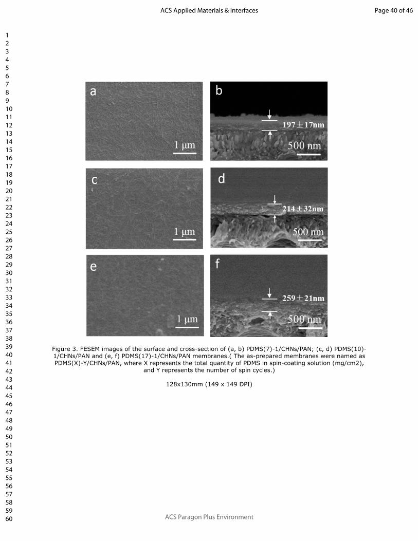
Figure 3. FESEM images of the surface and cross-section of (a, b) PDMS(7)-1/CHNs/PAN; (c, d) PDMS(10)-1/CHNs/PAN and (e, f) PDMS(17)-1/CHNs/PAN membranes.( The as-prepared membranes were named as PDMS(X)-Y/CHNs/PAN, where X represents the total quantity of PDMS in spin-coating solution (mg/cm2),
and Y represents the number of spin cycles.)
128x130mm (149 x 149 DPI)
Page 40 of 46
ACS Paragon Plus Environment
ACS Applied Materials & Interfaces
123456789101112131415161718192021222324252627282930313233343536373839404142434445464748495051525354555657585960

Figure 4. XPS depth analysis results (a) and schematic illustrations of the cross-sectional structures (b) of PDMS(17)-1/CHNs/PAN, PDMS(10)-1/CHNs/PAN and PDMS(10)-6/CHNs/PAN membranes.
279x190mm (150 x 150 DPI)
Page 41 of 46
ACS Paragon Plus Environment
ACS Applied Materials & Interfaces
123456789101112131415161718192021222324252627282930313233343536373839404142434445464748495051525354555657585960

Figure 5. Water contact angles of PDMS(17)-1/CHNs/PAN membranes with various mass ratios of TEOS/PDMS (Inset is the digital image of the Tyndall effect through PDMS-TEOS-DBTDL mixed solutions
with TEOS/PDMS mass ratios of 10 wt% and 40 wt%).
Page 42 of 46
ACS Paragon Plus Environment
ACS Applied Materials & Interfaces
123456789101112131415161718192021222324252627282930313233343536373839404142434445464748495051525354555657585960
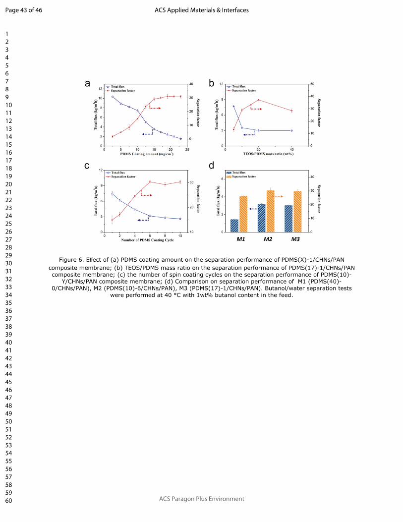
Figure 6. Effect of (a) PDMS coating amount on the separation performance of PDMS(X)-1/CHNs/PAN composite membrane; (b) TEOS/PDMS mass ratio on the separation performance of PDMS(17)-1/CHNs/PAN composite membrane; (c) the number of spin coating cycles on the separation performance of PDMS(10)-
Y/CHNs/PAN composite membrane; (d) Comparison on separation performance of M1 (PDMS(40)-0/CHNs/PAN), M2 (PDMS(10)-6/CHNs/PAN), M3 (PDMS(17)-1/CHNs/PAN). Butanol/water separation tests
were performed at 40 °C with 1wt% butanol content in the feed.
Page 43 of 46
ACS Paragon Plus Environment
ACS Applied Materials & Interfaces
123456789101112131415161718192021222324252627282930313233343536373839404142434445464748495051525354555657585960

Figure 7. (a) schematic illustration of the cross-sectional structure of PDMS(20)-0/CHNs/PAN membrane before and after the butanol/water separation test; (b) XPS depth analysis results of PDMS(17)-
1/CHNs/PAN, PDMS(10)-1/CHNs/PAN and PDMS(10)-6/CHNs/PAN membranes after the butanol/water separation test; (c) schematic illustration of the cross-sectional structure of PDMS(10)-6/CHNs/PAN
membrane before and after the butanol/water separation test.
425x176mm (150 x 150 DPI)
Page 44 of 46
ACS Paragon Plus Environment
ACS Applied Materials & Interfaces
123456789101112131415161718192021222324252627282930313233343536373839404142434445464748495051525354555657585960

Figure 8. Effect of the butanol content in feed on separation performance of PDMS(17)-1/CHNs/PAN composite membrane: (a) flux, (b) separation factor and butanol content in permeate; (c) Effect of feed temperature on the separation performance of PDMS(17)-1/CHNs/PAN composite membrane; (d) The
Arrhenius plots of water permeance and butanol permeance.
Page 45 of 46
ACS Paragon Plus Environment
ACS Applied Materials & Interfaces
123456789101112131415161718192021222324252627282930313233343536373839404142434445464748495051525354555657585960

Figure 9. (a) The long-term separation performance of the PDMS(17)-1/CHNs/PAN composite membrane (at 40 °C, 1wt% butanol-water mixture with TEOS/PDMS mass ratio of 20 wt%); (b) Performance comparison
of polymer-based membranes in separating 1 wt% n-butanol aqueous solution..
146x190mm (149 x 149 DPI)
Page 46 of 46
ACS Paragon Plus Environment
ACS Applied Materials & Interfaces
123456789101112131415161718192021222324252627282930313233343536373839404142434445464748495051525354555657585960