post-earthquake repair and improvements, san vicente, chile
DESCRIPTION
The magnitude 8.8 earthquake of February 2010 in Chile dealt a heavy blow to the 600 meter (2,000 ft) wharf structure at Berths 1, 2, and 3 of the San Vicente Terminal Internacional in the Biobio region of Chile. Earthquake-induced liquefaction and lateral spreading in the upland fill and wharf slope resulted in permanent wharf lateral deflections in excess of 600 mm (24 in), along with associated damage to concrete piling and pile-to-cap connections. This paper presents the post-earthquake repair and rehabilitation program for the wharf structure.TRANSCRIPT
POST-EARTHQUAKE REPAIR AND IMPROVEMENTS, SAN VICENTE, CHILE
John C. Bardi, PE, MASCE1, Jyotirmoy Sircar, PE, MASCE2, J. Paul Smith-Pardo, PhD,
PE, MASCE3
1Senior Project Manager, BergerABAM; 33301 Ninth Avenue South, Suite 300, Federal Way, WA 98003; PH (206) 431-2306; email: [email protected] Engineer, BergerABAM; 800 Gessner Road, Suite 1280, Houston, TX 77024; PH (832) 384-7814; email: [email protected] Professor, Seattle University; 901 12th Ave Seattle, WA 98122; PH (206) 296-5901; email: [email protected]
ABSTRACT
The magnitude 8.8 earthquake of February 2010 in Chile dealt a heavy blow to the 600 meter (2,000 ft) wharf structure at Berths 1, 2, and 3 of the San Vicente Terminal Internacional in the Biobio region of Chile. Earthquake-induced liquefaction and lateral spreading in the upland fill and wharf slope resulted in permanent wharf lateral deflections in excess of 600 mm (24 in), along with associated damage to concrete piling and pile-to-cap connections. This paper presents the post-earthquake repair and rehabilitation program for the wharf structure.
The proposed rehabilitation strategy consisted of two phases: first a structural assessment of the post-earthquake conditions, with recommendations for short-term repairs and restrictions on operating criteria, followed by a structural retrofit program designed to stiffen the existing structure and provide a new lateral-force resisting system. An innovative approach to the seismic retrofit was used, which incorporates a combination of new plumb piles behind the wharf with ground improvement to ensure ample lateral strength and ductility capacity of the structure.
The wharf retrofit also included a new apron structure in front of the wharf, designed to improve the local stability of existing slender piling (impacted by P-delta effects), with the added benefit of providing support for future crane rail installation and increased dredge depth. Finally, a 200 meter (656 ft) finger pier extension was included in the program, bringing the structurally retrofitted 4-berth system to a total combined 800 meters in length, designed to the most current seismic design standards.
INTRODUCTION
On 27 February 2010, a magnitude 8.8 earthquake struck central Chile, severely impacting the San Vicente (SVTI) container terminal. SVTI is approximately 90 km (150 mi) south west of the epicenter, located approximately 100 km (62 mi) northeast of the city of Concepcion. The earthquake caused lateral displacements in the existing wharf structures of up to 1.5 meters (4.9 ft) and in-plane torsional distortion along the 600 meter (2,000 ft) wharf superstructure; extensive settlement in nearly half the 20 hectare (50 ac)
container yard; and severe structural and nonstructural damage to warehouses and miscellaneous support building facilities.
The damage severely compromised the performance and operation of the facility and necessitated a complete assessment, repair, and rehabilitation program. The focus of this paper is to outline some of the techniques proposed for repair and rehabilitation of the damaged berth structure, which also included a new 200 meter (660 ft) finger pier extension in addition to rehabilitating the existing berth structure.
EXISTING CONFIGURATION AND EARTHQUAKE DAMAGE
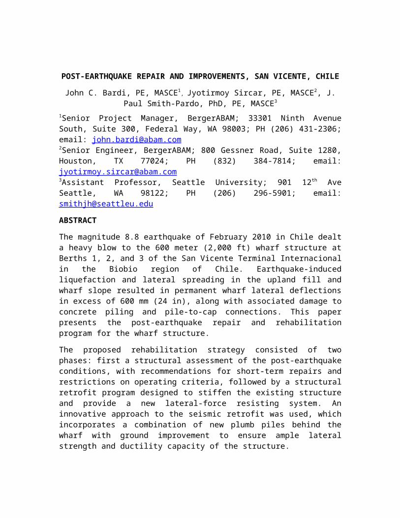
The existing SVTI wharf is a marginal structure consisting of three berths: 160 meter (530 ft) Berth 1, and 220 meters (720 ft) each at Berths 2 and 3. The wharf has three expansion joints that subdivide the structure in separate segments within each berth area. A reinforced concrete (RC) retaining wall at the back, supported on a gravity-type concrete caisson, provides containment to a relatively loose backfill with a thickness of 8 to 10 meters (26 to 33 ft). The fill is underlain by a layer of fine silty sands, which are in turn underlain by sedimentary rock. Subsurface data indicate that the top of rock elevation typically ranges from -18 to -20 meters (-59 to -66 ft) at the back of the wharf and from -25 to -28 meters (-82 to -92 ft) at the front of the wharf. Figure 1Figure 1 shows the site plan for the terminal including overall suggested repairs.
Figure 1. Overall Plan View of SVTI Structure Including Planned Upgrades
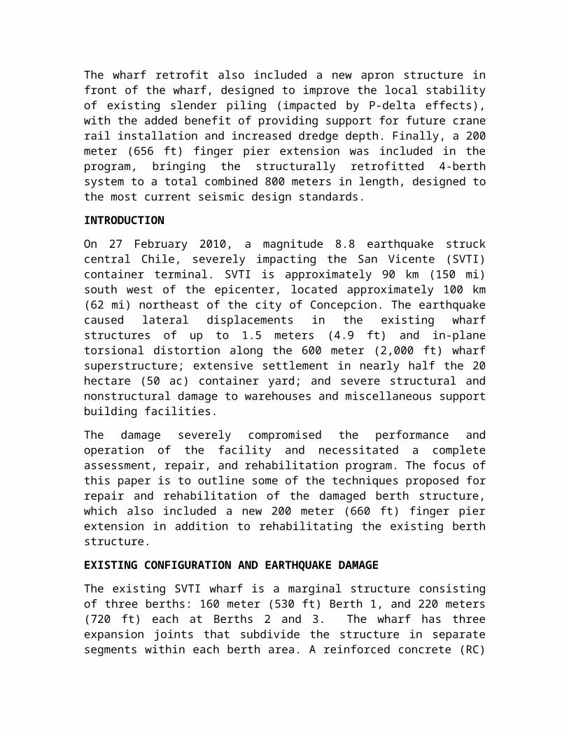
Berths 2 and 3. Berths 2 and 3 were constructed in the early 1970s and are composed of 500 mm square (20 in) precast (PC) pretensioned (PT) concrete piles, and 1,050 mm (42 in) diameter by 9.6 mm (3/8 in) thick steel pipe piles as the primary substructure supporting a concrete deck with bent spacing of 5 meters (16 ft), as shown in Figure 2. The PT concrete piles are located in the four outermost seaside pile rows, while the steel pipe piles are located along the two landside rows. The superstructure consists of 1,000 mm (39 inch) deep RC transverse pilecaps, two 1,000 mm (39 in) deep RC longitudinal
pilecaps supported by the steel pipe piles, six additional 600 mm (24 in) deep RC trapezoidal beams in the longitudinal direction, and a 400 mm (16 in) thick RC deck.
Figure 2: Cross Section of Existing Berths 2 and 3
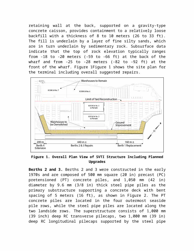
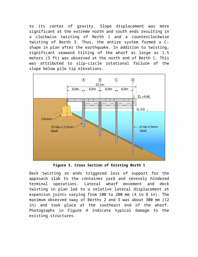
Berth 1. Berth 1 was constructed in 1993 and incorporates 1,020 mm (40 in) diameter by 12.5 mm (0.5 inch) thick steel pipe piles at the two landside rows and 610 mm (24 in) diameter by 10 mm (0.4 in) thick steel pipe piles at the two seaside rows, with spacing of 8.2 meters (27 ft). As shown on Figure 3, the piles are braced in the transverse direction with a system of 1,750 mm (69 in) deep steel trusses. In the longitudinal direction, the trusses are installed along the back two rows in a staggered fashion.
Earthquake-Induced Damage. Post-earthquake assessment revealed seaward movement of the wharf as a result of embankment subsidence, with twisting of the deck in plan. Movement of the slope is attributed to liquefaction and lateral spreading, and twisting of the deck occurred because the center of stiffness of the marginal wharf was eccentric to its center of gravity. Slope displacement was more significant at the extreme north and south ends resulting in a clockwise twisting of Berth 1 and a counterclockwise twisting of Berth 3. Thus, the entire system formed a C-shape in plan after the earthquake. In addition to twisting, significant seaward tilting of the wharf as large as 1.5 meters (5 ft) was observed at the north end of Berth 1. This was attributed to slip-circle rotational failure of the slope below pile tip elevations.
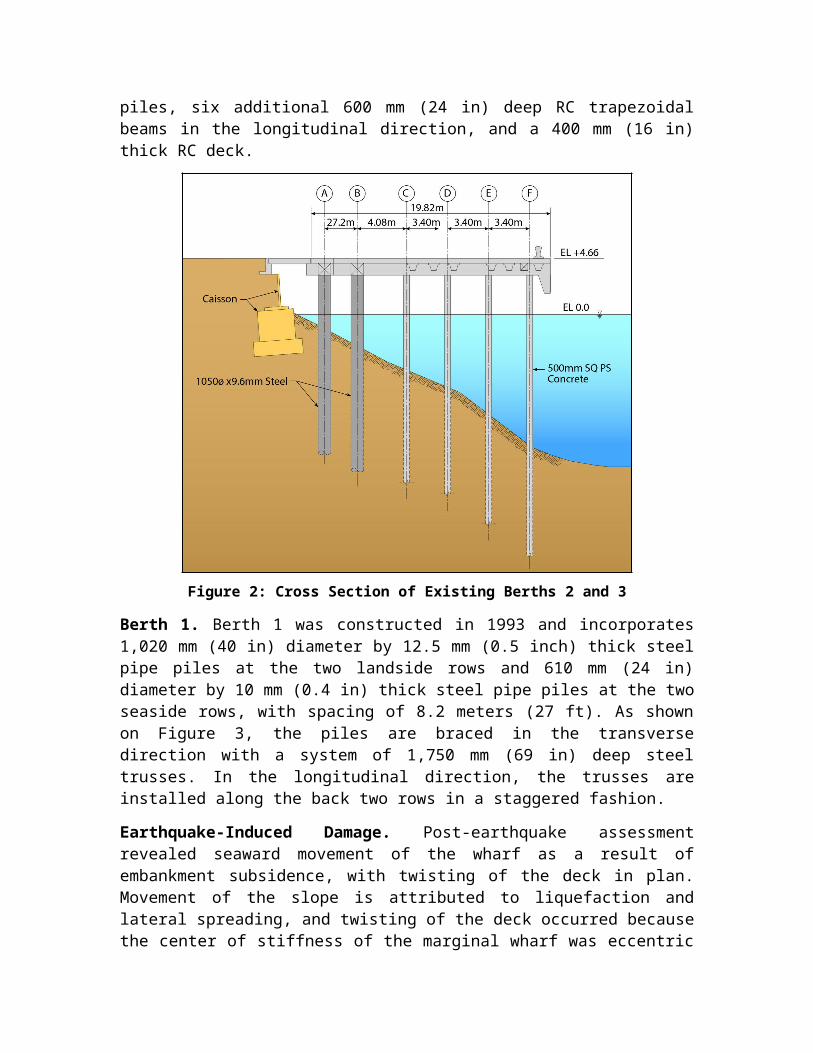
Figure 3. Cross Section of Existing Berth 1
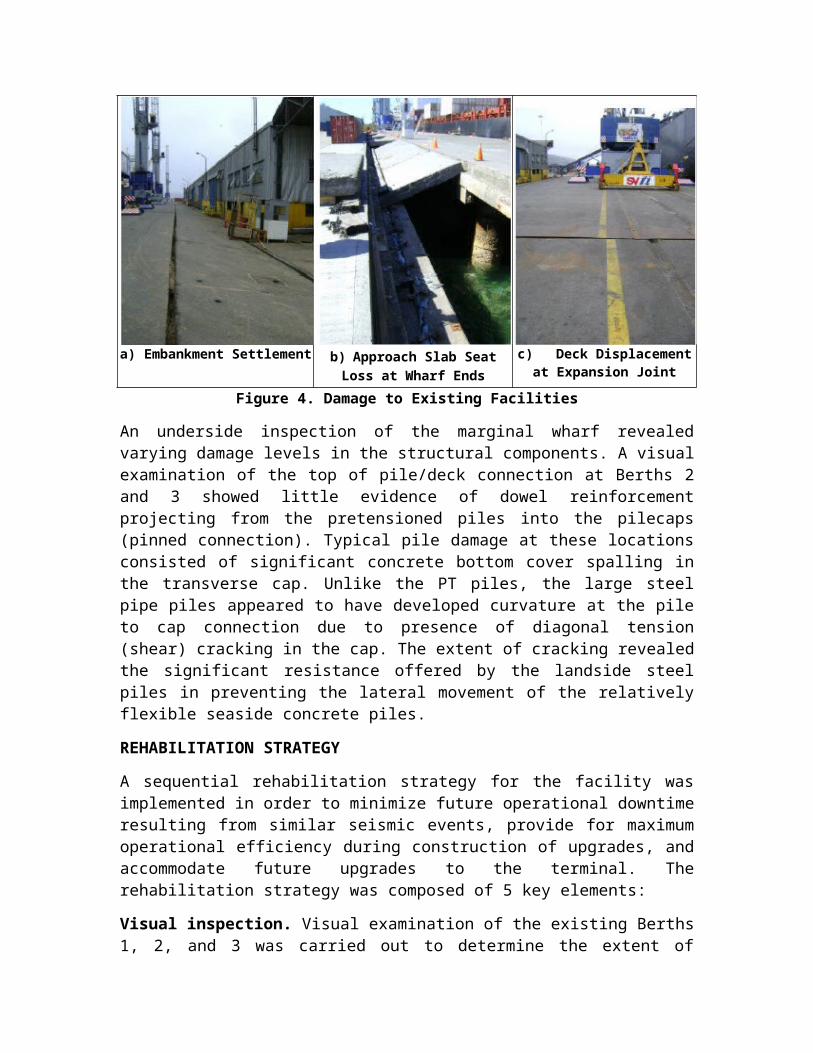
Deck twisting at ends triggered loss of support for the approach slab to the container yard and severely hindered terminal operations. Lateral wharf movement and deck twisting in plan led to a relative lateral displacement at expansion joints varying from 100 to 200 mm (4 to 8 in). The maximum observed sway of Berths 2 and 3 was about 300 mm (12 in) and took place at the southeast end of the wharf. Photographs in Figure 4 indicate typical damage to the existing structures.
a) Embankment Settlement b) Approach Slab Seat Loss at Wharf Ends
c) Deck Displacement at Expansion Joint
Figure 4. Damage to Existing Facilities
An underside inspection of the marginal wharf revealed varying damage levels in the structural components. A visual examination of the top of pile/deck connection at Berths 2 and 3 showed little evidence of dowel reinforcement projecting from the pretensioned piles into the pilecaps (pinned connection). Typical pile damage at these locations consisted of significant concrete bottom cover spalling in the transverse cap. Unlike the PT piles, the large steel pipe piles appeared to have developed curvature at the pile to cap connection due to presence of diagonal tension (shear) cracking in the cap. The extent of cracking revealed the significant resistance offered by the landside steel piles in preventing the lateral movement of the relatively flexible seaside concrete piles.
REHABILITATION STRATEGY
A sequential rehabilitation strategy for the facility was implemented in order to minimize future operational downtime resulting from similar seismic events, provide for maximum operational efficiency during construction of upgrades, and accommodate future upgrades to the terminal. The rehabilitation strategy was composed of 5 key elements:
Visual inspection. Visual examination of the existing Berths 1, 2, and 3 was carried out to determine the extent of damage and to isolate locations requiring complete reconstruction. Locations where minor or repairable damage occurred were identified and rehabilitation schemes were proposed. This included local pile and pilecap repairs designed to prevent the worsening of conditions due to the onset of corrosion in the short term.
Temporary Operation. Wide-flange beam available to the client were used to temporarily bridge the container yard to the wharf in zones where the transition slab had collapsed. In addition, it was recommended to use sand and crushed rock to temporarily regrade affected paved areas, but still restrict the circulation of heavy equipment. It was determined that the existing Berth 1 could not be used for any loaded mobile harbor crane operations because the extent of lateral displacement could compromise the stability of the structure. However, limited operations were possible on the existing Berths 2 and 3.
Ground Improvement. To mitigate the risk of future liquefaction-induced slope deformation, a ground improvement program was proposed for the 25 meter zone behind the existing marginal wharves. Stone columns were recommended as the preferred method because of local construction practice and the availability of materials. The improved zone was designed not only to stabilize upland fill and the area of the wharf slope, but also to provide a zone of stiff soil in which new plumb piles would be installed behind the existing wharf.
Structural Retrofit of Berths 1, 2, and 3. Because of the magnitude of pile and slope deformation at Berth 1, the stability of a rehabilitated structure was a concern even with proposed ground improvements in the fill behind the wharf. After analysis and review, replacement of the Berth 1 wharf structure was recommended. In the case of Berths 2 and 3, however, it was determined that the existing structures could be rehabilitated and retrofitted. The approach to strengthen the existing Berth 2 and 3 was to at least replace, if not enhance, the lateral stiffness and base shear capacity of the existing wharf, while improving capacity for lateral displacement. The use of additional pipe piles and a
doweled connection were found to be the best alternatives to ensure the desired stiffness, strength, and ductility of the wharf structure.
Construction of New Berth 4. The final stage of the wharf rehabilitation program included the construction of a 200 meter (656 ft) extension to the existing structure. This structure was proposed to be added to the south ends of the existing Berths 2 and 3 in order to provide additional flexibility and space for terminal operations. Because of the configuration of the upland area, the Berth 4 extension is in the form of a finger pier structure designed for two-sided berthing.
RETROFIT OF EXISTING BERTHS 1, 2 AND 3
The recommended structural rehabilitation of Berths 2 and 3 included the construction of a new integrated apron structure on the waterside and a link structure on the land side of the existing wharf structure (see Figure 5). The main function of the apron structure was to enhance local stability of the waterside portion of the wharf, while the link structure was designed to provide lateral stiffness, strength, and deformation capacity to the rehabilitated wharf. The apron structure will be supported on two 600 mm (24 in) diameter x 25 mm (1 in) thick steel pipe piles spaced every 6 meters (20 ft).
The link structure will be supported on two 900 mm (36 in) diameter by 20 mm (3/4 in) thick steel pipe piles spaced every 5 meters (16.4 ft), which in conjunction with the improved ground, form a new lateral-force resisting system designed for the seismic demand of the combined existing and new structures. Waterside piles at the link structure were proposed to be aligned with the existing piles such that pile spacing along that particular gridline would become 2.5 meters (8.2 feet). This scheme was intended to allow for future installation of land side crane rail for ship-to-shore (STS) terminal operations and upgrades.
A moment connection consisting of a circular confined RC plug reinforced with dowels and closely spaced spirals was proposed as the pile connection to the deck because of its proven performance in providing ductility during high seismic events. The effect of the steel pipe pile in providing confinement to the concrete plug is reflected in the higher strain limits recommended in relevant design standards such as MOTEM and the Port of Long Beach Wharf Design Criteria (POLB 2009) for this type of connection. For a contingency-level ground motion (CLE), strain limits were 0.025 for confined concrete and 0.06 for dowels. Additionally, the existing deck was proposed to be scarified and new high strength structural topping was proposed to be placed with continuity provided by installing new dowels. This overall scheme was found to provide significant structural capacity and performance as well as allow for maximum operational flexibility to Berths 2 and 3.
Figure 5. Proposed Retrofit for Berths 2 and 3
Evaluation of the P-delta effects on the existing (as-deformed) Berth 1 piling and the rated load capacity of the damaged deck structure revealed that the existing structure had little capacity to resist required vertical and/or lateral loads, and therefore replacement of the wharf structure was recommended. This necessitated the demolition of the entire existing superstructure, though the existing piling was proposed to be left in place.
Figure 6 presents a section view of the retrofit/replacement scheme. The concept is similar to that of Berths 2 and 3 in that the new lateral-force resisting system is still provided by the plumb piles driven into improved soil, and the apron structure zone is framed in the same way. In essence the proposed Berth 1 wharf differs only in that the wharf structure between the link and apron structures is also new.
The demolition of the superstructure was planned sequentially in order to take advantage of the existing structure as a work platform for the installation of new piling. The outermost landside pile was spaced at 5 meters (16.4 ft) on center while the inner landside pile was spaced at 2.5 meters (8.2 ft) on center. Five new 600 mm (24 in) diameter by 25 mm (1 in) thick steel pipe piles provided at each bent serve as the new substructure. Similar to Berths 2 and 3, the pile connection to the deck would be achieved using a ductile RC plug reinforced with dowels and closely spaced spirals. The new superstructure consisted of RC pilecaps supporting PC/PT deck panels and a RC topping. A new RC crane beam was proposed to be installed on the landside. The interface with the transverse bent spaced at 6.25 meters (20 ft), the new crane beam, and the piles was proposed to be achieved through a link structure similar to the one proposed at Berths 2 and 3. In addition, allowance was provided for a possible future construction of a crane beam on the waterside.
Figure 6. Proposed Retrofit for Berth 1
BERTH 4 EXTENSION
The proposed structural concept for Berth 4 consisted of using driven 900 mm (36 in) diameter by 20 mm (3/4 in) thick steel pipe piles as the primary substructure components. The typical pile (and bent) spacing is 7.5 meters (24.6 ft) except under the crane beam where piles are placed every 2.5 meters (8.2 ft). The additional piles serve to provide necessary vertical resistance for future container crane loads and also to increase the overall lateral resistance of the structure. Similar to Berths 1, 2 and 3, pile connection to the deck is proposed to be made via a ductile RC plug reinforced with dowels and closely spaced spirals. The new superstructure consisted of using RC transverse pilecaps at each bent supporting PC deck panels and a cast-in-place RC topping. Figure 7 presents a section view of the proposed structural concept for the new Berth 4.
As expected, the lateral response of the Berth 4 finger pier alone is intrinsically more flexible than that of Berths 1, 2 and 3, which have a marginal configuration. In order to alleviate this potential disparity in stiffness, it was decided to use larger 900 mm (36 in) diameter by 20 mm (3/4 in) pile sections throughout the Berth 4 structure.
Because the intent was to provide a continuous structure between the new Berth 4 and the existing Berths 1, 2, and 3, the flexible response of Berth 4 imposes significant demands on the stiffer perimeter landside piles of Berths 3 during a seismic event. Additional concerns associated to this stiffness disparity included the proper joint detailing between the existing wharves and new pier, and the design of the deck diaphragm. These issues were addressed with a special pile-to-deck connection near the end of Berth 3 at the first few bents of Berth 4 nearest to the existing structure, with additional diaphragm reinforcement and the inclusion of chord members in the Berth 3-4 transition zone.
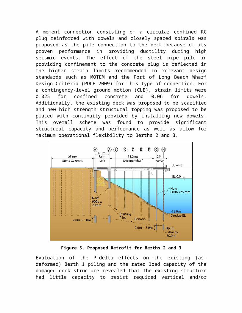
Figure 7. Proposed Structural Concept for Berth 4 Extension
To address the relative flexibility of the structure at the far (deeper) end of the finger pier, an underwater rock dike was proposed as a cost-effective way to shorten the exposed height of piling and increase transverse stiffness. Analysis showed that providing a prism consisting of well-graded rock (150 mm to 200 mm size) over the last 40 meters (131 feet) at the south end of Berth 4 provided the best global response. Analysis of the new pier revealed that the piles essentially remained elastic during the OLE with some hinging in the pile-to-cap connections occurring during the CLE. In general, the proposed new design successfully met all service, ultimate, and seismic design limits required POLB, MOTEMS, and the Chilean national seismic requirements (NCh 2369). Additionally, the new designs were considered to be fairly cost-effective, simple to fabricate, detail, and construct.
CONSTRUCTION
At the time of the preparation of this paper, the construction program was getting underway. The work is being carefully sequenced in order to prevent disruption to existing terminal operations which, while limited from the standpoint of allowable loading on the damaged wharves, have been steady since the earthquake. Work is scheduled to begin with the Berth 4 extension, while operations continue in Berths 2 and 3. Subsequently, work may shift to the replacement of Berth 1 in order to provide additional operating space while the final phases of reconstruction at Berths 2 and 3 are performed.
Special coordination and engineering detailing will be provided in order to smooth the construction process. As an example, special details will be incorporated in order to provide a consistent face of fender as the new apron structures are constructed. Additionally, details will provide for occupancy of Berths 2 and 3 as necessary during construction, should space available at Berths 1 and 4 be insufficient.
CONCLUSIONS
Damage resulting from the magnitude 8.8 earthquake in Concepcion, Chile, posed a serious threat to ongoing operations at the SVTI terminal. In the aftermath of the event, a rapid, coordinated response on the part of the terminal operator and the design team was required in order to assess damage, make immediate repairs, and plan for the eventual full rehabilitation of the wharf structures.
A relatively simple retrofitting scheme was ultimately adopted, consisting of the installation of two smaller enclosing structures in front and behind the existing wharf, with the structure in front improving stability, and the structure behind providing a new lateral-force resisting system with capacity equal to or greater than the original structure. The repair scheme also offers potential improved terminal operations in that it allows for future ship-to-shore crane operations.
Careful planning and consideration was devoted to the design of required repairs, not only to make effective use of the existing structures, but to allow as much continued operation as possible during construction.
REFERENCES
California State Lands Commission Marine Facilities Division. (2010). The Marine Oil Terminal Engineering and Maintenance Standards, codified as Chapter 31F (Marine Oil Terminals) (MOTEMS), Title 24, California Code of Regulations, Part 2, California Building Code.
NCh2369 (2003). Diseño sismico de estructuras e instalaciones industriales, norma chilena oficial, Chile.
Port of Long Beach (POLB). (2009). Port of Long Beach Wharf Design Criteria, Version 2.0. http://www.polb.com/economics/contractors/rfq_rfp/resources.asp. January 30, 2009.