power generation 1 siemens power generation 2003. all rights reserved 01/06/2015 “zero emission...
Post on 18-Dec-2015
222 views
TRANSCRIPT

Power Generation 1
S
iem
ens
Pow
er G
ener
atio
n 20
03.
All
Rig
hts
Res
erve
d
04/18/23
“Zero emission power plants”Torsten Strand

Power Generation 2
S
iem
ens
Pow
er G
ener
atio
n 20
03.
All
Rig
hts
Res
erve
d
04/18/23
Content
Introduction What is a zero emission plant?
No NOx and no CO2 emissions?Using a renewable fuel?
Some technologies for NOx reduction combustion modifications clean up systems
Some different technologies for CO2 capture combustion modifications = oxidation of fuel
mixed conducting membranes chemical looping
absorption fuel modifications
Combinations of NOx reduction and CO2 capture

Power Generation 3
S
iem
ens
Pow
er G
ener
atio
n 20
03.
All
Rig
hts
Res
erve
d
04/18/23
What is the best way to reduce CO2
In the global perspective the power industry seems to be able to prove that efficiency improvement in power production is enormously more important thanChange of fuelCO2 sequestration
What do you think???

Power Generation 4
S
iem
ens
Pow
er G
ener
atio
n 20
03.
All
Rig
hts
Res
erve
d
04/18/23
Coal fired steam turbine plants
The efficiency of such plants have a wide range going from a small back pressure plant e = 24 % tot = 90% An advanced high pressure condensing plant with three pressure levels and
double reheat e = 46 % tot = 46%
The next step is coal gasification with a gas turbine + steam turbine in combined cycle, but this step has not been really commercial in spite of many years of R&D
The hope for the “gasification club” is now to combine gasification with synthetic fuel production

Power Generation 5
S
iem
ens
Pow
er G
ener
atio
n 20
03.
All
Rig
hts
Res
erve
d
04/18/23
Case 1Gas Turbine in Simple Cycle
100 % fuel
Gas Turbine
63.6 % losses
36.4 % electricity

Power Generation 6
S
iem
ens
Pow
er G
ener
atio
n 20
03.
All
Rig
hts
Res
erve
d
04/18/23
100 % fuel
1-pressure HRSG
Gas Turbine
Case 2Gas Turbine in Cogeneration Cycle
12 % losses
35.9 % electricity
52.2 % process heat

Power Generation 7
S
iem
ens
Pow
er G
ener
atio
n 20
03.
All
Rig
hts
Res
erve
d
04/18/23
Steam Turbine (condensing)
100 % fuel
15 deg CGas Turbine
Case 3Gas Turbine in Combined Cycle
2-pressure HRSG
520 deg C
27 deg C
31 deg C31 deg C
12 % losses
35.9 % electricity
16.8 % electricity
35 % losses

Power Generation 8
S
iem
ens
Pow
er G
ener
atio
n 20
03.
All
Rig
hts
Res
erve
d
04/18/23
100 % fuel
Gas Turbine
Steam Turbine (district heating)
90 deg C
60 deg C
2-pressure HRSG
Case 4Gas Turbine in Combined Cycle
510 deg C
78 deg C
78 deg C
11 % losses
35.9 % electricity
11.3 % electricity 42.1 %
heat

Power Generation 9
S
iem
ens
Pow
er G
ener
atio
n 20
03.
All
Rig
hts
Res
erve
d
04/18/23
What is a zero emission power plant
Power plant emissions can be Unwanted content in the exhaust gas (CO2, NOx, CO, VOC, SO2, dioxin,
smoke, particles, steam plume…..) Ash, cooling water, spill water, lube oil Noise and vibrations Transports of fuel and ash, fuel preparation
In a Zero emission power plant all emissions but CO2 are low as a result of good engineering required by
laws, directives and regulations
Some claim that the emissions from transport and preparation of fuels is not considered in the right way when making assessment of different technologies
Is a bio mass fueled plant CO2 free? It was anyway considered CO2 neutral in many countries
up to some weeks ago when it was shown that forests produce methane
Is CO2 sequestration from a bio mass fuel plant unnecessary?

Power Generation 10
S
iem
ens
Pow
er G
ener
atio
n 20
03.
All
Rig
hts
Res
erve
d
04/18/23
The bio fuels = CO2 neutral fuels
Today’s sorted municipal waste and biomass are rather similar when seen as an energy source
Heating value Waste: 5 -17 MJ/kg (oil has 44 HJ/kg)Wood chips: 18 MJ/kg
Contain corrosive elementsWaste: alkali metals, ammonia, chlorides, metal vaporsBiomass: alkali metals, ammonia
Power production from bio mass is low, mostly only heating
Ways for power production Bio mass fired boilers with steam production for steam turbine Bio mass fired gas turbine with exhaust boiler and steam turbine Bio mass gasification + gas turbine with exhaust boiler and steam
turbine

Power Generation 11
S
iem
ens
Pow
er G
ener
atio
n 20
03.
All
Rig
hts
Res
erve
d
04/18/23
The new boiler at Garstad

Power Generation 12
S
iem
ens
Pow
er G
ener
atio
n 20
03.
All
Rig
hts
Res
erve
d
04/18/23
The original incineration boiler
1. Waste dump
2. Crane3. Grate4. Fan
5. Ash cooler6. Steam generator
7. Exhaust gas recirculation8. Urea injection
9. Electrostatic particle filter 10. Scrubber11. Cooler12. Air preheater
13. Water treatment14. Ca +ash injection15. Textile filter16. Fan17. Stack

Power Generation 13
S
iem
ens
Pow
er G
ener
atio
n 20
03.
All
Rig
hts
Res
erve
d
04/18/23
Bio mass boiler with gas turbine as fan for combustion air
Wood powder fired gas turbine for production of hot combustion gas for the bio mass boiler
Enakraft project in Enköping

Power Generation 14
S
iem
ens
Pow
er G
ener
atio
n 20
03.
All
Rig
hts
Res
erve
d
04/18/23
Bio oils & alcohols
Will bio oils or alcohols ever become a fuel for electricity production? A 15 MW gas turbine will consume almost all rape seed oil that is
produced in Sweden Palm oil is one of the best candidates, since it is really not suitable
for use in foodBut the palm oil plantations are said to ruin land in the Far East and
China!!Palm oil can be refined to different levels of purity. Rather crude palm oil
has been used in diesel enginesRefined palm oil can be burned in gas turbines
Ethanol from cane sugar industry has off and on come up as a gas turbine fuel in Brazil, but now it will be all consumed in cars
Ethanol can be burned in gas turbines

Power Generation 15
S
iem
ens
Pow
er G
ener
atio
n 20
03.
All
Rig
hts
Res
erve
d
04/18/23
Black liquor
Black liquor is a byproduct in the pulp industry Contains lignin and cellulose fibers by also all the alkali metals
concentrated, which makes it very corrosive when fired The Soda boilers are producing low temperature steam which is not
so good for electricity production in steam turbines
Gasification of black liquor has been a topic for year: Gasify and wash the gas from alkali and ammonia Burn in a high efficiency combined cycle
Lately the focus has shifted to Gasify and make DME for replacement of diesel in transport sector Burn the rest

Power Generation 16
S
iem
ens
Pow
er G
ener
atio
n 20
03.
All
Rig
hts
Res
erve
d
04/18/23
Synthetic air based fuel process with integrated gas turbine (Syntroleum)

Power Generation 17
S
iem
ens
Pow
er G
ener
atio
n 20
03.
All
Rig
hts
Res
erve
d
04/18/23
Syntroleum process gases
Synthetic gas after ATR
Tail gas for GT fuel

Power Generation 18
S
iem
ens
Pow
er G
ener
atio
n 20
03.
All
Rig
hts
Res
erve
d
04/18/23
Fossil fuels
The fossil fuels are more or less dirty and contains more or less carbon Coal is worst
high Carbon contenthigh content of metals and Sulpher
– Can be cleaned before combustion
Oil is betterLower Carbon content C/H 6.5Low content of metals and Sulpher
– Which is today removed before combustion
Natural gasStill lower Carbon content C/H 3Very little metals and Sulpher
Industrial off gasesContent varies from high H2 to high COOften very dirty but can be cleaned before combustion

Power Generation 19
S
iem
ens
Pow
er G
ener
atio
n 20
03.
All
Rig
hts
Res
erve
d
04/18/23
Basics on NOx
NO and NO2 are produced when a small amount of the N2 in the air is passing through a flame
There are two types of NOx = NO + NO2 Promt NOx, produced in the flame front, proportional to pressure Thermal NOx, produced at high temperature in the post flame flow.
Thermal NOx is exponentially proportional to temperature and proportional to residence time
The rate of NOx is thus proportional to pressure and residence time and exponentially increasing with flame temperature
Generally NO2 is produced a lower flame temperature, NO at higher
NO2 can at high concentrations look like yellowish smoke

Power Generation 20
S
iem
ens
Pow
er G
ener
atio
n 20
03.
All
Rig
hts
Res
erve
d
04/18/23
Turbine Inlet Temperature
- - TrendsTrends - -
1940 1960 1980 2000
1000
1500
500
Jet Engines
Stationary Gas Turbines
Single Crystal Blades
GT10
GT35
GTX100
Year
Ceramics
Steam Cooling
100
200
NOx ppmvTIT C
NOx

Power Generation 21
S
iem
ens
Pow
er G
ener
atio
n 20
03.
All
Rig
hts
Res
erve
d
04/18/23
Combustion conditions
- - Flame temperatureFlame temperature - -
The main combustion parameters are increasing with gas turbine power combustion air flow, temperature and pressure turbine inlet temperature fuel flow and fuel/air ratio
resulting in an increasing flame temperature
Flame temperature = f( fuel/air ratio, air temp, humidity, fuel composition)

Power Generation 22
S
iem
ens
Pow
er G
ener
atio
n 20
03.
All
Rig
hts
Res
erve
d
04/18/23
Nitric Oxide Formation
- - NOx is reduced by cooling down the flame with H2O -NOx is reduced by cooling down the flame with H2O -
200
100
0.5 1.0 1.5
Fuel/Air Equivalence Ratio
Water Injection
Steam InjectionLean Premix Combustion
NOx

Power Generation 23
S
iem
ens
Pow
er G
ener
atio
n 20
03.
All
Rig
hts
Res
erve
d
04/18/23
NOx and CO vs Flame Temperature
- - Advanced DLE burners -Advanced DLE burners -
10
20
30
40
50
1700 1800 1900 Flame Temp K
NOx ppm
CO
40
30
20
10
CO ppmEV BurnerDLE Gas
NOxAEV BurnerDLE Gas & Oil
Low oxygen burner
Catalytic burner

Power Generation 24
S
iem
ens
Pow
er G
ener
atio
n 20
03.
All
Rig
hts
Res
erve
d
04/18/23
One Next step: Flame less combustion
The basic philosophy is as with exhaust gas recirculation in boilers If exhaust gases are mixed with the combustion air O2 is reduced,
which reduces flame temperature further
The thinking is that the recirculation of combustion gases to the combustion zone can be done within the combustor, using clever aerodynamics

Power Generation 25
S
iem
ens
Pow
er G
ener
atio
n 20
03.
All
Rig
hts
Res
erve
d
04/18/23
Preburner &
mixer
1st stage catalyst
2nd stage catalyst
Combustion chamber
Fuel injector
T (1,out) > 750°C
T (2,out) 850<T<1000°C
T (hot gas) ca. 1300 °C
T (compressor discharge) = 350 - 500 °C
T(in, cat) > 500°C
Another way: Catalytic Combustion
- - Low temperature reactions on catalytic surfaces -Low temperature reactions on catalytic surfaces -

Power Generation 26
S
iem
ens
Pow
er G
ener
atio
n 20
03.
All
Rig
hts
Res
erve
d
04/18/23
Exhaust gas clean up
Selective Catalytic Reactor Ammonia is mixed into the combustion air after the gas turbine In the catalytic reactor the ammonia reacts with NOx to produce N2
and H20 90% efficiency Works between certain temperature limits, thus has to be
positioned in an exhaust gas boiler Ammonia slip is a problem
Ammonia has to be controlled against NOxCH3 is almost as bad as CH4
Deterioration of catalytic elements: average 6 years life
SCR is most often combined with a DLE combustion system to reach NOx levels around 3-5 ppm (+ 3ppm CH3 slip)

Power Generation 27
S
iem
ens
Pow
er G
ener
atio
n 20
03.
All
Rig
hts
Res
erve
d
04/18/23
NOx absorption
The SCONOX system uses catalytic absorption The absorption elements works at lower temperatures than the SCR They are regenerated with H2 to form H20 and N2 The SCONOX reactor is built up of a number of elements with
individual dampers on each element, upstream and downstream The regeneration is an ongoing process in which elements are shut
off by the dampers and blown by H2 for a minute The H2 is generated from the fuel gas by a steam reformer 95 – 97% NOx removal efficiency ~ 4 times more expensive than SCR but there is a growing market in
the US, perhaps Norway and Japan

Power Generation 28
S
iem
ens
Pow
er G
ener
atio
n 20
03.
All
Rig
hts
Res
erve
d
04/18/23
CO2 emissions from man

Power Generation 29
S
iem
ens
Pow
er G
ener
atio
n 20
03.
All
Rig
hts
Res
erve
d
04/18/23

Power Generation 30
S
iem
ens
Pow
er G
ener
atio
n 20
03.
All
Rig
hts
Res
erve
d
04/18/23
Zero emission power plants
Power plants with no NOx and no CO2 emissionsCO2 recovered for sub surface re-injection in e.g. oil wells,
porous rock caverns, coal seams or deep sea the technologies are presently developed for natural gas, but the
main focus is on coal (combustion gas or gasification gas fuel)
Technologies for CO2 recovery Fuel treatment, conversion to H2 and CO2Absorption with amides of fixation by bio chemistryOxidation of fuel by oxygen in inert atmosphere
external oxygen source, oxidation in steam or CO2mixed conducting membranechemical looping
Power Generation 31
S
iem
ens
Pow
er G
ener
atio
n 20
03.
All
Rig
hts
Res
erve
d
04/18/23
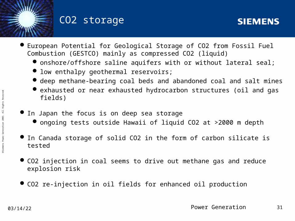
CO2 storage
European Potential for Geological Storage of CO2 from Fossil Fuel Combustion (GESTCO) mainly as compressed CO2 (liquid)
onshore/offshore saline aquifers with or without lateral seal; low enthalpy geothermal reservoirs; deep methane-bearing coal beds and abandoned coal and salt mines exhausted or near exhausted hydrocarbon structures (oil and gas fields)
In Japan the focus is on deep sea storage ongoing tests outside Hawaii of liquid CO2 at >2000 m depth
In Canada storage of solid CO2 in the form of carbon silicate is tested
CO2 injection in coal seems to drive out methane gas and reduce explosion risk
CO2 re-injection in oil fields for enhanced oil production

Power Generation 32
S
iem
ens
Pow
er G
ener
atio
n 20
03.
All
Rig
hts
Res
erve
d
04/18/23
CO2 storage in North Sea oil well

Power Generation 33
S
iem
ens
Pow
er G
ener
atio
n 20
03.
All
Rig
hts
Res
erve
d
04/18/23
The Canadian process for solidification of CO2
Anaerobic gasification of coal to H2 and CO2 Combustion of H2 in Solid Oxide Fuel Cell Solidification of CO2 to calcium carbonate with lime Recovery of lime and release of pure CO2 using waste heat from the
SOFC Formation of magnesium carbonate from magnesium silicate Magnesium carbonate is stable and will be stored in the magnesium
silicate mines
Power Generation 34
S
iem
ens
Pow
er G
ener
atio
n 20
03.
All
Rig
hts
Res
erve
d
04/18/23
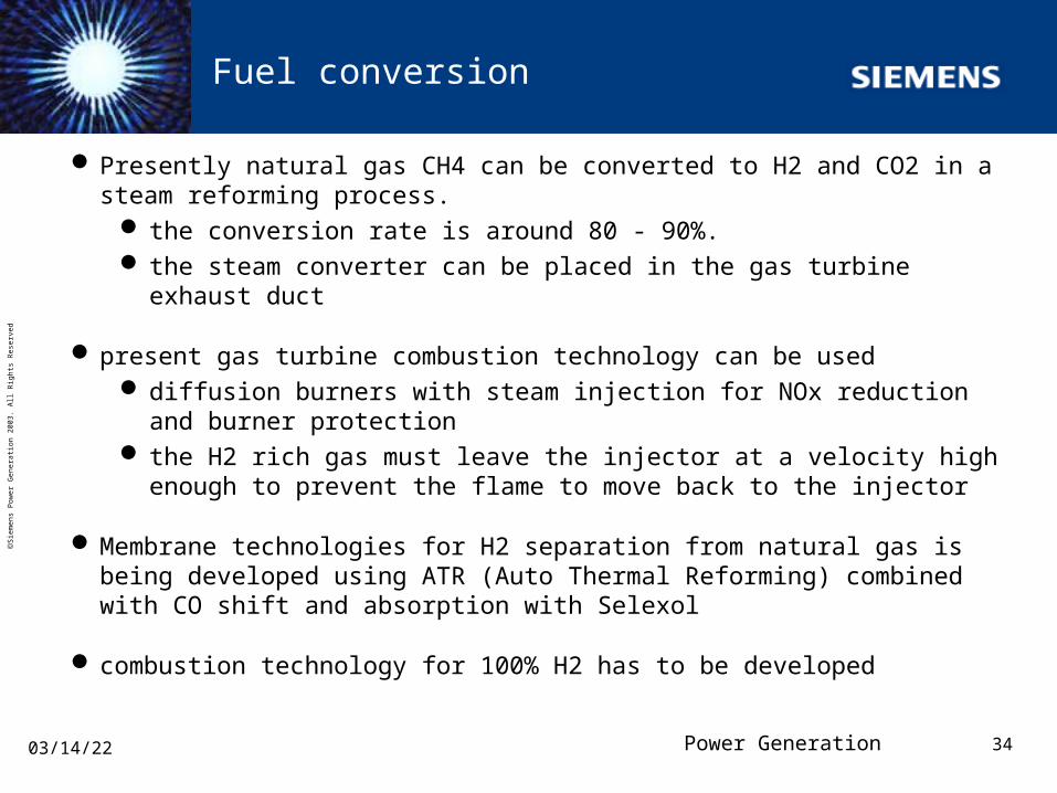
Fuel conversion
Presently natural gas CH4 can be converted to H2 and CO2 in a steam reforming process.
the conversion rate is around 80 - 90%. the steam converter can be placed in the gas turbine exhaust duct
present gas turbine combustion technology can be used diffusion burners with steam injection for NOx reduction and burner
protection the H2 rich gas must leave the injector at a velocity high enough to
prevent the flame to move back to the injector
Membrane technologies for H2 separation from natural gas is being developed using ATR (Auto Thermal Reforming) combined with CO shift and absorption with Selexol
combustion technology for 100% H2 has to be developed

Power Generation 35
S
iem
ens
Pow
er G
ener
atio
n 20
03.
All
Rig
hts
Res
erve
d
04/18/23
Oxy-combustion
Combustion of a fuel, hydrocarbon or pure H2 with Oxygen, O2, without the presence or air is called Oxy-combustion
Several project ongoing to develop combustion technology for combustion in
inert gases, such as Steam CO2
Fuel
CombustorAirintake
Air separationplant
Turbine
CO2 to storage CO2
compression
Oxygen
RecuperatorCoolingwater
Excesswater
H2O
Condenser

Power Generation 36
S
iem
ens
Pow
er G
ener
atio
n 20
03.
All
Rig
hts
Res
erve
d
04/18/23
Coal conversion
Coal will be burnt as today in large steam plants, but with CO2 sequestration
Coal gasification Combi Cycles are built today addition of CO2 recovery processes are now being developed
Coal gas (the gas stored in the coal pits) will be used more frequently for reducing risk of explosions reducing need for ventilation
Coal gasification underground is being developed in Russia a gas similar to coke oven gas (Hydrogen rich) is produced for use in
combined cycles for power productionin processes for liquid fuel production, with the rest product (lean gas)
used in the combi cycle

Power Generation 37
S
iem
ens
Pow
er G
ener
atio
n 20
03.
All
Rig
hts
Res
erve
d
04/18/23
CO2 injection in coal seams
Coal Bed Methane, CBM, is always leaking more or less from coal seams, going into the atmosphere. It is also causing high explosion risks at mining
Injection of CO2 in the coal beds is now tested to drive out the methane in a controlled way burn it in gas turbines recover the CO2 re-inject the CO2
Most of these processes require a catalytic process to produce H2 and CO from the fuel gas
The H2 and CO can then be burnt in inert atmosphere or converted to a liquid fuel in another catalytic process

Power Generation 38
S
iem
ens
Pow
er G
ener
atio
n 20
03.
All
Rig
hts
Res
erve
d
04/18/23
CO2 absorption
The CO2 in combustion gas is absorbed in an amine solution which can be re-generated. The amine solution is volatile and there is quite a large consumption in atmospheric reactors. The amines are not fully environmentally acceptable
atmospheric absorption processes are developed for exhaust gas from natural gas fired gas turbines and coal boilers. The CO2 concentration is low and the plants large, since they have to handle big volume flows
pressurised absorption has been suggested but so far not tested. There are advantages
the flow volumes are smaller the CO2 partial pressure higher the volatility of the amines is reduced and the losses smaller
It is claimed that all components for the absorption systems are available on the market

Power Generation 39
S
iem
ens
Pow
er G
ener
atio
n 20
03.
All
Rig
hts
Res
erve
d
04/18/23
Pressurised CO2 absorption
Two cycles have been suggested absorption reactor after the combustor at highest pressure and
temperature absorption reactor in between turbines at lower pressure and
temperature
The absorption process generally reduces a combined plant efficiency by more than 10% mainly due to pressure losses
a special cycle similar to the PFBC cycle, but with gas fired combustor would have lower initial efficiency, but will have less influence of the absorption system
in order to further reduce the absorption system gas turbines are used in series

Power Generation 40
S
iem
ens
Pow
er G
ener
atio
n 20
03.
All
Rig
hts
Res
erve
d
04/18/23
Pressurised CO2 absorption system
The P-type gas turbine has a pressurised gas fired steam generator of the same basic design as a PFBC. The exhaust gas is cooled down to ~ 100°C before going in to the CO2 absorption vessel. The gas is then reheated before going to the turbine. NOx is hopefully washed out in the cooling process.
Name of Event
Heat exchangers
Pressurised steam generator
Pressurised amino scrubber
CO2
To High Pressure Turbine 850 C
From High Pressure Compressor To steam
turbine
950 C

Power Generation 41
S
iem
ens
Pow
er G
ener
atio
n 20
03.
All
Rig
hts
Res
erve
d
04/18/23
17MW GT35P and 70 MW GT140P
Flexible gas turbines, adjustable for LBTU gases, with silo type of LBTU combustor

Power Generation 42
S
iem
ens
Pow
er G
ener
atio
n 20
03.
All
Rig
hts
Res
erve
d
04/18/23
500 MW Plant configuration with CO2 concentration
GTX100 HRSG Scrubber
Nock out pot
GT140P
CO2
#1 step #3 step #4 step

Power Generation 43
S
iem
ens
Pow
er G
ener
atio
n 20
03.
All
Rig
hts
Res
erve
d
04/18/23
Combi cycle with high pressure CO2 absorption using amine solution
3
1
24
5
67
8
92
Compression of CO2
Steamturbine
HRSGCondenser
To stack
Fuel
Compressor
Exhaust
Airintake
Turbine
CO2
CO2
Gas turbine
Steambleed
Steam
Absorption of CO2 at pressure
after the combustor
in between turbines
favourable due to higher CO2 partial pressure
and atmospherically
after the turbine only 3% CO2
Loss in efficiency >10%
The use of two gas turbines in series to increase CO2 concentration

Power Generation 44
S
iem
ens
Pow
er G
ener
atio
n 20
03.
All
Rig
hts
Res
erve
d
04/18/23
CO2 turbines
Several cycles have been proposed using closed loop CO2 turbines
Unfortunately a standard gas turbine will not work due to the difference in density and specific heat cp from air
more stages in turbine and compressor
Proposals for running the closed loop at high pressure to reduce the plant size has been presented

Power Generation 45
S
iem
ens
Pow
er G
ener
atio
n 20
03.
All
Rig
hts
Res
erve
d
04/18/23
Plants for O2 production and power plants with integrated O2 production
Oxygen production using Mixed Conducting Membranes are being developed. Oxygen will be needed for many gasification processes
In order to reduce size of the plants and especially the reactor, the plants are pressurised by integrating a gas turbine.
The next step is to use the same technology for power production
The critical element is the Mixed Conducting Membrane itself and the reactor built on it

Power Generation 46
S
iem
ens
Pow
er G
ener
atio
n 20
03.
All
Rig
hts
Res
erve
d
04/18/23
Membrane Transport Processes
Generally, gas-selective membranes are based on porous membranes that use the molecular size to separate gas components in a mixture, e.g. Knudsen flow or molecular sieving
Dense membranes (ceramic or metal) transport atoms or ions selectively through the membrane
Dense oxygen selective membranes transport both oxygen ions and electrons, i.e. mixed conductivity
Driving force gives that pO2, permeate < pO2, retentate
Sweep gas Sweep gas + O2
N2 + less O2 N2+ O2 (usually air)
Dense ceramicmixed conductivemembrane
O2-e -
pO2, permeate
pO2, retentate

Power Generation 47
S
iem
ens
Pow
er G
ener
atio
n 20
03.
All
Rig
hts
Res
erve
d
04/18/23
Oxygen flux (permeability) is a function of:
Membrane material
Temperature (Arrhenius-type behavior)
Membrane thickness/thinness
Potential Pressure gradient (pO2)
Reported from others are:
Balachandran: O2 permeability 2.5 cc cm-2 min -1,
that is 36 kg O2 m-2 per day
Norsk Hydro: 200 kg O2 m-2 day-1
Power Generation 48
S
iem
ens
Pow
er G
ener
atio
n 20
03.
All
Rig
hts
Res
erve
d
04/18/23
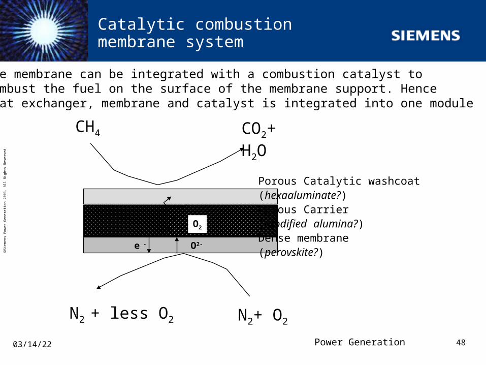
Catalytic combustion membrane system
CH4 CO2+ H2O
N2 + less O2 N2+ O2
O2
Porous Catalytic washcoat (hexaaluminate?)Porous Carrier (modified alumina?)Dense membrane (perovskite?)
O2-e -
The membrane can be integrated with a combustion catalyst tocombust the fuel on the surface of the membrane support. Henceheat exchanger, membrane and catalyst is integrated into one module

Power Generation 49
S
iem
ens
Pow
er G
ener
atio
n 20
03.
All
Rig
hts
Res
erve
d
04/18/23
Membrane materials I - mixed ion/electron conductors
Various membrane structuresa) thin dense membrane layer on porous substrateb) porous substrate plugged with dense membrane particlesc) thin dense membrane with increased surface area
A B C
Dense membrane
Porous support

Power Generation 50
S
iem
ens
Pow
er G
ener
atio
n 20
03.
All
Rig
hts
Res
erve
d
04/18/23
Early MCM Combustion System
H2O,CO2,O2
Pre-combustor
Preheater
Membrane
After burner
CH4
Compressor Air
H2
Turbine Inlet

Power Generation 51
S
iem
ens
Pow
er G
ener
atio
n 20
03.
All
Rig
hts
Res
erve
d
04/18/23
CombustorCH4
Membrane
CH4
Steam TurbineBoiler
Gas Turbine
Compressor
Early MCM Power Plant
HEX Condenser
CO2
850 C/12 bar
420 C
Combustor
Air Preheater
Power Plant Efficiency 37%

Power Generation 52
S
iem
ens
Pow
er G
ener
atio
n 20
03.
All
Rig
hts
Res
erve
d
04/18/23
Start Combustor
CH4
MembraneReactor
CH4
Steam Turbine
Boiler
Gas Turbine
To Steam turbine
Intermediate MCM Power Plant
450 C 20 bar
CO2
CO2+H20
Steam
Air Preheater
550 C
1200 C/14 barSteam Injection
Combine Cycle Efficiency 47 %
Water injection

Power Generation 53
S
iem
ens
Pow
er G
ener
atio
n 20
03.
All
Rig
hts
Res
erve
d
04/18/23
Start Combustor
CH4
MembraneReactor
CH4
Steam Expander
Boiler
Gas Turbine
To Steam turbine
Final MCM Power Plant
1200 C 20 bar
CO2
CO2+H20
Steam
Air Preheater
550 C
1200 C/14 barSteam Injection
Combine Cycle Efficiency 55 %

Power Generation 54
S
iem
ens
Pow
er G
ener
atio
n 20
03.
All
Rig
hts
Res
erve
d
04/18/23
Chemical looping basics

Power Generation 55
S
iem
ens
Pow
er G
ener
atio
n 20
03.
All
Rig
hts
Res
erve
d
04/18/23
Chemical looping with fluid beds

Power Generation 56
S
iem
ens
Pow
er G
ener
atio
n 20
03.
All
Rig
hts
Res
erve
d
04/18/23
Fuel Cell
The Solid Oxide Fuel Cell is very similar to the Mixed Conducting Membrane.
In MCM the ion/electron transport is Short circuited
in the SOFC membrane there is electrical leads on the membrane to use the electron transport
in the fuel cell power plant around 60 - 80% of the electric power will be produced in the membrane and the rest from the turbines. The gas turbine will be small and is there mainly to pressurise the system and circulate the medium.
the development of Solid Oxide fuel cells has gone on for years, but without a break through. Siemens is one of the few players.

Power Generation 57
S
iem
ens
Pow
er G
ener
atio
n 20
03.
All
Rig
hts
Res
erve
d
04/18/23
Conclusions
The power production cycles for the future will have gas and/or steam turbines integrated in the processes
There will be a number of gas turbine applications for low heating value gases bio mass gasification off gases from chemical processes and steel industry
for which special combustion systems must be developed lean premixed systemscatalytic systems
CO2 sequestration will be applied to all power production independent on fuel origin (fossil or bio mass)
processes with membranes will probably be the best but absorption type of clean up systems are closer to realisation

Power Generation 58
S
iem
ens
Pow
er G
ener
atio
n 20
03.
All
Rig
hts
Res
erve
d
04/18/23
Please address all correspondence to:
Siemens Industrial Turbomachinery ABSE-612 83 FINSPONG
© Siemens Industrial Turbomachinery ABNo part of this document may be reproduced or transmitted in any form or by any means, including photocopying and recording without the written permission of Siemens Industrial Turbomachinery AB