research article a bridge deflection monitoring system...
TRANSCRIPT
Research ArticleA Bridge Deflection Monitoring System Based on CCD
Baohua Shan12 Lei Wang3 Xiaoyang Huo2 Wenting Yuan2 and Zhilin Xue2
1Key Lab of Structures Dynamic Behavior and Control (Harbin Institute of Technology) Ministry of Education Harbin 150090 China2School of Civil Engineering Harbin Institute of Technology Harbin 150090 China3School of Civil Engineering and Architecture University of Jinan Jinan 250022 China
Correspondence should be addressed to Baohua Shan shanbaohuahiteducn
Received 9 June 2016 Revised 6 September 2016 Accepted 21 September 2016
Academic Editor Ying Wang
Copyright copy 2016 Baohua Shan et al This is an open access article distributed under the Creative Commons Attribution Licensewhich permits unrestricted use distribution and reproduction in any medium provided the original work is properly cited
For long-term monitoring of the midspan deflection of Songjiazhuang cloverleaf junction on 309 national roads in Zibo citythis paper proposes Zhangrsquos calibration-based DIC deflection monitoring method CCD cameras are used to track the changeof targetsrsquo position Zhangrsquos calibration algorithm is introduced to acquire the intrinsic and extrinsic parameters of CCD camerasand the DIC method is combined with Zhangrsquos calibration algorithm to measure bridge deflection The comparative test betweenZhangrsquos calibration and scale calibration is conducted in lab and experimental results indicate that the proposedmethod has higherprecision According to the deflectionmonitoring scheme the deflectionmonitoring software for Songjiazhuang cloverleaf junctionis developed byMATLAB and a 4-channel CCDdeflectionmonitoring system for Songjiazhuang cloverleaf junction is integrated inthis paperThis deflectionmonitoring system includes functions such as image preview simultaneous collection camera calibrationdeflection display and data storage In situ deflection curves show a consistent trend this suggests that the proposed method isreliable and is suitable for the long-term monitoring of bridge deflection
1 Introduction
It is very significant that monitoring bridge deflection canevaluate the health status of bridge and can provide theimportant reference base for the structural performanceand operational status of bridge Currently there are twokinds of deflection measurement methods which are thetraditional measurement method and the automatic mea-surement method The traditional measurement methodsinclude dial indicator level and total station The principleof dial indicator measuring bridge deflection is very simple[1] However due to the great height of bridge it is veryinconvenient to install the dial indicator on main girder ofbridge The level is usually used to measure bridge deflectionalong with a scale [2] and this increases the complexity ofmeasurement work Furthermore the total station is easilyinfluenced by temperature and humidity and is not suitablefor long-term monitoring in the wild [3] In a word thetraditional measurement methods are rarely used to execute
the long-termmonitoring of bridge deflection except for thetemporary measurement
The automatic measurement methods comprise accel-erometer microwave interferometer GPS connected pipeoptoelectronic liquid level sensor and so forth The high-frequency component occupies a large proportion in the datacollected by accelerometer so the low-frequency componentis drowned out when the displacement is obtained by com-puting the integral for acceleration data However the bridgedeflection is exactly the low-frequency component In themeantime the double integral brings about errors As a resultthe accelerometer has lower precision [4] The microwaveinterferometer can detect the bridge deflection accordingto the phase difference of reflected wave before and afterdeformation Although the microwave interferometer hashigher precision this method is not suitable for the case thatthe transverse deformation and longitudinal deformationsimultaneously occur on bridge [5] GPS has very goodpracticability Nevertheless the cost of GPS is higher and the
Hindawi Publishing CorporationAdvances in Materials Science and EngineeringVolume 2016 Article ID 4857373 11 pageshttpdxdoiorg10115520164857373
2 Advances in Materials Science and Engineering
z
x
y
u
v
P
O
Camera center Image plane
o
Xw
Yw
Zw
(u0 0)Id
Iu
R T
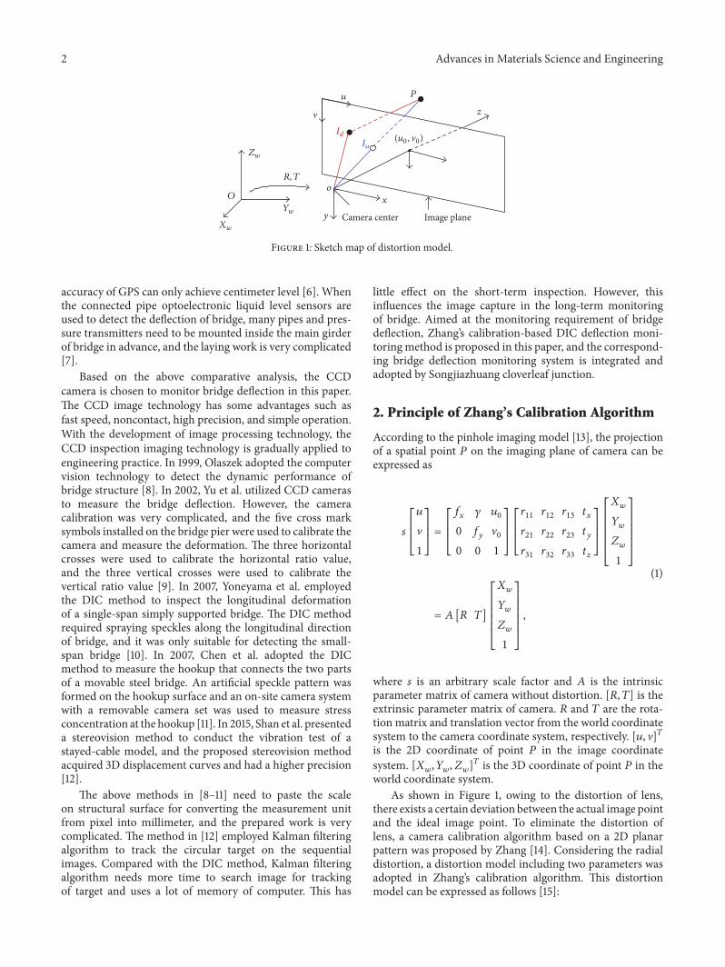
Figure 1 Sketch map of distortion model
accuracy of GPS can only achieve centimeter level [6] Whenthe connected pipe optoelectronic liquid level sensors areused to detect the deflection of bridge many pipes and pres-sure transmitters need to be mounted inside the main girderof bridge in advance and the laying work is very complicated[7]
Based on the above comparative analysis the CCDcamera is chosen to monitor bridge deflection in this paperThe CCD image technology has some advantages such asfast speed noncontact high precision and simple operationWith the development of image processing technology theCCD inspection imaging technology is gradually applied toengineering practice In 1999 Olaszek adopted the computervision technology to detect the dynamic performance ofbridge structure [8] In 2002 Yu et al utilized CCD camerasto measure the bridge deflection However the cameracalibration was very complicated and the five cross marksymbols installed on the bridge pier were used to calibrate thecamera and measure the deformation The three horizontalcrosses were used to calibrate the horizontal ratio valueand the three vertical crosses were used to calibrate thevertical ratio value [9] In 2007 Yoneyama et al employedthe DIC method to inspect the longitudinal deformationof a single-span simply supported bridge The DIC methodrequired spraying speckles along the longitudinal directionof bridge and it was only suitable for detecting the small-span bridge [10] In 2007 Chen et al adopted the DICmethod to measure the hookup that connects the two partsof a movable steel bridge An artificial speckle pattern wasformed on the hookup surface and an on-site camera systemwith a removable camera set was used to measure stressconcentration at the hookup [11] In 2015 Shan et al presenteda stereovision method to conduct the vibration test of astayed-cable model and the proposed stereovision methodacquired 3D displacement curves and had a higher precision[12]
The above methods in [8ndash11] need to paste the scaleon structural surface for converting the measurement unitfrom pixel into millimeter and the prepared work is verycomplicated The method in [12] employed Kalman filteringalgorithm to track the circular target on the sequentialimages Compared with the DIC method Kalman filteringalgorithm needs more time to search image for trackingof target and uses a lot of memory of computer This has
little effect on the short-term inspection However thisinfluences the image capture in the long-term monitoringof bridge Aimed at the monitoring requirement of bridgedeflection Zhangrsquos calibration-based DIC deflection moni-toring method is proposed in this paper and the correspond-ing bridge deflection monitoring system is integrated andadopted by Songjiazhuang cloverleaf junction
2 Principle of Zhangrsquos Calibration Algorithm
According to the pinhole imaging model [13] the projectionof a spatial point 119875 on the imaging plane of camera can beexpressed as
119904 [[[119906V1]]] = [[[
119891119909 120574 11990600 119891119910 V00 0 1]]][[[11990311 11990312 11990313 11990511990911990321 11990322 11990323 11990511991011990331 11990332 11990333 119905119911
]]][[[[[[
1198831199081198841199081198851199081]]]]]]
= 119860 [119877 119879][[[[[[
1198831199081198841199081198851199081]]]]]]
(1)
where 119904 is an arbitrary scale factor and 119860 is the intrinsicparameter matrix of camera without distortion [119877 119879] is theextrinsic parameter matrix of camera 119877 and 119879 are the rota-tion matrix and translation vector from the world coordinatesystem to the camera coordinate system respectively [119906 V]119879is the 2D coordinate of point 119875 in the image coordinatesystem [119883119908 119884119908 119885119908]119879 is the 3D coordinate of point 119875 in theworld coordinate system
As shown in Figure 1 owing to the distortion of lensthere exists a certain deviation between the actual image pointand the ideal image point To eliminate the distortion oflens a camera calibration algorithm based on a 2D planarpattern was proposed by Zhang [14] Considering the radialdistortion a distortion model including two parameters wasadopted in Zhangrsquos calibration algorithm This distortionmodel can be expressed as follows [15]
Advances in Materials Science and Engineering 3
119883119889 = 119883119906 + 11989611198831199061199032 + 11989621198831199061199034119884119889 = 119884119906 + 11989611198841199061199032 + 11989621198841199061199034 (2)
where 119903 = radic1198832119906 + 1198842119906 and (119883119889 119884119889) is the normalizedcoordinate of image point under distorted condition (119883119906 119884119906)is the normalized coordinate of image point under undis-torted condition Both 1198961 and 1198962 are the radial distortionscoefficients The matrix 119860 in (1) and 1198961 1198962 are collectivelycalled the intrinsic parameters of camera
Zhangrsquos calibration algorithm only requires the camera toobserve a planar pattern shown at a few (at least two) differentorientations Either the camera or the planar pattern can befreely moved The motion need not be known The detailedcalibration procedure of Zhangrsquos algorithm is given asbelow
21 Solving the Intrinsic and Extrinsic Parameters of Cam-era As seen from (1) there exists the projective trans-formation relation between the world coordinate systemand the image coordinate system Suppose that the 2Dplanar pattern is selected as the model plane of the worldcoordinate system namely 119885119908 = 0 Let us denote the119894th column of the rotation matrix 119877 by 119903119894 From (1) wehave
119904 [[[119906V1]]] = 119860 [1199031 1199032 1199033 119905] [[[[[[
11988311990811988411990801]]]]]]
= 119860 [1199031 1199032 119905] [[[1198831199081198841199081
]]] (3)
Let = [119906 V 1]119879 and = [119883119908 119884119908 1] we have119904 = 119867 (4)
where 119867 = 120582119860 [1199031 1199032 119905] = [ℎ1 ℎ2 ℎ3] where 120582 is anarbitrary scalar
Computing 119867 is a process that solves the minimumresidual error between the actual image coordinate119898119894 and theimage coordinate 119894 which is calculated by (4) the objectivefunction is minsum119894 119898119894 minus 119894(119867)2
After solving 119867 two basic constraints on the intrinsicparameters119860 are obtained according to the orthogonality andgiven as follows
ℎ1198791119860minus119879119860minus1ℎ2 = 0ℎ1198791119860minus119879119860minus1ℎ1 = ℎ1198792119860minus119879119860minus1ℎ2 (5)
Let
119861 = 119860minus119879119860minus1 = [[[11986111 11986112 1198611311986121 11986122 1198612311986131 11986132 11986133
]]] =[[[[[[[[[[[
1119891119909 minus 1199031198912119909119891119910 V0120574 minus 11990601198911199101198912119909119891119910minus 1199031198912119909119891119910 120574211989121199091198912119910 + 11198912119910 minus120574 (V0120574 minus 1199060119891119910)11989121199091198912119910 minus V01198912119910V0120574 minus 11990601198911199101198912119909119891119910 minus120574 (V0120574 minus 1199060119891119910)11989121199091198912119910 minus V01198912119910 (V0120574 minus 1199060119891119910)211989121199091198912119910 + V201198912119910 + 1
]]]]]]]]]]] (6)
Note that 119861 is symmetric defined by a 6D vector 119887 =[11986111 11986112 11986122 11986113 11986123 11986133]119879Let the 119894th column vector of119867 be ℎ119894 = [ℎ1198941 ℎ1198942 ℎ1198943]119879 then
we have
ℎ119879119894 119861ℎ119895 = V119879119894119895119887 (7)
with V119894119895 = [ℎ1198941ℎ1198951 ℎ1198942ℎ1198951+ℎ1198941ℎ1198952 ℎ1198942ℎ1198952 ℎ1198943ℎ1198951+ℎ1198941ℎ1198953 ℎ1198943ℎ1198952+ℎ1198942ℎ1198953 ℎ1198943ℎ1198953]119879Therefore (5) can be expressed by the following equation
[ V11987912V11 minus V22
] 119887 = 0 (8)
If 119899 images of the model plane are observed by stacking119899 such equations as (8) we have
119881119887 = 0 (9)
where 119881 is a 2119899 times 6matrix If 119899 gt 3 we will have in general aunique solution 119887 defined up to a scale factor
Once 119887 is estimated we can compute all camera intrinsicparametersThematrix119861 is estimated up to a scale factor thatis 119861 = 120582119860minus119879119860minus1 with 120582 being an arbitrary scale Withoutdifficulty we can uniquely extract the intrinsic parametersfrom matrix 119861 Once 119860 is known the extrinsic parametersfor each image are readily computed From (4) we have
1199031 = 120582119860minus1ℎ11199032 = 120582119860minus1ℎ2
4 Advances in Materials Science and Engineering
1199033 = 1199031 times 1199032119905 = 120582119860minus1ℎ3
(10)
where 120582 = 1119860minus1ℎ1 = 1119860minus1ℎ222 Maximum-Likelihood Estimation In general case thedistortion of lens cannot be ignoredTherefore in the secondstep the intrinsic and extrinsic parameters derived in the firststep are regarded as the initial values to execute optimization
We are given 119899 images of a 2D planar plane and there are119898 points on the planar plane Assume that the image pointsare corrupted by independent and identically distributednoise For different point on a planar plane the initial valuesof distortion coefficients 1198961 1198962 can be solved from (2) by theleast square method The detailed process can refer to thetechnical report [16]
These initial values including the intrinsic and extrinsicparameters and the distortion coefficients are substituted intothe objective function to optimize camera The maximum-likelihood estimate can be obtained by minimizing thefollowing function
119899sum119894=1
119898sum119895=1
10038171003817100381710038171003817119898119894119895 minus (119860 1198961 1198962 119877119894 119879119894119872119895)100381710038171003817100381710038172 (11)
where (119860 1198961 1198962 119877119894 119879119894119872119895) is the projection of point119872119895 inimage 119894 according to (4)
Minimizing (11) is a nonlinear minimization problemwhich is solved with the Levenberg-Marquardt algorithm[17] It requires an initial guess of 119860 [119877119894 119905119894] (119894 = 1 119899)which can be obtained using the technique described in theprevious section
Through the above two steps the intrinsic and extrinsicparameters including nonlinear distortion coefficients ofcamera are all achieved
3 Zhangrsquos Calibration-Based DIC DeflectionMonitoring Method
The DIC method is widely used to measure the surfacedisplacement or strain according to the correlation of lightintensity of speckles before and after deformation which aredistributed on specimen surface randomly [18] When theDIC method is employed to detect deformation a singleCCD camera is usually required to be perpendicular to themeasured surface and the angle between the optical axis ofCCD camera and the vertical line ofmeasured surface cannotbe larger than 5∘ [18] In engineering the angle between theoptical axis of CCD camera and the vertical line of measuredsurface is often larger than 5∘ As a result the DIC methodcannot be directly used to measure deformation when theskew angle is larger than 5∘ To deal with this problemZhangrsquos calibration algorithm is introduced to figure outstrict limit of the skew angle of CCD camera FurthermoreZhangrsquos calibration algorithm can eliminate lens distortionand convert measurement unit
31 Principle of DIC The correlation criterion needs to befirstly confirmed when the DIC method is used to calculatedeformation The zero-mean normalized cross-correlation(ZNCC) criterion has the most robust noise-proof perfor-mance and is insensitive to the linear scale and offset inlighting on images Considering the requirement of actualapplication the ZNCC criterion is chosen to conduct areamatching in this paperTheZNCCcriterion is given as follows[19]
119862ZNCC = sum119872119909=minus119872sum119872119910=minus119872 [119891 (119909 119910) minus 119891] sdot [119892 (119909lowast 119910lowast) minus 119892]radicsum119872119909=minus119872sum119872119910=minus119872 [119891 (119909 119910) minus 119891]2 sdot radicsum119872119909=minus119872sum119872119910=minus119872 [119892 (119909lowast 119910lowast) minus 119892]2 (12)
where 119891(119909 119910) is the gray value of reference image subset119892(119909lowast 119910lowast) is the gray value of target image subset and119891 119892 arethe mean gray of reference image subset and target image
The conics fitting method is used to conduct subpixelsearch in this paper Assume that the pixel position of a pointwhose absolute value is the largest in thematrix of correlationcriterion 119862ZNCC is 119876(1199090 1199100) Total nine points composed ofpoint 119876 and its eight nearest-neighbor points can locallyconstitute the quadratic surface and the surface equation isgiven as below
Φ(119909 119910) = 1198861199092 + 1198871199102 + 119888119909119910 + 119889119909 + 119890119910 + 119891 (13)
Utilizing the pixel positions of nine points and the cor-relation coefficients of corresponding positions the values of119886 sim 119891 in (13) can be solved and the extreme point coordinates
of surface can be obtained that is ((119888119890minus2119887119889)(4119886119887minus1198882) (119888119889minus2119886119890)(4119886119887 minus 1198882)) This extreme point is exactly the centerof subset on the deformed image the center coordinatersquosdifference between the reference image and the deformedimage is just the displacement of point119876 whose unit is pixel
Before test the traditional DIC method needs to pastethe scale whose length is known on the measured surfacefor converting measurement unit from pixel into millimeterIn most cases the scale may be the coordinate paper with acertain length or the geometry size of specimen Accordingto the ratio of the actual length of scale to the pixel lengthon image the traditional DIC method can convert themeasurement unit of displacement frompixel intomillimeter
32 Displacement Calculation of Measured Point As shownin Figure 1 suppose that the coordinate of point 119875 in the
Advances in Materials Science and Engineering 5
world coordinate system 119874 minus 119883119908119884119908119885119908 is (119883119908 119884119908 119885119908)119879 andits coordinate in the camera system 119900 minus 119909119910119911 is (119909 119910 119911)119879In the image coordinate system the homogeneous imagecoordinate in millimeters is (119883 119884 1)119879 and the homogeneousimage coordinate in pixels is (119906 V 1)119879 After subpixel searchof DIC (119906 V 1)119879 has been given As a result the relationbetween (119883 119884 1)119879 and (119906 V 1)119879 can be described as follows[20]
(1198831198841) = [[[119889119883 0 minus1199060 times 1198891198830 119889119884 minusV0 times 1198891198840 0 1
]]](119906V1) (14)
where 119889119883 and 119889119884 are the physical size of a pixel on 119909-axis and119910-axis respectively in mmpixel and these two parametersare the intrinsic parameters (1199060 V0)119879 is the coordinate ofprincipal point in pixels
The relation between the coordinate (119909 119910 119911)119879 in thecamera coordinate system and the homogeneous imagecoordinate in millimeters (119883 119884 1)119879 is expressed as below
(119909119910119911) = [[[[[119904119891 0 00 119904119891 00 0 119904
]]]]](1198831198841) (15)
where 119891 is the focal length and 119904 is the scale factorThe coordinate (119883119908 119884119908 119885119908)119879 in the world coordinate
system and the coordinate (119909 119910 119911)119879 in the camera systemmeet the following equation
(119883119908119884119908119885119908) = 119877minus1((119909119910119911) minus 119879) (16)
where 119877 is the rotation matrix from the camera system intothe world coordinate system and 119879 is the translation matrixfrom the camera system into the world coordinate system119877 119879 can be acquired by Zhangrsquos calibration algorithm
Equation (14) is substituted into (15) and (17) is given asbelow
(119909119910119911) = 119904119891 [[[119889119883 0 minus1199060 times 1198891198830 119889119884 minusV0 times 1198891198840 0 119891
]]](119906V1) (17)
Combining (16) and (17) the coordinate (119883119908 119884119908 119885119908)119879 inthe world coordinate can be solved from the homogeneousimage coordinate in pixels (119906 V 1)119879
In (17) the scale factor 119904 must be obtained firstly Thevalue of 119904 is related with the selection of world coordinatesystem In this paper the world coordinate system is estab-lished on the measured surfaceThe plane119883119908119884119908 of the worldcoordinate system coincides with the measured surface and119885119908 axis conforms to the right-handed coordinate systemAnythree points in the word coordinate system are selected to
establish the plane equation and the equation is described asfollows 119860119909 + 119861119910 + 119862119911 + 119863 = 0 (18)
where 119860 119861 119862 119863 are the coefficients of plane equationEquation (17) can also be expressed by the equation set as
follows
119909 = 119904 (119906 minus 1199060) 119889119883119891 119910 = 119904 (V minus V0) 119889119884119891 119911 = 119904
(19)
Equation (19) is substituted into (18) 119904 can be given by thefollowing equation
119904 = minus119863119860 (119906 minus 1199060) (119889119883119891) + 119861 (V minus V0) (119889119884119891) + 119862 (20)
Through the above calculation the homogeneous imagecoordinate (119906 V 1)119879 in pixels can be converted to the coor-dinate (119883119908 119884119908 119885119908)119879 in millimeters in the world coordinatesystem Therefore this paper implements the conversion ofmeasurement unit from millimeters into pixels by Zhangrsquoscalibration algorithm
The sketch map of target image acquired by each CCDcamera is shown in Figure 2 The solid circle surroundedby a rectangle is exactly white spot in Figure 2 which isthe target tracked by each CCD camera The rectangle inFigure 2 is the matching subset extracted by DIC methodwhich is used for calculating deformation Assume that theimage coordinate of matching subsetrsquos center at 1199050 is (1199090 1199100)Deformations are found on bridge under load and theimage coordinate of matching subsetrsquos center at 119905119894 is (119909119894 119910119894)Thereby the displacement of measured point on bridge at119905119894 can be obtained by subtracting two coordinates and thedisplacement equation is given by
Δ119909 = 119909119894 minus 1199090Δ119910 = 119910119894 minus 1199100 (21)
where Δ119909 is the transverse displacement of measured pointon bridge at 119905119894 and Δ119910 is the vertical displacement ofmeasured point on bridge at 119905119894 which is exactly the bridgedeflection in pixels
Through the above conversion of measurement unit thebridge deflection in millimeters can be acquired accordingly
4 Comparative Test of Calibration Algorithms
To testify effectiveness and feasibility of Zhangrsquos calibration-based DIC deflection monitoring method proposed in thispaper the comparative test of two calibration methods isconducted in lab One is Zhangrsquos calibration algorithm andthe other is the scale calibration adopted by traditional DICmethod
6 Advances in Materials Science and Engineering
x
y
Matchingsubset
o
y0
x0
(a)
x
y
o
yi
xi
Matchingsubset
(b)
Figure 2 Schematic of change of targetrsquos position (a) initial stage (b) deformation stage
Mobile platform
Translation knob
Specimen
Dial gauge
Figure 3 Experimental photo
41 Experimental Setup As illustrated in Figure 3 the speci-men is 300mm in length and 50mm in width The specimensurface is coated with white paint and some silicon carbidessprayed randomly on white paint are regarded as specklesThe specimen is fixed on the mobile platform the translationknob in Figure 3 can control the horizontal movement ofspecimen and the moving range from left to right is 20mm
To compare with the detection results of the proposedmethod in this paper the dial gauge is pressed againstthe measured specimen The measurement range of dialgauge is 25mm and the precision is 0001mm The mea-sured specimen moved horizontally along with the mobileplatform each movement distance is about 1mm In testthe dial gauge read is recorded and the specimen image issimultaneously captured by CCD camera along with eachrotation of translation knob The CCD camera is placed 1maway from the specimen The cameras can record the high-definition images with a pixel resolution of 1280times 960 at 1 fpsThe CCD camera is equipped with an optical zoom lens ofF18ndash16 and focal length ranging between 12 and 36mm
During test both Zhangrsquos calibration algorithm and scalecalibration are adopted to convert the measurement unit ofhorizontal displacement in this paper The scale selected bythe traditional DIC method is the actual length of specimenwhich is 300mm and the corresponding length in image is64793 pixels Therefore the scale factor between actual sizeand pixel size is 04630mmpixel and this value is exactlythe conversion coefficient of measurement unit used by thetraditional DIC method
O
9 times 30mm
9times30
mmX
Y
Figure 4 Planar pattern
As shown in Figure 4 a planar pattern consisting ofeighty-one 30mmtimes 30mmblack andwhite squares is used tocalibrate CCD camera The open software ldquoCamera Calibra-tionToolbox forMATLABrdquo [21] which is compiled accordingto Zhangrsquos algorithm based on a planar pattern is employedto execute the camera calibration in this paper Before test 9images of the planar pattern in different postures are firstlycaptured by the CCD camera for camera calibration Then8 times 8 corner points on each image which are expressed bythe red rectangle in Figure 4 are selected to execute cameracalibration by the calibration software Finally the intrinsicand extrinsic parameters including nonlinear distortion coef-ficients of CCD camera are all obtained by the calibrationsoftware
42 Experimental Result Analysis The displacement curvesacquired by two different calibration algorithms are shown inFigure 5 It can be seen that two displacement curves havethe same trend and agree very well The displacement dataobtained by dial gauge are regarded as the truth-value ofdisplacement in this paper and the displacement errors of theother two calibration algorithms are analyzed accordingly
Figure 6 gives the absolute error and relative error curvesof two calibration algorithms As can be seen from Figure 6the displacement precision of the proposed method is higher
Advances in Materials Science and Engineering 7
0 5 10 15 200
4
8
12
16
20
Time (s)
Scale calibrationZhangrsquos calibration
Disp
lace
men
t (m
m)
Figure 5 Displacement measurement results of two calibration methods
0 5 10 15 20000
003
006
009
012
Time (s)
Scale calibrationZhangrsquos calibration
Abso
lute
erro
r (m
m)
(a)
0 5 10 15 2000
02
04
06
08
10
Time (s)
Scale calibrationZhangrsquos calibration
Relat
ive e
rror
(mm
)
(b)
Figure 6 Error analysis of two calibration algorithms (a) absolute error curve and (b) relative error curve
that of traditional DIC method The mean absolute error ofdisplacement measured by the DICmethod based on Zhangrsquoscalibration is 0033mm and the relative error is floated at05 The mean absolute error of displacement detected bythe DIC method based on scale calibration is 0050mm andthe relative error is larger than that of the former
Results of comparative test of two calibration algo-rithms indicate that Zhangrsquos calibration-basedDIC deflectionmonitoring method has higher precision and this testifieseffectiveness and feasibility of the proposed method in thispaper
5 Deflection Monitoring for SongjiazhuangCloverleaf Junction
Songjiazhuang cloverleaf junction is located onG309Nation-al Highway Zibo city Shandong provinceThe total length of
bridge is 67006m The superstructures of bridge are 22m times30m prestressed concrete simply supported box beams andhave 12 box girders in the transverse directionThe substruc-tures of bridge are column piers and bored pile foundationThe deck width is 32m and the layout of deck is 05m +15m + 1m + 15m + 05m it is a six-lane two-way bridgeThebridge was opened to traffic in 2005Themonitored bridge inthis paper is crossing through Jiaozhou-Jinan railway whichis located under Songjiazhuang cloverleaf junction
51 Monitoring Scheme According to the deflection moni-toring requirement of Songjiazhuang cloverleaf junction themidspan deflections of the 3rd 4th 9th and 10th box girdersneed to be detected (see Figure 7) Four targets are installedon the midspan position of the 3rd 4th 9th and 10th boxgirders As shown in Figure 7(b) every two CCD camerasare mounted on the middle pier of corresponding deck for
8 Advances in Materials Science and Engineering
3 4 9 10
Middlepier Middle
pier
(a)
3 4 9 10
3202
1550 155050 501 1
(b)
Figure 7 Box girder of Songjiazhuang cloverleaf junction (a)Photo (b) profile
TargetCCD
SpotlightWaterproofpower box
7334
m 2m
016
m
15m
Figure 8 Installation location of CCD along longitudinal direction
monitoring respective target and recording target image ateach time
As illustrated in Figure 8 a CCD camera is put 2maway from the lower surface of the cap beam The horizontaldistance between each CCD camera and the correspondingtarget is about 15m In addition the distance between themiddle pier and the nearest box girder is 135m under eachdeck Thereby the distance between each CCD camera andthe corresponding target is about 1519m For making CCDcamera capture clear images a spotlight is installed beloweach CCD camera and is used to provide illumination for thecorresponding CCD camera at night
Four targets are separately installed on the midspanposition of 3rd 4th 9th and 10th box girders and the verticalsurface of each target is perpendicular to the correspondingbox girder (see Figure 8) Each target is made of stainlesssteel with 10mm depth and is bent up to 90∘ As shown inFigure 9 both the length and width of targetrsquos vertical surface
Side
with
spot
Side withexpansion bolts Bolt holes
150mm150mm
150
mm
Φ100mm
Figure 9 Schematic diagram of circular target
1 target
2 target
3 target
4 target
Piers123456
789
101112
Dutyroom Ca
ble
(wire
)
PC
2 CCD cameras
Waterproofpower box
Waterproofpower box
(two 50W spotlights)
2 CCD cameras(two 50W spotlights)
15m15m
15m
15m
Figure 10 Schematic diagram of deflection monitoring system forSongjiazhuang cloverleaf junction
are 150mm and the size of targetrsquos horizontal surface is sameas that of vertical surface The horizontal surface of target isfixed on the midspan position of corresponding box girderwith expansion boltsThe background color of target is blackand there exists a white solid circle on the center of verticalsurface which is 100mm in diameter This white circle isexactly the target tracked by CCD camera at different time
52 Deflection Monitoring System Based on CCD CamerasBased on the deflection monitoring scheme for Songji-azhuang cloverleaf junction the corresponding deflectionmonitoring system for Songjiazhuang cloverleaf junction isintegrated in this paper As shown in Figure 10 the deflectionmonitoring system for Songjiazhuang cloverleaf junctionincludes a computer CCD cameras lenses spotlights andtargets The computer is the core of deflection monitoringsystem which is placed in the duty room and controlsthe operation of deflection monitoring system Consideringthe long-term requirement of deflection monitoring forSongjiazhuang cloverleaf junction the computer chooses8GB memory 1862GB hard disk capacities The computerrsquosmotherboard contains 5 cable interfaces and four interfacesare connected to four CCD cameras through network cable
The type of CCD camera used for monitoring deflectionis AVT Companyrsquos GT1290 which utilizes network cable totransmit image The CCD camera has the image resolution
Advances in Materials Science and Engineering 9
Point 1
Point 4Point 3Point 2
Image collection
Parameter input Operation button
Deflection curve
Deflection value
Samplingperiods
Targetsize
Filesave
mm
s
d
Preview Collecting
ExitCalibration
Stoppreview Stop
Point 2 Point 3 Point 4
Point 4Point 3
Point 2Point 1
Point 1
Defl
ectio
n (m
m)
Time
Samplingtime
Parameter input
Layout of measured points
Deflection curves of measured pointsMeasured points image of bridge
Deflection monitoring
4
2
0
minus2
minus41620 1630 1640 1650 1700 1710 1720
1 2 3 4
1715 060624 minus016265 11319 17993
10
1
100
Figure 11 Deflection monitoring software interface for Songjiazhuang cloverleaf junction
of 1280 times 960 and the sample frequency of 1Hz TheCCD camera is set to shoot black and white images whenmonitoring deflection and its range of operating temperatureisminus20∘Cndash60∘CThe lens with 50mm focal length is employedto capture clear target images when the object distance isfarther which is made in Computar CompanyMoreover it isnoted that the white circle on target should always appear inthe field of view (FOV) of camera within the allowable rangeof bridge deflection
Based on the deflection monitoring scheme for Songji-azhuang cloverleaf junction the deflection monitoring soft-ware for Songjiazhuang cloverleaf junction is compiled byMATLAB This deflection monitoring software is a stand-alone executable program Running the deflection moni-toring software for Songjiazhuang cloverleaf junction onlyneeds installing MCRInstaller which is the dynamic linkinglibrary (DLL) of MATLAB no MATLAB complier needs tobe installed The deflection monitoring software for Songji-azhuang cloverleaf junction has functions such as imagepreview image collection camera calibration deflectiondisplay and data storage
As illustrated in Figure 11 the software interface includesfive functional zones namely image collection parameterinput operation button deflection curve and value displayFor the convenience of adjusting the FOV size of CCD
Cameracalibration
Imagepreview
Stoppreview
Parametersinput
Exit Deflectiondisplay
Imagecollection
Datastorage
Figure 12 Operation flowchart of deflection monitoring softwarefor Songjiazhuang cloverleaf junction
cameras the area of image collection in software interfacecan display the FOV of four CCD cameras in real timeThe areas of parameter input and operation button are thecore part of deflection monitoring software which are usedfor controlling image acquisition and processing The areaof deflection curve and value display can show deflectioncurves and calculate deflection values in real time Theoperation flowchart of deflection monitoring software forSongjiazhuang cloverleaf junction is given in Figure 12
53 In Situ Deflection Monitoring Results The in situ deflec-tion data of Songjiazhuang cloverleaf junction are shown inFigure 13 Three deflection curves measured on Sep 10ndash172014 Oct 9ndash17 2014 and Oct 20ndash28 2014 are given in thispaper and the time period of each curve is one week
10 Advances in Materials Science and Engineering
10 0
855
11 0
955
12 1
055
13 1
155
14 1
255
15 1
355
16 1
455
17 1
555
0
2
4
6
8
Time
Defl
ectio
n (m
m)
minus2
minus4
minus6
Point 1Point 2
Point 3Point 4
(a) Sep 10ndash17 2014
9 12
55
1013
55
11 1
455
12 1
555
13 1
655
14 1
755
15 1
855
16 1
955
17 2
055
01234567
Defl
ectio
n (m
m)
Time
minus1
minus2
Point 1Point 2
Point 3Point 4
(b) Oct 9ndash17 2014
20 0
605
21 0
705
22 0
805
23 0
905
24 1
005
25 1
105
26 1
205
27 1
305
28 1
405
0
2
4
6
8
Time
Defl
ectio
n (m
m)
minus2
Point 1Point 2
Point 3Point 4
(c) Oct 20ndash28 2014
Figure 13 In situ deflection curves of Songjiazhuang cloverleaf junction
As can be seen from Figure 13 the deflection curves of 4measured points in each subgraph have jitters The reason ofjitters is vehicles passing across the bridge deck However thedeflection curvesrsquo trends of fourmeasured points are basicallyconsistent The trend consistency of four deflection curvesindicates that four CCD cameras can work stably on site andthe proposed method can accurately measure the deflectiondeformations of bridge and the bridge works in the goodcondition Experimental results verify the reliability of theproposed method indicating that the proposed deflectionmonitoring method in this paper can meet the long-termrequirements of bridge deflection
6 Conclusions
Aiming at meeting the requirement of deflection monitoringfor Songjiazhuang cloverleaf junction Zhangrsquos calibration-based DIC deflection monitoring method is proposed inthis paper According to the proposed method the deflec-tion monitoring software is developed by MATLAB and
4-channel CCD deflection monitoring system for Songji-azhuang cloverleaf junction is integrated accordingly The insitu deflection data show that deflection curves of four mea-sured points have the consistent trends and this suggests thatSongjiazhuang cloverleaf junction works in good conditionand the proposed deflectionmonitoringmethod in this paperis reliable and accurate Compared with other deflectionmeasurement methods the proposed method is simple tooperate and costs less and is convenient to conduct automaticmeasurement and long-term monitoring This proves thatthis method will have the broad application foreground inengineering
Competing Interests
The authors declare that they have no competing interests
Acknowledgments
This study is supported by theNationalNatural Science Foun-dation of China underGrants nos 51478148 and 51408261 the
Advances in Materials Science and Engineering 11
Natural Science Foundation of Heilongjiang under Grant noE201434 and the foundation of Harbin City under Grant no2015RAQXJ028
References
[1] S Sumitro Y Matsui M Kono T Okamoto and K FujiildquoLong span bridge healthmonitoring system in Japanrdquo inHealthMonitoring andManagement of Civil Infrastructure Systems vol4337 of Proceedings of SPIE pp 517ndash524 Newport Beach CalifUSA March 2001
[2] CM Tse andH Baki Iz ldquoDeflection of the vertical componentsfrom GPS and precise leveling measurements in Hong KongrdquoJournal of Surveying Engineering vol 132 no 3 pp 97ndash1002006
[3] M Scherer and J L Lerma ldquoFrom the conventional total stationto the prospective image assisted photogrammetric scanningtotal station Comprehensive reviewrdquo Journal of SurveyingEngineering vol 135 no 4 pp 173ndash178 2009
[4] M Arraigada M N Partl S M Angelone and F MartinezldquoEvaluation of accelerometers to determine pavement deflec-tions under traffic loadsrdquo Materials and Structures vol 42 no6 pp 779ndash790 2009
[5] C R Farrar T W Darling A Migliori and W E BakerldquoMicrowave interferometers for non-contact vibration mea-surements on large structuresrdquo Mechanical Systems and SignalProcessing vol 13 no 2 pp 241ndash253 1999
[6] G W Roberts C Emily X Meng and A Dodson ldquoHighfrequency deflection monitoring of bridges by GPSrdquo Journal ofGlobal Positioning Systems vol 3 no 1-2 pp 226ndash231 2004
[7] Y Liu Y Deng and C S Cai ldquoDeflection monitoring andassessment for a suspension bridge using a connected pipesystem a case study in Chinardquo Structural Control and HealthMonitoring vol 22 no 12 pp 1408ndash1425 2015
[8] P Olaszek ldquoInvestigation of the dynamic characteristic ofbridge structures using a computer vision methodrdquo Measure-ment vol 25 no 3 pp 227ndash236 1999
[9] Q Yu X Ding Z Lei and P Huang ldquoOptical measurementsystem for bridge displacement and vibrationrdquo in Third Inter-national Conference on Experimental Mechanics vol 4537 ofProceedings of SPIE pp 174ndash177 Beijing China 2002
[10] S Yoneyama A Kitagawa S Iwata K Tani and H KikutaldquoBridge deflection measurement using digital image correla-tionrdquo Experimental Techniques vol 31 no 1 pp 34ndash40 2007
[11] J Chen G Jin and L Meng ldquoApplications of digital correlationmethod to structure inspectionrdquo Tsinghua Science and Technol-ogy vol 12 no 3 pp 237ndash243 2007
[12] B Shan S Zheng and J Ou ldquoFree vibration monitoringexperiment of a stayed-cable model based on stereovisionrdquoMeasurement vol 76 no 12 pp 228ndash239 2015
[13] R Hartley and A Zisserman Multiple View Geometry inComputer Vision Cambridge University Press Cambridge UK2nd edition 2003
[14] Z Y Zhang ldquoA flexible new technique for camera calibrationrdquoIEEE Transactions on Pattern Analysis andMachine Intelligencevol 22 no 11 pp 1330ndash1334 2000
[15] J Weng P Cohen and M Herniou ldquoCamera calibration withdistortion models and accuracy evaluationrdquo IEEE Transactionson Pattern Analysis and Machine Intelligence vol 14 no 10 pp965ndash980 1992
[16] Z Y Zhang ldquoA flexible new technique for camera calibrationrdquoTech Rep MSR-TR-98-71 Microsoft Research 1999 httpresearchmicrosoftcomen-usumpeoplezhangCalib
[17] J More The Levenberg-Marquardt Algorithm Implementationand Theory Numerical Analysis Springer Berlin Germany1977
[18] A S Michael R M Stephen D H Jeffrey and Y J ChaoldquoAdvances in two-dimensional and three-dimensional com-puter visionrdquoTopics inApplied Physics vol 77 no 1 pp 323ndash3722000
[19] H A Bruck S R McNeill M A Sutton and W H Peters IIIldquoDigital image correlation using Newton-Raphson method ofpartial differential correctionrdquo Experimental Mechanics vol 29no 3 pp 261ndash267 1989
[20] G Fu and A G Moosa ldquoAn optical approach to structuraldisplacement measurement and its applicationrdquo Journal ofEngineering Mechanics vol 128 no 5 pp 511ndash520 2002
[21] J Y Bouguet Camera calibration toolbox for Matlab httpwwwvisioncaltechedubouguetjindexhtml
Submit your manuscripts athttpwwwhindawicom
ScientificaHindawi Publishing Corporationhttpwwwhindawicom Volume 2014
CorrosionInternational Journal of
Hindawi Publishing Corporationhttpwwwhindawicom Volume 2014
Polymer ScienceInternational Journal of
Hindawi Publishing Corporationhttpwwwhindawicom Volume 2014
Hindawi Publishing Corporationhttpwwwhindawicom Volume 2014
CeramicsJournal of
Hindawi Publishing Corporationhttpwwwhindawicom Volume 2014
CompositesJournal of
NanoparticlesJournal of
Hindawi Publishing Corporationhttpwwwhindawicom Volume 2014
Hindawi Publishing Corporationhttpwwwhindawicom Volume 2014
International Journal of
Biomaterials
Hindawi Publishing Corporationhttpwwwhindawicom Volume 2014
NanoscienceJournal of
TextilesHindawi Publishing Corporation httpwwwhindawicom Volume 2014
Journal of
NanotechnologyHindawi Publishing Corporationhttpwwwhindawicom Volume 2014
Journal of
CrystallographyJournal of
Hindawi Publishing Corporationhttpwwwhindawicom Volume 2014
The Scientific World JournalHindawi Publishing Corporation httpwwwhindawicom Volume 2014
Hindawi Publishing Corporationhttpwwwhindawicom Volume 2014
CoatingsJournal of
Advances in
Materials Science and EngineeringHindawi Publishing Corporationhttpwwwhindawicom Volume 2014
Smart Materials Research
Hindawi Publishing Corporationhttpwwwhindawicom Volume 2014
Hindawi Publishing Corporationhttpwwwhindawicom Volume 2014
MetallurgyJournal of
Hindawi Publishing Corporationhttpwwwhindawicom Volume 2014
BioMed Research International
MaterialsJournal of
Hindawi Publishing Corporationhttpwwwhindawicom Volume 2014
Nano
materials
Hindawi Publishing Corporationhttpwwwhindawicom Volume 2014
Journal ofNanomaterials
2 Advances in Materials Science and Engineering
z
x
y
u
v
P
O
Camera center Image plane
o
Xw
Yw
Zw
(u0 0)Id
Iu
R T
Figure 1 Sketch map of distortion model
accuracy of GPS can only achieve centimeter level [6] Whenthe connected pipe optoelectronic liquid level sensors areused to detect the deflection of bridge many pipes and pres-sure transmitters need to be mounted inside the main girderof bridge in advance and the laying work is very complicated[7]
Based on the above comparative analysis the CCDcamera is chosen to monitor bridge deflection in this paperThe CCD image technology has some advantages such asfast speed noncontact high precision and simple operationWith the development of image processing technology theCCD inspection imaging technology is gradually applied toengineering practice In 1999 Olaszek adopted the computervision technology to detect the dynamic performance ofbridge structure [8] In 2002 Yu et al utilized CCD camerasto measure the bridge deflection However the cameracalibration was very complicated and the five cross marksymbols installed on the bridge pier were used to calibrate thecamera and measure the deformation The three horizontalcrosses were used to calibrate the horizontal ratio valueand the three vertical crosses were used to calibrate thevertical ratio value [9] In 2007 Yoneyama et al employedthe DIC method to inspect the longitudinal deformationof a single-span simply supported bridge The DIC methodrequired spraying speckles along the longitudinal directionof bridge and it was only suitable for detecting the small-span bridge [10] In 2007 Chen et al adopted the DICmethod to measure the hookup that connects the two partsof a movable steel bridge An artificial speckle pattern wasformed on the hookup surface and an on-site camera systemwith a removable camera set was used to measure stressconcentration at the hookup [11] In 2015 Shan et al presenteda stereovision method to conduct the vibration test of astayed-cable model and the proposed stereovision methodacquired 3D displacement curves and had a higher precision[12]
The above methods in [8ndash11] need to paste the scaleon structural surface for converting the measurement unitfrom pixel into millimeter and the prepared work is verycomplicated The method in [12] employed Kalman filteringalgorithm to track the circular target on the sequentialimages Compared with the DIC method Kalman filteringalgorithm needs more time to search image for trackingof target and uses a lot of memory of computer This has
little effect on the short-term inspection However thisinfluences the image capture in the long-term monitoringof bridge Aimed at the monitoring requirement of bridgedeflection Zhangrsquos calibration-based DIC deflection moni-toring method is proposed in this paper and the correspond-ing bridge deflection monitoring system is integrated andadopted by Songjiazhuang cloverleaf junction
2 Principle of Zhangrsquos Calibration Algorithm
According to the pinhole imaging model [13] the projectionof a spatial point 119875 on the imaging plane of camera can beexpressed as
119904 [[[119906V1]]] = [[[
119891119909 120574 11990600 119891119910 V00 0 1]]][[[11990311 11990312 11990313 11990511990911990321 11990322 11990323 11990511991011990331 11990332 11990333 119905119911
]]][[[[[[
1198831199081198841199081198851199081]]]]]]
= 119860 [119877 119879][[[[[[
1198831199081198841199081198851199081]]]]]]
(1)
where 119904 is an arbitrary scale factor and 119860 is the intrinsicparameter matrix of camera without distortion [119877 119879] is theextrinsic parameter matrix of camera 119877 and 119879 are the rota-tion matrix and translation vector from the world coordinatesystem to the camera coordinate system respectively [119906 V]119879is the 2D coordinate of point 119875 in the image coordinatesystem [119883119908 119884119908 119885119908]119879 is the 3D coordinate of point 119875 in theworld coordinate system
As shown in Figure 1 owing to the distortion of lensthere exists a certain deviation between the actual image pointand the ideal image point To eliminate the distortion oflens a camera calibration algorithm based on a 2D planarpattern was proposed by Zhang [14] Considering the radialdistortion a distortion model including two parameters wasadopted in Zhangrsquos calibration algorithm This distortionmodel can be expressed as follows [15]
Advances in Materials Science and Engineering 3
119883119889 = 119883119906 + 11989611198831199061199032 + 11989621198831199061199034119884119889 = 119884119906 + 11989611198841199061199032 + 11989621198841199061199034 (2)
where 119903 = radic1198832119906 + 1198842119906 and (119883119889 119884119889) is the normalizedcoordinate of image point under distorted condition (119883119906 119884119906)is the normalized coordinate of image point under undis-torted condition Both 1198961 and 1198962 are the radial distortionscoefficients The matrix 119860 in (1) and 1198961 1198962 are collectivelycalled the intrinsic parameters of camera
Zhangrsquos calibration algorithm only requires the camera toobserve a planar pattern shown at a few (at least two) differentorientations Either the camera or the planar pattern can befreely moved The motion need not be known The detailedcalibration procedure of Zhangrsquos algorithm is given asbelow
21 Solving the Intrinsic and Extrinsic Parameters of Cam-era As seen from (1) there exists the projective trans-formation relation between the world coordinate systemand the image coordinate system Suppose that the 2Dplanar pattern is selected as the model plane of the worldcoordinate system namely 119885119908 = 0 Let us denote the119894th column of the rotation matrix 119877 by 119903119894 From (1) wehave
119904 [[[119906V1]]] = 119860 [1199031 1199032 1199033 119905] [[[[[[
11988311990811988411990801]]]]]]
= 119860 [1199031 1199032 119905] [[[1198831199081198841199081
]]] (3)
Let = [119906 V 1]119879 and = [119883119908 119884119908 1] we have119904 = 119867 (4)
where 119867 = 120582119860 [1199031 1199032 119905] = [ℎ1 ℎ2 ℎ3] where 120582 is anarbitrary scalar
Computing 119867 is a process that solves the minimumresidual error between the actual image coordinate119898119894 and theimage coordinate 119894 which is calculated by (4) the objectivefunction is minsum119894 119898119894 minus 119894(119867)2
After solving 119867 two basic constraints on the intrinsicparameters119860 are obtained according to the orthogonality andgiven as follows
ℎ1198791119860minus119879119860minus1ℎ2 = 0ℎ1198791119860minus119879119860minus1ℎ1 = ℎ1198792119860minus119879119860minus1ℎ2 (5)
Let
119861 = 119860minus119879119860minus1 = [[[11986111 11986112 1198611311986121 11986122 1198612311986131 11986132 11986133
]]] =[[[[[[[[[[[
1119891119909 minus 1199031198912119909119891119910 V0120574 minus 11990601198911199101198912119909119891119910minus 1199031198912119909119891119910 120574211989121199091198912119910 + 11198912119910 minus120574 (V0120574 minus 1199060119891119910)11989121199091198912119910 minus V01198912119910V0120574 minus 11990601198911199101198912119909119891119910 minus120574 (V0120574 minus 1199060119891119910)11989121199091198912119910 minus V01198912119910 (V0120574 minus 1199060119891119910)211989121199091198912119910 + V201198912119910 + 1
]]]]]]]]]]] (6)
Note that 119861 is symmetric defined by a 6D vector 119887 =[11986111 11986112 11986122 11986113 11986123 11986133]119879Let the 119894th column vector of119867 be ℎ119894 = [ℎ1198941 ℎ1198942 ℎ1198943]119879 then
we have
ℎ119879119894 119861ℎ119895 = V119879119894119895119887 (7)
with V119894119895 = [ℎ1198941ℎ1198951 ℎ1198942ℎ1198951+ℎ1198941ℎ1198952 ℎ1198942ℎ1198952 ℎ1198943ℎ1198951+ℎ1198941ℎ1198953 ℎ1198943ℎ1198952+ℎ1198942ℎ1198953 ℎ1198943ℎ1198953]119879Therefore (5) can be expressed by the following equation
[ V11987912V11 minus V22
] 119887 = 0 (8)
If 119899 images of the model plane are observed by stacking119899 such equations as (8) we have
119881119887 = 0 (9)
where 119881 is a 2119899 times 6matrix If 119899 gt 3 we will have in general aunique solution 119887 defined up to a scale factor
Once 119887 is estimated we can compute all camera intrinsicparametersThematrix119861 is estimated up to a scale factor thatis 119861 = 120582119860minus119879119860minus1 with 120582 being an arbitrary scale Withoutdifficulty we can uniquely extract the intrinsic parametersfrom matrix 119861 Once 119860 is known the extrinsic parametersfor each image are readily computed From (4) we have
1199031 = 120582119860minus1ℎ11199032 = 120582119860minus1ℎ2
4 Advances in Materials Science and Engineering
1199033 = 1199031 times 1199032119905 = 120582119860minus1ℎ3
(10)
where 120582 = 1119860minus1ℎ1 = 1119860minus1ℎ222 Maximum-Likelihood Estimation In general case thedistortion of lens cannot be ignoredTherefore in the secondstep the intrinsic and extrinsic parameters derived in the firststep are regarded as the initial values to execute optimization
We are given 119899 images of a 2D planar plane and there are119898 points on the planar plane Assume that the image pointsare corrupted by independent and identically distributednoise For different point on a planar plane the initial valuesof distortion coefficients 1198961 1198962 can be solved from (2) by theleast square method The detailed process can refer to thetechnical report [16]
These initial values including the intrinsic and extrinsicparameters and the distortion coefficients are substituted intothe objective function to optimize camera The maximum-likelihood estimate can be obtained by minimizing thefollowing function
119899sum119894=1
119898sum119895=1
10038171003817100381710038171003817119898119894119895 minus (119860 1198961 1198962 119877119894 119879119894119872119895)100381710038171003817100381710038172 (11)
where (119860 1198961 1198962 119877119894 119879119894119872119895) is the projection of point119872119895 inimage 119894 according to (4)
Minimizing (11) is a nonlinear minimization problemwhich is solved with the Levenberg-Marquardt algorithm[17] It requires an initial guess of 119860 [119877119894 119905119894] (119894 = 1 119899)which can be obtained using the technique described in theprevious section
Through the above two steps the intrinsic and extrinsicparameters including nonlinear distortion coefficients ofcamera are all achieved
3 Zhangrsquos Calibration-Based DIC DeflectionMonitoring Method
The DIC method is widely used to measure the surfacedisplacement or strain according to the correlation of lightintensity of speckles before and after deformation which aredistributed on specimen surface randomly [18] When theDIC method is employed to detect deformation a singleCCD camera is usually required to be perpendicular to themeasured surface and the angle between the optical axis ofCCD camera and the vertical line ofmeasured surface cannotbe larger than 5∘ [18] In engineering the angle between theoptical axis of CCD camera and the vertical line of measuredsurface is often larger than 5∘ As a result the DIC methodcannot be directly used to measure deformation when theskew angle is larger than 5∘ To deal with this problemZhangrsquos calibration algorithm is introduced to figure outstrict limit of the skew angle of CCD camera FurthermoreZhangrsquos calibration algorithm can eliminate lens distortionand convert measurement unit
31 Principle of DIC The correlation criterion needs to befirstly confirmed when the DIC method is used to calculatedeformation The zero-mean normalized cross-correlation(ZNCC) criterion has the most robust noise-proof perfor-mance and is insensitive to the linear scale and offset inlighting on images Considering the requirement of actualapplication the ZNCC criterion is chosen to conduct areamatching in this paperTheZNCCcriterion is given as follows[19]
119862ZNCC = sum119872119909=minus119872sum119872119910=minus119872 [119891 (119909 119910) minus 119891] sdot [119892 (119909lowast 119910lowast) minus 119892]radicsum119872119909=minus119872sum119872119910=minus119872 [119891 (119909 119910) minus 119891]2 sdot radicsum119872119909=minus119872sum119872119910=minus119872 [119892 (119909lowast 119910lowast) minus 119892]2 (12)
where 119891(119909 119910) is the gray value of reference image subset119892(119909lowast 119910lowast) is the gray value of target image subset and119891 119892 arethe mean gray of reference image subset and target image
The conics fitting method is used to conduct subpixelsearch in this paper Assume that the pixel position of a pointwhose absolute value is the largest in thematrix of correlationcriterion 119862ZNCC is 119876(1199090 1199100) Total nine points composed ofpoint 119876 and its eight nearest-neighbor points can locallyconstitute the quadratic surface and the surface equation isgiven as below
Φ(119909 119910) = 1198861199092 + 1198871199102 + 119888119909119910 + 119889119909 + 119890119910 + 119891 (13)
Utilizing the pixel positions of nine points and the cor-relation coefficients of corresponding positions the values of119886 sim 119891 in (13) can be solved and the extreme point coordinates
of surface can be obtained that is ((119888119890minus2119887119889)(4119886119887minus1198882) (119888119889minus2119886119890)(4119886119887 minus 1198882)) This extreme point is exactly the centerof subset on the deformed image the center coordinatersquosdifference between the reference image and the deformedimage is just the displacement of point119876 whose unit is pixel
Before test the traditional DIC method needs to pastethe scale whose length is known on the measured surfacefor converting measurement unit from pixel into millimeterIn most cases the scale may be the coordinate paper with acertain length or the geometry size of specimen Accordingto the ratio of the actual length of scale to the pixel lengthon image the traditional DIC method can convert themeasurement unit of displacement frompixel intomillimeter
32 Displacement Calculation of Measured Point As shownin Figure 1 suppose that the coordinate of point 119875 in the
Advances in Materials Science and Engineering 5
world coordinate system 119874 minus 119883119908119884119908119885119908 is (119883119908 119884119908 119885119908)119879 andits coordinate in the camera system 119900 minus 119909119910119911 is (119909 119910 119911)119879In the image coordinate system the homogeneous imagecoordinate in millimeters is (119883 119884 1)119879 and the homogeneousimage coordinate in pixels is (119906 V 1)119879 After subpixel searchof DIC (119906 V 1)119879 has been given As a result the relationbetween (119883 119884 1)119879 and (119906 V 1)119879 can be described as follows[20]
(1198831198841) = [[[119889119883 0 minus1199060 times 1198891198830 119889119884 minusV0 times 1198891198840 0 1
]]](119906V1) (14)
where 119889119883 and 119889119884 are the physical size of a pixel on 119909-axis and119910-axis respectively in mmpixel and these two parametersare the intrinsic parameters (1199060 V0)119879 is the coordinate ofprincipal point in pixels
The relation between the coordinate (119909 119910 119911)119879 in thecamera coordinate system and the homogeneous imagecoordinate in millimeters (119883 119884 1)119879 is expressed as below
(119909119910119911) = [[[[[119904119891 0 00 119904119891 00 0 119904
]]]]](1198831198841) (15)
where 119891 is the focal length and 119904 is the scale factorThe coordinate (119883119908 119884119908 119885119908)119879 in the world coordinate
system and the coordinate (119909 119910 119911)119879 in the camera systemmeet the following equation
(119883119908119884119908119885119908) = 119877minus1((119909119910119911) minus 119879) (16)
where 119877 is the rotation matrix from the camera system intothe world coordinate system and 119879 is the translation matrixfrom the camera system into the world coordinate system119877 119879 can be acquired by Zhangrsquos calibration algorithm
Equation (14) is substituted into (15) and (17) is given asbelow
(119909119910119911) = 119904119891 [[[119889119883 0 minus1199060 times 1198891198830 119889119884 minusV0 times 1198891198840 0 119891
]]](119906V1) (17)
Combining (16) and (17) the coordinate (119883119908 119884119908 119885119908)119879 inthe world coordinate can be solved from the homogeneousimage coordinate in pixels (119906 V 1)119879
In (17) the scale factor 119904 must be obtained firstly Thevalue of 119904 is related with the selection of world coordinatesystem In this paper the world coordinate system is estab-lished on the measured surfaceThe plane119883119908119884119908 of the worldcoordinate system coincides with the measured surface and119885119908 axis conforms to the right-handed coordinate systemAnythree points in the word coordinate system are selected to
establish the plane equation and the equation is described asfollows 119860119909 + 119861119910 + 119862119911 + 119863 = 0 (18)
where 119860 119861 119862 119863 are the coefficients of plane equationEquation (17) can also be expressed by the equation set as
follows
119909 = 119904 (119906 minus 1199060) 119889119883119891 119910 = 119904 (V minus V0) 119889119884119891 119911 = 119904
(19)
Equation (19) is substituted into (18) 119904 can be given by thefollowing equation
119904 = minus119863119860 (119906 minus 1199060) (119889119883119891) + 119861 (V minus V0) (119889119884119891) + 119862 (20)
Through the above calculation the homogeneous imagecoordinate (119906 V 1)119879 in pixels can be converted to the coor-dinate (119883119908 119884119908 119885119908)119879 in millimeters in the world coordinatesystem Therefore this paper implements the conversion ofmeasurement unit from millimeters into pixels by Zhangrsquoscalibration algorithm
The sketch map of target image acquired by each CCDcamera is shown in Figure 2 The solid circle surroundedby a rectangle is exactly white spot in Figure 2 which isthe target tracked by each CCD camera The rectangle inFigure 2 is the matching subset extracted by DIC methodwhich is used for calculating deformation Assume that theimage coordinate of matching subsetrsquos center at 1199050 is (1199090 1199100)Deformations are found on bridge under load and theimage coordinate of matching subsetrsquos center at 119905119894 is (119909119894 119910119894)Thereby the displacement of measured point on bridge at119905119894 can be obtained by subtracting two coordinates and thedisplacement equation is given by
Δ119909 = 119909119894 minus 1199090Δ119910 = 119910119894 minus 1199100 (21)
where Δ119909 is the transverse displacement of measured pointon bridge at 119905119894 and Δ119910 is the vertical displacement ofmeasured point on bridge at 119905119894 which is exactly the bridgedeflection in pixels
Through the above conversion of measurement unit thebridge deflection in millimeters can be acquired accordingly
4 Comparative Test of Calibration Algorithms
To testify effectiveness and feasibility of Zhangrsquos calibration-based DIC deflection monitoring method proposed in thispaper the comparative test of two calibration methods isconducted in lab One is Zhangrsquos calibration algorithm andthe other is the scale calibration adopted by traditional DICmethod
6 Advances in Materials Science and Engineering
x
y
Matchingsubset
o
y0
x0
(a)
x
y
o
yi
xi
Matchingsubset
(b)
Figure 2 Schematic of change of targetrsquos position (a) initial stage (b) deformation stage
Mobile platform
Translation knob
Specimen
Dial gauge
Figure 3 Experimental photo
41 Experimental Setup As illustrated in Figure 3 the speci-men is 300mm in length and 50mm in width The specimensurface is coated with white paint and some silicon carbidessprayed randomly on white paint are regarded as specklesThe specimen is fixed on the mobile platform the translationknob in Figure 3 can control the horizontal movement ofspecimen and the moving range from left to right is 20mm
To compare with the detection results of the proposedmethod in this paper the dial gauge is pressed againstthe measured specimen The measurement range of dialgauge is 25mm and the precision is 0001mm The mea-sured specimen moved horizontally along with the mobileplatform each movement distance is about 1mm In testthe dial gauge read is recorded and the specimen image issimultaneously captured by CCD camera along with eachrotation of translation knob The CCD camera is placed 1maway from the specimen The cameras can record the high-definition images with a pixel resolution of 1280times 960 at 1 fpsThe CCD camera is equipped with an optical zoom lens ofF18ndash16 and focal length ranging between 12 and 36mm
During test both Zhangrsquos calibration algorithm and scalecalibration are adopted to convert the measurement unit ofhorizontal displacement in this paper The scale selected bythe traditional DIC method is the actual length of specimenwhich is 300mm and the corresponding length in image is64793 pixels Therefore the scale factor between actual sizeand pixel size is 04630mmpixel and this value is exactlythe conversion coefficient of measurement unit used by thetraditional DIC method
O
9 times 30mm
9times30
mmX
Y
Figure 4 Planar pattern
As shown in Figure 4 a planar pattern consisting ofeighty-one 30mmtimes 30mmblack andwhite squares is used tocalibrate CCD camera The open software ldquoCamera Calibra-tionToolbox forMATLABrdquo [21] which is compiled accordingto Zhangrsquos algorithm based on a planar pattern is employedto execute the camera calibration in this paper Before test 9images of the planar pattern in different postures are firstlycaptured by the CCD camera for camera calibration Then8 times 8 corner points on each image which are expressed bythe red rectangle in Figure 4 are selected to execute cameracalibration by the calibration software Finally the intrinsicand extrinsic parameters including nonlinear distortion coef-ficients of CCD camera are all obtained by the calibrationsoftware
42 Experimental Result Analysis The displacement curvesacquired by two different calibration algorithms are shown inFigure 5 It can be seen that two displacement curves havethe same trend and agree very well The displacement dataobtained by dial gauge are regarded as the truth-value ofdisplacement in this paper and the displacement errors of theother two calibration algorithms are analyzed accordingly
Figure 6 gives the absolute error and relative error curvesof two calibration algorithms As can be seen from Figure 6the displacement precision of the proposed method is higher
Advances in Materials Science and Engineering 7
0 5 10 15 200
4
8
12
16
20
Time (s)
Scale calibrationZhangrsquos calibration
Disp
lace
men
t (m
m)
Figure 5 Displacement measurement results of two calibration methods
0 5 10 15 20000
003
006
009
012
Time (s)
Scale calibrationZhangrsquos calibration
Abso
lute
erro
r (m
m)
(a)
0 5 10 15 2000
02
04
06
08
10
Time (s)
Scale calibrationZhangrsquos calibration
Relat
ive e
rror
(mm
)
(b)
Figure 6 Error analysis of two calibration algorithms (a) absolute error curve and (b) relative error curve
that of traditional DIC method The mean absolute error ofdisplacement measured by the DICmethod based on Zhangrsquoscalibration is 0033mm and the relative error is floated at05 The mean absolute error of displacement detected bythe DIC method based on scale calibration is 0050mm andthe relative error is larger than that of the former
Results of comparative test of two calibration algo-rithms indicate that Zhangrsquos calibration-basedDIC deflectionmonitoring method has higher precision and this testifieseffectiveness and feasibility of the proposed method in thispaper
5 Deflection Monitoring for SongjiazhuangCloverleaf Junction
Songjiazhuang cloverleaf junction is located onG309Nation-al Highway Zibo city Shandong provinceThe total length of
bridge is 67006m The superstructures of bridge are 22m times30m prestressed concrete simply supported box beams andhave 12 box girders in the transverse directionThe substruc-tures of bridge are column piers and bored pile foundationThe deck width is 32m and the layout of deck is 05m +15m + 1m + 15m + 05m it is a six-lane two-way bridgeThebridge was opened to traffic in 2005Themonitored bridge inthis paper is crossing through Jiaozhou-Jinan railway whichis located under Songjiazhuang cloverleaf junction
51 Monitoring Scheme According to the deflection moni-toring requirement of Songjiazhuang cloverleaf junction themidspan deflections of the 3rd 4th 9th and 10th box girdersneed to be detected (see Figure 7) Four targets are installedon the midspan position of the 3rd 4th 9th and 10th boxgirders As shown in Figure 7(b) every two CCD camerasare mounted on the middle pier of corresponding deck for
8 Advances in Materials Science and Engineering
3 4 9 10
Middlepier Middle
pier
(a)
3 4 9 10
3202
1550 155050 501 1
(b)
Figure 7 Box girder of Songjiazhuang cloverleaf junction (a)Photo (b) profile
TargetCCD
SpotlightWaterproofpower box
7334
m 2m
016
m
15m
Figure 8 Installation location of CCD along longitudinal direction
monitoring respective target and recording target image ateach time
As illustrated in Figure 8 a CCD camera is put 2maway from the lower surface of the cap beam The horizontaldistance between each CCD camera and the correspondingtarget is about 15m In addition the distance between themiddle pier and the nearest box girder is 135m under eachdeck Thereby the distance between each CCD camera andthe corresponding target is about 1519m For making CCDcamera capture clear images a spotlight is installed beloweach CCD camera and is used to provide illumination for thecorresponding CCD camera at night
Four targets are separately installed on the midspanposition of 3rd 4th 9th and 10th box girders and the verticalsurface of each target is perpendicular to the correspondingbox girder (see Figure 8) Each target is made of stainlesssteel with 10mm depth and is bent up to 90∘ As shown inFigure 9 both the length and width of targetrsquos vertical surface
Side
with
spot
Side withexpansion bolts Bolt holes
150mm150mm
150
mm
Φ100mm
Figure 9 Schematic diagram of circular target
1 target
2 target
3 target
4 target
Piers123456
789
101112
Dutyroom Ca
ble
(wire
)
PC
2 CCD cameras
Waterproofpower box
Waterproofpower box
(two 50W spotlights)
2 CCD cameras(two 50W spotlights)
15m15m
15m
15m
Figure 10 Schematic diagram of deflection monitoring system forSongjiazhuang cloverleaf junction
are 150mm and the size of targetrsquos horizontal surface is sameas that of vertical surface The horizontal surface of target isfixed on the midspan position of corresponding box girderwith expansion boltsThe background color of target is blackand there exists a white solid circle on the center of verticalsurface which is 100mm in diameter This white circle isexactly the target tracked by CCD camera at different time
52 Deflection Monitoring System Based on CCD CamerasBased on the deflection monitoring scheme for Songji-azhuang cloverleaf junction the corresponding deflectionmonitoring system for Songjiazhuang cloverleaf junction isintegrated in this paper As shown in Figure 10 the deflectionmonitoring system for Songjiazhuang cloverleaf junctionincludes a computer CCD cameras lenses spotlights andtargets The computer is the core of deflection monitoringsystem which is placed in the duty room and controlsthe operation of deflection monitoring system Consideringthe long-term requirement of deflection monitoring forSongjiazhuang cloverleaf junction the computer chooses8GB memory 1862GB hard disk capacities The computerrsquosmotherboard contains 5 cable interfaces and four interfacesare connected to four CCD cameras through network cable
The type of CCD camera used for monitoring deflectionis AVT Companyrsquos GT1290 which utilizes network cable totransmit image The CCD camera has the image resolution
Advances in Materials Science and Engineering 9
Point 1
Point 4Point 3Point 2
Image collection
Parameter input Operation button
Deflection curve
Deflection value
Samplingperiods
Targetsize
Filesave
mm
s
d
Preview Collecting
ExitCalibration
Stoppreview Stop
Point 2 Point 3 Point 4
Point 4Point 3
Point 2Point 1
Point 1
Defl
ectio
n (m
m)
Time
Samplingtime
Parameter input
Layout of measured points
Deflection curves of measured pointsMeasured points image of bridge
Deflection monitoring
4
2
0
minus2
minus41620 1630 1640 1650 1700 1710 1720
1 2 3 4
1715 060624 minus016265 11319 17993
10
1
100
Figure 11 Deflection monitoring software interface for Songjiazhuang cloverleaf junction
of 1280 times 960 and the sample frequency of 1Hz TheCCD camera is set to shoot black and white images whenmonitoring deflection and its range of operating temperatureisminus20∘Cndash60∘CThe lens with 50mm focal length is employedto capture clear target images when the object distance isfarther which is made in Computar CompanyMoreover it isnoted that the white circle on target should always appear inthe field of view (FOV) of camera within the allowable rangeof bridge deflection
Based on the deflection monitoring scheme for Songji-azhuang cloverleaf junction the deflection monitoring soft-ware for Songjiazhuang cloverleaf junction is compiled byMATLAB This deflection monitoring software is a stand-alone executable program Running the deflection moni-toring software for Songjiazhuang cloverleaf junction onlyneeds installing MCRInstaller which is the dynamic linkinglibrary (DLL) of MATLAB no MATLAB complier needs tobe installed The deflection monitoring software for Songji-azhuang cloverleaf junction has functions such as imagepreview image collection camera calibration deflectiondisplay and data storage
As illustrated in Figure 11 the software interface includesfive functional zones namely image collection parameterinput operation button deflection curve and value displayFor the convenience of adjusting the FOV size of CCD
Cameracalibration
Imagepreview
Stoppreview
Parametersinput
Exit Deflectiondisplay
Imagecollection
Datastorage
Figure 12 Operation flowchart of deflection monitoring softwarefor Songjiazhuang cloverleaf junction
cameras the area of image collection in software interfacecan display the FOV of four CCD cameras in real timeThe areas of parameter input and operation button are thecore part of deflection monitoring software which are usedfor controlling image acquisition and processing The areaof deflection curve and value display can show deflectioncurves and calculate deflection values in real time Theoperation flowchart of deflection monitoring software forSongjiazhuang cloverleaf junction is given in Figure 12
53 In Situ Deflection Monitoring Results The in situ deflec-tion data of Songjiazhuang cloverleaf junction are shown inFigure 13 Three deflection curves measured on Sep 10ndash172014 Oct 9ndash17 2014 and Oct 20ndash28 2014 are given in thispaper and the time period of each curve is one week
10 Advances in Materials Science and Engineering
10 0
855
11 0
955
12 1
055
13 1
155
14 1
255
15 1
355
16 1
455
17 1
555
0
2
4
6
8
Time
Defl
ectio
n (m
m)
minus2
minus4
minus6
Point 1Point 2
Point 3Point 4
(a) Sep 10ndash17 2014
9 12
55
1013
55
11 1
455
12 1
555
13 1
655
14 1
755
15 1
855
16 1
955
17 2
055
01234567
Defl
ectio
n (m
m)
Time
minus1
minus2
Point 1Point 2
Point 3Point 4
(b) Oct 9ndash17 2014
20 0
605
21 0
705
22 0
805
23 0
905
24 1
005
25 1
105
26 1
205
27 1
305
28 1
405
0
2
4
6
8
Time
Defl
ectio
n (m
m)
minus2
Point 1Point 2
Point 3Point 4
(c) Oct 20ndash28 2014
Figure 13 In situ deflection curves of Songjiazhuang cloverleaf junction
As can be seen from Figure 13 the deflection curves of 4measured points in each subgraph have jitters The reason ofjitters is vehicles passing across the bridge deck However thedeflection curvesrsquo trends of fourmeasured points are basicallyconsistent The trend consistency of four deflection curvesindicates that four CCD cameras can work stably on site andthe proposed method can accurately measure the deflectiondeformations of bridge and the bridge works in the goodcondition Experimental results verify the reliability of theproposed method indicating that the proposed deflectionmonitoring method in this paper can meet the long-termrequirements of bridge deflection
6 Conclusions
Aiming at meeting the requirement of deflection monitoringfor Songjiazhuang cloverleaf junction Zhangrsquos calibration-based DIC deflection monitoring method is proposed inthis paper According to the proposed method the deflec-tion monitoring software is developed by MATLAB and
4-channel CCD deflection monitoring system for Songji-azhuang cloverleaf junction is integrated accordingly The insitu deflection data show that deflection curves of four mea-sured points have the consistent trends and this suggests thatSongjiazhuang cloverleaf junction works in good conditionand the proposed deflectionmonitoringmethod in this paperis reliable and accurate Compared with other deflectionmeasurement methods the proposed method is simple tooperate and costs less and is convenient to conduct automaticmeasurement and long-term monitoring This proves thatthis method will have the broad application foreground inengineering
Competing Interests
The authors declare that they have no competing interests
Acknowledgments
This study is supported by theNationalNatural Science Foun-dation of China underGrants nos 51478148 and 51408261 the
Advances in Materials Science and Engineering 11
Natural Science Foundation of Heilongjiang under Grant noE201434 and the foundation of Harbin City under Grant no2015RAQXJ028
References
[1] S Sumitro Y Matsui M Kono T Okamoto and K FujiildquoLong span bridge healthmonitoring system in Japanrdquo inHealthMonitoring andManagement of Civil Infrastructure Systems vol4337 of Proceedings of SPIE pp 517ndash524 Newport Beach CalifUSA March 2001
[2] CM Tse andH Baki Iz ldquoDeflection of the vertical componentsfrom GPS and precise leveling measurements in Hong KongrdquoJournal of Surveying Engineering vol 132 no 3 pp 97ndash1002006
[3] M Scherer and J L Lerma ldquoFrom the conventional total stationto the prospective image assisted photogrammetric scanningtotal station Comprehensive reviewrdquo Journal of SurveyingEngineering vol 135 no 4 pp 173ndash178 2009
[4] M Arraigada M N Partl S M Angelone and F MartinezldquoEvaluation of accelerometers to determine pavement deflec-tions under traffic loadsrdquo Materials and Structures vol 42 no6 pp 779ndash790 2009
[5] C R Farrar T W Darling A Migliori and W E BakerldquoMicrowave interferometers for non-contact vibration mea-surements on large structuresrdquo Mechanical Systems and SignalProcessing vol 13 no 2 pp 241ndash253 1999
[6] G W Roberts C Emily X Meng and A Dodson ldquoHighfrequency deflection monitoring of bridges by GPSrdquo Journal ofGlobal Positioning Systems vol 3 no 1-2 pp 226ndash231 2004
[7] Y Liu Y Deng and C S Cai ldquoDeflection monitoring andassessment for a suspension bridge using a connected pipesystem a case study in Chinardquo Structural Control and HealthMonitoring vol 22 no 12 pp 1408ndash1425 2015
[8] P Olaszek ldquoInvestigation of the dynamic characteristic ofbridge structures using a computer vision methodrdquo Measure-ment vol 25 no 3 pp 227ndash236 1999
[9] Q Yu X Ding Z Lei and P Huang ldquoOptical measurementsystem for bridge displacement and vibrationrdquo in Third Inter-national Conference on Experimental Mechanics vol 4537 ofProceedings of SPIE pp 174ndash177 Beijing China 2002
[10] S Yoneyama A Kitagawa S Iwata K Tani and H KikutaldquoBridge deflection measurement using digital image correla-tionrdquo Experimental Techniques vol 31 no 1 pp 34ndash40 2007
[11] J Chen G Jin and L Meng ldquoApplications of digital correlationmethod to structure inspectionrdquo Tsinghua Science and Technol-ogy vol 12 no 3 pp 237ndash243 2007
[12] B Shan S Zheng and J Ou ldquoFree vibration monitoringexperiment of a stayed-cable model based on stereovisionrdquoMeasurement vol 76 no 12 pp 228ndash239 2015
[13] R Hartley and A Zisserman Multiple View Geometry inComputer Vision Cambridge University Press Cambridge UK2nd edition 2003
[14] Z Y Zhang ldquoA flexible new technique for camera calibrationrdquoIEEE Transactions on Pattern Analysis andMachine Intelligencevol 22 no 11 pp 1330ndash1334 2000
[15] J Weng P Cohen and M Herniou ldquoCamera calibration withdistortion models and accuracy evaluationrdquo IEEE Transactionson Pattern Analysis and Machine Intelligence vol 14 no 10 pp965ndash980 1992
[16] Z Y Zhang ldquoA flexible new technique for camera calibrationrdquoTech Rep MSR-TR-98-71 Microsoft Research 1999 httpresearchmicrosoftcomen-usumpeoplezhangCalib
[17] J More The Levenberg-Marquardt Algorithm Implementationand Theory Numerical Analysis Springer Berlin Germany1977
[18] A S Michael R M Stephen D H Jeffrey and Y J ChaoldquoAdvances in two-dimensional and three-dimensional com-puter visionrdquoTopics inApplied Physics vol 77 no 1 pp 323ndash3722000
[19] H A Bruck S R McNeill M A Sutton and W H Peters IIIldquoDigital image correlation using Newton-Raphson method ofpartial differential correctionrdquo Experimental Mechanics vol 29no 3 pp 261ndash267 1989
[20] G Fu and A G Moosa ldquoAn optical approach to structuraldisplacement measurement and its applicationrdquo Journal ofEngineering Mechanics vol 128 no 5 pp 511ndash520 2002
[21] J Y Bouguet Camera calibration toolbox for Matlab httpwwwvisioncaltechedubouguetjindexhtml
Submit your manuscripts athttpwwwhindawicom
ScientificaHindawi Publishing Corporationhttpwwwhindawicom Volume 2014
CorrosionInternational Journal of
Hindawi Publishing Corporationhttpwwwhindawicom Volume 2014
Polymer ScienceInternational Journal of
Hindawi Publishing Corporationhttpwwwhindawicom Volume 2014
Hindawi Publishing Corporationhttpwwwhindawicom Volume 2014
CeramicsJournal of
Hindawi Publishing Corporationhttpwwwhindawicom Volume 2014
CompositesJournal of
NanoparticlesJournal of
Hindawi Publishing Corporationhttpwwwhindawicom Volume 2014
Hindawi Publishing Corporationhttpwwwhindawicom Volume 2014
International Journal of
Biomaterials
Hindawi Publishing Corporationhttpwwwhindawicom Volume 2014
NanoscienceJournal of
TextilesHindawi Publishing Corporation httpwwwhindawicom Volume 2014
Journal of
NanotechnologyHindawi Publishing Corporationhttpwwwhindawicom Volume 2014
Journal of
CrystallographyJournal of
Hindawi Publishing Corporationhttpwwwhindawicom Volume 2014
The Scientific World JournalHindawi Publishing Corporation httpwwwhindawicom Volume 2014
Hindawi Publishing Corporationhttpwwwhindawicom Volume 2014
CoatingsJournal of
Advances in
Materials Science and EngineeringHindawi Publishing Corporationhttpwwwhindawicom Volume 2014
Smart Materials Research
Hindawi Publishing Corporationhttpwwwhindawicom Volume 2014
Hindawi Publishing Corporationhttpwwwhindawicom Volume 2014
MetallurgyJournal of
Hindawi Publishing Corporationhttpwwwhindawicom Volume 2014
BioMed Research International
MaterialsJournal of
Hindawi Publishing Corporationhttpwwwhindawicom Volume 2014
Nano
materials
Hindawi Publishing Corporationhttpwwwhindawicom Volume 2014
Journal ofNanomaterials
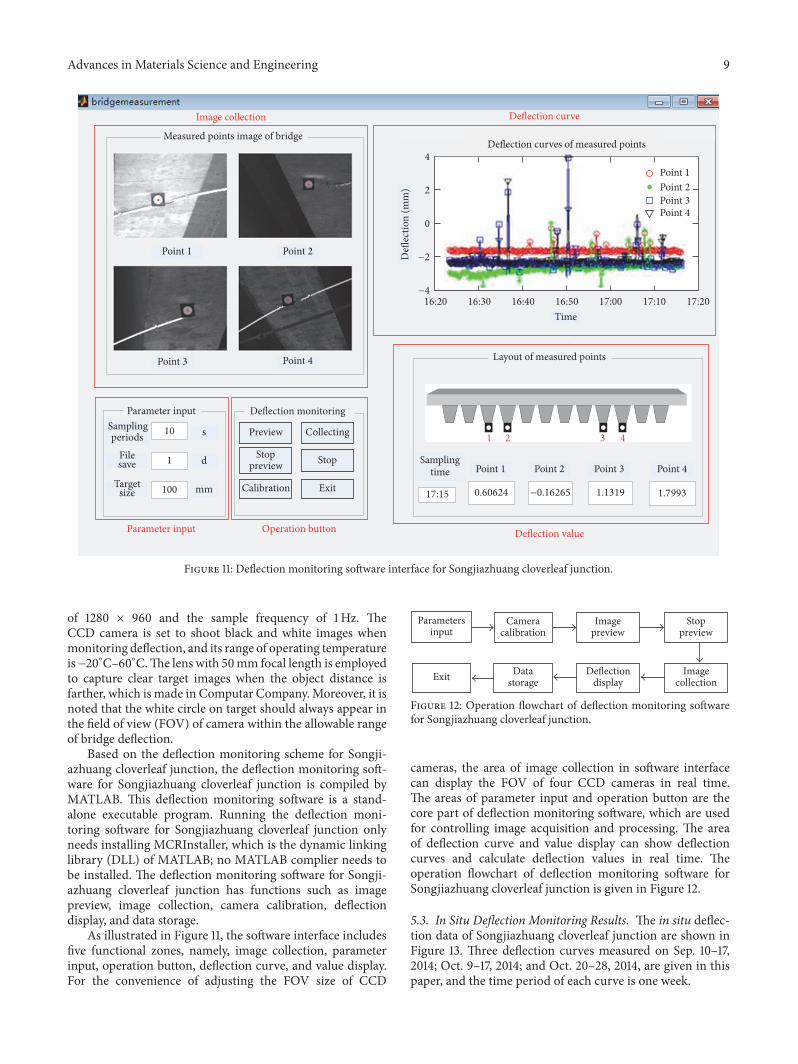
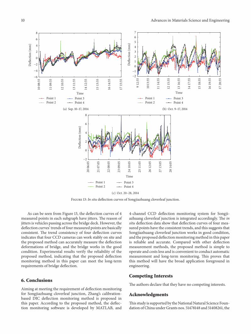