review of transmission system security and planning ... of... · review of transmission system...
TRANSCRIPT

Review of Transmission System Security and Planning Standards
Consultation Paper
September 2014

1
1 Introduction
1.1 Under Condition 20 of its Licence to Participate in the Transmission of
Electricity (the License), SONI is responsible for the planning of the
transmission system in accordance with The Transmission System Security
and Planning Standards, the Distribution System Security and Planning
Standards, the Grid Code and the Transmission Interface Arrangements as
appropriate.
1.2 Under Condition 20 SONI is also required to periodically review the
Transmission System Security and Planning Standards in consultation with the
Transmission Owner and other parties likely to be materially affected.
1.3 SONI has identified and reviewed those the elements that are specific to its
transmission license and propose to make changes as documented in this
report.
1.4 The purpose of this paper is to set out the proposed changes and seek
feedback from stakeholders.
2 Scope
2.1 The License which under which SONI operates was modified recently to reflect
the transfer of the investment planning function.
2.2 The transmission system in Northern Ireland is considered to include the
overhead lines, underground cables and substation assets operating at 275 kV
and 110 kV. The interface with the distribution system is considered to be at
the secondary terminals of the 110/33 kV transformers at bulk supply points.
2.3 The full set of Transmission and Distribution System Security and Planning
Standards is set out in Table 1. The documents were designated as NIE
license standards (with several associated amendment sheets) in 1992 and
also SONI standards in 2007. The subset of these which it is proposed to
designate as the Transmission System Security and Planning Standards
(TSSPS) and review in this paper is set out in Table 2. The documents are
available to download from the SONI website1.
1 Documents are stored at http://www.soni.ltd.uk/InformationCentre/Publications/.

2
Table 1 T&D System Security and Planning Standards
Reference Title
ER P2/5 Security of Supply
PLM-SP-1 Planning Standards of Security for the Connection of Generating Stations
to the System Issue 1
PLM-ST-4 CEGB Criteria for System Transient Stability Studies Issue 1
PLM-ST-9 Voltage Criteria for the Design of the 400kV and 275kV Supergrid System
Issue 1
ER P28 Planning Limits for Voltage Fluctuations
ER P16 EHV or HV Supplies to Induction Furnaces
ER P29 Planning Limits for Voltage Unbalance
ER G5/3 Limits for Harmonics
ER G12/2 Application of Protective Multiple Earthing to Low Voltage Networks
EPM-1 Operational Standards of Security of Supply Issue 2
Table 2 Sub set relevant to transmission
Reference Title
ER P2/5 Security of Supply
PLM-SP-1 Planning Standards of Security for the Connection of Generating Stations
to the System Issue 1
PLM-ST-4 CEGB Criteria for System Transient Stability Studies Issue 1
PLM-ST-9 Voltage Criteria for the Design of the 400kV and 275kV Supergrid System
Issue 1
ER P28 Planning Limits for Voltage Fluctuations
ER P16 EHV or HV Supplies to Induction Furnaces
ER P29 Planning Limits for Voltage Unbalance
ER G5/3 Limits for Harmonics

3
2.4 G12/2 is excluded from the Transmission Standards because it applied to low
voltage networks only. EPM-1 is also excluded from this review because it
relates to the operation of the transmission system, rather than its planning.
2.5 In addition to the License changes referred to above there have been a number
of other contributory factors to the need to review the standards:
All island transmission planning: The transmission system in Northern
Ireland is interconnected to that of the Republic of Ireland (RoI) and is a
functional part of the Single Electricity Market. There is therefore a need to
ensure that transmission planning is considered on an all island basis. It is
recognised that both systems were designed to standards which differ in
some areas, which over time will have become reflected in the specification
and design of physical assets. It is therefore accepted that some
differences shall remain. However it is planned that major items should as
far as reasonably practicable be consistent. The standard applied by
EirGrid is known as the Transmission Planning Criteria (TPC) and is
available on the EirGrid website.
The penetration of intermittent renewable generation: The original
standards were drafted to cater for base load steam turbine and nuclear
powered generators2. A large part of the generation portfolio, unlike that
envisaged when the standards where first adopted, is intermittent.
Currently there is over 550 MW of wind generation connected in Northern
Ireland with more connections planned.
Offshore transmission systems: Given the planned connections of
offshore wind and tidal generation in Northern Ireland there is a need to
establish relevant standards.
Cost benefit analysis: The general use of cost benefit analysis (CBA)
which requires the use of probabilistic techniques is now being used by
some utilities and regulators to support some investment decisions.
2 The present NI standards are based on GB documents.

4
3 GRID CODE AND OTHER LEGISLATION
Grid Code
3.1 The SONI Grid Code places an obligation on the TSO to apply the relevant
Licence Standards in the planning and development of the Transmission
System. It also requires Users to take these standards into account in the
planning and development of their own plant and systems.
Electricity Safety, Quality and Continuity Regulations (Northern Ireland)
2012
3.2 The Electricity Safety, Quality and Continuity Regulations (Northern Ireland)
2012, replacing the Electricity Supply Regulations, came into operation on 31
December 2012 and set out the obligations regarding the safe operation of
equipment and design requirements to be met. These regulations also include
requirements that are to be supported by and complement the security
standards. In brief these requirements are:
The network to be designed such as to restrict, so far as is reasonably
practicable, the number of consumers affected by any fault in the network.
(Part 1).
A distributor shall declare to a consumer the frequency and voltage to be
provided as follows (unless otherwise agreed). (Paragraph 28).
Frequency 50 Hz, with a variation not exceeding 1% above or below.
Voltage of 230 volts with variations of +10/-6 % for low voltage, +6 % for
high voltages below 110 kV, +10 % for voltage of 110 kV.

5
91
92
93
94
95
96
97
98
99
2007/08 2008/09 2009/10 2010/11 2011/12
Syste
m a
vail
ab
ilit
y
Year
NG
SONI
EirGrid
4 FAULT RATES OF TRANSMISSION SYSTEMS
4.1 In revising the planning standards for Northern Ireland it is useful to examine
the planned and unplanned availability rates for the transmission system in
Northern Ireland in comparison with similar data for GB and RoI. Consistency
between the availability of the various systems is important in any
consideration of the adoption of similar standards of planning and security.
4.2 A comparison of the total availability3 in NI, GB and RoI transmission systems
is given in Figure 1. A comparison in unplanned unavailability between NI and
GB data is given in Figure 2. The unplanned availability for the transmission
system in RoI4 by voltage is given in Figure 3. These figures indicate
reasonable consistency between the availability of the three transmission
systems.
Figure 1 – Total availability of transmission systems controlled by SONI and National Grid
3 SONI and NG have used financial years, EirGrid use calendar years.
4 Sourced from EirGrid Transmission System Performance Report 2009, 2010 and 2011

6
0
0.5
1
1.5
2
2.5
2006/07 2007/08 2008/09 2009/10 2010/11 2011/12
Un
pla
nn
ed
un
avail
ab
ilit
y (
%)
Year
GB
SONI
0
0.5
1
1.5
2
2.5
3
2009 2010 2011
Un
pla
nn
ed
un
avail
ab
ilit
y (
%)
Year
110kVplant
220kVplant
400kVplant
Figure 2 – Unplanned unavailability of transmission systems controlled by SONI and National Grid
Figure 3 – EirGrid unplanned availability by voltage

7
5 REVIEW AND COMPARISON OF STANDARDS
(i) Security of supply ER P2/5 with NIE Amendment Sheet
5.1 This standard was prepared by the Electricity Council and published in 1978.
5.2 This standard was originally based on reliability studies using fault statistics,
the value of lost load (VOLL) and the contribution from any embedded
generation, to establish the risk/cost of supply failure and compared this with
the cost of investment in the network.
5.3 The standard has a supporting document known as ‘ACE 51’ “Report on the
application of Engineering Recommendation P2/5 Security of Supply” briefly
outlining the philosophy and application. It states that the intention of security
standards is to “provide sufficient plant and other resources to provide and
maintain an economic level of reliability of supply to the consumer” and that
“simple tables formulated from experience of working conditions and system
studies should aim at setting out proposals which, if applied, would in general
give reasonable reliability of supplies at a reasonable cost”.
5.4 The intention in writing P2/5 was to present rules which would give a
reasonably deterministic approximation of the network capacity required but did
not preclude economic assessments being carried out if required.
5.5 The standard considers demand group levels from 1 MW through to 1500 MW
against six categories (Category A, B, C1, C2, D, E and F). For each of these
categories the standard provides requirements for demand to be restored
following first (N-1)5 and second (N-2 and N-M-T) circuit outages. The NIE
amendment sheet introduced a change to higher level of demand in Category
B (lowered from 12 MW to 8 MW) and a split in Category C (at 24 MW).
5.6 The categories relevant to the transmission system are C (8 MW to 60 MW), D
(60 MW to 300 MW) and E (300 MW to 1500 MW). In the original P2/5
Category F was included for demand groups in excess of 1500 MW, directing
the user to the CEGB Planning Memorandum PLM-SP-2 and Scottish Board
standard NSP 366, however this was removed in the NIE amendment sheet.
The category was considered not of practical application in Northern Ireland as
maximum demand in 1992 did not exceed 1500 MW.
Treatment of embedded generation in P2/5
5.7 Whilst P2/5 primarily specifies the levels of redundancy required for various
demand groups, it allows the designer to give consideration to the security of
supply provided by various types of embedded generation as set out in Table
2.
5 N-1 refers to normal configuration followed by a single circuit outage either planned or
forced; N-2 refers to normal configuration followed by two circuit outages; N-M-T reflects the
more credible N-2 situation of an unplanned circuit outage whilst a planned outage is on going

8
5.8 The original analysis for P2/5 Table 2 was captured in ACE 51. This was a
reliability assessment aimed at deriving what rating an additional circuit into a
demand group should have such that its contribution to meeting demand is
equivalent to the average contribution of generation in the group in terms of
‘expected energy not supplied’ (EENS). The rating of the equivalent circuit,
i.e. the ‘contribution’ of the embedded generation, was expressed as a
percentage of the installed generation capacity.
Application of P2/5 in Northern Ireland
5.9 It should be noted that transmission network in NI includes the 110 kV radial
circuits and the 110/33 kV transformers, which interface with the distribution
system. Therefore the standard must include for the aggregated demand
impact of these interface nodes. In respect of application at transmission level
it is mainly used to assess the level of security available to 275/110 kV and
110/33 kV substations. The standard can also be applied to any instance
where a group of 110/33 kV substations are connected to a section of network.
5.10 The standard can be applied also to circuits that supply groups of demand and
establishes the basis for studying N-1 and N-2 (or N-M-T) contingencies on the
transmission network. Currently N-1 is studied in all seasons, with N-2 only
studied in summer and autumn cases6 (the maintenance seasons).
5.11 For the main interconnected network connecting power stations and
interconnectors or tie lines, the standard applies in respect of the risk of losing
supply to groups of demand.
Comparison with GB and ROI standards
5.12 At the time of its formal designation as an NIE license standard in 1992 the
P2/5 standard was the applied throughout the UK. The three transmission
licensees in Great Britain, however, have since developed a composite
standard known as System Quality and Security Standard (SQSS) with
guidelines similar to the original P2/5 included. The GB DNOs, however, have
since developed a new standard, known as P2/6, which has been designated
for the connection of demand blocks in Great Britain. NIE as the distribution
network owner in Northern Ireland has recently carried out a consultation with a
recommendation that P2/6 is designated thus replacing the P2/5 standard.
5.13 The standard includes an updated method for considering the contribution to
security of supply provided by various modern types of embedded generation.
It is also noted that the SQSS does not as yet reflect the changes that have
6 The simultaneous loss of two circuits (N-2) on the backbone network is not considered to be
a credible scenario under the Standards. The loss of a circuit whilst a maintenance outage is
on-going (N-M-T) is however considered credible even though investment decisions are
normally subject to cost benefit analysis, i.e. the cost of re-dispatch during the maintenance
period is often much lower than network investment.

9
been adopted by the distribution network owners in Great Britain within P2/6.
Given the relatively small size of the Northern Ireland transmission system and
the fact that the interface is at the 110/33 kV transformers there may be a case
for greater alignment.
5.14 The current P2/5 standard, for Class E (>300 MW), refers to compliance with
N-2 (for example maintenance followed by trip) at 2/3 of the group demand. In
the 1970s when P2/5 was written the ratio of summer to winter demand was
more reflective. However this ratio now in practice often exceeds 4/5, due
mainly to the impact of air conditioning demand which increases in summer. It
is noted that the SQSS standard recognises this change in demand
characteristics and now refers to the maintenance period demand rather than
any specific percentage. Any new Northern Ireland standard should also
consider this change.
5.15 In RoI, the Transmission Planning Criteria (TPC) doesn’t have an equivalent
table, however there is a recommendation that multiple 110/38 kV stations
supplying demand in excess of 80 MVA, or up to four 110/38 kV substations,
should not be isolated for an N-2 event. This requirement would be implicit
within Category D (60 MW to 300 MW) of P2/5 which requires a re-supply to
1/3 of group demand within 3 hours for an N-2 event. If two adjacent 110/33
kV substations were disconnected for an N-2 then it is unlikely that the 1/3 re-
supply requirement could be met. The practice in Northern Ireland has been to
connect 110/33 kV substations as individual transformer feeder arrangements
unless introduced as a node on the main interconnected transmission system.
Latest Practice by ENTSO-E
5.16 ENTSO-E has published approaches to transmission planning in the 2012 Ten
Year Network Development Plan (TYNDP). Appendix 3 of the 2012 TYNDP
includes a separately published document “Guidelines for Grid Development”.
The document does not specify redundancy requirements for varying levels of
group demand such as are included in P2/5. The document does, however,
refer that the maximum loss of load should not exceed the active power
frequency response.

10
Cost Benefit Considerations
5.17 The Council of European Energy Regulators (CEER) gives European
guidelines7 on estimating the costs of electricity interruptions and voltage
disturbances, recommending that “National Regulatory Authorities should
perform nationwide cost-estimation studies regarding electricity interruptions
and voltage disturbances”.
5.18 It is understood that most countries design demand connections to an N-1
criteria with a cost benefit analysis used to justify investment to an N-2 level.
Proposal
5.19 The review by NIE of the distribution planning standards has resulted in a
proposal by NIE for the designation of ER P2/6 replacing P2/5 in the set of
Distribution System Security and Planning Standards. It is therefore proposed,
for a consistent approach across the system, that the new transmission
standard should take account of the techniques within P2/6. Assessment of
capacity to supply demand should use demand values that have been modified
to allow for embedded generation with the appropriate factors already applied.
A reference to the Distribution System Security and Planning Standards would
be used to capture this approach. For larger, perhaps 33 kV connected
generation, it is considered that this should be modelled separately within the
transmission studies but that the same techniques in terms of contribution to
security of the supply to the demand group should be assumed.
(ii) Connection of generation PLM-SP-1
5.20 The CEGB Planning Memorandum PLM-SP-1 was published in September
1975 to set out the requirements for connection of generation. The document
sets out the requirements for the capacity and number of circuits required to
connect generation in terms of multiples of the largest single generating unit,
which at the time was 660 MW in Great Britain.
5.21 In summary the document recommended that generating units up to 660 MW
could be connected with a single circuit, with groups of generating units
between 660 MW and 1320 MW being connected by at least two circuits.
Above that at least three circuits were required. The document also prescribed
limits to the length of 400 kV and 275 kV circuits to connect generating power
stations.
5.22 When designated as a license standard in Northern Ireland an amendment
sheet was included which reduces the level for at least three circuits from 1320
MW to 550 MW (due to the predominant use of double circuits it was actually
described as four circuits). At the time the transmission system in Northern
7 Guidelines of Good Practice on Estimation of Costs due to Electricity Interruptions and Voltage Disturbances,
CEER, December 2010. Other reports have also established such guidelines, such as CIGRE (2001) and EPRI (

11
Ireland was an isolated system (North South interconnector was restored to
service in 1995) and the largest generating unit was approximately 260 MW.
Maximum distance of a generation connection circuit
5.23 The PLM-SP-1 set limits on the maximum distance of 400 kV and 275 kV
generation connection circuits for high and low load factor power stations to 5
km and 20 km respectively. It is understood that these limits were primarily
applicable to generator owned circuits in Great Britain. In Northern Ireland this
situation does not arises apart from relatively short connecting cables within the
power station complex.
5.24 PLM-S-1 is silent regarding the length of 110 kV connections. A limit for 110
kV connections is likely to become a barrier to the economic and timely
connection of key renewable generators in the future, possibly risking
renewable generation targets. It is suggested, since NI is relatively small in
geographic terms that the number of instances that generators would connect
using 110 kV circuits in excess of the distances specified above will be
relatively few. Also with 110 kV applications other factors such as fault level
and voltage regulation will lead to a natural limit on the length of 110 kV
connection circuits, depending on the capacity required. It is therefore not
proposed to extend these limits to the connection of 110 kV connected
generators or clusters. The issue should be kept under review.
5.25 For 275 kV and 400 kV connections the scale of generation that could be
connected would be up to the largest single infeed. Again however the
application of the limit could be a barrier to the connection of offshore
generation in particular. It is proposed however to retain the 5 km limit for large
base load onshore generation.
Intact system and under credible contingencies
5.26 PLM-SP-1 specifies that a new generation connection shall not cause voltage
violations (Clause 2.1.4) or system instability (Clause 2.1.5). Clause 2.1.4 also
states that frequency and voltage will be maintained within equipment ratings
(assumed to indicate thermal current ratings). The SQSS has also included
these elements (Clauses 2.9.1, 2.9.2 and 2.9.3).
5.27 PLM-SP-1 also refers that the above will apply during credible contingencies.
The SQSS specifies that for these conditions there are no equipment overloads
(2.10.8), voltage violations (2.10.9) and that there is no loss of demand apart
from that specified in P2/5 (2.10.7).
5.28 It is considered imperative to retain the above provisions in any updated set of
standards.

12
Largest Single Infeed
5.29 The Largest Single Infeed8 (LSI) can be defined as a block of generation
consisting of a single large unit, a group of units, or an interconnector
importing, connected to the all-island power system via a single transmission
circuit, the loss of which would result in the loss of the entire block of
generation. The LSI is used in RoI in the TPC to define the requirements for
the connection of generation, however the actual level is not stated.
5.30 PLM-SP-1 specified that the largest single generation connection in GB was to
be 660 MW (Clause 3.1). The NIE amendment sheet however does not align
with this value, instead setting the requirement for at least three circuits to 550
MW reflective of the smaller system. As a consequence the largest set in NI
was never envisaged as 660 MW. It can be inferred from the NIE Amendment
Sheet, since the limit requiring N-2 security (reserved for a group of generation
of twice the largest single infeed) was set for 550 MW that the LSI in NI at the
time of privatisation was considered to be 275 MW. The actual LSI in 1992
was Kilroot G1 and G2 which each had a capacity of 260 MW (on oil).
5.31 When the North – South interconnector was restored in 1995 generating
reserve was shared. Since then, larger power infeeds have been
commissioned in NI, including the Moyle Interconnector9 (connection of 450
MW) in 2002 and Coolkeeragh CCGT (414 MW) in 2005. On the all island
basis the East West Interconnector (EWIC) was connected in 2012 raising the
LSI to on the island to 500 MW. To be consistent on an all island basis it is
proposed that the LSI for the NI standard should be clearly defined as 500 MW.
Generators or groups up to the capacity of the largest single infeed
5.32 In terms of the number of circuits required Clause 2.1.2 of PLM-SP-1 states
that no single fault shall cause the instantaneous loss of generation greater
than the single largest infeed. From a minimum standard it therefore follows
that a single connection circuit is acceptable for the connection of generators
up to the LSI.
5.33 The 2004 version of the SQSS specified the same, however, this was amended
in the most recent version in 2012, recommending that up to 1320 MW can be
connected via a single generation connection circuit. This change came from a
review carried out by the transmission owners (TO) in GB.
5.34 In RoI, the TPC states that any group of generators with a combined capacity
in excess of the LSI shall have two generation connection circuits (section 4.2
8 The Largest Single Infeed is an important concept in that it dictates the level of generation
reserve and automatic under frequency load shedding that the TSO requires to provide for.
9 Whilst the Moyle Interconnector has two poles it is connected to a single 275kV circuit in
Scotland, thus could be lost for a single contingency.

13
iv). Therefore, it follows that for a generator smaller than the LSI, a connection
with a single circuit is acceptable. Thus this is consistent with the SQSS.
5.35 It is proposed that the new standard shall recommend a single circuit is
acceptable for generators or groups thereof with total capacity up to the LSI,
set at 500 MW.
Generator groups in excess of once but less than twice the largest single
infeed
5.36 PLM-SP-1 (clause 3.2.1) specifies that two circuits are required for generation
connections up to twice the single largest infeed (Clause 3.2.1).
5.37 In RoI the TPC also states that two circuits are required for a group of
generators with a capacity in excess of the LSI. On that basis it would appear
permissible for a capacity of twice the largest single infeed to be lost for the
loss of two circuits.
5.38 It is proposed that for a group of generating units above the LSI that two
circuits will be required. However considering the relatively small size of the
Northern Ireland transmission system, the widespread use of double circuit
tower lines and its limited interconnections this is capped at 1.3 times the LSI is
proposed, i.e. 650 MW. This can be reviewed as appropriate when further
interconnection is established.
5.39 The standard should also allow for the use of operational intertripping to reduce
the generation output provided that does not introduce excessive complexity
(assessed by risk assessment), frequency or instability problems and can be
economically justified on a case by case basis.
5.40 The PLM-SP-1 standard (with NIE amendment sheet) suggested that it would
be normal for power stations over 550 MW (NIE Amendment sheet Revision 2)
would be connected via four circuits (i.e. secure after an N-2). The definition of
four circuits of course was reflective of the practice in Northern Ireland to use
double circuit tower lines. The main objective however was that the connection
would be secure for an N-2 event. The equivalent in the SQSS is the
infrequent infeed loss risk (2.6.1 and 2.6.3) which is currently 1320 MW. The
SQSS states that following the loss of a double circuit tower line the maximum
that can be lost is the infrequent infeed loss risk (Clause 2.6.4). Above this
level (1320 MW) it is assumed that if a DCT is used in the connection it must
be supplemented by at least one additional circuit.
Generators above 1.3 times the largest single infeed
5.41 The TPC specifies that for generation in excess of twice the largest generation,
it shall be possible to transmit the full output less one generating set in a trip
maintenance (or N-M-T) condition (see Clause 4.2.iv). Thus this standard
envisages that the output of the station could be constrained during the initial
maintenance outage.

14
5.42 As stated in 5.39 it is proposed to limit the application of two circuits up to 1.3
times the LSI. Above this it is proposed that at least three circuits are required.
If provided by double circuit tower lines then four circuits would be required.
Busbar arrangements
5.43 PLM-SP-1 sets standards for the busbar arrangements to connect various
levels of generation. For certain outages on the transmission system it is
accepted that there is a risk of losing connected generation. A comparison
between PLM-SP-1, relevant sections of the SQSS and TPC relating in this
regard are shown in Table 1.

15
Table 3 – Comparison of busbar requirements
Contingency Loss of power
PLM SP 1 SQSS TPC
Fault outage of any
single generation
connection circuit
Largest authorised
generator (2.1.2)
Infrequent
infeed risk,
1320MW
(2.6.3)
Largest set
(4.2 ii)
Planned outage of any
busbar section
Not directly specified,
however historically in
practice no loss of
infeed for transmission
connected.
No loss of
power
infeed
(2.6.2)
Not
specified
A fault outage of any
single busbar section
No greater than the
largest set (2.1.3).
No greater
than the
largest set
(4.2 ii)
A fault outage of bus
section or bus coupler
circuit breaker
No greater than twice
the largest set (2.1.3).
No greater
than twice
the largest
set (4.2 ii)
A fault outage of
transmission circuit or
busbar section, during
the planned outage of a
transmission circuit or
busbar section
The current NI standard
specifies that there is
no loss of power
greater than twice the
single largest infeed
(NIE Amendment Sheet
Revision 2).
No loss of
power
greater than
twice the
single
largest
infeed.
Not
specified
but by
implication
of 4.2 ii
considered
same.
A fault outage of bus
section or bus coupler
circuit breaker, during
the planned outage of
any busbar section
Twice the single largest
infeed (NIE
Amendment Sheet
Revision 2).
Infrequent
infeed loss
risk
(1320MW)
Not
specified

16
Definition of generation connection circuit
5.44 Consideration should also be given, if one combined standard is developed,
that two classes of circuit are defined, i.e. a) a generation connection circuit,
and b) a main interconnected transmission circuit, as defined in the GB SQSS.
Some circuits can of course be classed as providing both functions as there is
often an overlap. This would help to clarify how each circuit is to be considered
in the standards, i.e. must comply with N-1 or in the case of a generation circuit
would allow a limited loss of generation infeed.
5.45 The existing standards clearly define the need for double busbar arrangement
for the connection of conventional generation.
Levels of embedded generation connected to 110/33kV substations
5.46 PLM-SP-1 being a transmission standard doesn’t offer any specific guidelines
on the levels of embedded generation that can be connected at cluster type
and mixed demand type 110/33kV substations.
5.47 In such scenarios the level of generation will always be lower than the LSI and
therefore N-1 security is not required. Therefore at cluster substations a single
110/33kV transformer, rated accordingly, is acceptable. If two transformers are
required then it would be the combined capacity that would be assessed
against the peak generation with no redundancy. For the loss of one
transformer the remaining generation would have to be constrained.
5.48 However, in substations that also have significant demand connected the P2/5
security of supply standard, or replacement provisions, should be respected.
Therefore generation cannot be connected such that it would overload the
remaining in service transformer under n-1 and as a result cause the loss of
demand potentially above that specified in P2/5. There are other factors such
as operability issues, transformer life, losses, voltage step changes, reactive
power requirements, flicker and harmonic headroom with the associated risks
assessed on a case by case basis.
5.49 It is proposed that the new standard should cater for instances where the flows
from generation embedded within the distribution system interface with the
transmission system at a bulk supply point. It does not seem prudent to specify
an arbitrary limit on this but state that operational intertripping can be used to
reduce the level of embedded generation to protect a second transformer from
overload risking the loss of demand customers.
(iii) PLM-ST-9; Voltage Criteria
5.50 CEGB Planning Memorandum PLM-ST-9 published in December 1985. The
document sets out the voltage requirements in terms of upper, lower and step
limits. In GB the voltage regulation requirements are as set out in Section 6 of
the SQSS. In RoI similar requirements are set out throughout the TPC.

17
5.51 A Comparison of NI, ROI and GB voltage lower and upper limits is given in
Table 4 and 5. The NI and GB SQSS (England and Wales) standards are
identical. The RoI standard permits a higher voltage rise on the 220kV and
110kV networks, both during system normal and fault conditions. The limits
above have been designed over time into the transmission systems in Northern
Ireland and RoI.
Table 4 – Comparison of lower voltage limits (pu)
Case Nominal
Voltage
Lower limit (pu)
NI RoI (TPC) GB (SQSS)
England
and Wales
SPT and
SHETL
areas
System
Normal
400kV 0.925
(Section
2.2.6)
275/220kV 0.95 0.954 0.95 0.95
110/132kV 0.95 0.954 Note 2 Note 1
Contingency 400kV 0.875
275/220kV10 0.9 0.91 0.9 0.9
110/132kV 0.9 0.9 Note 3 Note 3
Note 1 – There is no minimum planning voltage provided that Note 3 can be
observed for a lower voltage derived from the 132 kV transmission system.
Note 2 – There is no minimum planning voltage for a lower voltage supply
provided that it is possible (e.g. by tap changing) to achieve up to 105% of
nominal voltage at the busbar on the LV side of a transformer stepping down
from the onshore transmission network at a GSP
Note 3 – it shall be possible to operate the busbar of a GSP up to 100% of
nominal voltage unless the fault includes a supergrid transformer.
The standards are identical across NI, RoI and GB, with the exception of the
132kV voltage in the GB standard both for system normal and during a fault.
10 275kV used in GB and NI, 220kV used in RoI

18
Table 5 - Comparison of Upper voltage limits (pu)
Voltage NI RoI (TPC) GB (SQSS)
System
Normal
400kV
275/220kV 1.05 1.09 1.05
110/132kV 1.05 1.09 1.05
Contingency 400kV
275/220kV 1.05 1.09 1.05
110/132kV 1.05 1.09 1.05
5.52 The voltage step change limits are given in Table 6. The voltage step change
for switching events on the network is identical across NI, RoI and England and
Wales. The voltage standard for N-1 events is the same in NI and GB (±6%),
however, ROI permits a voltage step change of ±10% for N-1 events. For N-
DCT events, the NI standard permits a voltage step change of ±10%. In
Scotland the lower voltage limit for an N-DCT can be -12% (with an upper
voltage limit of +6%). It is proposed to retain the existing step change limits.

19
Table 6 Voltage step change limits in NI, GB and ROI
NI TPC GB (SQSS)
England
and Wales
SPT SHETL
System
Normal
Switching ±3% ±3% ±3% Doesn’t
specify
Doesn’t
specify
N-1 ±6% ±10% ±6% Note
4
±6%
Note 5
±6%
Note 6
N-DC ±10
%
Note
7
±6% +6%, -
12%
+6%, -12%
Note 4: Can be -12% if fault includes section of busbar, mesh corner or
supergrid transformer.
Note 5: Can be -12% for loss of a double circuit.
Note 6: Can be -12% for loss of a double circuit, section of busbar, mesh
corner or supergrid transformer
Note 7: The ROI system is mainly constructed with single circuits thus a figure
for the loss of a DCT is not specified in the TPC.
(iv) PLM-ST-4; Transient Stability
5.53 The CEGB Planning Memorandum PLM-ST-4 published in September 1975
was adopted with an NIE amendment sheet in 1992. The standard outlines the
transient stability criteria. The NIE amendment sheet 2 states that the system
shall remain stable following a three phase fault to any circuit, at all levels of
system demand, and with a reasonable number of other circuits out for
maintenance.
Comparison with SQSS
5.54 The SQSS splits instability into the areas of generation connection, the
connection of demand blocks and the main interconnected network. However
the SQSS requires that there must not be instability for the full range of
secured events on the transmission system. The definition of system instability
within the SQSS is regarding loss of synchronism of generators and poor
damping of oscillations. It expands to require that the worst single failure of
protection musts also be considered and is consistent with the PLM-ST-4.
Transmission Planning Criteria
5.55 The TPC, in Section 2.2.2 makes the following requirements with regards to
transient stability in reference to generator rotor angles and pole slipping: “The
strength of the system shall be such as to maintain stability following a three-
20
phase zero impedance line-end fault. It shall be assumed that the fault is
cleared by primary protection and that line re-closing is in operation where
appropriate.”
Proposal
5.56 The SQSS includes for the loss of a single item of protection as was also
required in the PLM-ST-4. The Northern Ireland transmission system at 275kV
includes double main protection as required by PLM-ST-4 and also with the
SQSS requirements. The 110kV system has high speed primary protection but
lower speed backup. It is proposed that the standard should allow for the loss
of primary protection at 275kV and above.

21
6 MAIN INTERCONNECTED TRANSMISSION SYSTEM STANDARD
Need for backbone standard in NI
6.1 Whilst the NI standards include for generation entry to (PLM-SP-1) and
demand exit from (P2/5) the transmission system the set designated in 1992
did not include a standard for the main interconnected transmission system.
The NI network being relatively small with a large degree of overlap between
generation connection circuits and demand exit such a standard may not have
been considered necessary.
6.2 In practice the main interconnected transmission system has been assessed
according to an N-1 standard with N-DCT and N-2 risks either being managed
with intertripping schemes or justified through cost benefit analysis. It is
important however to confirm the practice into a standard.
6.3 It is also important to confirm the applicable generation dispatches that should
be considered, for example merit order only or stressed case and also include
information on the assumptions regarding the operation of the all island
transmission network including interconnectors.
Generation Dispatch Assumptions
6.4 A key consideration in transmission system assessment is the assumed
location, size and availability of present and future generating units. Planners
should model future generation, for example based those that have connection
offers or have received planning permission. Also generation that is planned to
retire perhaps must also be considered. The risk that generating units can be
rendered not available for prolonged periods due to mechanical or electrical
failure is also an important consideration.
6.5 The three common types of generation dispatch used in transmission planning:
economic dispatch (also referred to as merit order)
stressed dispatch and
flat dispatch.
Each will result in a different pattern of generation and subsequent
transmission loadings and voltage performance. These different transmission
performance outputs can affect what transmission investments are required.

22
6.6 The economic dispatch assumes that all generation is available and is
dispatched according to its merit order also making an allowance for operating
margin. A range of wind generation assumptions should also be included.
This type of dispatch leads to the development of a transmission system which
favours the least cost generation however it can also restrict the versatility of
the transmission network to generation outages.
6.7 It is also necessary to include ‘stressed’ system conditions. For example, the
long term outage of generator perhaps at a load centre or an interconnector
infeed. Such long term outages, perhaps due to equipment failures, may take
some years to repair owing to financing uncertainty and long procurement lead
times for specialist plant, during which time other network contingencies will
also occur. Transmission investment planners should consider if during
stressed conditions such as long term generation or interconnector outage that
the transmission system will perform adequately for a range of the more
common contingencies, such as N-1 and possibly N-DCT.
6.8 The flat dispatch results in the same level of scaling across each generator
regardless of merit order. The flat dispatch is not based however on economic
dispatch or a predictable stressed case.
6.9 It is proposed that the standards will include an economic dispatch and a
number of stress tests.
National Grid Generation Dispatch Assumptions
6.10 It is useful to review the approach taken by National Grid in terms of generation
dispatch assumptions. The SQSS has a section 4 entitled “Design of the Main
Interconnected Transmission System”. This section refers to two main studies.
One at the winter peak Average Cold Spell (ACS) and others over the course
of a year. The ACS study refers to two alternative generation assumptions:
Security planned transfer condition
Economy planned transfer condition
6.11 The outputs of generators can also be set up to allow flows from one area to
another, known as the Interconnection Allowance. In terms of generation
assumptions the standard recommends that typical planned outage patterns
should be considered11. The standard recommends that there should be no
overloads, or voltages outside standard, for single circuit loss and for the loss
of both circuits of a double circuit tower line. Whilst the standard covers
SHETL, SP and NGET systems the latter network area must also cover a
maintenance followed by trip condition (N-M-T).
11 In terms of reactive power, the standard recommends that either a reactive capability chart
is used, or that the maximum output set to 90% of that specified by the Grid Code.

23
6.12 The requirement to cover N-M-T in NI, however, would allow re-dispatch after
the maintenance condition. Post fault re-dispatch in Northern Ireland is more
difficult because there is no policy on emergency ratings.
6.13 The use of the Security planned transfer condition is to ensure that the network
in GB has sufficient capacity to allow indigenous conventional plant to supply
the demand. Interconnector flows and intermittent generation outputs are
therefore set to zero.
Transmission Planning Criteria
6.14 The TPC states that the base case must be set up with a credible generation
dispatch, although this may be out of merit, to allow for abnormal generation
conditions. The pre-fault case should be set up to include any operational
measures that would be available to aid in mitigation in the event of a
contingency.
6.15 The TPC also sets out “more probable” and “less probable” contingencies.
More probable contingencies include N-1 and N-1-1 (or N-M-T), and must not
lead to breach of normal limits (after enacting allowable remedial actions12) or
emergency limits before remedial actions (typically 10% above normal). The
less probably contingencies include busbar faults and N-DC and must not
result in voltage collapse or cascade tripping.
6.16 The normal N-1 contingency is covered but also the requirements for N-M-T.
During the first maintenance re-dispatch is allowable. Also following the fault it
is acceptable to change power flow controller setting and also re-dispatch
online plant and fast response offline units.
6.17 In NI circuit ratings are based on ER P27 multi-circuit ratings. The use of
emergency ratings cannot be used at this time because these have not been
defined for NI.
6.18 The NI 275kV transmission system is almost entirely constructed with double
circuit tower lines, and the loss of both circuits is more probable than an N-M-T
condition, mainly due to weather phenomena such as ice accretion. The
220kV system in RoI is mostly constructed with single circuit tower lines.
ENTSO-E
6.19 The ENTSO-E TYNDP 2012 includes “Guidelines for Grid Development” in
Appendix 3. In particular Section 12.2.3 sets out the standard
recommendations for analysis and investment. The section states that
currently deterministic criteria are used for planning.
6.20 The section differentiates between normal, rare and out of range contingencies.
12 Such as tap changing, phase angle regulators, generation redispatch, switched shunts and
network switching

24
6.21 A normal contingency is the (not unusual) loss of one of the following elements:
generator;
transmission circuit (overhead, underground or mixed);
a single transmission transformer or two transformers connected to the same bay;
shunt device (i.e. capacitors, reactors);
single DC circuit;
network equipment for load flow control (phase shifter, FACTS …) or
a line with two or more circuits on the same towers if a TSO considers this appropriate and includes this contingency in its normal system planning.
6.22 A rare contingency is the (unusual) loss of one of the following elements:
a line with two or more circuits on the same towers if a TSO considers this appropriate and does not include this contingency in its normal system planning,
a single busbar,
a common mode failure with the loss of more than one generating unit or plant or
a common mode failure with the loss of more than one DC link.
6.23 An out-of-range contingency includes the (very unusual) loss of one of the
following:
Two lines independently and simultaneously;
a total substation with more than one busbar or
loss of more than one generation unit independently.

25
6.24 The document suggests that normal (N-1) and rare contingencies (N-DCT)
could result in investment backed if necessary by cost benefit analysis. The
out of range contingencies would not normally result in investment provided the
risk can be managed by other means, for example, re-dispatch during the
maintenance period. In considering the recommendations from ENTSO-E as
set out in this document the practices currently carried out would be consistent
with current EirGrid and NI practice.
Assumptions regarding wind generation
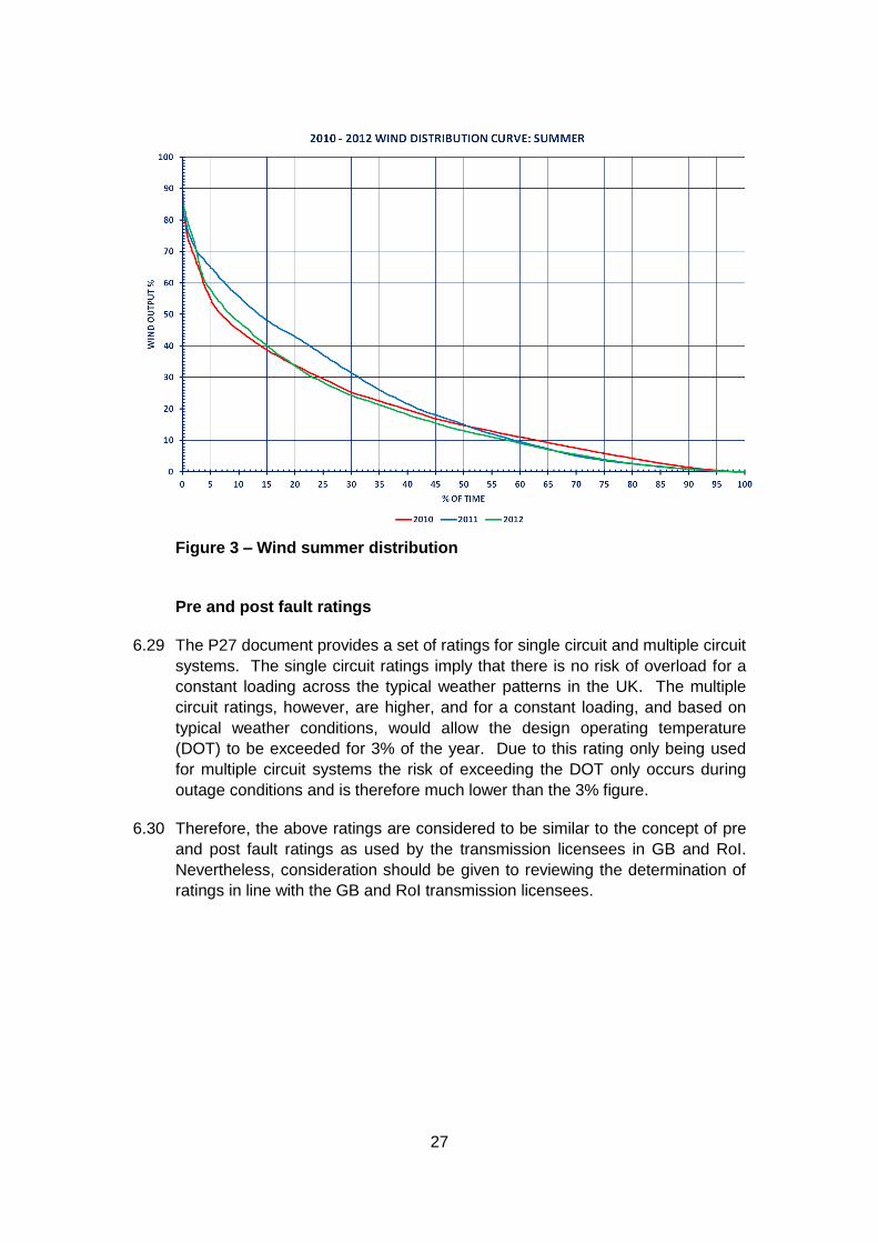
6.25 Analysis carried out by SONI has shown that wind generation has a low load
factor and also across a wider geographical area has an increased level of
diversity. Figure 1, 2 and 3 show the wind output distribution for the three
seasons within 2010, 2011 and 2012. There are variations between the three
years studied and between the three seasons. The minimum demand and
lowest circuit rating would occur in summer. It is seen that for the summer
season, the wind only exceeds 70% of installed capacity for no more than 3%
of the time, with wind in excess of 85% being almost non-existent. This
suggests that setting the level of wind generation to the installed capacity
across the system is not credible.
6.26 It is also noted that similar observations would appear to have been made in
GB, as included in the SQSS for Economy planned transfer condition.
Appendix E of the SQSS sets out the dispatch conditions assumed for an
economic dispatch and it is noted that wind, wave and tidal generation should
be scaled to 0.7 times the installed capacity.
6.27 It is considered that a certain wind generation dispatch should only be
highlighted for further examination if they are in existence for greater than 3%
of the time. Based on historical data it is recommended that for screening
studies wind generation is dispatched at no more than 70% in summer min,
80% in summer max and 90% in winter peak. Before investment is sanctioned
a cost benefit analysis is also likely to be carried out using data across the
year.
6.28 It should be noted that this analysis relates to the operation of all wind
generation in Northern Ireland. The actual shallow connection circuits to an
individual wind farm or cluster substation will have much less diversity due to
the smaller geographic area. For a single wind farm the developer could
oversize the wind turbines and cap there output thus ensuring that it makes full
use of its maximum export capacity. It is therefore proposed that the shallow
connection circuits should always be rated to at least 100% of the agreed
maximum export capacity.

26
Figure 1 – Wind winter distribution
Figure 2 – Wind autumn distribution
27
Figure 3 – Wind summer distribution
Pre and post fault ratings
6.29 The P27 document provides a set of ratings for single circuit and multiple circuit
systems. The single circuit ratings imply that there is no risk of overload for a
constant loading across the typical weather patterns in the UK. The multiple
circuit ratings, however, are higher, and for a constant loading, and based on
typical weather conditions, would allow the design operating temperature
(DOT) to be exceeded for 3% of the year. Due to this rating only being used
for multiple circuit systems the risk of exceeding the DOT only occurs during
outage conditions and is therefore much lower than the 3% figure.
6.30 Therefore, the above ratings are considered to be similar to the concept of pre
and post fault ratings as used by the transmission licensees in GB and RoI.
Nevertheless, consideration should be given to reviewing the determination of
ratings in line with the GB and RoI transmission licensees.

28
Use of special protection schemes to control intermittent generation
6.31 There are several SPS schemes in place in Northern Ireland. The experience
of the schemes however is that:
The schemes can be complex and require significant contribution from a
limited technical expertise to design, install and maintain;
Some of the equipment, for example temperature probes, have had reliability
issues;
In order to be sufficiently trusted the schemes require redundancy in terms of
hardware and communication links adding additional cost;
The cost of constraining pre fault can often be more economic than investing
in complex and expensive hard wired special protection schemes;
Network upgrade can renders certain schemes redundant adding cost to
recover or amend the schemes;
The operation of overlapping schemes on the main interconnected
transmission system can be difficult to predict and model;
The tripping of a large numbers of wind generation sites has to be limited by
the level of spinning reserve otherwise risking under frequency load shedding.
6.32 In general schemes that involve overload risks on the main interconnected
transmission system with tripping multiple wind farms over long distances using
rented pilots should be avoided or subject to detailed risk assessment. SPS
with a simple design purely to cover a local constraint, for example transformer
capacity at a 110/33kV substation, will still be considered however the
implications for power quality should be assessed.
Proposals
6.33 In terms of dispatch assumptions it is proposed that there should be two main
types of study, i.e. one with economic all island dispatch and a further set of
stressed case scenarios. The stressed case scenarios may include long term
interconnector outages, long term generator outages and operation of in merit
generators at full output.

29
7 REVIEW OF STANDARD FOR LIMITS FOR HARMONICS (ER G5/3)
Description of ER G5/3
7.1 ER G5/3, published in 1976, provides limits of harmonic currents to be fed
into the electricity network thus limiting the overall voltage distortion at
planning levels which are set to achieve compatibility with user’s
equipment.
7.2 Since the publication of ER G5/3 the structure of the electricity supply
industry has changed significantly. Moreover European Legislation, in
particular the ‘EMC Directive’, has been implemented, adding mandatory
product specific requirements in terms of compatibility and emissions.
7.3 There has been considerable activity in the formulation of a series of
International Electromagnetic Compatibility Standards and Technical
Reports concerned with low frequency phenomena. The driving force
within Europe has been the ‘EMC Directive’ of the European Union. The
Directive has been enacted within the UK by the EMC regulations, which
came into force in January 1996. This Directive seeks to ensure the
removal of technical barriers to trade by:
Enabling equipment to operate satisfactorily in its specified environment
and
Protecting the public electricity distribution system from electromagnetic
disturbances emitted by equipment by limiting emissions so that other
connected equipment does not malfunction.
Adoption of ER G5/4
7.4 A review of ER G5/3 in light of the EMC standards, in particular the IEC 61000
series has highlighted a considerable number of aspects that needed revision.
This has resulted in the publication of an updated standard ER G5/4 which has
compatibility and planning levels based on IEC and CENELEC standards are
now given in ER G5/4. ER G5/4 now:
covers all voltage levels from 400V to 400kV (ER G5/3 covered up to
132kV);
covers harmonics up to and including the 50th harmonic;
introduces guidance including sub-harmonics, inter-harmonics, and
voltage notching.
7.5 G5/4 was further updated to G5/4-1 allowing for the application of a ‘Partial
Weighted’ methodology for higher frequency harmonics and ‘Conditional
Connections’.
7.6 EirGrid has adopted the requirements set out in IEC/TR 61000-3-6
recommended methodology for transmission in Appendix D. The main
difference between IEC/TR 6100-3-6 and ER G5/4 is that the latter offers

30
headroom on a “first come first served” or “straw that breaks the camel’s back”
basis, whereas then the IEC allocates headroom based on proportion of
demand or generation.
Proposal
7.7 It is considered necessary that the standard used to assess transmission
connections should be harmonised to that proposed to be applied to the
distribution system. It is therefore proposed to designate G5/4-1 to replace
G5/3 as a transmission standard.

31
8 OFFSHORE WIND GENERATION CONNECTION STANDARD
Background
8.1 The arrangement in GB involves the installation of an Offshore Transmission
System generally installed by the developer under contestability and then
transferred to, and owned by, a licensed Offshore Transmission Owner
(OFTO).
8.2 In NI there is as yet no provision for an OFTO approach to ownership of
offshore assets.
8.3 For the purposes of defining a standard, however, it is considered that an
offshore transmission system should be defined similar to the reference in the
System Security and Quality of Supply. The transmission standards as defined
shall apply to the assets regardless if the final owner/operator.
Cost benefit analysis conducted in GB
8.4 The current SQSS was developed using a set of studies detailed in a report
“Cost Benefit Methodology for Optimal Design of Offshore Transmission
Systems” published by the Centre for Sustainable Electricity and Distributed
Generation. This document was used in the development of the section of the
SQSS. The report main findings were:
The number of offshore cables should be minimised with no planned
redundancy;
Total capacity of the cables may be lower than the maximum export
capacity (MEC) of the wind farm, due to diversity;
Maximum rating of a single transformer connecting a wind farm should be
90MVA (due to the cost of the expected energy constrained and the MTTR
of a single transformer);
Cost benefit analysis showed that a 132kV double circuit overhead line
could be used depending on distance. At greater distance the additional
cost however became more difficult to justify.
8.5 Upon review of the above the recommendations, it is accepted that there
should be no redundancy, except for that available if two circuits are required
for capacity. The under-sizing of the connecting circuits lower than the MEC on
the forecast that there will be diversity is not supported. Cables would be
installed according to standard sizes and given the installation cost under
sizing on the rating of the cable is not supported.
Reactive support connection
8.6 For offshore connected wind generation it is accepted in Great Britain that the
reactive support requirement is provided at the onshore grid entry point (GEP)

32
with the power factor at the offshore platform GEP kept at unity. This was on
the basis that offshore wind farm connections would be radial only. It is noted
however that the ENTSO-E Network Code Requirements for Generators (RfG)
has set the required level of reactive support at the Connection Point (OffGEP)
to 0.66 MVAr/MW (equating to a power factor of 0.95 leading to 0.95 lagging).
This requirement makes provision for offshore connections in the future to
become meshed rather than pure radial connections. It is expected that this
will in the future be adopted into the Grid Code.
8.7 It is accepted that in the case of a radial connected wind farm the cable will
provide reactive power. It is proposed therefore that the standard will allow a
proportion of reactive power to be provided by the wind turbines connected to
the offshore platform and the cable charging. However if the Grid Code is
changed then the standard shall will require to comply.
Proposed limit of a single offshore power station
8.8 The studies in GB were based upon the connection of single offshore power
stations up to 1500MVA in size. At the time the normal infeed loss risk13 was
based upon a capacity of 1000MW, although this is due to rise to 1320MW in
2014. In NI, and the all-island system, the largest single infeeds are 450MW
(Moyle) and 500MW (EWIC) respectively. Therefore for the purposes of a new
NI standard, the recommended largest single infeed from a single wind farm
should be established at 500MW.
13 Loss of generation that would cause a 0.5Hz deviation.

33
9 COST BENEFIT ANALYSIS
Current Practice in Northern Ireland
9.1 It is useful to refer to HM Treasury guidance as set out in “THE GREEN BOOK
- Appraisal and Evaluation in Central Government” and also the Northern
Ireland Department of Finance and Personnel website guidelines entitled
“Northern Ireland Guide to Expenditure Appraisal and Evaluation (NIGEAE)”.
These documents acknowledge that performing a cost benefit analysis is a
time consuming effort. The extent of effort should therefore be proportional to
the level of investment being proposed.
9.2 Cost benefit analysis was carried out in support of the upgrades for the Medium
Term Plan. This included a comparison between the cost of constraining wind
generation and the cost of the reinforcement projects.
Current Practice in RoI
9.3 The Transmission Planning Criteria also states in section 1.3 that any
transmission plan proposed for adoption under the criteria must ultimately be
justifiable taking account of economic, financial, strategic and environmental
considerations.
ENTSO-E Guidelines
9.4 ENTSO-E has produced the “Guidelines for Cost Benefit Analysis of Grid
Development Projects (Draft)”. This draft document is an update to “Guidelines
for Grid Development” (as included as Annex 3 of the TYNDP 2012) and is
intended for use in considering projects of common interest (PCI) status. The
document is mainly to be used when assessing interconnection between TSO’s
or bidding areas. The document defines benefits into categories as follows:
B1 Security of supply (SoS)
B2 Socio-economic welfare (SEW)
B3 RES Integration (minimising constraints)
B4 Variation in losses
B5 Variation in CO2 emissions (linked to B3)
B6 Technical resilience/system safety.

34
9.5 The document recommends the study of various scenarios across the time
horizon to deal with uncertainty. There should be studies based on mid-term
(5-10 years), long term (10-20 years) and very long term (30-40 years). The
cost of storage instead of network should also be taken into account.
9.6 Cost of generation and balancing services can be monetised however
Expected Energy Not Supplied (EENS) and Great variation in Value of Lost
Load (VOLL) across the EU. VOLL is not monetised on a Union wide project.
GB Transmission Licensee guidlines
9.7 The SQSS includes guidelines on economic justification of investment in
transmission equipment, purchase of services, outage patterns, balancing
services and changes to standard connection designs.
9.8 Additional investment in transmission equipment and/or the purchase of
services would normally be justified if the net present value of the additional
investment and/or service cost is less than the net present value of the
expected operational or unreliability cost that would otherwise arise.
9.9 The assessment of expected operational costs and the potential reliability
implications shall normally require simulation of the expected operation of the
network.
9.10 Due regard should be given to the expected duration of an appropriate range of
prevailing conditions and the relevant secured events under those
conditions.The operational costs to be considered shall normally include those
arising from:
- transmission power losses;
- frequency response;
- reserve;
- reactive power requirements; and
- system constraints,
and may also include costs arising from:
- rearrangement of transmission maintenance times; or
- modified or additional contracts for other services.
9.11 The document also states that all costs should take account of future
uncertainties, and that the evaluation of unreliability costs shall normally take
account of the number and type of customers affected by supply interruptions
and use appropriate information available to facilitate a reasonable assessment
of the economic consequences of such interruptions.

35
10 CONCLUSIONS
General
10.1 The NI Transmission Planning standards are over 30 years old. National Grid
has replaced all the old CEGB standards with a new composite standard
known as the SQSS. This document encompasses all of the requirements
(Security, Voltage and Transient Stability).
10.2 The present P2/5 document applied by NIE is not used for the planning of
either Transmission or Distribution in Great Britain. National Grid has
combined the requirements for generation and demand connection to the
Transmission system into its SQSS document. For Distribution, the DNOs in
GB have adopted an updated standard, P2/6, which provides
recommendations on the level of contribution provided by various levels of
embedded generation.
10.3 The NI standards for generation connection were based on the CEGB
standards at the time of privatisation. The NIE amendment sheet, however,
appears obsolete given the increases in the capacity of the LSI that has
occurred in recent years. It also appears inconsistent with the TPC used in
RoI.
Transmission Performance
10.4 The performance of the transmission system in NI is comparable to that of GB
and RoI. The standards, in terms of redundancy, should therefore be
compatible.
Largest Single Infeed
10.5 The current standards do not define the largest single infeed in NI. It can be
inferred from the NIE Amendment Sheet the fact that the limit requiring N-2
security (usually reserved for a group of generation of twice the largest single
infeed) was set for 550MW. Therefore the LSI at the time of privatisation was
considered to be around 275MW. The actual LSI in 1992 was Kilroot G1 and
G2 which each had a capacity of 260MW (generating on oil).
10.6 The North – South interconnector was however restored in 1995 allowing
generating reserve to be shared. Since then, larger power infeeds have been
commissioned in NI, including the Moyle Interconnector (450MW) in 2002 and
Coolkeeragh CCGT (414MW) in 2005. The East West Interconnector (EWIC)
was connected to the all island transmission system in 2012 raising the all
island LSI to 500MW. It is concluded that the LSI for NI should therefore be
defined as 500MW. Future changes to this figure would be subject to all island
economic studies by the TSO’s.

36
Offshore transmission systems
10.7 There are proposals for the connection of offshore power stations to the
Northern Ireland transmission system. Extensive economic studies have been
carried out by the Centre for Sustainable Electricity and Distributed Generation.
This work was funded by the GB Government Department for Business
Enterprise & Regulatory Reform (BERR). Many of the proposals made were
adopted by BERR and incorporated into the GB SQSS. It is proposed to adopt
these proposals with some amendments to take account of the smaller size of
the Northern Ireland transmission system and also allowing that Grid Code
changes following from legislation will take precedence.
Updated Transmission Standards
10.8 SONI has developed a single standard, based on the style of the GB SQSS
(the successor to the original CEGB documents). There are no fundamental
changes to those standards that were included in the original GEGB
documents. The document includes requirements for generation connection,
the main interconnected transmission system, the design of demand groups
and a minimum standard for the connection of offshore wind farms. The
document is harmonised where possible with the RoI TPC and the recently
revised NIE Distribution standards.
10.9 A draft of the proposed Northern Ireland version of the SQSS is included in
Appendix 1. This will facilitate replacement of the current set of Electricity
Council and ex CEGB standards with NIE amendment sheets, specifically ER
P2/5, PLM-SP-1, PLM-ST-4 and PLM- ST-9.
10.10 To provide for the standards necessary to cover power quality issues it is
proposed to replace ER G5/3 with ER G5/4-1 and retain ER P16, ER P28 and
ER P29.
10.11 The proposed Transmission Standards are therefore as set out in Table 8.

37
Table 8 - Proposed Transmission Standards
Reference Title
SQSS (NI) System Quality and Security Standard (NI)
ER P28 Planning Limits for Voltage Fluctuations
ER P16 EHV or HV Supplies to Induction Furnaces
ER P29 Planning Limits for Voltage Unbalance
ER G5/4-1 Limits for Harmonics
EPM-1

38
11 NEXT STEPS
11.1 Stakeholders are invited to express a view on the proposed changes in
Transmission System Security and Planning Standards and any other aspect of
this paper. Responses should be received by SONI by 1700 on Friday 31st
October 2014 and should be addressed to:
Raymond Smyth
SONI
12 Manse Road
Belfast
BT6 9RT
Tel: 02890 707834
E-mail: [email protected]
11.2 During the consultation period, should any stakeholder have any specific
queries on any aspect of this document, or on the proposed changes in
standards, or require a meeting with SONI, they should contact Raymond
Smyth as set out above.
11.3 SONI intends to collate all responses received to this consultation as part of
its report to the Utility Regulator (the Authority).
11.4 Following the end of the consultation period and receipt of responses from
stakeholders, SONI will, in accordance with its Transmission Licence send
to the Authority:
A report on the outcome of its review;
The proposed revisions to the Transmission System Security and
Planning Standards which SONI (having regard to the outcome of such
review) proposes to make and
Any written representations or objections from any electricity
undertakings (including any proposals for revisions to the documents
that were not accepted in the course of the review) arising during the
consultation process and subsequently maintained.
11.5 Following the end of the consultation period and the discussions to be held with
the Authority, revisions to the Transmission System Security and Planning
Standards will be finalised and published on the SONI website once approval
has been received from the Authority.

39