s u b m i ts u b m i t tttt a l t r a n s m i t a la l t r ... submittals/wgcc/submittals/di… ·...
TRANSCRIPT
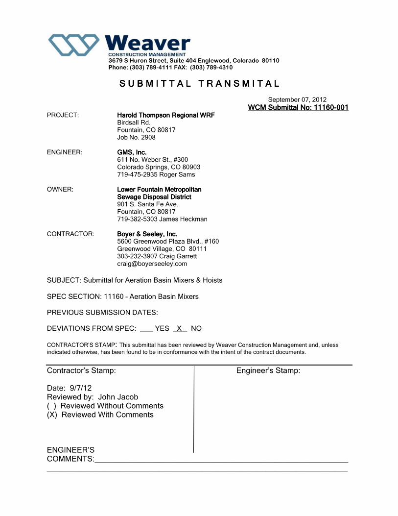
3679 S Huron Street, Suite 404 Englewood, Colorado 80110
Phone: (303) 789-4111 FAX: (303) 789-4310
S U B M I TS U B M I TS U B M I TS U B M I T TTTT A L T R A N S M I T A LA L T R A N S M I T A LA L T R A N S M I T A LA L T R A N S M I T A L
September 07, 2012
WCWCWCWCMMMM Submittal Submittal Submittal Submittal NNNNoooo: : : : 11111111160160160160----000000001111 PROJECT: Harold ThompHarold ThompHarold ThompHarold Thompson son son son Regional Regional Regional Regional WRFWRFWRFWRF
Birdsall Rd. Fountain, CO 80817 Job No. 2908
ENGINEER: GMS, Inc.GMS, Inc.GMS, Inc.GMS, Inc. 611 No. Weber St., #300 Colorado Springs, CO 80903 719-475-2935 Roger Sams
OWNER: Lower Fountain Metropolitan Lower Fountain Metropolitan Lower Fountain Metropolitan Lower Fountain Metropolitan Sewage Disposal DistrictSewage Disposal DistrictSewage Disposal DistrictSewage Disposal District 901 S. Santa Fe Ave. Fountain, CO 80817 719-382-5303 James Heckman
CONTRACTOR: Boyer & Seeley, Inc.Boyer & Seeley, Inc.Boyer & Seeley, Inc.Boyer & Seeley, Inc. 5600 Greenwood Plaza Blvd., #160 Greenwood Village, CO 80111 303-232-3907 Craig Garrett [email protected]
SUBJECT: Submittal for Aeration Basin Mixers & Hoists
SPEC SECTION: 11160 – Aeration Basin Mixers PREVIOUS SUBMISSION DATES: DEVIATIONS FROM SPEC: YES X NO
CONTRACTOR’S STAMP: This submittal has been reviewed by Weaver Construction Management and, unless
indicated otherwise, has been found to be in conformance with the intent of the contract documents.
Contractor’s Stamp: Engineer’s Stamp: Date: 9/7/12 Reviewed by: John Jacob ( ) Reviewed Without Comments (X) Reviewed With Comments ENGINEER’S COMMENTS:_________________________________________________________________________________________________________________________________

PH 303-789-4111 3679 So. Huron St., Suite 404
FX 303-789-4310 Englewood, Colorado 80110
A S U B S I D I A R Y O F G A R N E Y C O N S T R U C T I O N weavercm.com
Project: HDTWRF Submittal No.: 11160-001
Location: Fountain, CO
Supplier: Boyer Seeley
Date: 9/7/12
Submittal 11160-001 Aeration Basin Mixers and Hoists
Additional Submittal Review Comments:
1. It appears Boyer Seeley did not include the responses to questions 1 to 10 in the Mixer Mast/SRP Guide
Rail Inquiry Form, attached. Boyer Seeley shall incorporate all responses in a re-submittal.
2. The Memorandum list model AMG 150.73.354 while the submittal references model 150.29.408.6.1P.
Also refer to Grundfos Inquiry Form question and response #1. Boyer Seeley shall confirm that the
submitted mixer model is an equal to the one listed in the Memorandum.
3. Memorandum dated 7/23/12 minimum mixer pumping capacity 1,200 GPM. Please confirm minimum
pumping capacity. One of the cut sheets in the submittal references Primary Flow GPM 11,782.
4. Memorandum dated 7/23/12 requires each mixer have a NEMA 3R disconnect for mounting to the
handrail. The submittal includes drawing Mixer-2_ABB Titled 5 HP Mixer Controller Detail. The proposed
mixers are 15 HP. Please ensure the HP rating for each panel is properly sized for a 15 HP motor.
Connection of the panel to the handrail by Electrical Subcontractor.
5. The submittal contains a cut sheet labeled Series M Mixer Mast which appears to be a general diagram of
a mast and does not appear to be applicable to this project. Boyer Seeley to confirm.
6. Regarding sheet labeled Series M Stainless Steel Mixer Mast Assembly Quantity 10. The drawing shows
the upper extension at or near the top of the wall. Referring to Sheet 1/AB-13 provided in the
Memorandum, the air pipe and walkway may interfere with the upper extensions at the 10 locations.
WCM suggest lowering the upper arm extensions at least 6 to 8 inches below top of wall to avoid any
conflict. Input request by GMS. Also, the pivot point of the extension is 22” from the wall. At this
distance the pivot point would be ‘under’ the 12 inch air header. WCM does not see an issue with this.
GMS to confirm.
7. Regarding sheet labeled Series DM Fixed Reach Portable Hoist. The hoist length is 60 inches plus 6 ½
inches of mast per the mast assembly sheets equals a total of 66 ½ inches. The hand rail is 42 inches tall
leaving 24 1 /2 inches to maneuver the mixer over the handrail. It appears based on the AMG Gear Drive

PH 303-789-4111 3679 So. Huron St., Suite 404
FX 303-789-4310 Englewood, Colorado 80110
A S U B S I D I A R Y O F G A R N E Y C O N S T R U C T I O N weavercm.com
Mixer Data Sheet that the longest length of the mixer is 18 1/16 inches which will allow the mixer to fit
over the rail.
8. Boyer Seeley shall provide a lever arm to allow for full rotation of the column. This information is not
mentioned in the submittal.
9. The submittal includes information about Warranty. The Warranty is per the executed Purchase
Agreement between WCM and Boyer Seeley.
10. Boyer Seeley has requested the following clarification from GMS. Clarify if the requirement for a soft
start in the control is needed. Boyer Seeley does not need this and for a 15 Hp mixer this would be
very unusual. Please note this clarification. If absolutely required - go to the control for the AFG.
End of Review

BE > THINK > INNOVATE >
Tim Tressler * 372 Charlton Lane - Tappahannock, VA 22560 Phone: 630-536-7288 Email: [email protected]
MIXER MAST / SRP GUIDE RAIL INQUIRY FORM
To effectively provide accurate submittal drawings for Mixer, SPR, and
mixer mast installations, please complete the following questions. In
addition, please provide a sectional drawing detail of the location where
the mixer / SRP will be installed.
1. Project Name: Harold D. Thompson Regional WRF – Weaver
Construction Management
2. Mixer / SRP Models (s): AMG.150.29.408.6.1P Is this an equivalent to
the model AMG.150.73.354 specified in the Mixer Memorandum dated
07-23-12? Is the second number the propeller diameter? If so, “ .29.”
is less than half the specified “.73”, will the flow generated by these
two be similar or not?
3. Quantity: 12 12 mixers, 12 masts, see question no. 10 for hoists
4. Mixer locations(s) – this facilitates tagging of the submittal drawings
for individual masts at specific locations: ____per sheet AB-11______
I have added tag nos. to the mixers to AB-11, see attached
5. Overall tank depth / top of walkway surface to basin floor: [Top of
walkway is 5413.38 per sheet 1/AB-13] – YES [and top of concrete
slope is 5386.41 per sheet 1/AB-13.] – NO, a-basin floor slope = 0.50%
from West to East. Basin floor elev. = 5386.20 (West end), = 5385.41
(East end)______
6. Will the upper mast / guide rail bracket be mounted to a concrete
deck or metal walkway: Neither. Attach to concrete wall per sheet
1/AB-13. Supports shall be designed by mixer manufacture as per the
notes on sheet 1/AB-13._________

BE > THINK > INNOVATE >
Tim Tressler * 372 Charlton Lane - Tappahannock, VA 22560 Phone: 630-536-7288 Email: [email protected]
7. If applicable, what is the offset or overhang dimension. This is the
difference between the surface where the upper bracket will be
mounted and the tank wall below the overhang: There will be no
overhang since the upper bracket must mount to the inside face of
basin wall below the walkway. Edge of walkway will overhang inside
face of basin wall by 6” and edge of support angles under walkway
will overhang inside face of basin wall by 12”. However, neither of
these items can be used for attachment of a mixer/mast support.
8. Will the mast / guide rail be mounted in an open tank or below an
access cover: __Open______
9. Specify if the mast / guide rail is to be Type 304 or Type 316 SS: 304
10. Are hoists required? Yes If so how many: 12 If all masts AND
hoists are fixed units then 12 hoists will be required. If the masts are
fixed in place and a removable or portable hoist can be furnished,
then only one hoist can be supplied and the operators will move it
into the different locations as necessary.

SUBMITTAL DOCUMENTATION
Submersible Gear Drive Mixers
SERIES
TYPE/SIZE MOTOR MATERIAL
PROPELLER
AMG 150.29.408.6.1P 15 Hp, 1750 rpm CI/SS 316 SS / 408 rpm
MANUFACTURER
GRUNDFOS
3905 Enterprise Court Aurora, IL 60598-0620 Phone (630) 236-5500
Fax (630) 236-5511
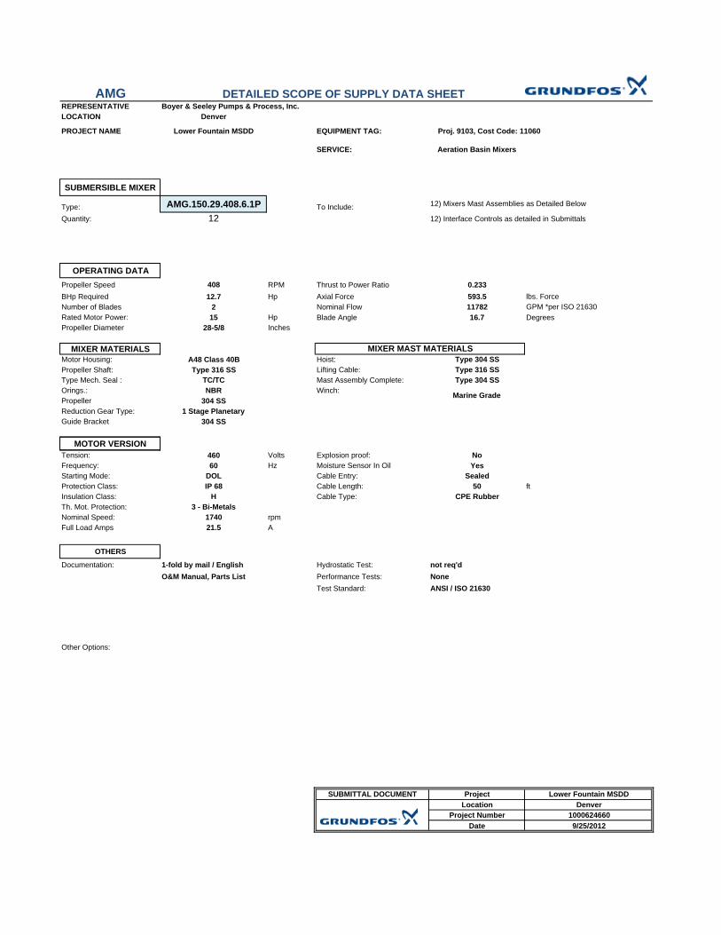
AMGREPRESENTATIVE Boyer & Seeley Pumps & Process, Inc.LOCATION Denver
PROJECT NAME Lower Fountain MSDD EQUIPMENT TAG: Proj. 9103, Cost Code: 11060
SERVICE: Aeration Basin Mixers
SUBMERSIBLE MIXER
Type: AMG.150.29.408.6.1P To Include:Quantity: 12
OPERATING DATAPropeller Speed 408 RPM Thrust to Power Ratio 0.233BHp Required 12.7 Hp Axial Force 593.5 lbs. ForceNumber of Blades 2 Nominal Flow 11782 GPM *per ISO 21630Rated Motor Power: 15 Hp Blade Angle 16.7 DegreesPropeller Diameter 28-5/8 Inches
MIXER MATERIALSMotor Housing: A48 Class 40B Hoist: Type 304 SSPropeller Shaft: Type 316 SS Lifting Cable: Type 316 SSType Mech. Seal : TC/TC Mast Assembly Complete: Type 304 SSOrings.: NBR Winch:Propeller 304 SSReduction Gear Type: 1 Stage PlanetaryGuide Bracket 304 SS
12) Interface Controls as detailed in Submittals
DETAILED SCOPE OF SUPPLY DATA SHEET
12) Mixers Mast Assemblies as Detailed Below
MIXER MAST MATERIALS
Marine Grade
MOTOR VERSIONTension: 460 Volts Explosion proof: NoFrequency: 60 Hz Moisture Sensor In Oil YesStarting Mode: DOL Cable Entry: SealedProtection Class: IP 68 Cable Length: 50 ftInsulation Class: H Cable Type: CPE RubberTh. Mot. Protection: 3 - Bi-MetalsNominal Speed: 1740 rpmFull Load Amps 21.5 A
OTHERS
Documentation: 1-fold by mail / English Hydrostatic Test:O&M Manual, Parts List Performance Tests:
Test Standard:
Other Options:
SUBMITTAL DOCUMENT Project Lower Fountain MSDDLocation Denver
Project Number 1000624660Date 9/25/2012
not req'dNoneANSI / ISO 21630

AMG GEAR DRIVE MIXER DATA SHEET
DIMENSIONS - Inches
A B C D E * Net Weight
39-7/8 10-9/16 16-7/8 18-1/16 28-5/8 390
AMG.150.29.408.6.1P
* - lbs. includes mixer, motor bracket, 30 ft. power/control cable
PHYSICAL DATA
Motor rpm Propeller rpm
Axial Thrust
lbs. Force
Axial Thrust N
Max Install Depth
*Primary Flow GPM
Mean Flow Velocity ft./sec.
1740 408 593.5 2640 65 ft. 11782 5.84*Note: Flow Data Ascertained per ISO 21630 Standards
Other Methodology Available on RequestELECTRICAL DATA
Rated Hp Input Hp Shaft Hp Voltage FLA Start Amps Power Factor
15 15.1 12.7 460 21.5 115 0.81
MATERIALS
Motor Housing Propeller Seals Fasteners Mounting
BracketMotor Shaft
Propeller Shaft
CI 40B 316 SS SIC/SIC 316 SS 316 SS AISI 4820 316 SS

8
Product description Mixers and flowmakers
ShaftsAMD, AMG and AFG motor and gear shafts are made of stainless steel. See table below.
PropellerFor the number of propeller blades on the various types of mixers and flowmakers, see section Technical data, page 46.
Power supply cablesThe specific cable can be found in the tables in section Technical data, page 46.
Cable entryElastomer 70 Shore-hardness.
SensorsAs standard, the pump is supplied with the following:
• For AMD & AMG three bi-metallic thermal switches (PTO), one in each motor winding
• one water-in-oil sensor
Wiring diagrams
Fig. 7Wiring diagram for AMD & AMG
Fig. 8 Wiring diagram, three thermistors - for AFG only
ShaftAMD AMG, AFG
DIN AISI DIN AISIMotor 1.4401 316 1.7147 5120Gear 1.4401 316 1.5713 3115
Cable type DimensionOuter
diameter[Inches]
StandardS1BN8-F 11G1.5 11 x 1.5 mm2 3/4S1BN8-F 11G2.5 11 x 2.5 mm2 7/8H07RN-F 7G4 + 4 x 1 7 x 4 mm2 + 4 x 1 mm2 7/8
BiogasPower supply cable Lapp Ölflex FD Robust 7 x 4 mm2 + 4 x 1.5 mm2 7/8
Screened cableH07RC4N8-F 7G4 + 4 x 1 7 x 4 mm2 + 4 x 1 mm2 15/16
TM02
494
0 20
02
Terminals Description
1, 2, 3, 4, 5, 6 Ends of the three stator windings (U1, U2, V1, V2, W1, W2)
11, 12 Thermal switches (F6)
21, 22 Leak sensor in gearbox (B)See section Water-in-oil sensor, page 9.
TM02
493
2 20
02
Terminals Description
1, 2, 3, 4, 5, 6 Ends of the three stator windings (U1, U2, V1, V2, W1, W2)
31, 32 Thermistors (according to DIN 44081) (ϑ1, ϑ2, ϑ3)
21, 22 Leak sensor in gearboxSee section Water-in-oil sensor, page 9.
B
LSV2U2W2W1V1U1 PEPTO
LSV2U2V1U1 W2W1 PTC PE


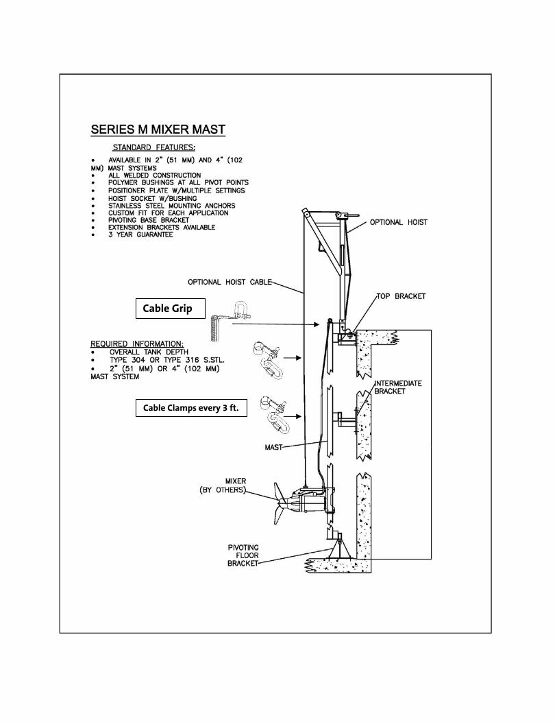
Cable Clamps every 3 ft.
Cable Grip


Mixers & Flowmakers Grundfos Chicago Corporation PHONE: (630) 236‐5500 3905 Enterprise Court FAX: (630) 236‐5511 Aurora, Illinois 60504 Web: www.yccpump.com
Standard 2‐Year Warranty for Municipal Applications Grundfos Series AMG, AMD, & AMF
For a period of twenty‐four (24) months from start‐up or thirty (30) months from shipment, whichever occurs first, Yeomans Chicago Corporation warrants that the equipment covered by this order shall be free of defects in materials and workmanship under normal use and service, and when properly installed. YCC agrees to repair or replace F.O.B. point of shipment, such equipment, or any part thereof, previously furnished by YCC as actually found, after inspection, as defective, provided: (a) said equipment has been properly installed, operated and maintained by Buyer in accordance with YCC's recommendations and specifications, and (b) Buyer notifies YCC, in writing within thirty (30) days from when such defect becomes apparent. Unless agreed to the contrary by YCC in writing, any work done, material furnished, repairs or designs made by “others” than specifically approved by YCC, shall void the warranty. Equipment that is repaired/replaced is warranted for the residual period of the initial warranty. The mixer/flowmaker has a mechanical and a rotary shaft seal with a moisture detection system. The warranty shall cover the cost of replacement of those seals only. IF THE MOISTURE DETECTION SYSTEM IS NOT CONNECTED, THE WARRANTY IS VOID! If the mixer/flowmaker is approved for installation without a moisture detection system, the machine must be physically inspected for leakage every six months. WITHOUT PROOF OF THIS INSPECTION HAVING BEEN DONE, THE WARRANTY IS VOID. The mixer/flowmaker motor has winding thermostats. The thermostats must be connected per local, state and/or National Electric Code. IF THE MOTOR WINDING THERMOSTATS ARE NOT CONNECTED, THE WARRANTY IS VOID! Equipment destined for long‐term storage shall be stored in accordance with the appropriate O&M instructions. Any damage to the equipment due to improper storage conditions shall void this warranty. Equipment not manufactured by Grundfos/YCC, such as starting equipment, electrical apparatus and other peripheral items are covered by the warranty of the respective manufacturer in lieu of the above. YCC shall not be liable for incidental or consequential losses, damages or expenses, directly or indirectly arising from the sale, handling or use of the equipment, or from any other cause relating thereto, and YCC’s liability hereunder in any case is expressly limited to the replacement (in the form originally shipped) of equipment or any part thereof, not complying with this order, or, at YCC's election, to the repayment of, or crediting Buyer with an amount equal to the purchase price of such equipment, whether such claims are for breach or warranty or negligence.
THIS WARRANTY IS EXPRESSLY MADE IN LIEU OF ANY AND ALL OTHER WARRANTIES EXPRESSED OR IMPLIED INCLUDING WARRANTIES OF MERCHANTABILITY AND FITNESS.
mixer_flowmaker_warranty.doc Rev 02/01/2011
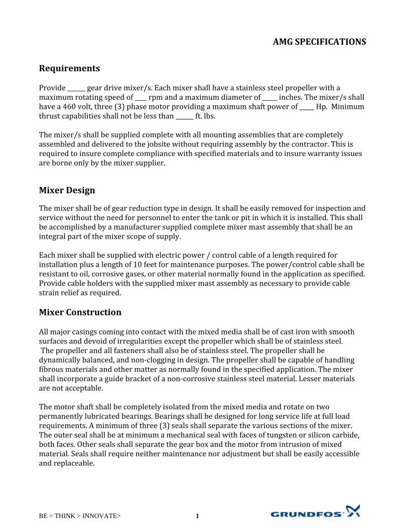
BE > THINK > INNOVATE> 1
AMG SPECIFICATIONS Requirements Provide ______ gear drive mixer/s. Each mixer shall have a stainless steel propeller with a maximum rotating speed of ____ rpm and a maximum diameter of _____ inches. The mixer/s shall have a 460 volt, three (3) phase motor providing a maximum shaft power of _____ Hp. Minimum thrust capabilities shall not be less than ______ ft. lbs. The mixer/s shall be supplied complete with all mounting assemblies that are completely assembled and delivered to the jobsite without requiring assembly by the contractor. This is required to insure complete compliance with specified materials and to insure warranty issues are borne only by the mixer supplier.
Mixer Design The mixer shall be of gear reduction type in design. It shall be easily removed for inspection and service without the need for personnel to enter the tank or pit in which it is installed. This shall be accomplished by a manufacturer supplied complete mixer mast assembly that shall be an integral part of the mixer scope of supply. Each mixer shall be supplied with electric power / control cable of a length required for installation plus a length of 10 feet for maintenance purposes. The power/control cable shall be resistant to oil, corrosive gases, or other material normally found in the application as specified. Provide cable holders with the supplied mixer mast assembly as necessary to provide cable strain relief as required. Mixer Construction All major casings coming into contact with the mixed media shall be of cast iron with smooth surfaces and devoid of irregularities except the propeller which shall be of stainless steel. The propeller and all fasteners shall also be of stainless steel. The propeller shall be dynamically balanced, and non‐clogging in design. The propeller shall be capable of handling fibrous materials and other matter as normally found in the specified application. The mixer shall incorporate a guide bracket of a non‐corrosive stainless steel material. Lesser materials are not acceptable. The motor shaft shall be completely isolated from the mixed media and rotate on two permanently lubricated bearings. Bearings shall be designed for long service life at full load requirements. A minimum of three (3) seals shall separate the various sections of the mixer. The outer seal shall be at minimum a mechanical seal with faces of tungsten or silicon carbide, both faces. Other seals shall separate the gear box and the motor from intrusion of mixed material. Seals shall require neither maintenance nor adjustment but shall be easily accessible and replaceable.

BE > THINK > INNOVATE> 2
Date: 2011 – 01‐01 Mixer Motor Motors shall be provided as an integral part of the mixer design. Motors shall be suitable and fully capable of operation with PWM variable frequency drives and shall be non‐overloading across the full performance range of the mixer. The motors service factor shall be at minimum 1.15 and be capable of at minimum 20 starts per hour. Motors shall be capable of withstanding all forces which may be imposed during the course of normal operation and be asynchronous in design. Gearbox
The mixer shall have a single stage planetary reduction gear to allow optimization of propeller rotational speeds. All bearings within the reduction gear, as well as all other bearings, shall have a minimum L10 life of 100,000 hrs. The gear box shall be provided with a “water‐in‐oil” leakage sensor to allow operations personnel to monitor intrusions of water into the gear box proper, without having to remove the mixer from service. Direct Drive mixers that do not utilize a gear reduction unit in their design shall not be acceptable. Protection The mixer motor shall be furnished with protective devices as normally provided by the pump manufacturer. These devices shall be monitored by a manufacturer supplied relay status module. The motor shall be provided with thermal sensors embedded in each winding to provide motor over‐temperature protection. A water‐in‐oil leakage sensor shall be installed within the oil chamber to monitor the amount of water in the oil. In this way, operations personnel can monitor seal leakage without having to remove the mixer from service. Mixer Mast Assembly
Each mixer shall be supplied with its own mixer mast assembly per contract drawings. A removable turning handle shall be provided for each mast to permit manual adjustment of the mixer’s horizontal attitude. The mast shall be minimum 4” x 4” square tube with 1/8” wall, supplied with factory welded sockets at the top, bottom and at intermediate levels as needed to provide support at a maximum of 10ft intervals. Sockets shall be lined with a kynar® insert to insure easy mast rotation, and shall work in conjunction with supplied mounting brackets to secure the unit to the tank wall. The top mast bracket shall include a rotary positioning plate which allows the mast to be secured in any of 14 locations with a total of 167 degrees of rotation. Wall extension brackets, if required, shall be provided with the mast and shall be custom designed to insure a straight and true installation. A fabricated mixer support frame (an integral part of the mixer and guide mast assembly system) shall support the entire weight of the mixer at its horizontal center of gravity. The
Date: 2011‐01‐01

BE > THINK > INNOVATE> 3
frame shall include a bracket with stainless steel or nylon liners for attachment to the mast. A static cable with adjustable end loop shall be furnished to support the mixer at various operating levels; as‐well‐as; a permanently mounted stop on the mixer mast to insure the mixer cannot be operated to a level below which improper or damaging operation could occur. Portable Lifting Hoist and Lifting Cable Each mixer mast assembly shall be provided with one (1) portable hoist with a fixed reach for each mixer in this section. The hoist shall be designed to be mounted on the top mast mounting bracket. It shall include a manual brake winch, and shall be adequately rated to lift the mixer and support arm off the mast and directly onto the adjacent deck surface. If handrail is fitted to the deck, removable sections or safety chain sections shall be provided such that the mixer does not need to be lifted over the handrail. A Type 316 stainless steel lifting cable, permanently attached to each mixer, shall be provided in sufficient length for attachment of the upper end to the winch cable reel when the davit assembly is installed. Quality Control
Prior to shipment, the mixer manufacturer shall check each unit for proper balance and alignment, quiet vibration‐free operation, proper electrical characteristics, and satisfactory performance. The mixer manufacturer shall perform certified performance tests in accordance with ANSI/ISO Standards to insure that the performance of the supplied units is in accordance with specified requirements. These tests results shall be certified by the mixer manufacturer and submitted to the engineer for approval prior to shipment. The engineer and owner reserve the right to inspect these tests. Verification of Performance All mixers shall be field tested after installation to demonstrate satisfactory operation without excessive noise, vibration, or overheating. Any mixer which fails to meet any of the contract specifications will be modified, repaired or replaced by the contractor at no additional cost to the owner.
Date: 2011‐01‐01

keep your processes moving
GruNDFos amg, amd, and afg rangesMixers and flowmakers, 0.75 - 18.5 kW
60 Hz DIN
Mixers and flowmakers for wastewater and sludge applications

Innovative bracket designBracket design optimized for easy installation – adaptable for many different applications with no need for customisation.
motor housingstainless steel AIsI 316; smooth, self-cleaning surface.
Protection ringpoM protection ring prevents fibres from snagging on the propeller shaft.
self-cleaning propellerHydrodynamic 3-blade propeller and hub with excellent self- cleaning capabilities, made from stainless steel AIsI 316.
Two ball bearingsThe rotor shaft rests on two heavy-duty ball bearings, absorbing forces from all directions.
motor protectionThe motor is protected against overload and overheating by three thermal switches placed in each motor winding.
active electronic leak sensorLiquid detection system prevents damage if water should penetrate into the oil chamber.
Triple sealing systemThe mechanical shaft seal is protected by an innovative triple sealing system for maximum reliability and durability. Find design details online.
Watertight cable entryA watertight cable entry point with self-shaping seal prevents cable damage.
motor protectionThe motor is protected against over-load and overheating by three thermal switches or three thermistors placed in each motor winding.
Planetary gearThe gear housing has a slim design for optimal hydro-dynamic properties.
Triple sealing systemAn ingenious triple seal system protects the mechanical shaft seal, minimising wear and service requirements.
flexible motor bracketAllowing for top or bottom fixation, this motor bracket is designed for easy installation in almost any setting and promotes stable operation.
active electronic leak detector Indicates possible liquid in the gear housing. even the smallest quantity of liquid in the gear housing is quickly detected, allowing ample time for service before any damage is done.
Two ball bearingsThe rotor shaft rests on two ball bearings, which accommodateboth axial and radial forces.
Choice of propellersHydrodynamic 2 or 3-blade propellers help ensure high efficiency and non-clogging operation. The propeller hub forms a labyrinth seal for the sealing system.
amg/afg
amd
Mixers and flowmakers make sure that particles remain evenly distributed in wastewater and sludge, preventing sed-imentation and supporting treatment processes.
The range covers everything from small-scale mixers, ideal for prefabricated pumping stations, to large-scale flowmak-ers created for large tanks and basins. Wastewater infrastruc-ture is an obvious application area – from network stations to treatment plants – but the mixing power of the AMD, AMG, and AFG ranges is also appreciated by industries and agricul-tural professionals worldwide.
Typical application areasSewage pumping stations•Wastewater treatment plants•Industrial processes•Agriculture •
Installation Great care has been taken to ensure easy installation of the Grundfos mixer/flowmaker ranges. The mounting bracket has been optimised on the basis of installer and customer input; for example, top/bottom fixation capabilities make the units instantly suitable for a very wide range of applications. Different control options are available to match your system – from start/stop to more sophisticated functions. Ask us for more.
A complete range of installation accessories is available for all models. For full details, visit Grundfos WebcAps online.
STIRRING SUPPORT FOR YOUR SYSTEMS Mixers and flowmakers. Creating flows on any scale.
Grundfos is dedicated to making wastewater systems of any kind as reliable and efficient as possible. Our AMD, AMG, and AFG ranges reflect this dedication. Very dependable and highly efficient, these submersible mixers and flowmakers prevent sedimentation and sup-port processes in treatment plants, industries, and agriculture.
All models share many features, facilitating easy maintenance. Materials are selected for strength, and every component is tested for durability before assembly. Recent evolutions include a tri-ple sealing system for maximum protection of the mechanical shaft seal as well as an installa-tion-friendly bracket.
Grundfos mixers are available with direct (AMD) or planetary gear-driven (AMG) stainless steel or polyamide propellers. All flowmakers (AFG) are gear-driven and share the AMG motor design.
• AMD (direct-driven) mixers are available in8-pole versions in range from 1,5-4,5kW
• AMG (gear-driven)mixers are available from1.5-18.5 kW.
• AFGflowmakersareavailablefrom1.3-7.5kW.
When you design your systems, we invite you to draw on the Grundfos fount of experience. our application specialists can help ensure the right flow characteristics, velocities, etc. you may well find that Grundfos’ recommendations can save you substantial sums on construction. To make the most of our help, we urge you to call us at the earliest stage possible.
ThE AMD, AMG, AND AFG AT wORk
Mixers are ideal for pre-venting sedimentation in small-scale pumping stations.
Flowmakers can create the flow and velocities you require. For best results, ask us for design assistance.
MIxER AND FlOwMAkER FEATURES– and what they do for you

Being responsible is our foundationThinking ahead makes it possible
Innovation is the essence
9775
0023
101
0 \
9996
\ C
orpo
rate
Bra
ndin
g \
grundfos a/sPoul Due Jensens Vej 7DK-8850 BjerringbroTel: +45 87 50 14 00
www.grundfos.comThe name Grundfos, the Grundfos logo, and the payoff Be–Think–Innovate are registrated trademarks owned by Grundfos Management A/S or Grundfos A/S, Denmark. All rights reserved worldwide.
see The bIgger PICTureGrundfos is a global leader within water handling technology. our passion is to bring you all the products you require to create and operate pump systems that combine reliability, cost-effi-ciency – and innovation. our products are for use in water supply and wastewater infrastructure on any scale.
Grundfos has a full line of products and systems for the intake, treatment and distribution of drinking water and for the trans-port and treatment of wastewater. We also offer expertise and industry insight that can increase reliability and reduce lifecycle costs for water utilities.
key product areas include:
submersible pumps
surface pumps
sewage pumps
Mixers, flowmakers & recirculation pumps
pumping stations
Monitoring & controls
Dosing & disinfection
Aeration equipment
our products are the result of decades of engineering expertise. supported by a worldwide service network. Visit www.grundfos.com/water-utility for more.

G:\L
FMS
DD
\201
66\3
62\A
B11
\AB
11.d
wg,
AB
11, 9
/5/2
012
3:59
:03
PM
, mam
, DW
G T
o P
DF.
pc3,
1:1