sil-safety instructions pressure-transmitter 2600t …...periodic checks sm/261/sil-en rev. 02...
TRANSCRIPT

SIL-Safety Instructions SM/261/SIL-EN Rev. 02
Pressure-Transmitter 2600TModels 261Gx, 261Ax
Pos: 1 /Titelblätter / Copyright/SIL/Druck/Druckmessumformer/261Gx, 261Ax @ 12\mod_1187247839437_3101.doc @ 115416
Model 261GS/GC/GM/GG/GJ/GN/GR/GxModel 261AS/AC/AM/AG/AJ/AN/AR/Ax
Instructions for Functional Safety
Pos: 2 /======= Seitenumbruch ======== @ 0\mod_1126532365768_3101.doc @ 3830
Blinder Text
2 Models 261Gx, 261Ax SM/261/SIL-EN Rev. 02
Pos: 3 /Titelblätter / Copyright/Copyright-Seite @ 0\mod_1138781938968_3101.doc @ 3122
Pressure-Transmitter 2600T
Models 261Gx, 261Ax
SIL-Safety Instructions SM/261/SIL-EN Rev. 02
01.2008
Manufacturer: ABB Automation Products GmbH Schillerstraße 72 32425 Minden Germany Tel.: +49 551 905-534 Fax: +49 551 905-555 [email protected]
© Copyright 2008 by ABB Automation Products GmbH Subject to change without notice
This document is protected by copyright. It assists the user with the safe and efficient operation of the device. The contents may not be copied or reproduced in whole or in excerpts without prior approval of the copyright holder.
Pos: 4 /Inhaltsverzeichnis/Inhaltsverzeichnis für alle Dokumente @ 0\mod_1138710310890_3101.doc @ 3129 Contents
Contents
SM/261/SIL-EN Rev. 02 Models 261Gx, 261Ax 3
1 Field of Application .............................................................................................................................................4 2 Acronyms and abbreviations .............................................................................................................................4 3 Relevant standards .............................................................................................................................................5 4 Terms and definitions .........................................................................................................................................5 5 Safety function.....................................................................................................................................................6 6 Applicable device documentation .....................................................................................................................7 7 Periodic checks ...................................................................................................................................................8 8 Configuration .....................................................................................................................................................10 9 Characteristics for functional safety ...............................................................................................................15 10 Appendix ............................................................................................................................................................16 11 Management summary......................................................................................................................................17 12 Declaration of conformity.................................................................................................................................19

Field of Application
4 Models 261Gx, 261Ax SM/261/SIL-EN Rev. 02
Pos: 5 /Überschriften/1/A - C/Anwendungsbereich @ 1\mod_1146730389234_3101.doc @ 8296
1 Field of Application Pos: 6 /SIL Handbücher/Druck/261Gx, 261Ax/Verwendungsbereiche Druckumformer 2600T @ 1\mod_1146731099156_3101.doc @ 8330
Absolute or gauge pressure measurement that shall meet the safety requirements according to IEC 61508.
The operative limits are described in the Data Sheet SS/261GS/AS.
Pos: 7 /Überschriften/1/A - C/Akronyme und Abkürzungen @ 1\mod_1146731222953_3101.doc @ 8338
2 Acronyms and abbreviations Pos: 8 /SIL Handbücher/Druck/261Gx, 261Ax/Akronyme und Abkürzungen @ 1\mod_1146731320281_3101.doc @ 8343
Acronym /
Abbreviation
Designation Description
HFT Hardware Fault Tolerance
The hardware fault tolerance of the device.
This is the capability of a functional unit to continue the execution of the demanded function in case of faults or deviations.
MTBF Mean Time Between Failures
This is the mean time period between two failures.
MTTR Mean Time To Repair
This is the mean time period between the occurrence of a failure in a device or system and its repair.
PFD Probability of Failure on Demand
This is the likelihood of dangerous safety function failures occurring on demand.
PFDAVG Average Probability of Failure on Demand
This is the average likelihood of dangerous safety function failures occurring on demand.
SIL Safety Integrity Level
The international standard IEC 61508 specifies four discrete safety integrity levels (SIL 1 to SIL 4). Each level corresponds to a specific probability range regarding the failure of a safety function. The higher the safety integrity level of the safety-related systems, the lower likelihood of non-execution of the demanded safety functions.
SFF Safe Failure Fraction
The fraction of non-hazardous failures, i.e. the fraction of failures without the potential to set the safety-related system to a dangerous or impermissible state.
Low demand mode
Low demand mode of operation
Measuring mode with low demand rate. Measuring mode, in which the demand rate for the safety-related system is not more than once a year and is not greater than double the frequency of the periodic test.
DCS Distributed Control System
Control systems that are used in industrial engineering applications to monitor and control distributed equipment.

Relevant standards
SM/261/SIL-EN Rev. 02 Models 261Gx, 261Ax 5
Acronym /
Abbreviation
Designation Description
HMI Human Machine Interface
Here, the HMI is the combined module consisting of LCD and local keypad.
DTM Device Type Manager
The DTM is a software module that provides functions for accessing device parameters, configuring and operating the devices and diagnosing problems. By itself, a DTM is not executable software. It only 'comes to life' in an so called FDT 'container' program.
LRV Device Configuration
Lower Range Value of the measurement range
URV Device Configuration
Upper Range Value of the measurement range
Multidrop Multidrop mode In multidrop mode, up to 15 field devices are connected in parallel to a single wire pair. The analog current signal serves just to energize the two-wire devices providing a fixed current of 4mA.
Pos: 9 /Überschriften/1/G - I/Geltende Normen @ 1\mod_1146731568625_3101.doc @ 8352
3 Relevant standards Pos: 10 /SIL Handbücher/Druck/261Gx, 261Ax/Geltende Normen @ 1\mod_1146731634937_3101.doc @ 8357
Standard Designation
IEC 61508, Part 1 to 7 Functional safety of electrical/electronic/programmable electronic safety-related systems
Pos: 11 /Überschriften/1/A - C/Begriffe und Definitionen @ 1\mod_1146731780265_3101.doc @ 8366
4 Terms and definitions Pos: 12 /SIL Handbücher/Druck/261Gx, 261Ax/Begriffe und Definitionen @ 1\mod_1146731860265_3101.doc @ 8371
Terms Definitions
Dangerous failure Failure with the potential to set the safety-related system to a dangerous or inoperative state.
Safety-related system A safety-related system carries out the safety functions needed to establish or maintain a safe state e.g. in a plant.
Example: A pressure gauge, a logic unit (e.g. limit signal transmitter) and a valve form a safety-related system.
Safety function A defined function carried out by a safety-related system in order to establish or maintain a safe state of the plant under consideration of a specified dangerous incident. Example: Pressure limit monitoring
Pos: 13 /======= Seitenumbruch ======== @ 0\mod_1126532365768_3101.doc @ 3830

Safety function
6 Models 261Gx, 261Ax SM/261/SIL-EN Rev. 02
Pos: 14 /Überschriften/1/S - U/Sicherheitsfunktion @ 1\mod_1146732234250_3101.doc @ 8380
5 Safety function Pos: 15 /SIL Handbücher/Druck/261Gx, 261Ax/Sicherheitsfunktion @ 12\mod_1187164875281_3101.doc @ 115282
The transmitters 261G / 261A produces an analog signal (4 ... 20 mA) proportional to the absolute or gauge pressure. All safety functions exclusively refer to this output.
The total valid range of the output signal shall be configured to a minimum of 3.8 mA and a maximum of 20.5 mA (Factory Default).
Alarm response and current output
In case of detected critical faults the configured alarm current will be produced - this is fed to a subsequent logic unit, e.g. a DCS and monitored for violation of a defined maximum value. There are two selectable modes for this alarm current:
• HIGH ALARM (Max Alarm current) which is the factory default setting
• LOW ALARM (Min Alarm current)
The low alarm current is configurable from 3.5 to 4.0 mA with a factory default setting to 3.5 mA.
The high alarm current is configurable from 20.0 mA to 23.6 mA with a factory default setting 21 mA.
In the following cases a detected failure will be signaled within the LOW ALARM range independent from the configured alarm current:
• Program execution error
• Memory Error (Non Volatile Data, RAM, ROM)
Warning!
For a safe fault monitoring the following conditions must be fulfilled:
• The LOW ALARM must be configured with a value ≤ 3.6 mA.
• The HIGH ALARM must be configured with a value ≥ 21 mA.
• The DCS must be capable of recognizing the configured High Alarms or Low Alarms as a malfunction detection.
Warning!
For a safe current output operation the terminal voltage at the device must be given from 11 V DC to 42 V DC.
The DCS loop must be capable to provide the required voltage level even if the current output operates on the configured HIGH ALARM.
The device is not safety compliant during the following conditions:
• During Configuration
• If the HART Multidrop mode is activated
• During Simulation
• During Test of the safety function

Applicable device documentation
SM/261/SIL-EN Rev. 02 Models 261Gx, 261Ax 7
Warning!
The safety function of the devices includes the basic device with main electronics, sensor electronics and sensor through to the sensor diaphragm and directly fitted process connection and remote seals respectively.
The fraction of failures without the potential to put the device into a dangerous function status is given by the SFF value shown in chapter 9 “Characteristics for functional safety”.
Total Safety Accuracy
The defined value for the “Total Safety Accuracy“ of the safety function of this device is:
±2 % of URL (Upper Range Limit)
See appropriate Data Sheet SS/261GS/AS, SS/261GC/AC or SS/261GR/AR for the base accuracy specifications of this device.
Turn on time
After a power-up of the device, the signal can be considered to be safe after 2 minutes.
Pos: 16 /Überschriften/1/M - O/Mitgeltende Gerätedokumentationen @ 1\mod_1146733068781_3101.doc @ 8394
6 Applicable device documentation Pos: 17 /SIL Handbücher/Druck/261Gx, 261Ax/Mitgeltende Gerätedokumentationen @ 12\mod_1187164904515_3101.doc @ 115305
For the transmitters of the models 261Gx / 261Ax the following documents must be observed:
• Operating Instructions IM/261Gx/Ax
• Data Sheet SS/261GS/AS or SS/261GC/AC or SS/261GR/AR + SS/S261
• Online Help for Device Type Manager for Transmitter Series 2600T (261)
Pos: 18 /======= Seitenumbruch ======== @ 0\mod_1126532365768_3101.doc @ 3830
Periodic checks
8 Models 261Gx, 261Ax SM/261/SIL-EN Rev. 02
Pos: 19 /Überschriften/1/V - Z/Wiederkehrende Prüfungen @ 1\mod_1146733339140_3101.doc @ 8408
7 Periodic checks Pos: 20 /SIL Handbücher/Druck/261Gx, 261Ax/Wiederkehrende Prüfungen @ 1\mod_1146733409281_3101.doc @ 8413
Safety checks
The safety function of the entire safety loop must be checked on a regular basis in accordance with IEC 61508. The check intervals are, among others, determined when calculating the individual safety loops of a plant.
It is the responsibility of the operator to select the type of check and the time intervals in the specified period of time (see also the PFDAVG dependent on selected maintenance interval). The test must be carried out such that correct functioning of the safety device in cooperation with all components is proven.
A possible procedure for the periodic tests for discovering dangerous undetected device failures are described below:
Safety Function check
For check the safety function of the device proceed as follows:
1. Bridge the safety DCS or take other appropriate measures to prevent inadvertent triggering of alarms.
2. Deactivate the write lock (see Chapter 8).
3. Set the current output of the transmitter to a HIGH-ALARM value by means of the DTM Simulation command (Sequence Diagnostics/Simulation/Current Output).
4. Check whether the current output signal reaches this value.
5. Set the current output of the transmitter to a LOW-ALARM value by means of the DTM Simulation command
6. Check whether the current output signal reaches this value.
7. Activate the write lock (see Chapter 8) and wait 10 seconds.
8. Restart the device by power down.
9. Check the current output for a reference pressure present for the LRV (4 mA) and URV (20 mA).
10. Remove the bridging of the safety DCS or restore normal operation in another way.
11. After the test has been performed, the results must be documented and stored in a suitable manner.
Periodic checks
SM/261/SIL-EN Rev. 02 Models 261Gx, 261Ax 9
Repair
Defective devices should be returned to the ABB service and repair department, possibly with the type of malfunction and possible reason stated.
Use the original packaging or a suitably secure packaging for returning the device for repair or for recalibration. Include the properly filled out return form with the device (see appendix).
According to EC guidelines for hazardous materials, the owner of hazardous waste is responsible for its disposal or must observe the following regulations for its shipping:
All delivered devices to ABB Automation Products GmbH must be free from any hazardous materials (acids, alkali, solvents, etc.).
When ordering spare units please notify the serial number (on the type plate of the original device).
Address: ABB Automation GmbH Department Parts & Repair Schillerstraße 72 D-32425 Minden GERMANY Spare parts: Tel.: +49 (0) 571 830-1364 Fax: +49 (0) 571 830-1744 e-mail: [email protected]
Pos: 21 /======= Seitenumbruch ======== @ 0\mod_1126532365768_3101.doc @ 3830

Configuration
10 Models 261Gx, 261Ax SM/261/SIL-EN Rev. 02
Pos: 22 /Überschriften/1/J - L/Konfiguration @ 0\mod_1140688219031_3101.doc @ 3154 K
8 Configuration Pos: 23 /SIL Handbücher/Druck/261Gx, 261Ax/Konfiguration @ 12\mod_1187164961015_3101.doc @ 115328
This device is configured and tested as specified by the customer order.
Nevertheless this device can be configured by the local HMI or DTM via HART® Interface. Other configuration tools like Handheld Terminals are not described in this manual.
During this configuration a safe operation of the device shall not be granted.
Warning!
Checks:
Before the first start-up of the device as a part of a safety function check that the device configuration fulfills the safety function of the system.
Check that the right device is installed on the right measuring point.
After every change to the device as a part of a safety function, such as a change to the installation position of the device or configuration, the safety function of the device shall be checked.
After the safety function has been checked, the operation of the device must be locked because a change to the measuring system or parameters can compromise the safety function.
The device must be write-protected for the safety operation.
This could be realized in the following steps:
Enabling/Disabling the Write Locking
1. Write Locking via local HMI
Select the menu sequence “Device Setup”, “Write Protect” and than “Yes”.
2. Write Locking via DTM
Select the menu sequence “Configure”, “Basic Parameters”, “Write Protection” and select “Device write locked”.
If the device is locked (write-protected) it cannot be configured. This protection refers to the entire device.

Configuration
SM/261/SIL-EN Rev. 02 Models 261Gx, 261Ax 11
Warning!
Checks:
The write protection shall be verified in the following way:
1. If the locking was done via local HMI:
− Check, that the Lock-symbol is displayed on the local LCD.
− Select the menu “Device Setup_Offset” and check that the Edit-symbol is not shown on the LCD
− Check, that pressing the Edit-key has no reaction on the LCD
2. If the locking was done via DTM:
− HMI is available: check like described under 1.
− No local HMI is available (checking of write protection):
Select the menu sequence
“Configure_Pressure Measurement_Pressure_Output Parameters” and change e.g. the Damping value. Then select “Device_Save to device” and check that a message occurs with the content “Write protected”.
Warning!
The software write lock does not lock again automatically. It is released until it is explicitly set back.
Zero and Span adjustment with local key
The device can be also be configured via a local key button on the electronic system for adjust zero and span. To access the adjusting key on the electronic system the housing cover must be unscrewed. The key is located in a bore hole and can be pressed with a small pin or screwdriver (see Operating Instructions IM/261Gx/Ax).
Warning!
This local key is not write protected by the locking mechanism described above!

Configuration
12 Models 261Gx, 261Ax SM/261/SIL-EN Rev. 02
Diagnostic Configuration
The diagnosis configuration of this device is safety compliant and includes the following failure detections: Diagnosis Detection
Pressure Sensor Measurement Failure
Sensor Temperature Measurement Failure
Sensor Board Failure
ADC Failure
Electronic Temperature Measurement Failure
EEPROM Defect
EEPROM Data defect
Sensor Board Communication Error
Invalid Floating Point Calculation
RAM, ROM Failure (not configurable)
Program Execution Failure (not configurable) This failure configuration is password protected and cannot be changed by the operator.
Configuration parameters that have an influence on the safety function
The following table shows parameters which could be changed via local HMI or DTM and may have an influence in the safety function of this device:

Configuration
SM/261/SIL-EN Rev. 02 Models 261Gx, 261Ax 13
Device Parameter
Description DTM Parameter HMI Parameter Valid Range
Safety Instruction
Write Protection
Write access to the entire device is locked.
<Basic Parameters> <General> <Write Protection>
<Device Setup> <Write Protect>
HMI: Yes = Locked No = unlocked
Locked required for safety function.
HART Polling Address
Address used for Multidrop mode
<SMART VISION> <Set slave address>
-/- 0 … 15 Only address 0 is allowed.
PV Damping Value
PT1 Filter for the Primary Variable Pressure.
<Pressure Measurement> <Output Parameters> <Damping>
<Device Setup> <Damping>
0 ... 60 s
Check Safety Function.
<Pressure Measurement> <Scaling > <Lower Range Value>
<Device Setup> <Apply PV> <Lower Range Value>
Lower Range Value
The lowest value of the measured value to which the transmitter is adjusted.
<Pressure Measurement> <Scaling > <Set Lower Range Value >
<Device Setup> <Set PV> <Lower Range Value>
Sensor Limits -5 %
Check Safety Function.
<Pressure Measurement> <Scaling > <Upper Range Value>
<Device Setup> <Apply PV> <Upper Range Value>
Upper Range Value
The highest value of the measured value to which the transmitter is adjusted.
<Pressure Measurement> <Scaling > <Set Upper Range Value>
<Device Setup> <Set PV> <Upper Range Value>
Sensor Limits +5 %
Check Safety Function.
Offset Shift Parallel shift of Lower Range and Upper Range Value.
<Pressure Measurement> <Parallel Shift>
<Device Setup> <Offset>
New Range within Sensor Limits +/-5 %
Check Safety Function.
Current Alarm Selection
High Alarm or Low Alarm Selection.
<Basic Parameters> <Current> <Alarm Current>
<Device Setup> <Fault Current>
Upscale =High Alarm Downscale=Low Alarm
Check Safety Function.
Low Alarm Current
Value which is active for low Alarm.
<Basic Parameters> <Current> <Alarm Current>
-/- 3.5 … 4 mA only 3.5 and 3.6 mA are allowed.
High Alarm Current
Value which is active for High Alarm.
<Basic Parameters> <Current> <Alarm Current>
-/- 20 … 23.6 mA
only values greater 21 mA are allowed

Configuration
14 Models 261Gx, 261Ax SM/261/SIL-EN Rev. 02
Device Parameter
Description DTM Parameter HMI Parameter Valid Range
Safety Instruction
Minimum Current
Current value which is used for the lower range value.
<Basic Parameters> <Current> <Minimum Current>
-/- 3.5 … 4 mA Only values between 3.8 and 4 mA are allowed
Maximum Current
Current value which is used for the upper range value.
<Basic Parameters> <Current> <Maximum Current>
-/- 20 … 23.6 mA
Only values between 20 mA and 20.5 mA and are allowed
Zero Shift Zero adjustment of the measuring cell.
<Pressure Measurement> <Zero Shift>
<Calibrate> <Zero Trim>
Execute function
Check Safety Function
Factory Reset
Restores the configuration data to the values set at factory.
<Device> <Reset> <Reset to factory default>
<Device Setup> <Factory Reset>
Execute function
Check Safety Function
Current Simulation
Forces the Current Output Signal.
<Diagnostics> <Simulate> <Current Output>
-/- 3.5 ... 23.6 mA
Check, that simulation is deactivated or perform a Reset
Device Reset
Performs a Reset of the device.
<Device> <Reset> <Warm start>
-/- Execute function
Same as after power lost
Calibrate Current Output
Calibrates the 4 mA and 20 mA Point of the Current Output.
<Calibrate> <Current> <Adjust 4 mA> <Adjust 20 mA>
-/- +/- 0.5 mA from current value
Check Safety Function
Diagnosis Simulation
Forcing of the Diagnostic States.
<Diagnostics> <Simulate> <Device Status>
-/- Execute function
Check, that simulation is deactivated or perform a Reset
Pressure Calibration Lower Point
Calibrates the pressure sensor measurement.
<Calibrate> <Pressure> <Lower Balance Point>
-/- Sensor Limits -10 %
Check Safety Function
Pressure Calibration Upper Point
Calibrates the pressure sensor measurement.
<Calibrate> <Pressure> <Upper Balance Point>
-/- Sensor Limits +10 %
Check Safety Function
Pos: 24 /======= Seitenumbruch ======== @ 0\mod_1126532365768_3101.doc @ 3830
Characteristics for functional safety
SM/261/SIL-EN Rev. 02 Models 261Gx, 261Ax 15
Pos: 25 /Überschriften/1/M - O/Merkmale der Funktionssicherheit @ 1\mod_1146735463078_3101.doc @ 8429
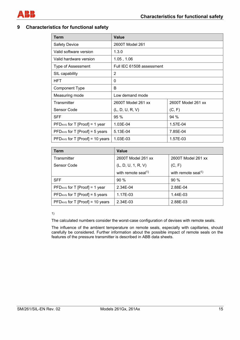
9 Characteristics for functional safety Pos: 26 /SIL Handbücher/Druck/261Gx, 261Ax/Merkmale der Funktionssicherheit @ 17\mod_1200898937703_3101.doc @ 153472
Term Value
Safety Device 2600T Model 261
Valid software version 1.3.0
Valid hardware version 1.05 , 1.06
Type of Assessment Full IEC 61508 assessment
SIL capability 2
HFT 0
Component Type B
Measuring mode Low demand mode
Transmitter
Sensor Code
2600T Model 261 xx
(L, D, U, R, V)
2600T Model 261 xx
(C, F)
SFF 95 % 94 %
PFDAVG for T [Proof] = 1 year 1.03E-04 1.57E-04
PFDAVG for T [Proof] = 5 years 5.13E-04 7.85E-04
PFDAVG for T [Proof] = 10 years 1.03E-03 1.57E-03 Term Value
Transmitter
Sensor Code
2600T Model 261 xx
(L, D, U, 1, R, V)
with remote seal1)
2600T Model 261 xx
(C, F)
with remote seal1)
SFF 90 % 90 %
PFDAVG for T [Proof] = 1 year 2.34E-04 2.88E-04
PFDAVG for T [Proof] = 5 years 1.17E-03 1.44E-03
PFDAVG for T [Proof] = 10 years 2.34E-03 2.88E-03 1)
The calculated numbers consider the worst-case configuration of devises with remote seals.
The influence of the ambient temperature on remote seals, especially with capillaries, should carefully be considered. Further information about the possible impact of remote seals on the features of the pressure transmitter is described in ABB data sheets.
Pos: 27 /======= Seitenumbruch ======== @ 0\mod_1126532365768_3101.doc @ 3830

Appendix
16 Models 261Gx, 261Ax SM/261/SIL-EN Rev. 02
Pos: 28 /Überschriften/1/A - C/Anhang @ 0\mod_1132904773022_3101.doc @ 3134
10 Appendix Pos: 29 /Anhang/Allgemein/Rücksendeformular @ 0\mod_1132757486454_3101.doc @ 3820
Statement about the contamination of devices and components
The repair and/or maintenance of devices and components will only be performed when a completely filled out explanation is present.
Otherwise, the shipment can be rejected. This explanation may only be filled out and signed by authorized specialist personnel of the operator.
Customer details:
Company:
Address:
Contact person: Telephone:
Fax: E-Mail:
Device details:
Type: Serial no.:
Reason for the return/description of the defect:
Was this device used for working with substances which pose a threat or health risk?
Yes No
If yes, which type of contamination (please place an X next to the applicable items)
biological corrosive/irritating combustible (highly/extremely combustible)
toxic explosive other harmful substances
radioactive
Which substances have had contact with the device?
1.
2.
3.
We hereby certify that the devices/parts shipped were cleaned and are free from any dangerous or poisonous materials.
City, Date Signature and company stamp
Pos: 30 /======= Seitenumbruch ======== @ 0\mod_1126532365768_3101.doc @ 3830

Management summary
SM/261/SIL-EN Rev. 02 Models 261Gx, 261Ax 17
Pos: 31 /Überschriften/1/M - O/Management Summary @ 1\mod_1146735824046_3101.doc @ 8443
11 Management summary Pos: 32 /SIL Handbücher/Druck/261Gx, 261Ax/Management Summary @ 1\mod_1146735979625_3101.doc @ 8455
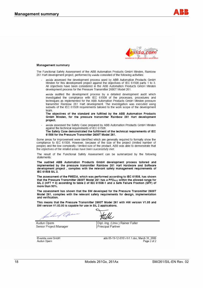
Management summary
18 Models 261Gx, 261Ax SM/261/SIL-EN Rev. 02
Pos: 33 /======= Seitenumbruch ======== @ 0\mod_1126532365768_3101.doc @ 3830

Declaration of conformity
SM/261/SIL-EN Rev. 02 Models 261Gx, 261Ax 19
Pos: 34 /Überschriften/1/J - L/Konformitätserklärung @ 1\mod_1146735880187_3101.doc @ 8450
12 Declaration of conformity Pos: 35 /SIL Handbücher/Druck/261Gx, 261Ax/Konformitätserklärung @ 17\mod_1200899125609_3101.doc @ 153496
M00386-1
Pos: 36 /Rückseiten/Minden_Druck @ 0\mod_1138784692484_3101.doc @ 3126 ===== Ende der Stückliste =====

ABB has Sales & Customer Support expertise in over 100 countries worldwide. www.abb.com/pressure
The Company’s policy is one of continuous productimprovement and the right is reserved to modify the
information contained herein without notice.
Printed in the Fed. Rep. of Germany (01.2008)
© ABB 2008
3KXP200002R4801
SM
/261
/SIL
-EN
Rev
. 02
ABB Limited Howard Road, St. Neots Cambridgeshire, PE19 8EU UK Tel: +44 (0)1480 475 321 Fax: +44 (0)1480 217 948
ABB Inc. 125 E. County Line Road Warminster, PA 18974 USA Tel: +1 215 674 6000 Fax: +1 215 674 7183
ABB Automation Products GmbH Schillerstr. 72 32425 Minden Germany Tel: +49 551 905-534 Fax: +49 551 905-555 [email protected]