sps differential pressure transmitter
TRANSCRIPT
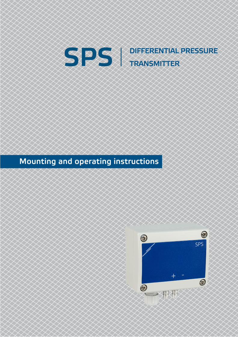
Mounting and operating instructions
SPS DIFFERENTIAL PRESSURE
TRANSMITTER
www.sentera.euMIW-SPS-EN-001 - 29 / 11 / 2018 2 - 12
Table of contents
SAFETY AND PRECAUTIONS 3
PRODUCT DESCRIPTION 4
ARTICLE CODES 4
INTENDED AREA OF USE 4
TECHNICAL DATA 4
STANDARDS 5
OPERATIONAL DIAGRAM 5
WIRING AND CONNECTIONS 5
MOUNTING INSTRUCTIONS IN STEPS 5
VERIFICATION OF INSTALLATION INSTRUCTIONS 8
OPERATING INSTRUCTIONS 8
MODBUS REGISTER MAPS 11
TRANSPORT AND STORAGE 12
WARRANTY AND RESTRICTIONS 12
MAINTENANCE 12
SPS DIFFERENTIAL PRESSURE TRANSMITTER
www.sentera.euMIW-SPS-EN-001 - 29 / 11 / 2018 3 - 12
back to the table of contents
SAFETY AND PRECAUTIONS
Read all the information, the datasheet, mounting and operating instructions and study the wiring and connection diagram before working with the product. For personal and equipment safety, and for optimum product performance, make sure you entirely understand the contents before installing, using, or maintaining this product.
For safety and licensing (CE) reasons, unauthorised conversion and / or modifications of the product are inadmissible.
The product should not be exposed to abnormal conditions, such as: extreme temperatures, direct sunlight or vibrations. Long-term exposure to chemical vapours in high concentration can affect the product performance. Make sure the work environment is as dry as possible; avoid condensation.
All installations shall comply with local health and safety regulations and local electrical standards and approved codes. This product can only be installed by an engineer or a technician who has expert knowledge of the product and safety precautions.
Avoid contacts with energised electrical parts; always treat the product as if it is live. Always disconnect the power supply before connecting, servicing or repairing the product.
Always verify that you apply appropriate power supply to the product and use appropriate wire size and characteristics. Make sure that all the screws and nuts are well tightened and fuses (if any) are fitted well.
Recycling of equipment and packaging should be taken into consideration and these should be disposed of in accordance with local and national legislation / regulations.
In case there are any questions that are not answered, please contact your technical support or consult a professional.
SPS DIFFERENTIAL PRESSURE TRANSMITTER
www.sentera.euMIW-SPS-EN-001 - 29 / 11 / 2018 4 - 12
back to the table of contents
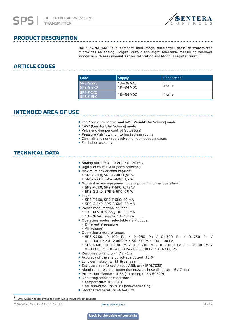
PRODUCT DESCRIPTION
The SPS-2K0/6K0 is a compact multi-range differential pressure transmitter. It provides an analog / digital output and eight selectable measuring windows alongside with easy manual sensor calibration and Modbus register reset.
ARTICLE CODES
Code Supply Connection
SPS-G-2K0SPS-G-6K0
13—26 VAC 18—34 VDC
3-wire
SPS-F-2K0SPS-F-6K0
18—34 VDC 4-wire
INTENDED AREA OF USE
■ Fan / pressure control and VAV (Variable Air Volume) mode ■ CAV* (Constant Air Volume) mode ■ Valve and damper control (actuators) ■ Pressure / airflow monitoring in clean rooms ■ Clean air and non-aggressive, non-combustible gases ■ For indoor use only
TECHNICAL DATA
■ Analog output: 0—10 VDC / 0—20 mA ■ Digital output: PWM (open collector) ■ Maximum power consumption:
► SPS-F-2K0, SPS-F-6K0: 0,96 W ► SPS-G-2K0, SPS-G-6K0: 1,2 W
■ Nominal or average power consumption in normal operation: ► SPS-F-2K0, SPS-F-6K0: 0,72 W ► SPS-G-2K0, SPS-G-6K0: 0,9 W
■ Imax: ► SPS-F-2K0, SPS-F-6K0: 40 mA ► SPS-G-2K0, SPS-G-6K0: 50 mA
■ Power consumption, no load: ► 18—34 VDC supply: 10—20 mA ► 13—26 VAC supply: 10—15 mA
■ Operating modes, selectable via Modbus: ► Differential pressure ► Air volume*
■ Operating pressure ranges: ► SPS-X-2K0: 0—100 Pa / 0—250 Pa / 0—500 Pa / 0—750 Pa / 0—1.000 Pa / 0—2.000 Pa / -50 - 50 Pa / -100—100 Pa
► SPS-X-6K0: 0—1.000 Pa / 0—1.500 Pa / 0—2.000 Pa / 0—2.500 Pa / 0—3.000 Pa / 0—4.000 Pa / 0—5.000 Pa / 0—6.000 Pa
■ Response time: 0,5 / 1 / 2 / 5 s ■ Accuracy of the analog voltage output: ±3 % ■ Long-term stability: ±1 % per year ■ Enclosure: reinforced plastic ABS, grey (RAL7035) ■ Aluminium pressure connection nozzles: hose diameter = 6 / 7 mm ■ Protection standard: IP65 (according to EN 60529) ■ Operating ambient conditions:
► temperature: 10—60 °C ► rel. humidity: < 95 % rH (non-condensing)
■ Storage temperature: -40—60 °C
* Only when K-factor of the fan is known (consult the datasheets)
SPS DIFFERENTIAL PRESSURE TRANSMITTER
www.sentera.euMIW-SPS-EN-001 - 29 / 11 / 2018 5 - 12
back to the table of contents
STANDARDS
■ Low Voltage Directive 2014/35/EC ■ EMC Directive 2014/30/EC ■ WEEE Directive 2012/19/EU ■ RoHs Directive 2011/65/EU
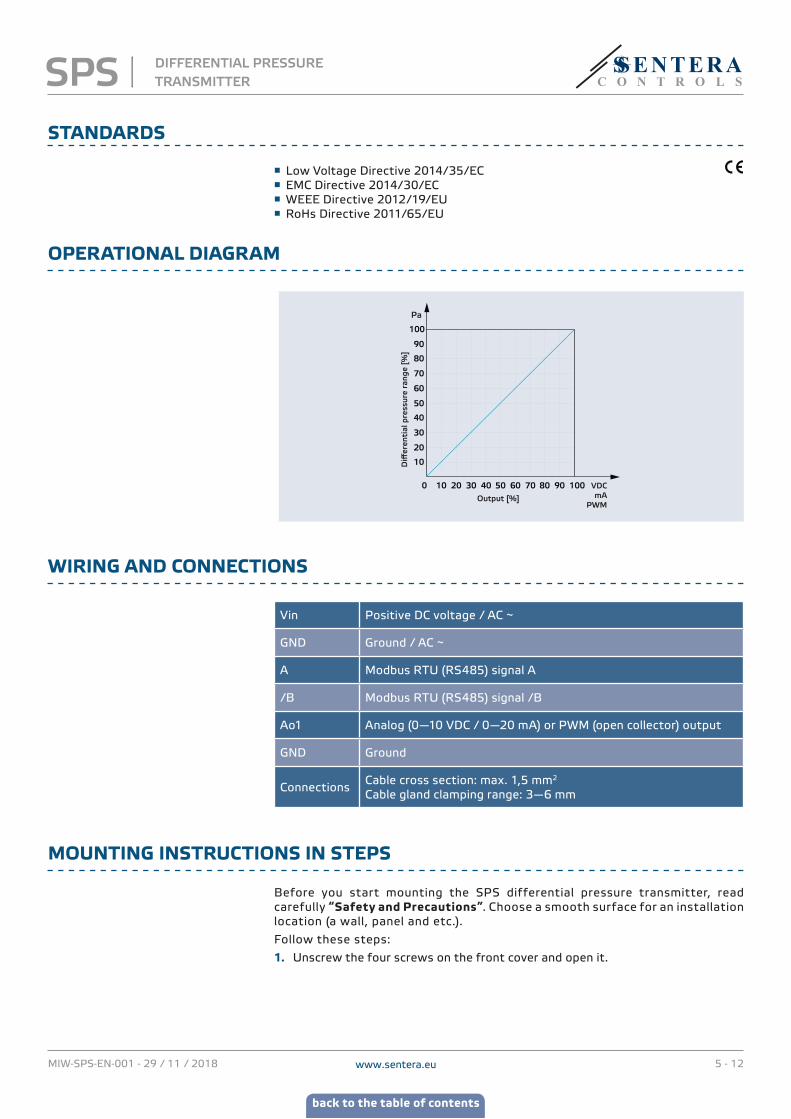
OPERATIONAL DIAGRAM
0 10 20 30 40 50 60 70 80 90 100
10
20
30
40
50
60
70
80
90
100
Diff
eren
tial
pre
ssur
e ra
nge
[%]
Output [%]
VDCmA
PWM
Pa
WIRING AND CONNECTIONS
Vin Positive DC voltage / AC ~
GND Ground / AC ~
A Modbus RTU (RS485) signal A
/B Modbus RTU (RS485) signal /B
Ao1 Analog (0—10 VDC / 0—20 mA) or PWM (open collector) output
GND Ground
ConnectionsCable cross section: max. 1,5 mm2
Cable gland clamping range: 3—6 mm
MOUNTING INSTRUCTIONS IN STEPS
Before you start mounting the SPS differential pressure transmitter, read carefully “Safety and Precautions”. Choose a smooth surface for an installation location (a wall, panel and etc.).
Follow these steps:
1. Unscrew the four screws on the front cover and open it.
SPS DIFFERENTIAL PRESSURE TRANSMITTER
www.sentera.euMIW-SPS-EN-001 - 29 / 11 / 2018 6 - 12
back to the table of contents
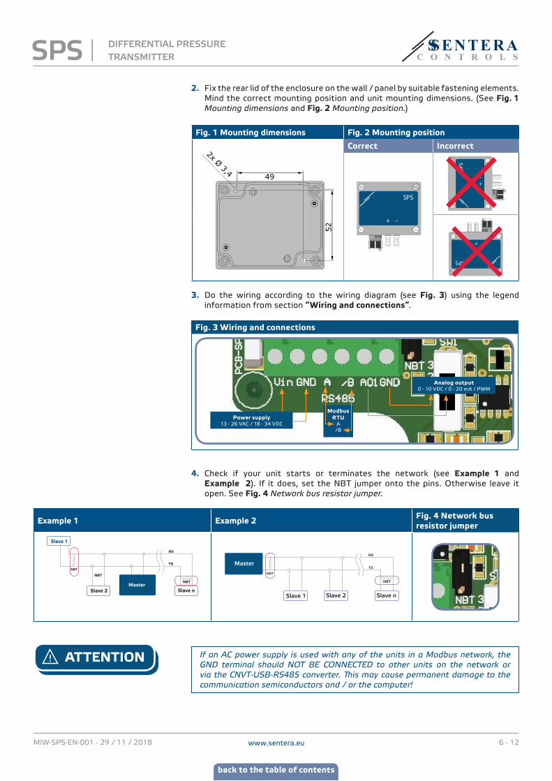
2. Fix the rear lid of the enclosure on the wall / panel by suitable fastening elements. Mind the correct mounting position and unit mounting dimensions. (See Fig. 1 Mounting dimensions and Fig. 2 Mounting position.)
Fig. 1 Mounting dimensions Fig. 2 Mounting position
2x Ø 3,449
52
Correct Incorrect
SPS
+ _
SPS
+_
SPS
+_
3. Do the wiring according to the wiring diagram (see Fig. 3) using the legend information from section “Wiring and connections”.
Fig. 3 Wiring and connections
Power supply13 - 26 VAC / 18 - 34 VDC
Analog output0 - 10 VDC / 0 - 20 mA / PWM
Modbus RTU
A/B
4. Check if your unit starts or terminates the network (see Example 1 and Example 2). If it does, set the NBT jumper onto the pins. Otherwise leave it open. See Fig. 4 Network bus resistor jumper.
Example 1 Example 2 Fig. 4 Network bus resistor jumper
RX
ТX
NBT
NBT
NBT
Slave 2Master
Slave n
Slave 1
Slave 2Slave 1
RX
ТX
NBT
NBT
Master
Slave n
ATTENTION If an AC power supply is used with any of the units in a Modbus network, the GND terminal should NOT BE CONNECTED to other units on the network or via the CNVT‑USB‑RS485 converter. This may cause permanent damage to the communication semiconductors and / or the computer!
SPS DIFFERENTIAL PRESSURE TRANSMITTER
www.sentera.euMIW-SPS-EN-001 - 29 / 11 / 2018 7 - 12
back to the table of contents
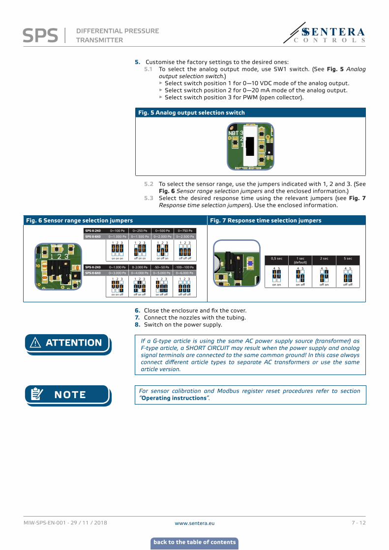
5. Customise the factory settings to the desired ones: 5.1 To select the analog output mode, use SW1 switch. (See Fig. 5 Analog
output selection switch.) ► Select switch position 1 for 0—10 VDC mode of the analog output. ► Select switch position 2 for 0—20 mA mode of the analog output. ► Select switch position 3 for PWM (open collector).
Fig. 5 Analog output selection switch
5.2 То select the sensor range, use the jumpers indicated with 1, 2 and 3. (See Fig. 6 Sensor range selection jumpers and the enclosed information.)
5.3 Select the desired response time using the relevant jumpers (see Fig. 7 Response time selection jumpers). Use the enclosed information.
Fig. 6 Sensor range selection jumpers Fig. 7 Response time selection jumpers
SPS-X-2K0 0—100 Pa 0—250 Pa 0—500 Pa 0—750 Pa
SPS-X-6K0 0—1.000 Pa 0—1.500 Pa 0—2.000 Pa 0—2.500 Pa
1 2 3
on on on
1 2 3
off on on
1 2 3
on off on
1 2 3
off off off
SPS-X-2K0 0—1.000 Pa 0- 2.000 Pa -50—50 Pa -100—100 Pa
SPS-X-6K0 0—3.000 Pa 0—4.000 Pa 0—5.000 Pa 0—6.000 Pa
1 2 3
on on off
1 2 3
off on off
1 2 3
on off off
1 2 3
off off off
0,5 sec 1 sec (default)
2 sec 5 sec
4 5
on on
4 5
on off
4 5
off on
4 5
off off
6. Close the enclosure and fix the cover. 7. Connect the nozzles with the tubing.8. Switch on the power supply.
ATTENTION If a G‑type article is using the same AC power supply source (transformer) as F‑type article, a SHORT CIRCUIT may result when the power supply and analog signal terminals are connected to the same common ground! In this case always connect different article types to separate AC transformers or use the same article version.
NOTE For sensor calibration and Modbus register reset procedures refer to section “Operating instructions”.
SPS DIFFERENTIAL PRESSURE TRANSMITTER
www.sentera.euMIW-SPS-EN-001 - 29 / 11 / 2018 8 - 12
back to the table of contents
VERIFICATION OF INSTALLATION INSTRUCTIONS
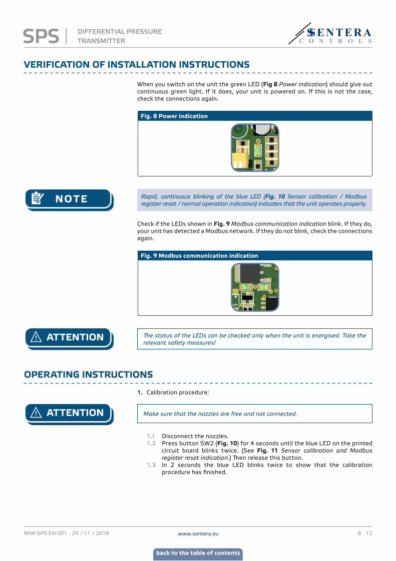
When you switch on the unit the green LED (Fig 8 Power indication) should give out continuous green light. If it does, your unit is powered on. If this is not the case, check the connections again.
Fig. 8 Power indication
NOTE Rapid, continuous blinking of the blue LED (Fig. 10 Sensor calibration / Modbus register reset / normal operation indication) indicates that the unit operates properly.
Check if the LEDs shown in Fig. 9 Modbus communication indication blink. If they do, your unit has detected a Modbus network. If they do not blink, check the connections again.
Fig. 9 Modbus communication indication
ATTENTION The status of the LEDs can be checked only when the unit is energised. Take the relevant safety measures!
OPERATING INSTRUCTIONS
1. Calibration procedure:
ATTENTION Make sure that the nozzles are free and not connected.
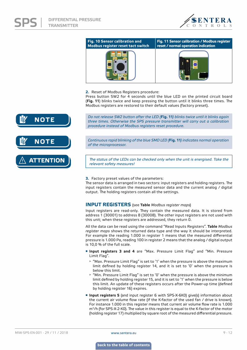
1.1 Disconnect the nozzles.1.2 Press button SW2 (Fig. 10) for 4 seconds until the blue LED on the printed
circuit board blinks twice. (See Fig. 11 Sensor calibration and Modbus register reset indication.) Then release this button.
1.3 In 2 seconds the blue LED blinks twice to show that the calibration procedure has finished.
SPS DIFFERENTIAL PRESSURE TRANSMITTER
www.sentera.euMIW-SPS-EN-001 - 29 / 11 / 2018 9 - 12
back to the table of contents
Fig. 10 Sensor calibration and Modbus register reset tact switch
Fig. 11 Sensor calibration / Modbus register reset / normal operation indication
2. Reset of Modbus Registers procedure:Press button SW2 for 4 seconds until the blue LED on the printed circuit board (Fig. 11) blinks twice and keep pressing the button until it blinks three times. The Modbus registers are restored to their default values (factory preset).
NOTE Do not release SW2 button after the LED (Fig. 11) blinks twice until it blinks again three times. Otherwise the SPS pressure transmitter will carry out a calibration procedure instead of Modbus registers reset procedure.
NOTE Continuous rapid blinking of the blue SMD LED (Fig. 11) indicates normal operation of the microprocessor.
ATTENTION The status of the LEDs can be checked only when the unit is energised. Take the relevant safety measures!
3. Factory preset values of the parameters:The sensor data is arranged in two sectors: input registers and holding registers. The input registers contain the measured sensor data and the current analog / digital output. The holding registers contain all the settings.
INPUT REGISTERS (see Table Modbus register maps)
Input registers are read-only. They contain the measured data. It is stored from address 1 (30001) to address 8 (30008). The other input registers are not used with this unit; when these registers are addressed, they return 0.
All the data can be read using the command “Read Inputs Registers”. Table Modbus register maps shows the returned data type and the way it should be interpreted. For example the reading 1.000 in register 1 means that the measured differential pressure is 1.000 Pa, reading 100 in register 2 means that the analog / digital output is 10,0 % of the full scale.
■ Input registers 3 and 4 are “Max. Pressure Limit Flag” and “Min. Pressure Limit Flag”.
► “Max. Pressure Limit Flag” is set to '1' when the pressure is above the maximum limit defined by holding register 14, and it is set to '0' when the pressure is below this limit.
► “Min. Pressure Limit Flag” is set to '0' when the pressure is above the minimum limit defined by holding register 15, and it is set to '1' when the pressure is below this limit. An update of these registers occurs after the Power-up time (defined by holding register 16) expires.
■ Input registers 5 (and input register 6 with SPS-X-6K0) give(s) information about the current air volume flow rate (if the K-factor of the used fan / drive is known). For instance 1.000 in this register means that current air volume flow rate is 1.000 m3/h (for SPS-X-2-K0). The value in this register is equal to the K-factor of the motor (holding register 17) multiplied by square root of the measured differential pressure.
SPS DIFFERENTIAL PRESSURE TRANSMITTER
www.sentera.euMIW-SPS-EN-001 - 29 / 11 / 2018 10 - 12
back to the table of contents
NOTE To get correct calculation of the volume flow rate, the correct K‑factor of the fan / drive has to be written in holding register 17!
■ Input register 7 gives information about the current working range. In Standalone mode it contains the working range which is set by jumpers 1, 2 and 3. In Modbus mode it contains the working range set via Modbus RTU (RS485) (mirror of holding register 12).
■ Input register 8 gives information about the current response time. In Standalone mode it contains the current response time set by jumpers 4 and 5. In Modbus mode it contains the current response time set via Modbus RTU (RS485) (mirror of holding register 13).
HOLDING REGISTERS (see Table Modbus register maps)
These registers are read / write registers and they can be managed with “Read Holding Registers” command, “Write single register” and “Write Multiple Registers” commands. They are separated in parts containing different kind of information.
Part 1:This part contains information about the unit and Modbus communication settings.
■ Register 1 (40001) contains the address at which the unit replies to the master unit in a Modbus network. The default address is '1'. It can be changed in two ways:
1. Send command “Write Single Register” with address '1' and write the new address value.
2. Connect only your unit to a master controller or use the 3SModbus PC application and send the command “Write Single Register” to address '0' (Modbus broadcast address), and write a new address value.
■ The next two registers (2 & 3) contain also Modbus settings. Changes in these registers change the communication settings. The default Modbus settings are 19200-E-1 as it is stated in the Modbus Protocol Specification.
■ The next three registers (4, 5 & 6) are read only. They keep information about the hardware and firmware versions.
■ The next four registers (7, 8, 9 and 10) are not used. They are read only.
NOTE Writing on these registers does not return Modbus error exception, however it does not change anything either!
Part 2:
■ Holding register 11 (40011) sets the mode of the SPS differential pressure transmitter. By sending the command “Write Single Register” with address 11 and data '2', the unit is set in Modbus mode. In this mode the range and response time settings are controlled via Modbus only; in Standalone mode these settings are controlled by the board jumpers. To change to Standalone mode it is necessary to send the command “Write Single Register” to address 11 with data '1'. Once the user has set the SPS unit in Modbus mode, it automatically sets the default range 0—1.000 Pa (value 4 in holding register 12) and the response time to 1 s (value 1 in holding register 13).
■ Holding register 12 (40012) sets the current range in Modbus mode. The default value is 4 (0—1.000 Pa range).
■ Holding register 13 (40013) sets the current response time in Modbus mode. The default value is 1 s.
■ Holding register 14 (40014) defines the maximum pressure limit. The default value is the maximum of the set range. When the measured pressure is higher or equal to this value, input register 3 (“Max Pressure Limit Flag”) sets to '1', otherwise it is '0'. This register accepts values between -100 and 2.000. When a value out of this range is written, the register returns to its default value. The maximum limit also depends on the current range. If the maximum limit in holding register 14 is higher than the maximum of the current range, it automatically becomes equal to the maximum of the range.
SPS DIFFERENTIAL PRESSURE TRANSMITTER
www.sentera.euMIW-SPS-EN-001 - 29 / 11 / 2018 11 - 12
back to the table of contents
■ Holding register 15 (40015) defines the minimum pressure limit. The default value is the minimum of the set range. When the measured pressure is below this value, input register 4 (“Min Pressure Limit Flag”) sets to '0', otherwise it is '1'. This register accepts values between -100 and 2.000. When a written value is out of this range, the register returns to its default value. The minimum value cannot be higher than the maximum value. Therefore, when a value higher than the maximum value is written in this register, it automatically becomes equal to the maximum value of the range.
■ Holding register 16 (40016) defines the “Power-Up Timer” value. The default value is 60 s. During this time the minimum pressure limit is not compared with the measured pressure values and “Min Pressure Limit Flag” register remains '0' for this period. You can change this register value only in the first 60 s after you switch on the unit.
■ Holding register 17 (40017) is the “K-factor” register. You should enter the correct K-factor of the used motor in it. The default value is '0' and the measured unit is differential pressure, not air volume / flow rate
■ The registers 18—20 are not used. They are read only.
NOTE Writing on these registers does not return Modbus error exception; however, it does not change anything either!
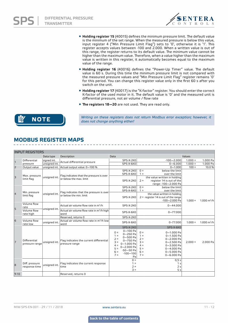
MODBUS REGISTER MAPS
INPUT REGISTERSData type Description Data Values
1Differential pressure
signed int.Actual differential pressure
SPS-X-2K0 -100—2.000 1.000 = 1.000 Paunsigned int. SPS-X-6K0 0—6.000 1.000 = 1.000 Pa
2 Output value unsigned int. Actual output value: 0—100 % 0—1.000 100 = 10.0 %
3Max. pressure limit flag
unsigned int.Flag indicates that the pressure is over or below the max. limit
SPS-X-2K0SPS-X-6K0
0 = 1 =
below the limitover the limit
SPS-X-2K0 2 = the value written in holding
register 14 is out of the range: -100—2.000 Pa
4Min. pressure limit flag
unsigned int.Flag indicates that the pressure is over or below the min. limit
SPS-X-2K0SPS-X-6K0
0 = 1 =
below the limitover the limit
1.000 = 1.000 m3/hSPS-X-2K0 2 =
the value written in holding register 14 is out of the range
-100—2.000 Pa
5
Volume flow rate
unsigned int.Actual air volume flow rate in m3/h SPS-X-2K0 0—44.000
Volume flow rate high
Actual air volume flow rate in m3/h high word
SPS-X-6K0 0—77.000
6Reserved, returns 0 SPS-X-2K0
Volume flow rate low
unsigned int.Actual air volume flow rate in m3/h low word
SPS-X-6K0 0–77.000 1.000 = 1.000 m3/h
7Differential pressure range
unsigned int.Flag indicates the current differential pressure range
SPS-X-2K0 SPS-X-6K0
2.000 = 2.000 Pa
0 =1 =2 =3 =4 =5 =6 =7 =
0—100 Pa 0—250 Pa0—500 Pa 0—750 Pa
0—1.000 Pa 0—2.000 Pa
-50—50 Pa-100—100
Pa
0 =1 =2 =3 =4 =5 =6 =7 =
0—1.000 Pa0—1.500 Pa0—2.000 Pa0—2.500 Pa0—3.000 Pa0—4.000 Pa0—5.000 Pa0—6.000 Pa
8Diff. pressure response time
unsigned int.Flag indicates the current response time
0 = 1 = 2 = 3 =
0,5 s1 s2 s5 s
9-10 Reserved, returns 0
SPS DIFFERENTIAL PRESSURE TRANSMITTER
www.sentera.euMIW-SPS-EN-001 - 29 / 11 / 2018 12 - 12
back to the table of contents
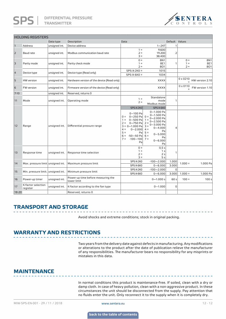
HOLDING REGISTERSData type Description Data Default Values
1 Address unsigned int. Device address 1—247 1
2 Baud rate unsigned int. Modbus communication baud rate1 =2 = 3 =
9.60019.200 38.400
2
3 Parity mode unsigned int. Parity check mode0 = 1 = 2 =
8N18E18O1
10 = 1 = 2 =
8N18E18O1
4 Device type unsigned int. Device type (Read only)SPS-X-2K0 = 1015
SPS-X-6K0 = 1034
5 HW version unsigned int. Hardware version of the device (Read only) XXXX0 x 0210
= HW version 2.10
6 FW version unsigned int. Firmware version of the device (Read only) XXXX0 x 0110
= FW version 1.10
7-10 unsigned int. Reserved, returns 0
11 Mode unsigned int. Operating mode1 = 2 =
Standalone mode
Modbus mode1
12 Range unsigned int. Differential pressure range
SPS-X-2K0 SPS-X-6K0
0 = 1 =2 = 3 = 4 = 5 = 6 =7 =
0—100 Pa 0—250 Pa0—500 Pa 0—750 Pa
0—1.000 Pa 0—2.000
Pa -50—50 Pa-100—100
Pa
0 = 1 =2 =3 =4 =5 = 6 = 7 =
0—1.000 Pa0—1.500 Pa0—2.000 Pa0—2.500 Pa0—3.000 Pa
0—4.000 Pa
0—5.000 Pa
0—6.000 Pa
4
13 Response time unsigned int. Response time selection
0 = 1 = 2 = 3 =
0,5 s 1 s 2 s5 s
1
14 Max. pressure limit unsigned int. Maximum pressure limitSPS-X-2K0 -100—2.000 1.000
1.000 = 1.000 PaSPS-X-6K0 0—6.000 3.000
15 Min. pressure limit. unsigned int. Minimum pressure limitSPS-X-2K0 -100—2.000 0
SPS-X-6K0 0—6.000 3.000 1.000 = 1.000 Pa
16 Power-up timer unsigned int.Power-up time before measuring the lower limit
0—1.000 s 60 s 100 = 100 s
17K-factor selection register
unsigned int. K-factor according to the fan type 0—1.000 0
18-20 Reserved, returns 0
TRANSPORT AND STORAGE
Avoid shocks and extreme conditions; stock in original packing.
WARRANTY AND RESTRICTIONS
Two years from the delivery date against defects in manufacturing. Any modifications or alterations to the product after the date of publication relieve the manufacturer of any responsibilities. The manufacturer bears no responsibility for any misprints or mistakes in this data.
MAINTENANCE
In normal conditions this product is maintenance-free. If soiled, clean with a dry or damp cloth. In case of heavy pollution, clean with a non-aggressive product. In these circumstances the unit should be disconnected from the supply. Pay attention that no fluids enter the unit. Only reconnect it to the supply when it is completely dry.
SPS DIFFERENTIAL PRESSURE TRANSMITTER