study of effect of advanced pvd coating on drilling of
TRANSCRIPT
Study of Effect of Advanced PVD coating on Drilling of
Nickel-based Superalloy Inconel 825
A thesis submitted in the fulfilment of the requirement for the degree of awards of
Master of Technology
In
Mechanical Engineering
(Production technology)
By
Shyam Sundar Luha
Roll No. 213ME2409
Under the supervision of
Dr. S. Gangopadhyay
Department of Mechanical Engineering
National Institute of Technology, Rourkela-769008
ODISHA, INDIA
2015
DEPARTMENT OF MECHANICAL ENGINEERING
National Institute Of Technology, Rourkela
Odisha, India- 769008
CERTIFICATE
This is to certify that the thesis entitled, “Study of Effect of Advanced PVD coating on
Drilling of Nickel-based Superalloy Inconel 825” submitted by Mr. Shyam Sundar Luha
bearing roll no. 213ME2409 in partial fulfillment of requirements for the award of Degree
of Master of Technology in Mechanical Engineering with specialization in “Production
Engineering” at National Institute of Technology, Rourkela is an authentic work carried out
by him under my guidance and supervision. To the best of my knowledge the matter embodied in
the thesis has not been submitted to any other University or Institute for the award of any Degree
or Diploma.
Date: 29-05-2015 Dr. S. Gangopadhyay
Assistant Professor
Department of Mechanical Engineering,
National Institute of Technology
Rourkela- 769008

Department of Mechanical Engineering
National Institute of Technology, Rourkela-769008
DECLARATION
I hereby declare that the report of work entitled “Study of Effect of Advanced PVD coating on
Drilling of Nickel-based Superalloy Inconel 825” is based on my own work carried out during
the course of my study under the supervision of Dr. S. Gangopadhyay.
I assert that the statements made and conclusions drawn are an outcome of the project work. I
further declare that to the best of my knowledge and belief that the report does not contain any
part of any work which has been already submitted for thesis evaluation in this university.
Name: Shyam Sundar Luha
Roll No: 213ME2409

Dedicated to My
Parents & Siblings
ACKNOWLEDGEMENT
Successful completion of work can never be one man’s task. It requires hard work in right
direction. There are many who have helped to make my experience as a student a
rewarding one.
In particular, I express my gratitude and deep regards to my guide Prof. S.
Gangopadhyay for his valuable guidance, constant encouragement and kind cooperation
throughout the period of work which has been instrumental in the success of thesis.
I also express my sincere gratitude to Prof. S.S. Mahapatra, Head of the Department,
Mechanical Engineering for his continuous support and insightful ideas. I am also
indebted to Prof. S.K. Sahoo, and Prof. M. Masanta for providing valuable departmental
facilities.
I am grateful to Prof. S.K. Patel for encouraging the use of correct grammar and consistent
notation in technical writings.
Last but not the least; I wish to express my sincere thanks to C.I.T.D. Hyderabad and
C.I.P.E.T. Bhubaneswar provided me with necessary facilities at various stages of this work.
Many friends have helped me stay sane through these difficult years. Their support and
care helped me overcome setbacks and stay focused on my research work. I greatly value their
friendship and I deeply appreciate their belief in me.
Shyam Sundar Luha
Roll No. 213ME2409
Department of Mechanical Engineering
National Institute of Technology
Rourkela- 769008
ABSTRACT
The drilling process of Inconel 825, a nickel-based superalloy, is very challenging due to the
material properties, the operating conditions and the high quality requirements. Moreover
because of its low thermal conductivity, heat is concentrated near the tool tip and unable to
dissipate causing tool wear. The current study investigates the influence of advanced PVD
coating on the tool in terms of its performance during drilling of nickel based superalloy Inconel
825. A cutting force model is developed and forces and torque is predicted for different
parameter settings. Systematic comparisons are made between the drilling performance of coated
and uncoated carbide tools by taking into account the surface roughness, thrust force and torque
utilizing analytical model, simulation and experiments. Force and torque are found to be less in
case of coated tool compared to uncoated counterpart. Surface finish was better at higher cutting
speed for PVD coated tool. Chip thickening is observed because of the constraints exerted on the
free flow of the chip in drilling. This chip resistance force is reduced using the coated tool as the
results show.
Keywords: Ni-based superalloy; PVD coatings; Drilling; Simulation
LIST OF FIGURES
Figure 1. Phase diagram of superalloy at different chemical composition and temperature [1] .... 2
Figure 2. Face centered cubic lattice of γ (left)and γ’(right) phase Nickel based Superalloy [1] .. 3
Figure 3. Co-ordinate systems with two different euler’s rotation ............................................... 25
Figure 4. Projection of element AA3 to derive 2nd euler’s angle ................................................ 33
Figure 5. (a) Cutting of parent stock using powr hacksaw (b) Facing of the Inconel in CNC
milling m/c .................................................................................................................................... 40
Figure 6. CNC vertical milling machine ....................................................................................... 41
Figure 7. (a) Experimental set up (b) Drilling operation performed on Inconel using carbide tool
....................................................................................................................................................... 41
Figure 8. (a) Sample of Inconel material after drilling is done (b) Multi-component digital force
indicator ........................................................................................................................................ 42
Figure 9. Analysis system (left) and static structural (right) used in the ANSYS simulation ...... 44
Figure 10. Material defined in the simulation ............................................................................... 45
Figure 11. Geometry of the drill bit as defined in the simulation ................................................. 45
Figure 12. Defining the loads applied to the drill bit .................................................................... 46
Figure 13. Solving the model and defining the output responces ................................................. 46
Figure 14. Thrust force and torque for uncoated tool using cutting force model ......................... 48
Figure 15. Thrust force and torque for coated tool using cutting force model ............................. 49
Figure 16. Thrust force and torque for Uncoated tool from experiment ...................................... 49
Figure 17. Thrust force and torque for Coated tool from experiment .......................................... 50
Figure 18. Variation of roughness with cutting speed for both uncoated (left) and coated tool
(right) ............................................................................................................................................ 51
Figure 19. Intermediate shapes obtained during drilling .............................................................. 54
Figure 20. Variation of chip thickness at different section of chip ............................................... 54
Figure 21. Variation of stress, strain and deformation for coated and uncoated drill bit with a
constant feed of 0.15 mm/rev ........................................................................................................ 56
Figure 22. Variation of stress, strain and deformation for coated and uncoated drill bit with a
constant cutting speed of 40 m/min .............................................................................................. 56
Figure 23. (a) Deformation (b) Strain and (c) Stress variation in Uncoated tool for trial no. 3 ... 56
Figure 24. Variation of stress in the tool....................................................................................... 57
LIST OF TABLES
Table 1. Properties and application of different gredes of Inconel ................................................. 6
Table 2. Elemental composition of Inconel 825 ............................................................................. 8
Table 3. Detail features of tool geometry ..................................................................................... 37
Table 4. Parametric setting for micro-blasting ............................................................................. 38
Table 5. Properties of TiAlN + AlCrN PVD multi-layered dual coating ..................................... 39
Table 6. The parameters set during the deposition technique in the cathodic arc deposition
chamber ......................................................................................................................................... 39
Table 7. Chemical composition of Inconel 825 ............................................................................ 40
Table 8. Physical and mechanical properties of Inconel 825 ........................................................ 40
Table 9. Predicted thrust force and torque estimated for coated and uncoated tool ..................... 48
Table 10. Thrust force and torque generated from experiment for coated and coated tool .......... 50
Table 11. Surface roughness measurements for the drilled holes ................................................. 51
Table 12. Chips at different section observed under optical microscope ..................................... 52
Table 13. Curl Radius at beginning of the drilling for coated and uncoated tool ......................... 55
Table 14. Simulation data generated by drilling of Inconel with carbide tools ............................ 55
Contents 1. INTRODUCTION .................................................................................................................................... 2
1.1 Application of Nickel based superalloy .............................................................................................. 4
1.2.1 Inconel 825 ................................................................................................................................... 8
1.3 Challenges encountered during machining of Ni-based superalloy .................................................... 8
1.4 Advanced Cutting Tool Materials ....................................................................................................... 9
1.4.1 Cemented Carbide ........................................................................................................................ 9
1.4.2 Ceramic ...................................................................................................................................... 10
1.4.4 Diamond ..................................................................................................................................... 11
1.4.5 Chemical Vapour Deposition (CVD) coated tools ..................................................................... 11
With advancement in the materials, their machining is proving to be a challenge even with the
existing tool materials. Coating has shown immense potential in further improvement of the
performance of the tool. CVD involves passing of a precursor gases into a chamber containing the
target to be coated. Target is heated before placing it in the chamber. Chemical reactions between the
target material and the gases occur on and near the vicinity of the surfaces, through which a thin film
is deposited on the surface. Unwanted products of the process are evaxuated along with the
unreacted source gases. ....................................................................................................................... 11
1.4.6 Physical Vapor Deposition (PVD) coated tool .......................................................................... 12
1.5 Significance of dry machining .......................................................................................................... 13
1.6 Simulation and modeling .................................................................................................................. 14
2. LITERATURE REVIEW ....................................................................................................................... 17
2.1 Effect of machining parameters on drilling of Ni-based superalloy ................................................. 17
2.2 Effect of environment on drilling of Ni-based superalloy ................................................................ 18
2.3 Effect on Surface Integrity during drilling of Ni-based superalloy .................................................. 18
2.4 Effect of performance of coating on tool during drilling of Ni-based superalloy ............................. 20
2.5 Modeling and simulation .................................................................................................................. 20
3. Objective ................................................................................................................................................. 23
4. CUTTING FORCE MODEL .................................................................................................................. 25
5. EXPERIMENTAL DETAILS ................................................................................................................ 37
5.1 Details of cutting tool substrate ........................................................................................................ 37
5.2 Macroscopic inspection .................................................................................................................... 37
5.3 Substrate Cleaning ............................................................................................................................ 37
5.4 Micro blasting as pre-treatment and post-treatment.......................................................................... 38
5.5 Details of Coating deposition ............................................................................................................ 38
5.6 Sample Description ........................................................................................................................... 39
5.7 Machining performance evaluation .................................................................................................. 40
6. SIMULATION ........................................................................................................................................ 44
6.1 Define the simulation Process ........................................................................................................... 44
6.2 Geometry and Material Definitions .................................................................................................. 44
6.3 Defining connections between bodies ............................................................................................... 45
6.4 Meshing of the bodies ....................................................................................................................... 45
6.5 Define loads and boundary conditions .............................................................................................. 46
6.6 Solving the model ............................................................................................................................. 46
6.7 Automated report generation ............................................................................................................ 46
7. RESULTS AND DISCUSSION ............................................................................................................. 48
7.1 Cutting force model .......................................................................................................................... 48
7.2 Experimental Results ........................................................................................................................ 49
7.3 Surface roughness ............................................................................................................................. 50
7.4 Chip Morphology .............................................................................................................................. 52
7.4.1 Chip Shape ................................................................................................................................. 52
7.4.2 Chip Thickening ......................................................................................................................... 54
7.5 Simulation ......................................................................................................................................... 55
8. CONCLUSION ....................................................................................................................................... 59
REFERENCES ........................................................................................................................................... 60

1 | P a g e
CHAPTER 1
INTRODUCTION
2 | P a g e
1. INTRODUCTION
Exhibiting properties like exceptional mechanical strength, good surface stability,
effective creep resistance and good corrosion and oxidation resistance, superalloys are high
performance alloys with the base element usually being cobalt, nickel, or nickel-iron. High
temperature strength observed in superalloy can be credited to solid solution strengthening. Heat
treatment process of age hardening is mindful precipitation of auxiliary phase such as gamma
prime and carbides. Generation of a protective oxide layer encapsulating the material provides
the oxidation and corrosion resistance necessary for protecting the rest of the component.
Aerospace industries are the main driving force for the development of superalloys. Nickel based
superalloys are particularly suited for their purpose. Titanium and Aluminum with a total
occupancy less than 10 atomic percent, are the key solutes in nickel based superalloys. As a
result, a two-phase equilibrium microstructure encompassing gamma-prime (γ') and gamma (γ)
is obtained. γ' can be hold accounted for the high temperature strength of the superalloy material
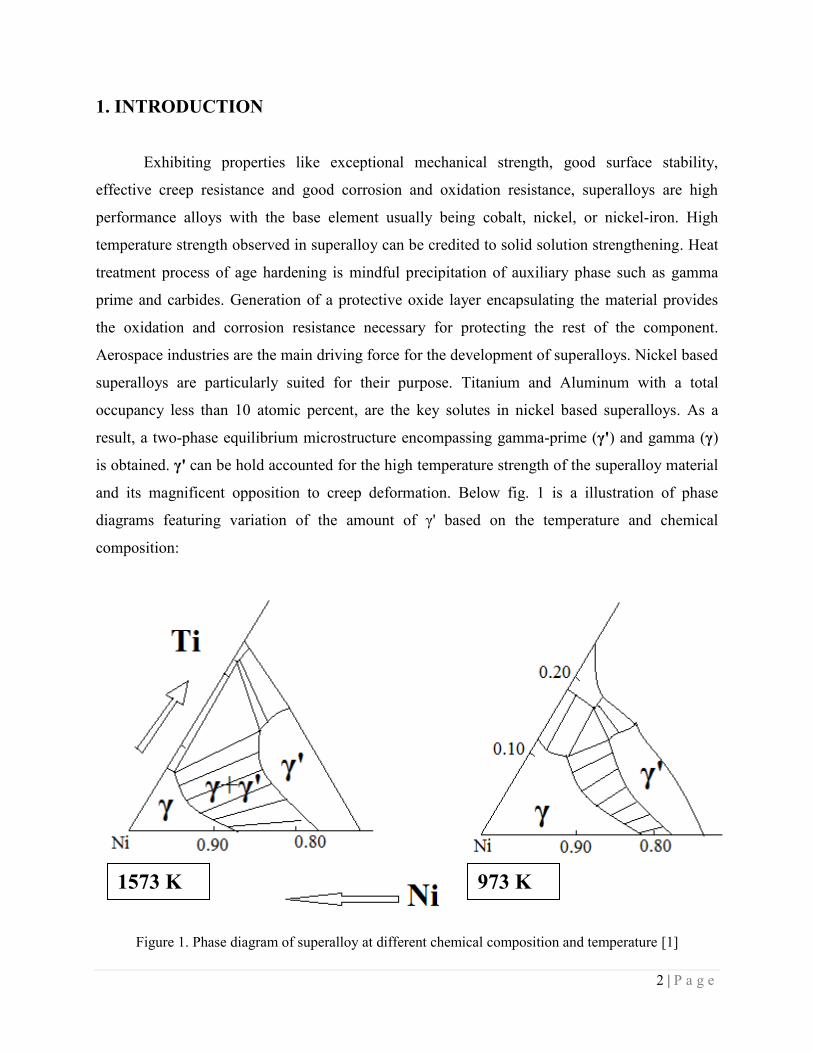
and its magnificent opposition to creep deformation. Below fig. 1 is a illustration of phase
diagrams featuring variation of the amount of γ' based on the temperature and chemical
composition:
Figure 1. Phase diagram of superalloy at different chemical composition and temperature [1]
1573 K 973 K
3 | P a g e
From the phase diagram it can be observed that for a particular chemical composition,
with increase in temperature γ' decreases. Hence, γ' is dissolved at a adequately high temperature
trailed by ageing at a lower temperature for a fine and uniform distribution of strengthening
precipitates. The gamma prime phase present in Ni-base superalloys behaves as an obstruction to
dislocation motion. It can also be regarded as a precipitate strengthener. Heat treatment of age
hardening when done carefully is able to control the gamma sizes with great accuracy. Usually as
the temperature increases most metal lose their strength, which can be explained by the thermal
excitation resulting in easier dislocation in the matrix. On contrary, nickel based super alloys
with the γ' particles are uniquely resistant to temperature. This stems from the fact that γ' is an
intermetallic compound.
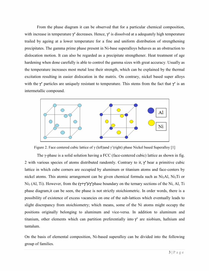
Figure 2. Face centered cubic lattice of γ (left)and γ’(right) phase Nickel based Superalloy [1]
The γ-phase is a solid solution having a FCC (face-centered cubic) lattice as shown in fig.
2 with various species of atoms distributed randomly. Contrary to it, γ' bear a primitive cubic
lattice in which cube corners are occupied by aluminum or titanium atoms and face-centers by
nickel atoms. This atomic arrangement can be given chemical formula such as Ni3Al, Ni3Ti or
Ni3 (Al, Ti). However, from the (γ+γ')/γ'phase boundary on the ternary sections of the Ni, Al, Ti
phase diagram,it can be seen, the phase is not strictly stoichiometric. In order words, there is a
possibility of existence of excess vacancies on one of the sub-lattices which eventually leads to
slight discrepancy from stoichiometry; which means, some of the Ni atoms might occupy the
positions originally belonging to aluminum and vice-versa. In addition to aluminum and
titanium, other elements which can partition preferentially into γ' are niobium, hafnium and
tantalum.
On the basis of elemental composition, Ni-based superalloy can be divided into the following
group of families.

4 | P a g e
1. Inconel - Utilized in the chemical processing industries in evaporator tubes, heaters, stills
and condensers and also a standard material used in the construction of nuclear reactors.
2. Nimonic - Gas turbine components, heat-treatment equipment and furnace parts.
3. Alloy 601 - Aluminum and silicon additions along with lower nickel content (61%)
improves nitriding and oxidation resistance chemical processing, aerospace, pollution
control, and power generation.
4. Waspaloy - Highly used for jet engine.
5. Alloy 718 - Niobium present in the alloy helps to overcome cracking problems during
welding. Applications found in cryogenic tankage and in land-based gas turbine and
aircraft engines.
6. Alloy X750 - Titanium and Aluminum additions help in the age hardening/strengthening
process. Used in gas turbines, nuclear reactors, rocket engines, tooling, pressure vessels,
and aircraft constitute.
7. Alloy X - Aerospace applications like High-temperature flat-rolled product.
8. ATI 718Plus - Being of lower cost and exceeding the operating temperature capability of
standard 718 alloy by 55 Cº (100 Fº), it is used by the engine manufacturers to improve
fuel efficiency.
9. Rene' N6 - 3rd
generation single crystal alloy used in jet engines.
10. TMS 162 - 5th
generation single crystal alloy for turbine blades
1.1 Application of Nickel based superalloy
Parts and segments produced using nickel based superalloy can withstand brutal and
harming environments, and exhibit properties like high thermal resistance, corrosion
resistance and acid resistance, they make perfect materials for usage in manufacturing of
pumps, valves, channeling frameworks, process equipments, turbines and congregations in
the marine, compound handling, oil and gas, aviation and military sectors. Nickel-base single
crystal super alloy have been utilized for a long time to produce temperature resistant turbine
blades. The 1st generation of single crystal superalloys did not contained any rhenium. In the late
1980s, 2nd
generation single crystal super alloys were created which were frequently utilized in
both commercial and military aircraft engines. These alloys typically contain 3% by weight of
rhenium, separating them from first generation single crystal superalloys into a different class.
5 | P a g e
Rene N5, CMSX-4, and PWA 1484 are some of the examples of second generation alloys.
Evolution of superalloy continued and 3rd
generation alloys were drafted to further enhance the
temperature capability and creep resistance. In these alloys, rhenium levels have been raised
above 5.5 % and a new material hafnium was introduced. Suitable examples of 3rd
generation
alloys include CMSX-10 and Rene N6. Superalloys are generally utilized in gas turbine
engines, particularly in those territories of the engine that are subject to elevated temperatures
and which demand excellent creep resistance, high strength, as well as good corrosion and
oxidation resistance. In turbine engines this region is seen in the high pressure turbine chamber.
Here blades face temperatures draw closer if not beyond their melting temperature. Modern jet
engines have proven to be efficient because of their higher operating temperatures, which
necessities higher-performing components to be assembled. The operating temperature can be
raised from 1200°F to 1300°F by using superalloys. In addition to increasing efficiency and
power output, higher operating temperature ensures complete combustion of fuel resulting in
reduced emissions of undesirable by-product. Apart from aerospace industries, nickel based
superalloys also play a significant role in boosting energy proficiency in steam turbines which
are being used to produce electricity. On an average, 480 grams of coal is consumed by the
world’s coal-fired power plants to produce 1 kilowatt-hour of electricity, which often results in
release 1,000 to 1,200 grams of CO2. Annually, almost eight billion tons of CO2 is released into
the environment by all coal-fired generation plants. Nonetheless, the newest plants with the help
of the most efficient systems have assimilated super alloys, and because of that can emit only
761 g of CO2 after burning as little amount as 320 g of coal per kilowatt-hour. Siemens is
developing new turbines which are focusing on the technology to produce only 669 g of CO2
for a expenditure of only 288 g of coal per kilowatt-hour. If all coal-fired power plants
utilize these technologies, without doubt such tremendous efficiency in fuel consumption would
result in tremendous reductions in annual global CO2 emissions. Oil and gas sector are another
field in which nickel-based super alloys are frequently finding applications in recent years. The
distinctive environments typically encountered in oil and natural gas production are often
corrosive and very challenging. Abundant levels of carbon dioxide, hydrogen sulfide, free sulfur,
and chlorides are regularly present. High pressure and temperatures up to 232°C (450˚ F) is often
encountered in some of these environments. Under these harsh and difficult environmental
conditions, processing of natural gas and oil requires materials of non-traditional nature. Nickel-
6 | P a g e
base superalloys 925, 725, and 718 are commonly used in natural gas and oil production.
Chrome and molybdenum present in these alloys aid in corrosion resistance. The main purpose
of developing Alloy 718 was to use it in gas turbines and aerospace industries, but recently it
has become one of the preferred material for the manufacture of sub-surface safety valves,
auxiliary and down-hole tools, and wellhead components.
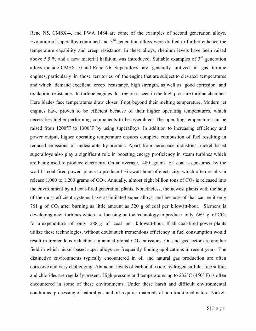
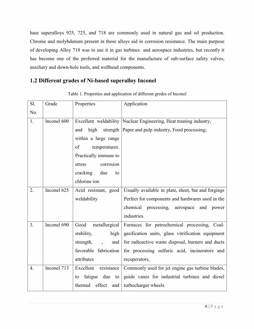
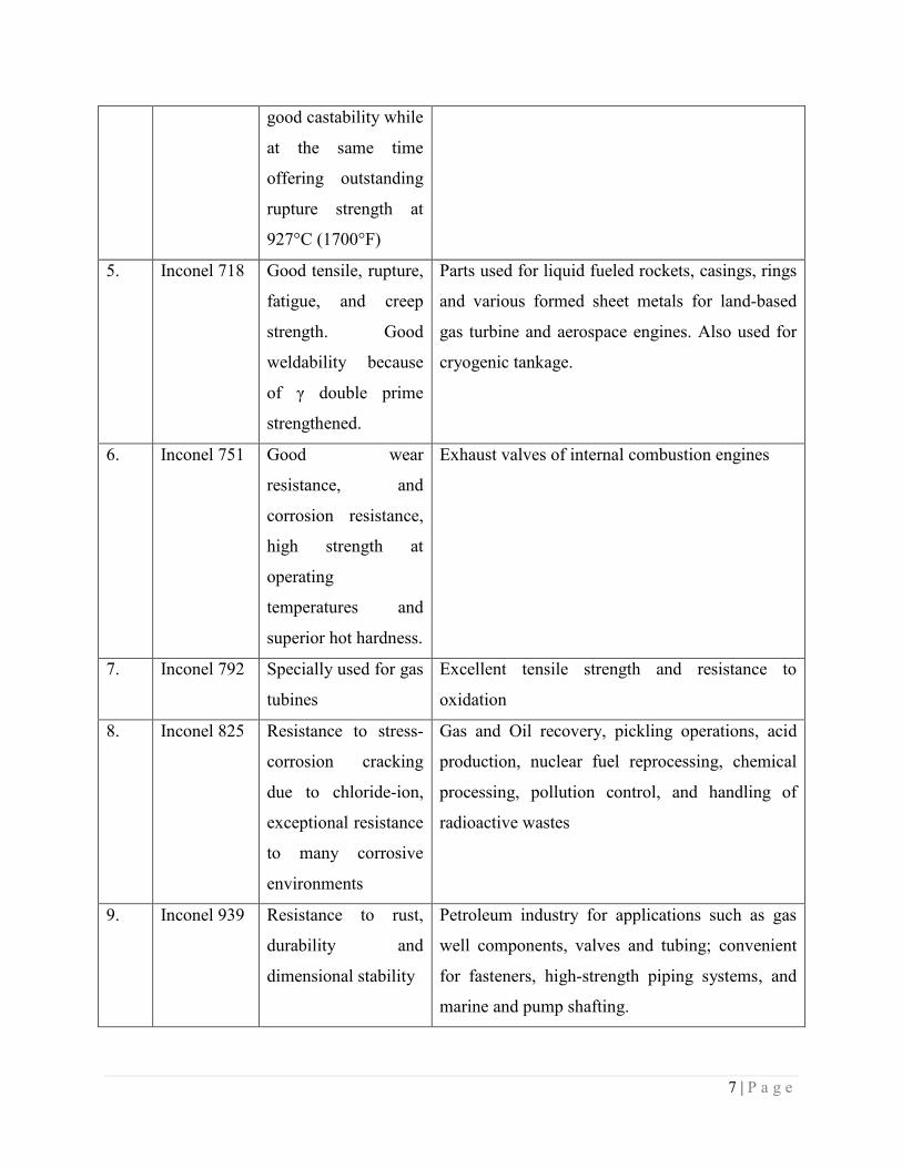
1.2 Different grades of Ni-based superalloy Inconel
Table 1. Properties and application of different gredes of Inconel
Sl.
No.
Grade Properties Application
1. Inconel 600 Excellent weldability
and high strength
within a large range
of temperatures.
Practically immune to
stress corrosion
cracking due to
chlorine ion
Nuclear Engineering, Heat treating industry,
Paper and pulp industry, Food processing;
2. Inconel 625 Acid resistant, good
weldability
Usually available in plate, sheet, bar and forgings
Perfect for components and hardwares used in the
chemical processing, aerospace and power
industries.
3. Inconel 690 Good metallurgical
stability, high
strength, , and
favorable fabrication
attributes
Furnaces for petrochemical processing, Coal-
gasification units, glass vitrification equipment
for radioactive waste disposal, burners and ducts
for processing sulfuric acid, incinerators and
recuperators,
4. Inconel 713 Excellent resistance
to fatigue due to
thermal effect and
Commonly used for jet engine gas turbine blades,
guide vanes for industrial turbines and diesel
turbocharger wheels
7 | P a g e
good castability while
at the same time
offering outstanding
rupture strength at
927°C (1700°F)
5. Inconel 718 Good tensile, rupture,
fatigue, and creep
strength. Good
weldability because
of γ double prime
strengthened.
Parts used for liquid fueled rockets, casings, rings
and various formed sheet metals for land-based
gas turbine and aerospace engines. Also used for
cryogenic tankage.
6. Inconel 751 Good wear
resistance, and
corrosion resistance,
high strength at
operating
temperatures and
superior hot hardness.
Exhaust valves of internal combustion engines
7. Inconel 792 Specially used for gas
tubines
Excellent tensile strength and resistance to
oxidation
8. Inconel 825 Resistance to stress-
corrosion cracking
due to chloride-ion,
exceptional resistance
to many corrosive
environments
Gas and Oil recovery, pickling operations, acid
production, nuclear fuel reprocessing, chemical
processing, pollution control, and handling of
radioactive wastes
9. Inconel 939 Resistance to rust,
durability and
dimensional stability
Petroleum industry for applications such as gas
well components, valves and tubing; convenient
for fasteners, high-strength piping systems, and
marine and pump shafting.
8 | P a g e
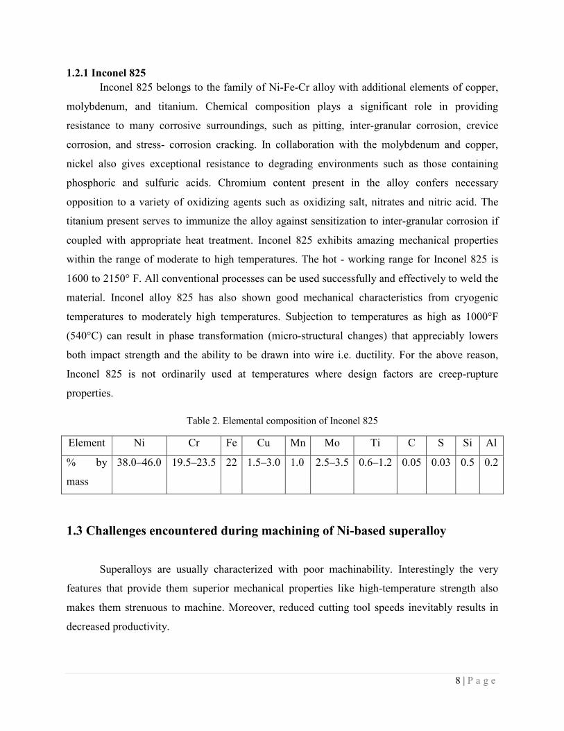
1.2.1 Inconel 825
Inconel 825 belongs to the family of Ni-Fe-Cr alloy with additional elements of copper,
molybdenum, and titanium. Chemical composition plays a significant role in providing
resistance to many corrosive surroundings, such as pitting, inter-granular corrosion, crevice
corrosion, and stress- corrosion cracking. In collaboration with the molybdenum and copper,
nickel also gives exceptional resistance to degrading environments such as those containing
phosphoric and sulfuric acids. Chromium content present in the alloy confers necessary
opposition to a variety of oxidizing agents such as oxidizing salt, nitrates and nitric acid. The
titanium present serves to immunize the alloy against sensitization to inter-granular corrosion if
coupled with appropriate heat treatment. Inconel 825 exhibits amazing mechanical properties
within the range of moderate to high temperatures. The hot - working range for Inconel 825 is
1600 to 2150° F. All conventional processes can be used successfully and effectively to weld the
material. Inconel alloy 825 has also shown good mechanical characteristics from cryogenic
temperatures to moderately high temperatures. Subjection to temperatures as high as 1000°F
(540°C) can result in phase transformation (micro-structural changes) that appreciably lowers
both impact strength and the ability to be drawn into wire i.e. ductility. For the above reason,
Inconel 825 is not ordinarily used at temperatures where design factors are creep-rupture
properties.
Table 2. Elemental composition of Inconel 825
Element Ni Cr Fe Cu Mn Mo Ti C S Si Al
% by
mass
38.0‒46.0 19.5‒23.5 22 1.5‒3.0 1.0 2.5‒3.5 0.6‒1.2 0.05 0.03 0.5 0.2
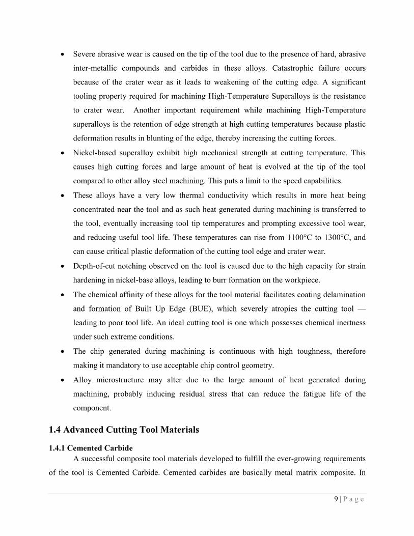
1.3 Challenges encountered during machining of Ni-based superalloy
Superalloys are usually characterized with poor machinability. Interestingly the very
features that provide them superior mechanical properties like high-temperature strength also
makes them strenuous to machine. Moreover, reduced cutting tool speeds inevitably results in
decreased productivity.
9 | P a g e
Severe abrasive wear is caused on the tip of the tool due to the presence of hard, abrasive
inter-metallic compounds and carbides in these alloys. Catastrophic failure occurs
because of the crater wear as it leads to weakening of the cutting edge. A significant
tooling property required for machining High-Temperature Superalloys is the resistance
to crater wear. Another important requirement while machining High-Temperature
superalloys is the retention of edge strength at high cutting temperatures because plastic
deformation results in blunting of the edge, thereby increasing the cutting forces.
Nickel-based superalloy exhibit high mechanical strength at cutting temperature. This
causes high cutting forces and large amount of heat is evolved at the tip of the tool
compared to other alloy steel machining. This puts a limit to the speed capabilities.
These alloys have a very low thermal conductivity which results in more heat being
concentrated near the tool and as such heat generated during machining is transferred to
the tool, eventually increasing tool tip temperatures and prompting excessive tool wear,
and reducing useful tool life. These temperatures can rise from 1100°C to 1300°C, and
can cause critical plastic deformation of the cutting tool edge and crater wear.
Depth-of-cut notching observed on the tool is caused due to the high capacity for strain
hardening in nickel-base alloys, leading to burr formation on the workpiece.
The chemical affinity of these alloys for the tool material facilitates coating delamination
and formation of Built Up Edge (BUE), which severely atropies the cutting tool —
leading to poor tool life. An ideal cutting tool is one which possesses chemical inertness
under such extreme conditions.
The chip generated during machining is continuous with high toughness, therefore
making it mandatory to use acceptable chip control geometry.
Alloy microstructure may alter due to the large amount of heat generated during
machining, probably inducing residual stress that can reduce the fatigue life of the
component.
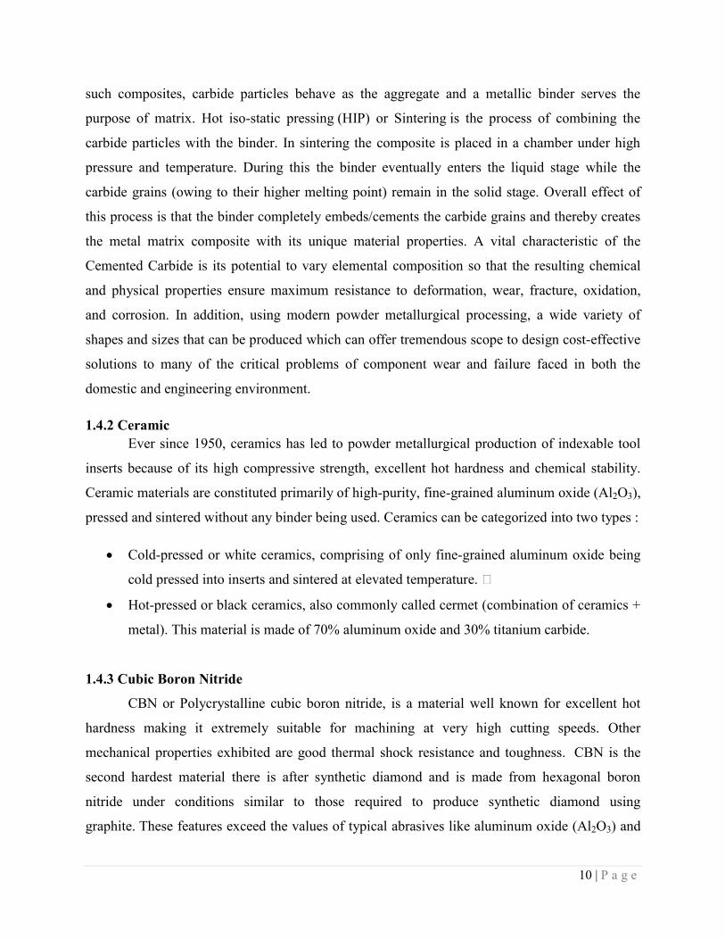
1.4 Advanced Cutting Tool Materials
1.4.1 Cemented Carbide
A successful composite tool materials developed to fulfill the ever-growing requirements
of the tool is Cemented Carbide. Cemented carbides are basically metal matrix composite. In
10 | P a g e
such composites, carbide particles behave as the aggregate and a metallic binder serves the
purpose of matrix. Hot iso-static pressing (HIP) or Sintering is the process of combining the
carbide particles with the binder. In sintering the composite is placed in a chamber under high
pressure and temperature. During this the binder eventually enters the liquid stage while the
carbide grains (owing to their higher melting point) remain in the solid stage. Overall effect of
this process is that the binder completely embeds/cements the carbide grains and thereby creates
the metal matrix composite with its unique material properties. A vital characteristic of the
Cemented Carbide is its potential to vary elemental composition so that the resulting chemical
and physical properties ensure maximum resistance to deformation, wear, fracture, oxidation,
and corrosion. In addition, using modern powder metallurgical processing, a wide variety of
shapes and sizes that can be produced which can offer tremendous scope to design cost-effective
solutions to many of the critical problems of component wear and failure faced in both the
domestic and engineering environment.
1.4.2 Ceramic
Ever since 1950, ceramics has led to powder metallurgical production of indexable tool
inserts because of its high compressive strength, excellent hot hardness and chemical stability.
Ceramic materials are constituted primarily of high-purity, fine-grained aluminum oxide (Al2O3),
pressed and sintered without any binder being used. Ceramics can be categorized into two types :
Cold-pressed or white ceramics, comprising of only fine-grained aluminum oxide being
cold pressed into inserts and sintered at elevated temperature. •
Hot-pressed or black ceramics, also commonly called cermet (combination of ceramics +
metal). This material is made of 70% aluminum oxide and 30% titanium carbide.
1.4.3 Cubic Boron Nitride
CBN or Polycrystalline cubic boron nitride, is a material well known for excellent hot
hardness making it extremely suitable for machining at very high cutting speeds. Other
mechanical properties exhibited are good thermal shock resistance and toughness. CBN is the
second hardest material there is after synthetic diamond and is made from hexagonal boron
nitride under conditions similar to those required to produce synthetic diamond using
graphite. These features exceed the values of typical abrasives like aluminum oxide (Al2O3) and
11 | P a g e
silicon carbide (SiC). Specifically, properties like high chemical resistance and thermal stability
make it desirable for machining ferrous materials, a scenario where synthetic diamond abrasives
are not generally used. Another physical advantage of using CBN compared to other
conventional abrasives is that, along with being harder at elevated temperature, it also maintains
this hardness over a wide range of temperature.
1.4.4 Diamond
The hardest material known to man on the earth is Diamond. It is much more harder than
silicon carbide and corundum. Diamond is exceptionally known for extremely high strength, low
friction coefficient, and good wear resistance. Other advantages availed by Diamond are low
grinding force, high grinding efficiency, long dressing period and long lifespan.
1.4.5 Chemical Vapour Deposition (CVD) coated tools
With advancement in the materials, their machining is proving to be a challenge even
with the existing tool materials. Coating has shown immense potential in further improvement of
the performance of the tool. CVD involves passing of a precursor gases into a chamber
containing the target to be coated. Target is heated before placing it in the chamber. Chemical
reactions between the target material and the gases occur on and near the vicinity of the surfaces,
through which a thin film is deposited on the surface. Unwanted products of the process are
evaxuated along with the unreacted source gases.
Different types of CVD coating can be summarized into the following categories:
Atmospheric Pressure Chemical Vapour Deposition
Chemical Beam Epitaxy
Chemical Vapour Infiltration
Laser Chemical Vapour Deposition
Low Pressure Chemical Vapour Deposition
Metal-Organic Chemical Vapour Deposition
Photochemical Vapour Deposition
Plasma Assisted or Enhanced Chemical Vapour Deposition
12 | P a g e
Advantages:
As they can deposited on any element or compound, they can be regarded as highly
versatile
Purity is high
Material is formed well under the melting point
CVD coatings deposited by are near net shape and conformal
As many components can be coated simultaneously, it is economical in production
1.4.6 Physical Vapor Deposition (PVD) coated tool
Typically used Physical Vapor Deposition coating processes are sputtering (using
magnetrons which are magnetic enhanced sources, cylindrical or hollow cathode sources) and
evaporation (generally involving electron beam sources or cathodic arc). All these processes
take place in vacuum with a working pressure (typically in range of 10-6
bar) and generally
requiring impingement of the substrate to be coated during the coating process with highly
energetic positively charged ions to promote high density. In addition, reactive gases such as
acetylene, nitrogen, or oxygen may also be introduced into the coating chamber during
deposition process to create various compound coating with varying compositions. The result of
this process is a very strong adhesive bond between the tooling substrate and the coating and
tailored structural, physical, and tribological film properties.
Various PVD coating processes are as follows
Sputter deposition
Pulsed laser deposition(PLD)
Evaporative deposition
Electron beam physical vapor deposition(EBPVD)
Cathodic Arc Deposition (CAD)
Advantages:
Coatings obtained from PVD are sometimes more corrosion resistant and harder
compared to coatings applied using electroplating process. Properties exhibited by these
13 | P a g e
coatings are excellent abrasion resistance, good impact and high temperature strength,
and are durable enough so as to not requiring any protective topcoats
These coating have the capability to use virtually some organic and any type of inorganic
coating materials on an equally diverse group of surfaces and substrates using a large
variety of finishes.
Compared to the traditional coating processes such as painting and electroplating, PVD
coatings are more eco-friendly.
A certain film can be deposited using any one of the PVD technique available.
1.5 Significance of dry machining
Some advantages of dry machining over wet machining are include below:
No pollution of the atmosphere (or water), hence environment friendly.
There is no residue present on the swarf which is reflected in reduced cleaning costs and
disposal
No serious danger to health. Dry machining is allergy free and non-injurious to skin.
Moreover, cost reduction is achieved in machining process.
Over the recent two decades, there has been dramatic change in the economics of
utilization of cutting fluids. During 1980s, buying, maintaining, and disposing of cutting fluids
accounted for only 3 % of the total cost of most machining jobs. Today, including their
management and disposal, cutting fluids account for around 16 % of the cost of the average job.
Cutting tools, on the other hand, account for only about 4 % of the total cost of a machining job.
For the chance to eliminate the headaches and cost of maintaining cutting fluids, this cost also
accepts a slightly shorter tool life as it is a less expensive choice. From pollution point of view,
cutting fluids have a larger environmental impact compared to the dry machining. MQL
generally uses aerosol which gets vaporized due to high temperature of cutting. These vapors
mix with the atmospheric air and are inhales by the worker. In long run, severe deterioration of
health is often observed among people who are exposed to it on a regular basis.
14 | P a g e
1.6 Simulation and modeling
The modeling of machining processes has spread widely across the world today, with
large no. of researchers developing models to predict metal-cutting performance in more
effective manner. The objective for this is to provide an authentic answer to the challenges faced
by the machining industry, which is presently placed under very tight environmental and
economical constraints. Process planning systems are integrating simulation with the predictive
models to enhance product quality and improve productivity. Predictive performance models
have also been used effectively in adaptive control for machining operations, reducing or/and
eradicating trial and error approaches. In recent years much new advancement has occurred in
different area like laser technology, aerospace industries, etc. Virtual manufacturing is being
used for the testing of these developments. Finite element method is being extensively used to
develop model to study thermal, mechanical and physical aspects of the machining process
which are otherwise difficult to investigate simultaneous. The various fields in which the
simulation has found its application are
Performance optimization
Video games
Testing and training
Education
Depending on the resources available and the type of analysis required, the following approaches
have been identified.
Analytical model: Slip-line theory or also called minimum energy principles are
employed for this approach. With its aid one can predicts cutting forces, chip geometry,
tool–chip contact length, average stresses, strains, strain-rates and temperatures.
Numerical model: Concepts used by these models are continuum mechanics using FEM,
FDM & mesh-less FEM. It also predicts forces, chip geometry, stresses, strain, strain-
rates and temperatures.
AI-based model

15 | P a g e
Emperical model: It utilizes curve fitting of experimental data. Applicable to most
machining operations for measurable process variables only. However, it is Valid only
for the range of experimentation.

16 | P a g e
CHAPTER 2
LITERATURE REVIEW
17 | P a g e
2. LITERATURE REVIEW
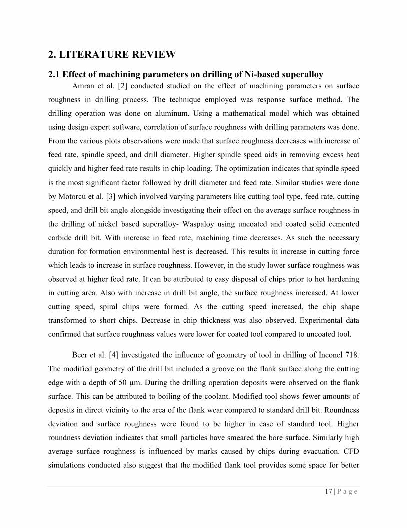
2.1 Effect of machining parameters on drilling of Ni-based superalloy
Amran et al. [2] conducted studied on the effect of machining parameters on surface
roughness in drilling process. The technique employed was response surface method. The
drilling operation was done on aluminum. Using a mathematical model which was obtained
using design expert software, correlation of surface roughness with drilling parameters was done.
From the various plots observations were made that surface roughness decreases with increase of
feed rate, spindle speed, and drill diameter. Higher spindle speed aids in removing excess heat
quickly and higher feed rate results in chip loading. The optimization indicates that spindle speed
is the most significant factor followed by drill diameter and feed rate. Similar studies were done
by Motorcu et al. [3] which involved varying parameters like cutting tool type, feed rate, cutting
speed, and drill bit angle alongside investigating their effect on the average surface roughness in
the drilling of nickel based superalloy- Waspaloy using uncoated and coated solid cemented
carbide drill bit. With increase in feed rate, machining time decreases. As such the necessary
duration for formation environmental hest is decreased. This results in increase in cutting force
which leads to increase in surface roughness. However, in the study lower surface roughness was
observed at higher feed rate. It can be attributed to easy disposal of chips prior to hot hardening
in cutting area. Also with increase in drill bit angle, the surface roughness increased. At lower
cutting speed, spiral chips were formed. As the cutting speed increased, the chip shape
transformed to short chips. Decrease in chip thickness was also observed. Experimental data
confirmed that surface roughness values were lower for coated tool compared to uncoated tool.
Beer et al. [4] investigated the influence of geometry of tool in drilling of Inconel 718.
The modified geometry of the drill bit included a groove on the flank surface along the cutting
edge with a depth of 50 µm. During the drilling operation deposits were observed on the flank
surface. This can be attributed to boiling of the coolant. Modified tool shows fewer amounts of
deposits in direct vicinity to the area of the flank wear compared to standard drill bit. Roundness
deviation and surface roughness were found to be higher in case of standard tool. Higher
roundness deviation indicates that small particles have smeared the bore surface. Similarly high
average surface roughness is influenced by marks caused by chips during evacuation. CFD
simulations conducted also suggest that the modified flank tool provides some space for better
18 | P a g e
flow recirculation of coolant. Kwong et al. [6] investigated the influence of process parameters
like cutting edge quality, feed rate, cutting speed, and cooling environment on drilling of nickel
based superalloy RR1000. They quantified the sub-surface damage alongside hoop and axial
distribution of residual stress. The micro hardness of drilled surface increased significantly at
higher cutting speeds which is a result of higher temperature and more intense heating-cooling
cycles. Compressive residual stresses were observed in the axial direction which declines to 0 at
a depth of 100 µm. The main contributor for this is the full feed force of drilling.
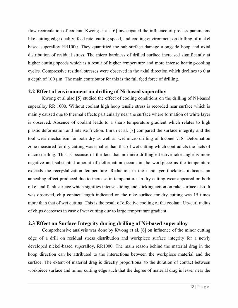
2.2 Effect of environment on drilling of Ni-based superalloy
Kwong et al also [5] studied the effect of cooling conditions on the drilling of NI-based
superalloy RR 1000. Without coolant high hoop tensile stress is recorded near surface which is
mainly caused due to thermal effects particularly near the surface where formation of white layer
is observed. Absence of coolant leads to a sharp temperature gradient which relates to high
plastic deformation and intense friction. Imran et al. [7] compared the surface integrity and the
tool wear mechanism for both dry as well as wet micro-drilling of Inconel 718. Deformation
zone measured for dry cutting was smaller than that of wet cutting which contradicts the facts of
macro-drilling. This is because of the fact that in micro-drilling effective rake angle is more
negative and substantial amount of deformation occurs in the workpiece as the temperature
exceeds the recrystalization temperature. Reduction in the nanolayer thickness indicates an
annealing effect produced due to increase in temperature. In dry cutting wear appeared on both
rake and flank surface which signifies intense sliding and sticking action on rake surface also. It
was observed, chip contact length indicated on the rake surface for dry cutting was 15 times
more than that of wet cutting. This is the result of effective cooling of the coolant. Up-curl radius
of chips decreases in case of wet cutting due to large temperature gradient.
2.3 Effect on Surface Integrity during drilling of Ni-based superalloy
Comprehensive analysis was done by Kwong et al. [6] on influence of the minor cutting
edge of a drill on residual stress distribution and workpiece surface integrity for a newly
developed nickel-based superalloy, RR1000. The main reason behind the material drag in the
hoop direction can be attributed to the interactions between the workpiece material and the
surface. The extent of material drag is directly proportional to the duration of contact between
workpiece surface and minor cutting edge such that the degree of material drag is lesser near the
19 | P a g e
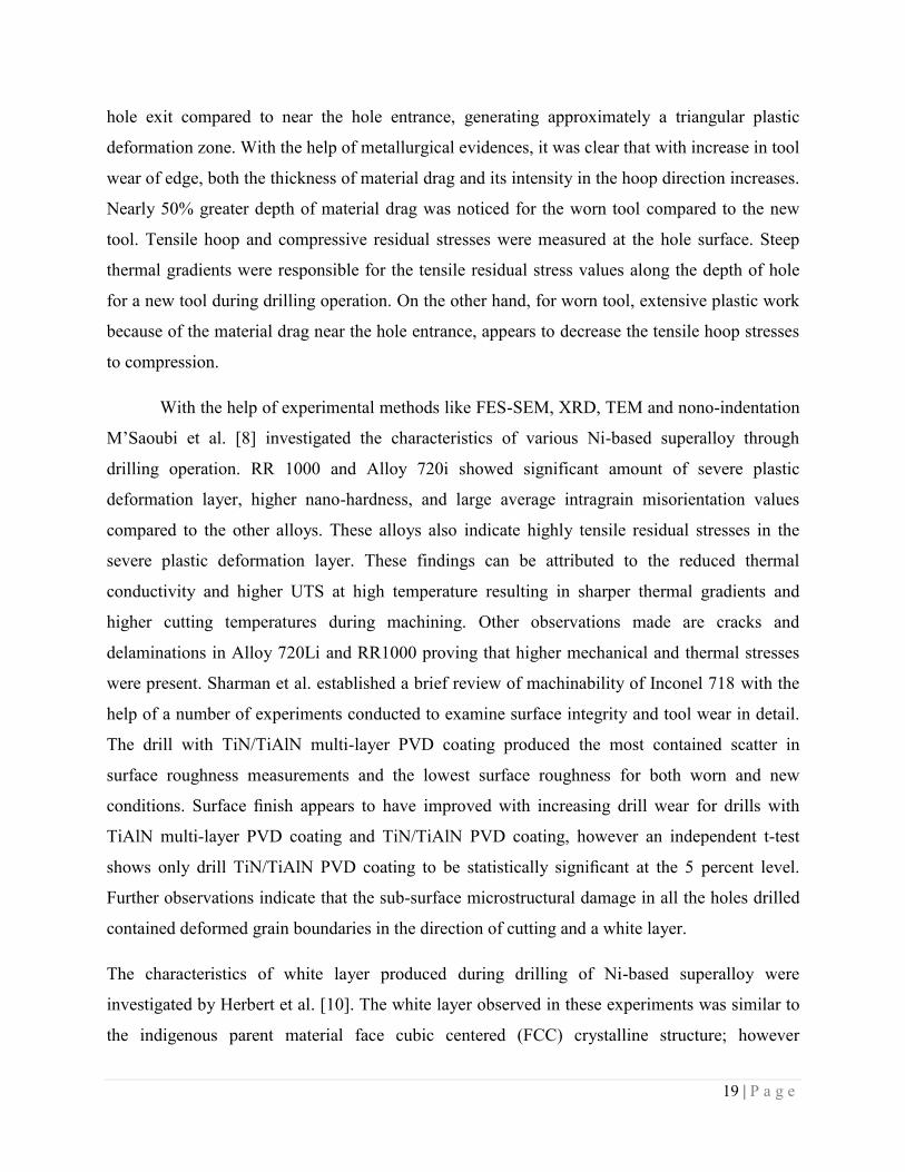
hole exit compared to near the hole entrance, generating approximately a triangular plastic
deformation zone. With the help of metallurgical evidences, it was clear that with increase in tool
wear of edge, both the thickness of material drag and its intensity in the hoop direction increases.
Nearly 50% greater depth of material drag was noticed for the worn tool compared to the new
tool. Tensile hoop and compressive residual stresses were measured at the hole surface. Steep
thermal gradients were responsible for the tensile residual stress values along the depth of hole
for a new tool during drilling operation. On the other hand, for worn tool, extensive plastic work
because of the material drag near the hole entrance, appears to decrease the tensile hoop stresses
to compression.
With the help of experimental methods like FES-SEM, XRD, TEM and nono-indentation
M’Saoubi et al. [8] investigated the characteristics of various Ni-based superalloy through
drilling operation. RR 1000 and Alloy 720i showed significant amount of severe plastic
deformation layer, higher nano-hardness, and large average intragrain misorientation values
compared to the other alloys. These alloys also indicate highly tensile residual stresses in the
severe plastic deformation layer. These findings can be attributed to the reduced thermal
conductivity and higher UTS at high temperature resulting in sharper thermal gradients and
higher cutting temperatures during machining. Other observations made are cracks and
delaminations in Alloy 720Li and RR1000 proving that higher mechanical and thermal stresses
were present. Sharman et al. established a brief review of machinability of Inconel 718 with the
help of a number of experiments conducted to examine surface integrity and tool wear in detail.
The drill with TiN/TiAlN multi-layer PVD coating produced the most contained scatter in
surface roughness measurements and the lowest surface roughness for both worn and new
conditions. Surface finish appears to have improved with increasing drill wear for drills with
TiAlN multi-layer PVD coating and TiN/TiAlN PVD coating, however an independent t-test
shows only drill TiN/TiAlN PVD coating to be statistically significant at the 5 percent level.
Further observations indicate that the sub-surface microstructural damage in all the holes drilled
contained deformed grain boundaries in the direction of cutting and a white layer.
The characteristics of white layer produced during drilling of Ni-based superalloy were
investigated by Herbert et al. [10]. The white layer observed in these experiments was similar to
the indigenous parent material face cubic centered (FCC) crystalline structure; however
20 | P a g e
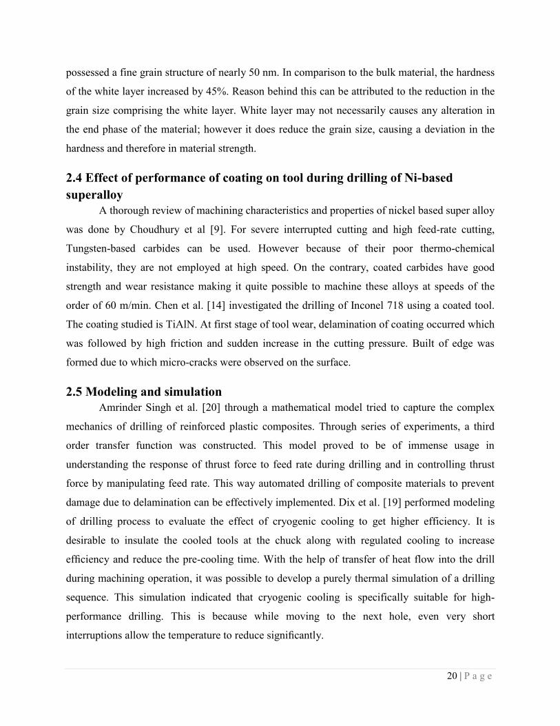
possessed a fine grain structure of nearly 50 nm. In comparison to the bulk material, the hardness
of the white layer increased by 45%. Reason behind this can be attributed to the reduction in the
grain size comprising the white layer. White layer may not necessarily causes any alteration in
the end phase of the material; however it does reduce the grain size, causing a deviation in the
hardness and therefore in material strength.
2.4 Effect of performance of coating on tool during drilling of Ni-based
superalloy
A thorough review of machining characteristics and properties of nickel based super alloy
was done by Choudhury et al [9]. For severe interrupted cutting and high feed-rate cutting,
Tungsten-based carbides can be used. However because of their poor thermo-chemical
instability, they are not employed at high speed. On the contrary, coated carbides have good
strength and wear resistance making it quite possible to machine these alloys at speeds of the
order of 60 m/min. Chen et al. [14] investigated the drilling of Inconel 718 using a coated tool.
The coating studied is TiAlN. At first stage of tool wear, delamination of coating occurred which
was followed by high friction and sudden increase in the cutting pressure. Built of edge was
formed due to which micro-cracks were observed on the surface.
2.5 Modeling and simulation
Amrinder Singh et al. [20] through a mathematical model tried to capture the complex
mechanics of drilling of reinforced plastic composites. Through series of experiments, a third
order transfer function was constructed. This model proved to be of immense usage in
understanding the response of thrust force to feed rate during drilling and in controlling thrust
force by manipulating feed rate. This way automated drilling of composite materials to prevent
damage due to delamination can be effectively implemented. Dix et al. [19] performed modeling
of drilling process to evaluate the effect of cryogenic cooling to get higher efficiency. It is
desirable to insulate the cooled tools at the chuck along with regulated cooling to increase
efficiency and reduce the pre-cooling time. With the help of transfer of heat flow into the drill
during machining operation, it was possible to develop a purely thermal simulation of a drilling
sequence. This simulation indicated that cryogenic cooling is specifically suitable for high-
performance drilling. This is because while moving to the next hole, even very short
interruptions allow the temperature to reduce significantly.
21 | P a g e
Zhang et al. [18] used finite element analysis to understand high speed ultra-sonic
assisted micro-drilling. Hybrid model presented by them provided sufficiently consistent results
with much better computation efficiency compared to the modest meshed solid model. Advanced
analyses of complicated geometry of drill are particularly benefited by this model. Finite element
simulation was done by Soo et al [11]. for ball end milling machining operation. Lagrangian
formulation was used for the model. It was observed that the forces generated from the model
were very close to the experimental data with an error margin of 6 %. Similarly for feed forces
the error margin was 29 %. Studying the chip morphology is difficult as hating the process at
certain time interval can be tedious and difficult. A useful sub routine using damage criteria was
introduced so that the chip segmentation can be easily simulated.
Similar studies were done on drilling operation by Schulze et al. [16] to develop a model
predicting the effect of cutting parameters on the hole generated by the process. Phase
transformation was also modeled by introducing the kinetics using user sub routine. Yana et
al.[17] generated a thermal model to simulate the drilling operation conducted on the Inconel 718
using a coated tool. The model accumulated data like heat flowing into the chip and the tool, thus
indicating the effectiveness of the coating.

22 | P a g e
CHAPTER 3
OBJECTIVE
23 | P a g e
3. Objective
Based on the literature review it was found that studies on drilling of Ni-based superalloy
have been done with particular emphasis on Inconel 718. Other important grades also required
similar research work. Comparative study of drilling of nickel-based superalloy with PVD-
coated and uncoated tool on basis of surface characteristics, modeling and chip morphology is
not done substantially. Only TiAlN-coated drill bits have been used for research without much
systematic comparison with its uncoated counterpart. Though coolants are very effective in
enhancing the performance of tool, huge capital has to be invested on them. This brings focus to
improve the performance of tool in dry environment. Advance tool material like CBN are
available, however such material are very expensive and not economically viable. Based on these
facts the following objectives were formulated.
1. To conduct a systematic comparison between drilling of nickel based superalloy Inconel
825 with coated and uncoated cemented carbide tool with the help of analytical model
proposed to determine the torque and thrust force during the operation.
2. To study the effect of cutting parameters on drilling operation of Inconel 825 with
cemented carbide tool on characteristics like force, torque and surface roughness.
3. To simulate the drilling process in ANSYS and generate necessary data like maximum
shear stress, strain and deformation.
4. To study chip morphology to get an insight of the effectiveness of coated tool in drilling
of Inconel 825.

24 | P a g e
CHAPTER 4
CUTTING FORCE MODEL
25 | P a g e
4. CUTTING FORCE MODEL
For estimation of the reactive forces acting on the desired element of the cutting edge,
most cutting force models usually use oblique based or orthogonal based cutting models. An
element can be defined as a small segment of the cutting edges, in this case of a drill, for which
oblique (or orthogonal cutting when the cutting condition facilitate) cutting can be assumed. This
means that different geometric parameters like inclination angle, cutting direction and other
angles used to define the slanting of both rake and relief faces are concluded to be constant
across the entire width of the segment. In order to obtain the forces acting in the thrust, torque
and lateral direction in the drilling process, the forces acting on the elements of the cutting edges
must be fragmented along these directions and then forces from all the elements present on the
cutting edge has to be added to acquire the total values of thrust force and torque and sometimes
lateral forces. The total thrust force and torque values are complete representatives to outline the
cutting forces involved in drilling. Usually lateral component of total force is zero for an ideal
drill with minimum of 2 flutes (because of the symmetry of flutes along the drill axis, the lateral
force components acting on a flute cancel each other) and therefore is not important unless
someone desires to study the effects of symmetry irregularities on the mechanical loads. Efficient
measurement of lateral force is possible only if the drill has only a single flute. This constitutes a
major problem in the calibration of cutting force models for drilling based using oblique cutting
as compared to other machining processes like turning, milling, etc. For the current work, a
mechanistic force model based on oblique cutting is considered which takes into account both
the forces acting along and normal to the rake surface. On the rake face, normal force(Fn1) and
frictional force (Ff1),both are normal and tangential to the rake surface respectively. Moreover, it
has been assumed that the friction force acting on the rake face (Ff1) is directed along the chip
flow direction, at an angle ηc (chip flow angle, discussed further ahead) from the normal to the
cutting edge lying on the rake face.
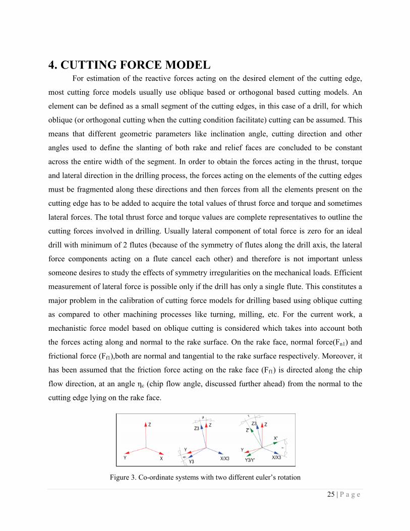
Figure 3. Co-ordinate systems with two different euler’s rotation
26 | P a g e
For a single point A on the cutting lip of a drill bit, Fig. 3 shows the two different coordinate
systems. XYZ is the global coordinate system which is associated with the drilling operation,
with the X axis showing the radial direction; the Z axis aligning with the drill axis and the Y axis
perpendicular to both the axes and corresponding to the tangential direction. Thrust forces can be
summed up by the forces acting in the direction drill axis i.e. Z-axis. Similarly torque
experienced by the drill is generated by the forces acting along the Y-axis, while lateral forces
develop along X-axis (which usually get canceled by the simultaneous action of the second flute)
The X’Y’Z’ coordinate system is affiliated with the oblique cutting element. According to it, the
Y’ axis is aligned with the local velocity vector. Here it must be pointed out that the local
velocity vector makes an angle slightly more than zero with the tangential direction i.e. Y-axis
which can be attributed to the axial feed. The X’-axis is perpendicular to the Y’ axis and lies in
the plane defined by the Y’ axis and the cutting edge. Z’ axis perpendicular to the X’Y’ plane
also including the cutting edge.
A relationship can be established between the above two coordinate systems (XYZ and X’Y’Z’)
for any point A on the cutting edge (may it be on the cutting lip area or the chisel edge region) if
the following angles are known:
- Point angle (p) described as the angle between the tool axis (or parallel to it passing through
the point A – Z axis) and the cutting edge at point A.
- Web angle (β) described as the angle at point A between X-axis and the projection of the
cutting edge onto a plane perpendicular to the axis of drilling i.e. XY plane.
- Cutting angle (μ) can be described as the angle at point A between the localized velocity vector
(V/Y’ axis) and projection of the velocity vector on a plane perpendicular to the drill axis – XY
plane. This projection is the tangential component of the velocity (Vt).
- Inclination angle (i) can be described as the angle at point A between the X’ axis (the normal to
the velocity vector (V) lying in the plane holding both the velocity vector and the cutting edge)
and the cutting edge.

27 | P a g e
In order to convert a vector {v}XYZ described in one coordinate system into another system, a
transformation matrix (also known as the direction cosine matrix no matter how it has been
derived) can be applied. It can be represented as:
' ' ', XYZ ' ' '.XYZ X Y Z X Y ZV T V
To carry out the task of transforming the vectors from one to another co-ordinate system, a
transformation matrix is formed. It is important to mention the properties of the transformation
matrices which are; their determinant is one and their transpose is equal to their inverse. This
transformation matrix from X’Y’Z’ to XYZ can be easily obtained with the help of a sequence of
Euler rotations from one system to the other. Generally a maximum of three rotations are
necessary between two arbitrary coordinate systems. For our specific case of transforming
X’Y’Z to XYZ, we need only two rotations. In fig. the required Euler rotations are represented,
where the intermediate coordinate system is X3Y3Z3 and the 2nd Euler angle of rotation is τ.
The transformation matrix(TM) from can be calculated using matrix multiplication of the two
eulers rotations as mentioned above:
TXYZ, X’Y’Z’ = TXYZ, X3Y3Z3 × T X3Y3Z3, X’Y’Z’
where,
3 3 3,XYZ X Y ZT =
3 3 3
3 3 3
3 3 3
X X X Y X
Y
Z
X Y Z
X Y
Y Y
Z Z Z Z
cos cos cos
cos cos cos
cos cos cos
As observed, X-axis is aligned with X3 thus 3X X = 0˚ and cos (
3X X ) = 1. Other angles like
angle between X and Z3 and respectively Y3 will be 90˚, and as such cosine of these angles is 0.
The remaining of the angles can be conveyed in terms of trigonometric functions of μ(r) as
follows:
3 3 3,
1 0 0 1 0 0
0 9(r) (r0 0 sin
0
)
(r) (r) si0 n9 0
XYZ X Y Z cos cos cos
cos cos s
T
co
28 | P a g e
And
3 3 3
3 3 3
3 3 3
3 3 3
' '
, ' ' ' ' '
'
'
'
' '
X X X Y X
X
Z
XY Z X Y Z Y Y Y
Z Z Z
Y Z
X Y Z
cos cos cos
cos cos cos
cos cos cos
T
Y3 is aligned with Y’ therefore cos(θY’Y3)=1(θY’Y3=0). Again angle made between Y3 (or Y’) and
Z’ and respectively X’ will still be 90˚. In other words the cosine of these angles is zero. The
remaining angles can be expressed with respect to the 2nd intermediate rotation angle ‘τ’
introduced previously from which we obtain:
3 3 3, ' ' '
0 0 sin
0 1
(r) 90 (r)
90 (r) (r) 0
0 0 0
0 sin
X Y Z X Y Z
cos cos cos
cos
cos cos cos
T
Combining the two matrixes and applying the properties of matrix, we get
' ' ', XYZ
0 sin
sin .sin( ) cos( ) .sin( )
sin .cos( ) sin( ) .cos( )
X Y Z
cos
cos
cos
T
Any vector can be used to transformed using the transformation matrix i.e. from X’Y’Z’ to the
XYZ coordinate system and its transpose is applicable to decompose from XYZ to X’Y’Z’. It is
authentic for any point on the cutting edge for any drill geometry as long as the previously
introduced angles can be determined.
Further assumptions are made that the magnitude of the forces acting on the rake face can be
introduce in the following manner.
1 .n c uF K A
11 . . .f f n f c uF K F K K A
Where empirical coefficients Kc [N/mm2]and Kf represent coefficient of specific cutting
pressure and coefficient of friction on rake face respectively. Au is uncut chip section area in a
29 | P a g e
plane at right angle to velocity vector. Point is made that the above suggested magnitude of the
cutting forces on the rake face are directly proportional to the uncut chip area (Au).
The uncut chip area Ac [mm2] is equal to: .u cA t dx
Where tc (mm) is notation for actual depth of cut which is calculated for drilling from the feed
rate, f (mm/rev), and dx (mm) is the element’s width. In drilling, elements are described with the
help of a constant size along the radial direction i.e. dr (mm).
.cos( ).cos( )cf
tN
dxcos( )
dr
After simplification the final expression is
.cos( ).uf
A drN
where N is the number of flutes
From the derivation, it is evident that while the uncut chip area Au is only influenced by the
cutting angle (μ), the actual depth of cut (tc) is also influenced by web angle (β), the 2nd Euler
rotation angle (τ) or point angle (p), and inclination angle (i) and varies significantly even in the
cutting lip region. Despite of having an influence on the chip flow angle (ηc), chip velocity, and
on the shear angle for the case of metals, the variation of the actual depth of cut (tc) with the
radius is usually ignored for the case of cutting forces modeling.
Prior proceeding to further modeling, the forces must be expressed as vectors defined in the
X’Y’Z’ coordinate system(oblique cutting).
1
n
' ' ' n
n
cos( ).sin(i)
{ } . . cos( ).cos(i)
sin( )
n X Y Z c uF K A
30 | P a g e
1
n
' ' ' n
n
.[sin( ).cos(i) cos( ).sin( ).sin(i)]
{ } . . .[cos( ).sin( ).cos(i) sin( ).sin(i)]
.[cos( ).cos( )
f c c
f X Y Z c u f c c
f c
K
F K A K
K
Utilizing vector transformation equation, the vectors are transformed into the standard drill bit
geometry system i.e. XYZ coordinate system. In drilling, the components in the Y and Z
direction (Fy and Fz )are of great interest, corresponding to tangential (torque) and axial (thrust)
loads, whereas the lateral component (Fx) is not as significant. Adding the normal force and the
frictional force acting on the rake surface transformed to XYZ coordinate system, we get
1 1 1 1
1
' ' ', XYZ ' ' ' c u 1
1
. K .A .
x
n f XYZ X Y Z n f X Y Z y
z
g
F F T F F g
g
Resultant force acting in the XYZ coordinate system can be decomposed into the three primary
axes as follows:
1 1
x
R XYZ n f XYZ y
z
F
F F F F
F
Where,
1
1
1
. .
. .
. .
x c u x
y c u y
z c u z
F K A g
F K A g
F K A g
And g1x, g1y, and g1z are geometric functions derived through matrix multiplication.
Spindle speed (n (rpm)) is not a operating parameter for the cutting forces till this point of
modeling, as the local velocity has no affect on the decomposition of the forces and geometrical
parameters of the cutting section. None the less its impact is accounted for in material property
defined earlier (the empirical coefficients (Kc and Kf)).
31 | P a g e
1 n f c c n
n f c n
cos( ). cos( ).sin(i) K .[sin( ).cos(i) cos( ).sin( )] ...
... sin( ). sin( ) K .cos( ).cos( )
xg
1 n f c c n
n f c n c
n f c n
sin( ).sin( ). cos( ).sin( ) K .[sin( ).cos(i) cos( ).sin( ).sin(i)] ...
...cos( ). cos( ).cos(i) K .[cos( )sin( ).cos(i) sin( ).sin(i)] ...
...cos( ).sin( ). sin( ) K .cos( ).cos( )
yg i
1 n f c c n
n f c n c
n f c n
sin( ).cos( ). cos( ).sin(i) K .[sin( ).cos(i) cos( ).sin( ).sin( )] ...
... sin( ). cos( ).cos(i) K .[cos( ).sin( ).cos(i) sin( ).sin(i)] ...
... cos( ).cos( ). sin( ) K .cos( ).cos( )
zg i
The total thrust (FZ (N)) and torque (MZ (N.mm)) generated during drilling can be obtained by
integrating over the required length of cutting edge in the following manner:
0
Z
.F (r).dr
M . ( ). .
r R
Z zr
y
F N
N F r r dr
Where ‘R’ is the outer radius of the drill, ‘r’ is the radial coordinate, and ‘N’ is the number of
flutes.
Derivation of certain geometry for the sake of force modeling:
[1] Point angle
A very significant characteristic of the drill, point angle can be defined as the angle of the
sweeping cone obtained by the rotation of the drill around its axis. Hence it is referred as
“point angle” (p). Drills with the cutting lips segmented (stepped drills, tapered drill
reamer, etc.) or where they are curved (e.g. racon drills), the point angle has to be defined
as functions or in stages. For the current study drills used have un-segmented and straight
cutting lips and hence have only single value assigned as the point angle.
[2] Web Angle:
The web angle (β) can be described as the angle measured between the radial direction at
point A and the cutting edge in a plane perpendicular to the drill axis, as shown in the
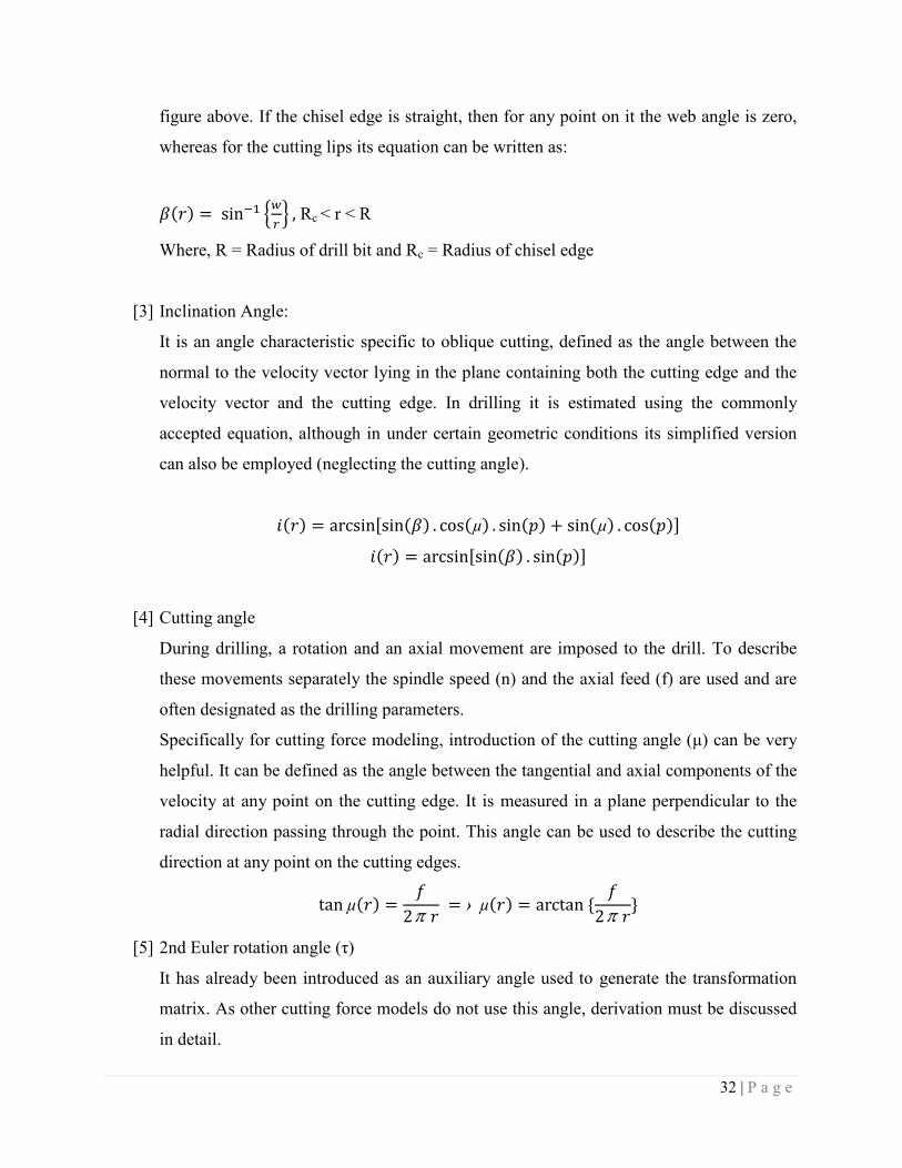
32 | P a g e
figure above. If the chisel edge is straight, then for any point on it the web angle is zero,
whereas for the cutting lips its equation can be written as:
Rc < r < R
Where, R = Radius of drill bit and Rc = Radius of chisel edge
[3] Inclination Angle:
It is an angle characteristic specific to oblique cutting, defined as the angle between the
normal to the velocity vector lying in the plane containing both the cutting edge and the
velocity vector and the cutting edge. In drilling it is estimated using the commonly
accepted equation, although in under certain geometric conditions its simplified version
can also be employed (neglecting the cutting angle).
[4] Cutting angle
During drilling, a rotation and an axial movement are imposed to the drill. To describe
these movements separately the spindle speed (n) and the axial feed (f) are used and are
often designated as the drilling parameters.
Specifically for cutting force modeling, introduction of the cutting angle (μ) can be very
helpful. It can be defined as the angle between the tangential and axial components of the
velocity at any point on the cutting edge. It is measured in a plane perpendicular to the
radial direction passing through the point. This angle can be used to describe the cutting
direction at any point on the cutting edges.
[5] 2nd Euler rotation angle (τ)
It has already been introduced as an auxiliary angle used to generate the transformation
matrix. As other cutting force models do not use this angle, derivation must be discussed
in detail.

33 | P a g e
Figure 4. Projection of element AA3 to derive 2nd euler’s angle
Assuming a small segment AA3 of the cutting edge to be unity, this segment is projected
on plane XY as shown in fig. 4. From the projection we get the triangle ∆AT3A3 (with the
<AT3A3=90˚). In this triangle the angle <AA3T3 is the point angle (p). applying simple
mathematics we get:
AT3 = sin(p)
Moreover, the angle between the X axis and AT3 is equal to the web angle (β). By
considering the triangle ∆AC1T3 (with the angle <AC1T3=90˚) and by projecting segment
AT on the X axis, we obtain:
AC1 = cos(β).sin(p)
Again, we find by the definition that the angle <C2AA3=i, where AA3 is being projected
on X’Z’ plane as AC2. Hence, from the triangle ∆AC2A3 (with the angle <AC2A3=90˚)
we can calculate AC2 as:
AC2 = cos(i)
Lastly, using the triangle ∆AC1C2, 2nd Euler angle of rotation (τ) can be calculated as:
1/AC 2
(here the angle <AC1C2=90˚)
If the web angle (β), point angle (p), and inclination angle (i) are defined, the 2nd Euler
angle of rotation can be determined for any region of the drill, with a note that it varies in
radial direction.
34 | P a g e
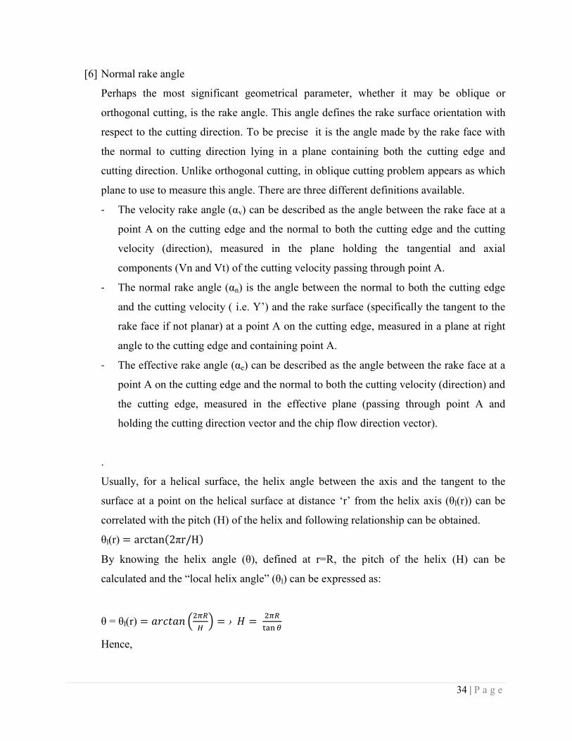
[6] Normal rake angle
Perhaps the most significant geometrical parameter, whether it may be oblique or
orthogonal cutting, is the rake angle. This angle defines the rake surface orientation with
respect to the cutting direction. To be precise it is the angle made by the rake face with
the normal to cutting direction lying in a plane containing both the cutting edge and
cutting direction. Unlike orthogonal cutting, in oblique cutting problem appears as which
plane to use to measure this angle. There are three different definitions available.
- The velocity rake angle (αv) can be described as the angle between the rake face at a
point A on the cutting edge and the normal to both the cutting edge and the cutting
velocity (direction), measured in the plane holding the tangential and axial
components (Vn and Vt) of the cutting velocity passing through point A.
- The normal rake angle (αn) is the angle between the normal to both the cutting edge
and the cutting velocity ( i.e. Y’) and the rake surface (specifically the tangent to the
rake face if not planar) at a point A on the cutting edge, measured in a plane at right
angle to the cutting edge and containing point A.
- The effective rake angle (αe) can be described as the angle between the rake face at a
point A on the cutting edge and the normal to both the cutting velocity (direction) and
the cutting edge, measured in the effective plane (passing through point A and
holding the cutting direction vector and the chip flow direction vector).
.
Usually, for a helical surface, the helix angle between the axis and the tangent to the
surface at a point on the helical surface at distance ‘r’ from the helix axis (θl(r)) can be
correlated with the pitch (H) of the helix and following relationship can be obtained.
θl(r)
By knowing the helix angle (θ), defined at r=R, the pitch of the helix (H) can be
calculated and the “local helix angle” (θl) can be expressed as:
θ = θl(r)
Hence,

35 | P a g e
θl(r)
Below we present the expression used of the normal rake angle (αn) taking into account
the cutting angle (μ).
αn

36 | P a g e
CHAPTER 5
EXPERIMENTAL DETAILS
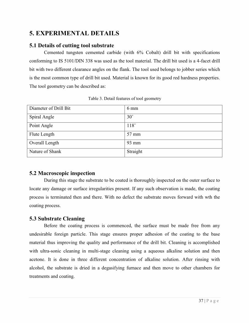
37 | P a g e
5. EXPERIMENTAL DETAILS
5.1 Details of cutting tool substrate
Cemented tungsten cemented carbide (with 6% Cobalt) drill bit with specifications
conforming to IS 5101/DIN 338 was used as the tool material. The drill bit used is a 4-facet drill
bit with two different clearance angles on the flank. The tool used belongs to jobber series which
is the most common type of drill bit used. Material is known for its good red hardness properties.
The tool geometry can be described as:
Table 3. Detail features of tool geometry
Diameter of Drill Bit 6 mm
Spiral Angle 30˚
Point Angle 118˚
Flute Length 57 mm
Overall Length 93 mm
Nature of Shank Straight
5.2 Macroscopic inspection
During this stage the substrate to be coated is thoroughly inspected on the outer surface to
locate any damage or surface irregularities present. If any such observation is made, the coating
process is terminated then and there. With no defect the substrate moves forward with wth the
coating process.
5.3 Substrate Cleaning
Before the coating process is commenced, the surface must be made free from any
undesirable foreign particle. This stage ensures proper adhesion of the coating to the base
material thus improving the quality and performance of the drill bit. Cleaning is accomplished
with ultra-sonic cleaning in multi-stage cleaning using a aqueous alkaline solution and then
acetone. It is done in three different concentration of alkaline solution. After rinsing with
alcohol, the substrate is dried in a degasifying furnace and then move to other chambers for
treatments and coating.
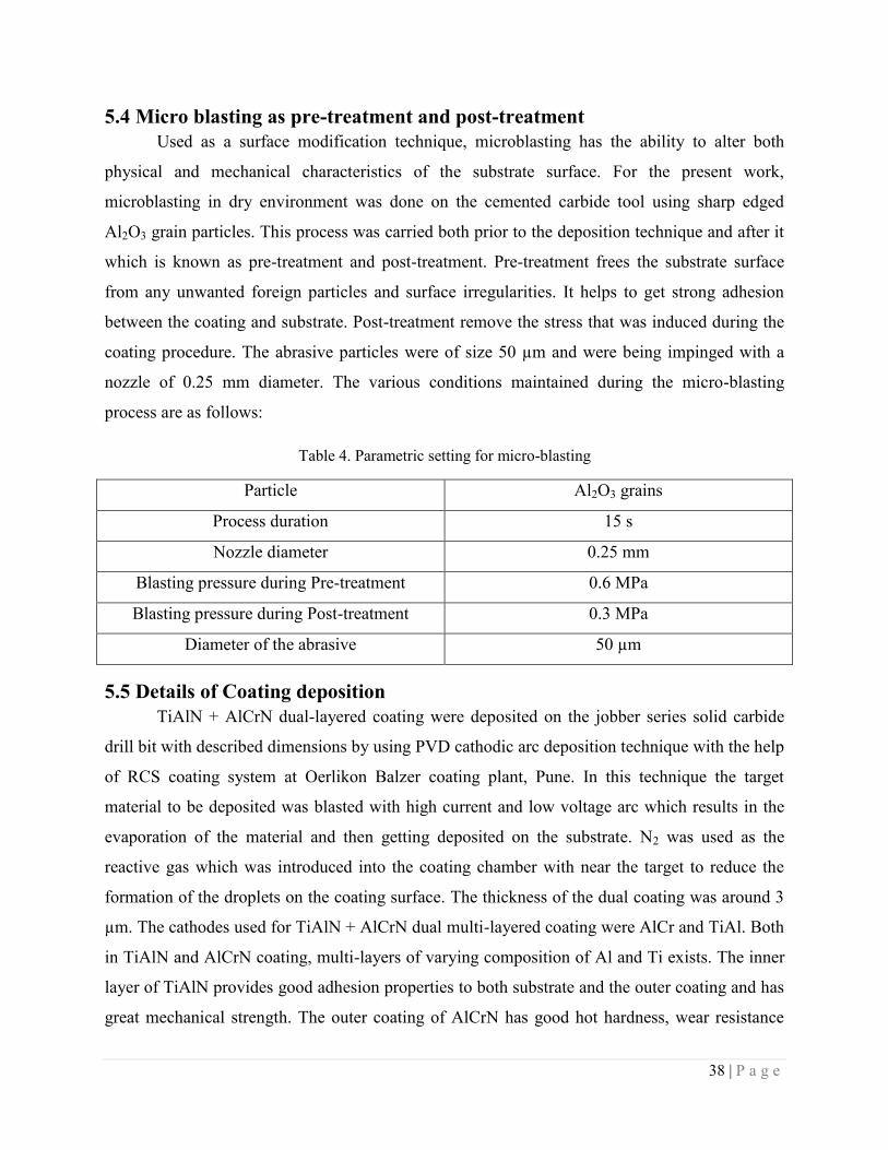
38 | P a g e
5.4 Micro blasting as pre-treatment and post-treatment
Used as a surface modification technique, microblasting has the ability to alter both
physical and mechanical characteristics of the substrate surface. For the present work,
microblasting in dry environment was done on the cemented carbide tool using sharp edged
Al2O3 grain particles. This process was carried both prior to the deposition technique and after it
which is known as pre-treatment and post-treatment. Pre-treatment frees the substrate surface
from any unwanted foreign particles and surface irregularities. It helps to get strong adhesion
between the coating and substrate. Post-treatment remove the stress that was induced during the
coating procedure. The abrasive particles were of size 50 µm and were being impinged with a
nozzle of 0.25 mm diameter. The various conditions maintained during the micro-blasting
process are as follows:
Table 4. Parametric setting for micro-blasting
Particle Al2O3 grains
Process duration 15 s
Nozzle diameter 0.25 mm
Blasting pressure during Pre-treatment 0.6 MPa
Blasting pressure during Post-treatment 0.3 MPa
Diameter of the abrasive 50 µm
5.5 Details of Coating deposition
TiAlN + AlCrN dual-layered coating were deposited on the jobber series solid carbide
drill bit with described dimensions by using PVD cathodic arc deposition technique with the help
of RCS coating system at Oerlikon Balzer coating plant, Pune. In this technique the target
material to be deposited was blasted with high current and low voltage arc which results in the
evaporation of the material and then getting deposited on the substrate. N2 was used as the
reactive gas which was introduced into the coating chamber with near the target to reduce the
formation of the droplets on the coating surface. The thickness of the dual coating was around 3
µm. The cathodes used for TiAlN + AlCrN dual multi-layered coating were AlCr and TiAl. Both
in TiAlN and AlCrN coating, multi-layers of varying composition of Al and Ti exists. The inner
layer of TiAlN provides good adhesion properties to both substrate and the outer coating and has
great mechanical strength. The outer coating of AlCrN has good hot hardness, wear resistance
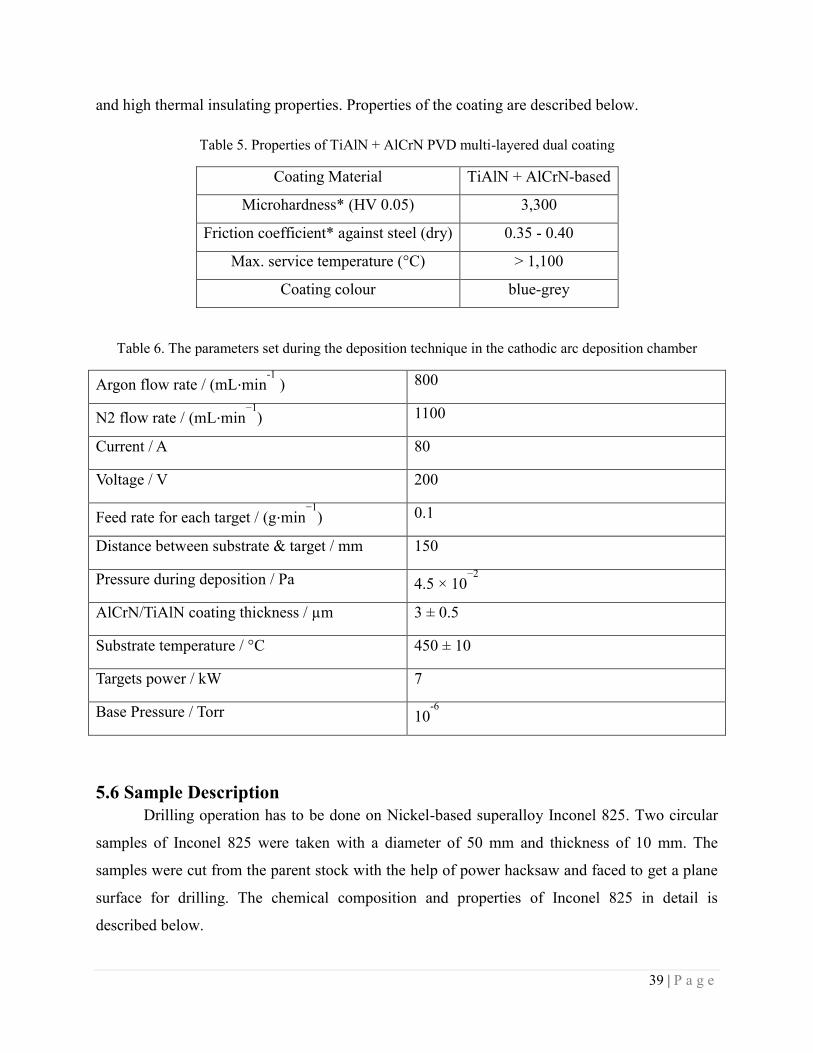
39 | P a g e
and high thermal insulating properties. Properties of the coating are described below.
Table 5. Properties of TiAlN + AlCrN PVD multi-layered dual coating
Coating Material TiAlN + AlCrN-based
Microhardness* (HV 0.05) 3,300
Friction coefficient* against steel (dry) 0.35 - 0.40
Max. service temperature (°C) > 1,100
Coating colour blue-grey
Table 6. The parameters set during the deposition technique in the cathodic arc deposition chamber
Argon flow rate / (mL⋅min-1
) 800
N2 flow rate / (mL⋅min−1
) 1100
Current / A 80
Voltage / V 200
Feed rate for each target / (g⋅min−1
) 0.1
Distance between substrate & target / mm 150
Pressure during deposition / Pa 4.5 × 10⁻²
AlCrN/TiAlN coating thickness / µm 3 ± 0.5
Substrate temperature / °C 450 ± 10
Targets power / kW 7
Base Pressure / Torr 10-6
5.6 Sample Description
Drilling operation has to be done on Nickel-based superalloy Inconel 825. Two circular
samples of Inconel 825 were taken with a diameter of 50 mm and thickness of 10 mm. The
samples were cut from the parent stock with the help of power hacksaw and faced to get a plane
surface for drilling. The chemical composition and properties of Inconel 825 in detail is
described below.
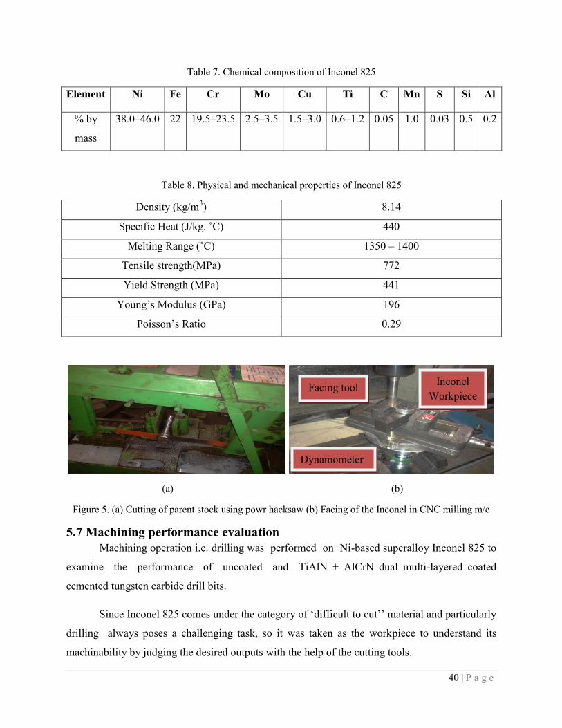
40 | P a g e
Table 7. Chemical composition of Inconel 825
Element Ni Fe Cr Mo Cu Ti C Mn S Si Al
% by
mass
38.0‒46.0 22 19.5‒23.5 2.5‒3.5 1.5‒3.0 0.6‒1.2 0.05 1.0 0.03 0.5 0.2
Table 8. Physical and mechanical properties of Inconel 825
Density (kg/m3) 8.14
Specific Heat (J/kg. ˚C) 440
Melting Range (˚C) 1350 – 1400
Tensile strength(MPa) 772
Yield Strength (MPa) 441
Young’s Modulus (GPa) 196
Poisson’s Ratio 0.29
(a) (b)
Figure 5. (a) Cutting of parent stock using powr hacksaw (b) Facing of the Inconel in CNC milling m/c
5.7 Machining performance evaluation
Machining operation i.e. drilling was performed on Ni-based superalloy Inconel 825 to
examine the performance of uncoated and TiAlN + AlCrN dual multi-layered coated
cemented tungsten carbide drill bits.
Since Inconel 825 comes under the category of ‘difficult to cut’’ material and particularly
drilling always poses a challenging task, so it was taken as the workpiece to understand its
machinability by judging the desired outputs with the help of the cutting tools.
Facing tool Inconel
Workpiece
Dynamometer
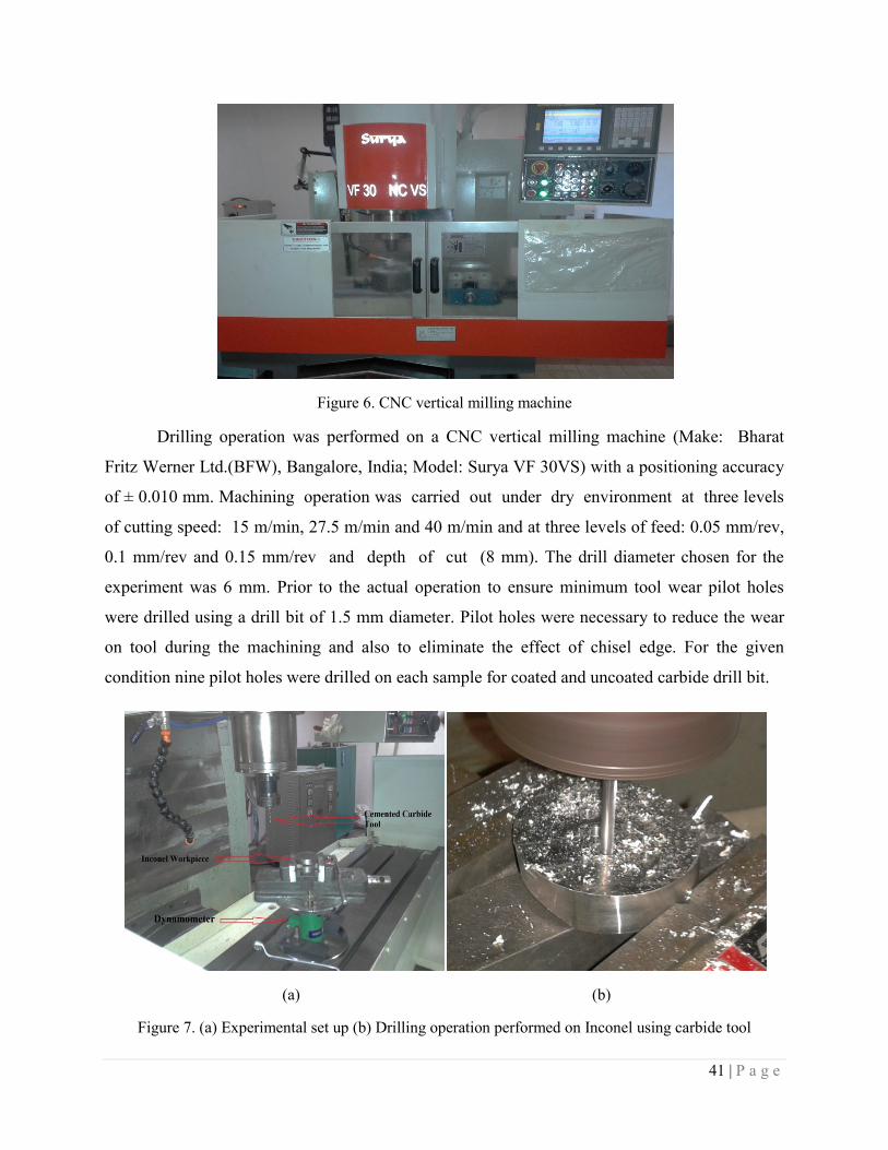
41 | P a g e
Figure 6. CNC vertical milling machine
Drilling operation was performed on a CNC vertical milling machine (Make: Bharat
Fritz Werner Ltd.(BFW), Bangalore, India; Model: Surya VF 30VS) with a positioning accuracy
of ± 0.010 mm. Machining operation was carried out under dry environment at three levels
of cutting speed: 15 m/min, 27.5 m/min and 40 m/min and at three levels of feed: 0.05 mm/rev,
0.1 mm/rev and 0.15 mm/rev and depth of cut (8 mm). The drill diameter chosen for the
experiment was 6 mm. Prior to the actual operation to ensure minimum tool wear pilot holes
were drilled using a drill bit of 1.5 mm diameter. Pilot holes were necessary to reduce the wear
on tool during the machining and also to eliminate the effect of chisel edge. For the given
condition nine pilot holes were drilled on each sample for coated and uncoated carbide drill bit.
(a) (b)
Figure 7. (a) Experimental set up (b) Drilling operation performed on Inconel using carbide tool
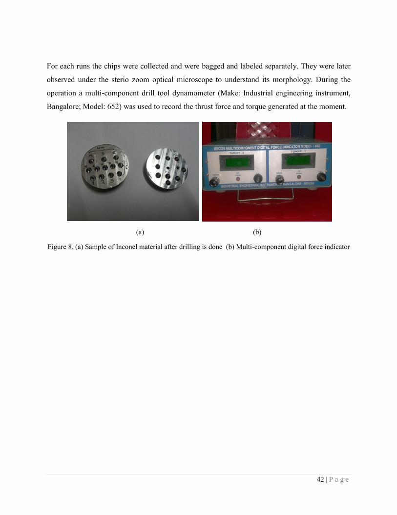
42 | P a g e
For each runs the chips were collected and were bagged and labeled separately. They were later
observed under the sterio zoom optical microscope to understand its morphology. During the
operation a multi-component drill tool dynamometer (Make: Industrial engineering instrument,
Bangalore; Model: 652) was used to record the thrust force and torque generated at the moment.
(a) (b)
Figure 8. (a) Sample of Inconel material after drilling is done (b) Multi-component digital force indicator

43 | P a g e
CHAPTER 6
SIMULATION
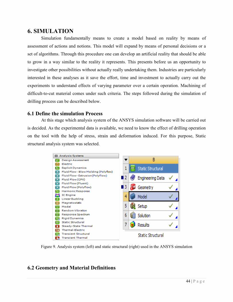
44 | P a g e
6. SIMULATION Simulation fundamentally means to create a model based on reality by means of
assessment of actions and notions. This model will expand by means of personal decisions or a
set of algorithms. Through this procedure one can develop an artificial reality that should be able
to grow in a way similar to the reality it represents. This presents before us an opportunity to
investigate other possibilities without actually really undertaking them. Industries are particularly
interested in these analyses as it save the effort, time and investment to actually carry out the
experiments to understand effects of varying parameter over a certain operation. Machining of
difficult-to-cut material comes under such criteria. The steps followed during the simulation of
drilling process can be described below.
6.1 Define the simulation Process
At this stage which analysis system of the ANSYS simulation software will be carried out
is decided. As the experimental data is available, we need to know the effect of drilling operation
on the tool with the help of stress, strain and deformation induced. For this purpose, Static
structural analysis system was selected.
Figure 9. Analysis system (left) and static structural (right) used in the ANSYS simulation
6.2 Geometry and Material Definitions
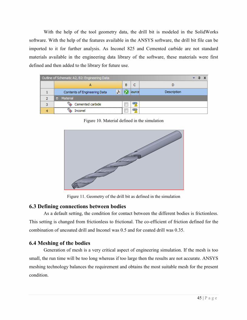
45 | P a g e
With the help of the tool geometry data, the drill bit is modeled in the SolidWorks
software. With the help of the features available in the ANSYS software, the drill bit file can be
imported to it for further analysis. As Inconel 825 and Cemented carbide are not standard
materials available in the engineering data library of the software, these materials were first
defined and then added to the library for future use.
Figure 10. Material defined in the simulation
Figure 11. Geometry of the drill bit as defined in the simulation
6.3 Defining connections between bodies
As a default setting, the condition for contact between the different bodies is frictionless.
This setting is changed from frictionless to frictional. The co-efficient of friction defined for the
combination of uncoated drill and Inconel was 0.5 and for coated drill was 0.35.
6.4 Meshing of the bodies
Generation of mesh is a very critical aspect of engineering simulation. If the mesh is too
small, the run time will be too long whereas if too large then the results are not accurate. ANSYS
meshing technology balances the requirement and obtains the most suitable mesh for the present
condition.

46 | P a g e
6.5 Define loads and boundary conditions
The thrust force and the torque generated from the experiment is applied to the cutting
edge area of the drill bit.
Figure 12. Defining the loads applied to the drill bit
6.6 Solving the model
Once all the load conditions have been decided, the output response of the simulation to
be investigated is inserted in the solution field. When solved the distribution of various responses
is observed through visual animation.
Figure 13. Solving the model and defining the output responces
6.7 Automated report generation
A complete report of the simulation process is generated which can be referred to for
analysis of data in detail.

47 | P a g e
CHAPTER 7
RESULTS AND DISCUSSION
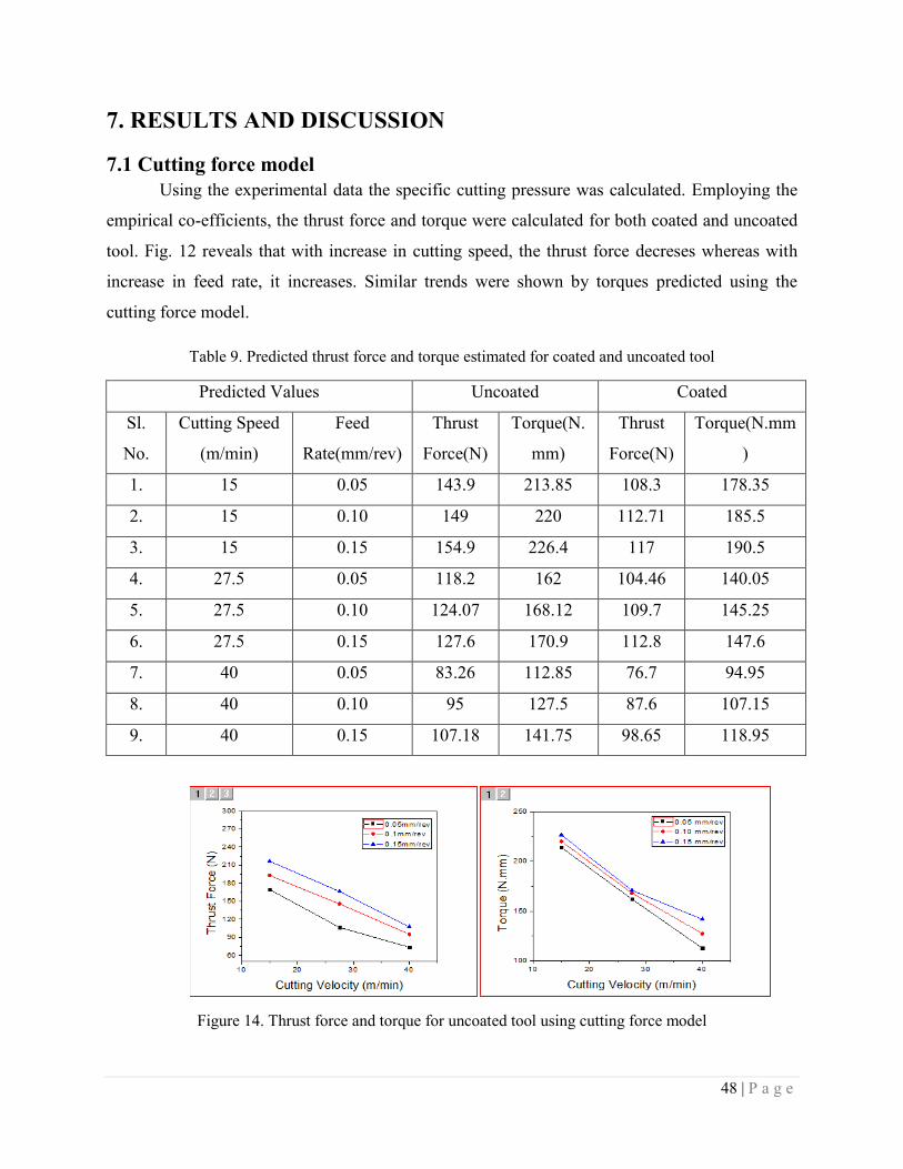
48 | P a g e
7. RESULTS AND DISCUSSION
7.1 Cutting force model
Using the experimental data the specific cutting pressure was calculated. Employing the
empirical co-efficients, the thrust force and torque were calculated for both coated and uncoated
tool. Fig. 12 reveals that with increase in cutting speed, the thrust force decreses whereas with
increase in feed rate, it increases. Similar trends were shown by torques predicted using the
cutting force model.
Table 9. Predicted thrust force and torque estimated for coated and uncoated tool
Predicted Values Uncoated Coated
Sl.
No.
Cutting Speed
(m/min)
Feed
Rate(mm/rev)
Thrust
Force(N)
Torque(N.
mm)
Thrust
Force(N)
Torque(N.mm
)
1. 15 0.05 143.9 213.85 108.3 178.35
2. 15 0.10 149 220 112.71 185.5
3. 15 0.15 154.9 226.4 117 190.5
4. 27.5 0.05 118.2 162 104.46 140.05
5. 27.5 0.10 124.07 168.12 109.7 145.25
6. 27.5 0.15 127.6 170.9 112.8 147.6
7. 40 0.05 83.26 112.85 76.7 94.95
8. 40 0.10 95 127.5 87.6 107.15
9. 40 0.15 107.18 141.75 98.65 118.95
Figure 14. Thrust force and torque for uncoated tool using cutting force model
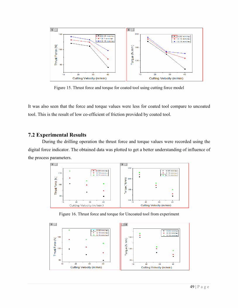
49 | P a g e
Figure 15. Thrust force and torque for coated tool using cutting force model
It was also seen that the force and torque values were less for coated tool compare to uncoated
tool. This is the result of low co-efficient of friction provided by coated tool.
7.2 Experimental Results
During the drilling operation the thrust force and torque values were recorded using the
digital force indicator. The obtained data was plotted to get a better understanding of influence of
the process parameters.
Figure 16. Thrust force and torque for Uncoated tool from experiment
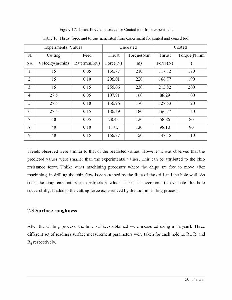
50 | P a g e
Figure 17. Thrust force and torque for Coated tool from experiment
Table 10. Thrust force and torque generated from experiment for coated and coated tool
Experimental Values Uncoated Coated
Sl.
No.
Cutting
Velocity(m/min)
Feed
Rate(mm/rev)
Thrust
Force(N)
Torque(N.m
m)
Thrust
Force(N)
Torque(N.mm
)
1. 15 0.05 166.77 210 117.72 180
2. 15 0.10 206.01 220 166.77 190
3. 15 0.15 255.06 230 215.82 200
4. 27.5 0.05 107.91 160 88.29 100
5. 27.5 0.10 156.96 170 127.53 120
6. 27.5 0.15 186.39 180 166.77 130
7. 40 0.05 78.48 120 58.86 80
8. 40 0.10 117.2 130 98.10 90
9. 40 0.15 166.77 150 147.15 110
Trends observed were similar to that of the predicted values. However it was observed that the
predicted values were smaller than the experimental values. This can be attributed to the chip
resistance force. Unlike other machining processes where the chips are free to move after
machining, in drilling the chip flow is constrained by the flute of the drill and the hole wall. As
such the chip encounters an obstruction which it has to overcome to evacuate the hole
successfully. It adds to the cutting force experienced by the tool in drilling process.
7.3 Surface roughness
After the drilling process, the hole surfaces obtained were measured using a Talysurf. Three
different set of readings surface measurement parameters were taken for each hole i.e Ra, Rt and
Rq respectively.
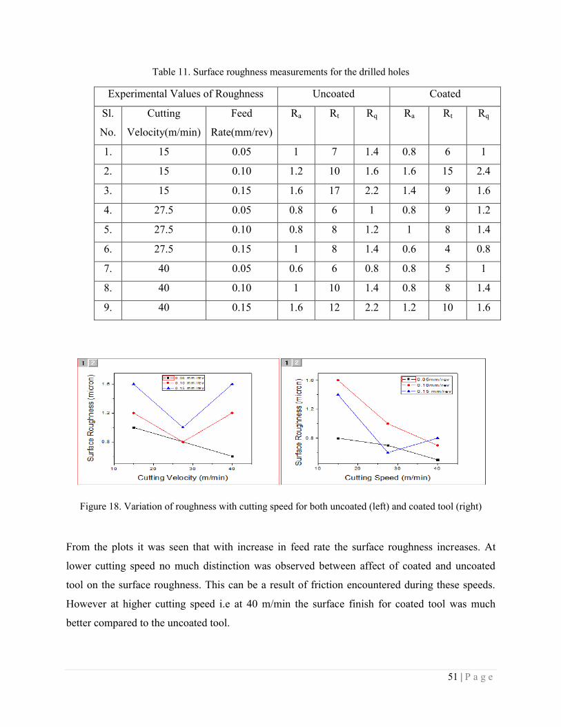
51 | P a g e
Table 11. Surface roughness measurements for the drilled holes
Experimental Values of Roughness Uncoated Coated
Sl.
No.
Cutting
Velocity(m/min)
Feed
Rate(mm/rev)
Ra Rt Rq Ra Rt Rq
1. 15 0.05 1 7 1.4 0.8 6 1
2. 15 0.10 1.2 10 1.6 1.6 15 2.4
3. 15 0.15 1.6 17 2.2 1.4 9 1.6
4. 27.5 0.05 0.8 6 1 0.8 9 1.2
5. 27.5 0.10 0.8 8 1.2 1 8 1.4
6. 27.5 0.15 1 8 1.4 0.6 4 0.8
7. 40 0.05 0.6 6 0.8 0.8 5 1
8. 40 0.10 1 10 1.4 0.8 8 1.4
9. 40 0.15 1.6 12 2.2 1.2 10 1.6
Figure 18. Variation of roughness with cutting speed for both uncoated (left) and coated tool (right)
From the plots it was seen that with increase in feed rate the surface roughness increases. At
lower cutting speed no much distinction was observed between affect of coated and uncoated
tool on the surface roughness. This can be a result of friction encountered during these speeds.
However at higher cutting speed i.e at 40 m/min the surface finish for coated tool was much
better compared to the uncoated tool.
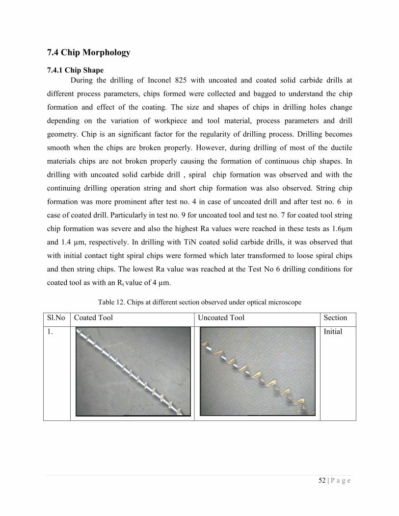
52 | P a g e
7.4 Chip Morphology
7.4.1 Chip Shape
During the drilling of Inconel 825 with uncoated and coated solid carbide drills at
different process parameters, chips formed were collected and bagged to understand the chip
formation and effect of the coating. The size and shapes of chips in drilling holes change
depending on the variation of workpiece and tool material, process parameters and drill
geometry. Chip is an significant factor for the regularity of drilling process. Drilling becomes
smooth when the chips are broken properly. However, during drilling of most of the ductile
materials chips are not broken properly causing the formation of continuous chip shapes. In
drilling with uncoated solid carbide drill , spiral chip formation was observed and with the
continuing drilling operation string and short chip formation was also observed. String chip
formation was more prominent after test no. 4 in case of uncoated drill and after test no. 6 in
case of coated drill. Particularly in test no. 9 for uncoated tool and test no. 7 for coated tool string
chip formation was severe and also the highest Ra values were reached in these tests as 1.6µm
and 1.4 µm, respectively. In drilling with TiN coated solid carbide drills, it was observed that
with initial contact tight spiral chips were formed which later transformed to loose spiral chips
and then string chips. The lowest Ra value was reached at the Test No 6 drilling conditions for
coated tool as with an Rt value of 4 µm.
Table 12. Chips at different section observed under optical microscope
Sl.No Coated Tool Uncoated Tool Section
1.
Initial
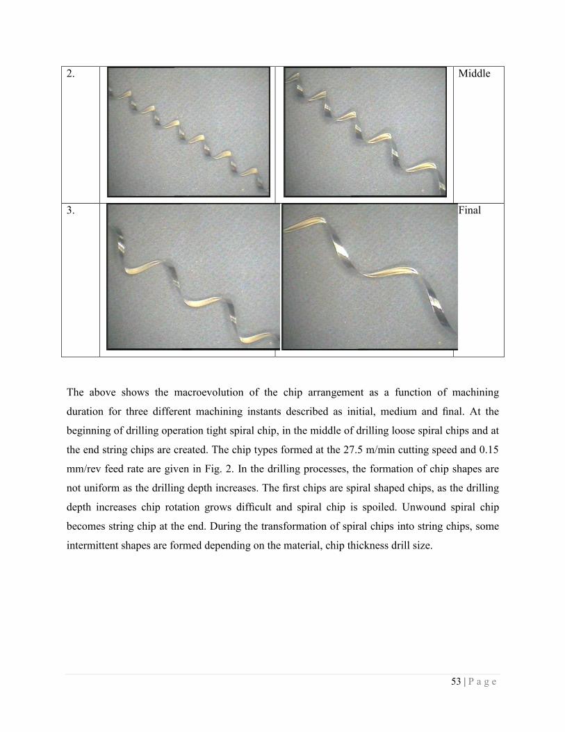
53 | P a g e
2.
Middle
3.
Final
The above shows the macroevolution of the chip arrangement as a function of machining
duration for three different machining instants described as initial, medium and final. At the
beginning of drilling operation tight spiral chip, in the middle of drilling loose spiral chips and at
the end string chips are created. The chip types formed at the 27.5 m/min cutting speed and 0.15
mm/rev feed rate are given in Fig. 2. In the drilling processes, the formation of chip shapes are
not uniform as the drilling depth increases. The first chips are spiral shaped chips, as the drilling
depth increases chip rotation grows difficult and spiral chip is spoiled. Unwound spiral chip
becomes string chip at the end. During the transformation of spiral chips into string chips, some
intermittent shapes are formed depending on the material, chip thickness drill size.
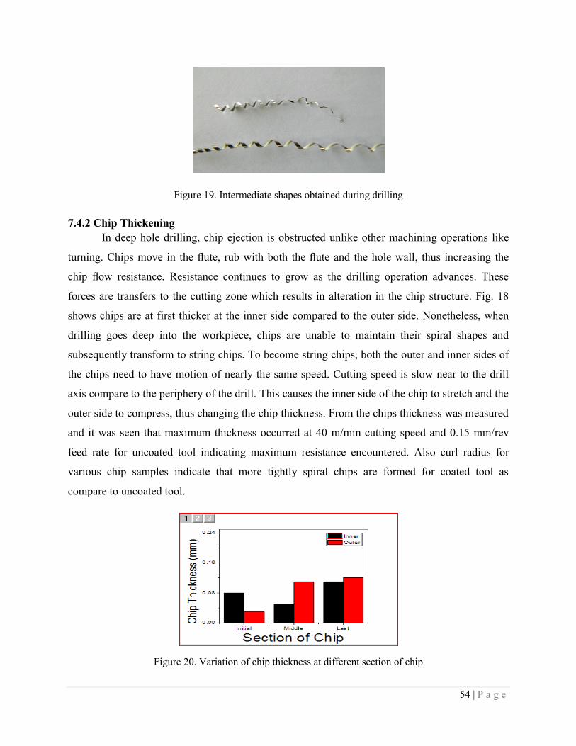
54 | P a g e
Figure 19. Intermediate shapes obtained during drilling
7.4.2 Chip Thickening
In deep hole drilling, chip ejection is obstructed unlike other machining operations like
turning. Chips move in the flute, rub with both the flute and the hole wall, thus increasing the
chip flow resistance. Resistance continues to grow as the drilling operation advances. These
forces are transfers to the cutting zone which results in alteration in the chip structure. Fig. 18
shows chips are at first thicker at the inner side compared to the outer side. Nonetheless, when
drilling goes deep into the workpiece, chips are unable to maintain their spiral shapes and
subsequently transform to string chips. To become string chips, both the outer and inner sides of
the chips need to have motion of nearly the same speed. Cutting speed is slow near to the drill
axis compare to the periphery of the drill. This causes the inner side of the chip to stretch and the
outer side to compress, thus changing the chip thickness. From the chips thickness was measured
and it was seen that maximum thickness occurred at 40 m/min cutting speed and 0.15 mm/rev
feed rate for uncoated tool indicating maximum resistance encountered. Also curl radius for
various chip samples indicate that more tightly spiral chips are formed for coated tool as
compare to uncoated tool.
Figure 20. Variation of chip thickness at different section of chip
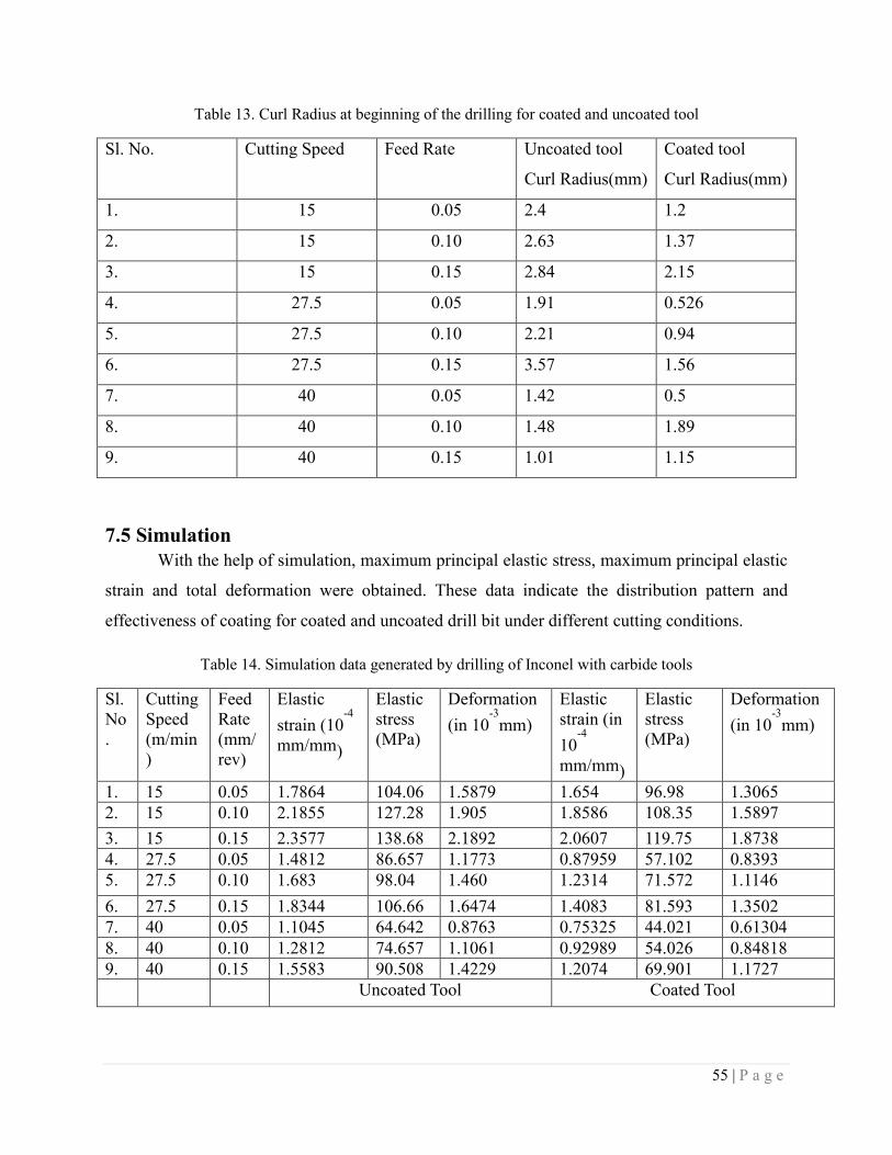
55 | P a g e
Table 13. Curl Radius at beginning of the drilling for coated and uncoated tool
Sl. No. Cutting Speed Feed Rate Uncoated tool
Curl Radius(mm)
Coated tool
Curl Radius(mm)
1. 15 0.05 2.4 1.2
2. 15 0.10 2.63 1.37
3. 15 0.15 2.84 2.15
4. 27.5 0.05 1.91 0.526
5. 27.5 0.10 2.21 0.94
6. 27.5 0.15 3.57 1.56
7. 40 0.05 1.42 0.5
8. 40 0.10 1.48 1.89
9. 40 0.15 1.01 1.15
7.5 Simulation
With the help of simulation, maximum principal elastic stress, maximum principal elastic
strain and total deformation were obtained. These data indicate the distribution pattern and
effectiveness of coating for coated and uncoated drill bit under different cutting conditions.
Table 14. Simulation data generated by drilling of Inconel with carbide tools
Sl.
No
.
Cutting
Speed
(m/min
)
Feed
Rate
(mm/
rev)
Elastic
strain (10-4
mm/mm)
Elastic
stress
(MPa)
Deformation
(in 10-3
mm)
Elastic
strain (in
10-4
mm/mm)
Elastic
stress
(MPa)
Deformation
(in 10-3
mm)
1. 15 0.05 1.7864 104.06 1.5879 1.654 96.98 1.3065
2. 15 0.10 2.1855 127.28 1.905 1.8586 108.35 1.5897
3. 15 0.15 2.3577 138.68 2.1892 2.0607 119.75 1.8738
4. 27.5 0.05 1.4812 86.657 1.1773 0.87959 57.102 0.8393
5. 27.5 0.10 1.683 98.04 1.460 1.2314 71.572 1.1146
6. 27.5 0.15 1.8344 106.66 1.6474 1.4083 81.593 1.3502
7. 40 0.05 1.1045 64.642 0.8763 0.75325 44.021 0.61304
8. 40 0.10 1.2812 74.657 1.1061 0.92989 54.026 0.84818
9. 40 0.15 1.5583 90.508 1.4229 1.2074 69.901 1.1727
Uncoated Tool Coated Tool
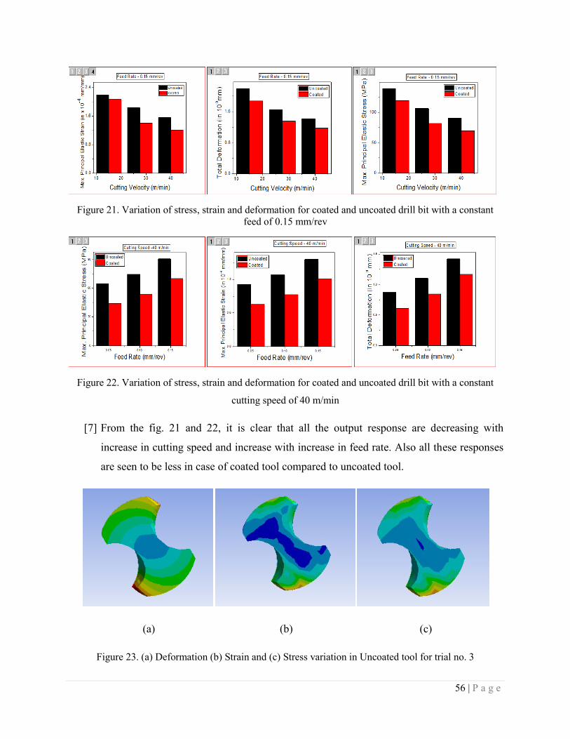
56 | P a g e
Figure 21. Variation of stress, strain and deformation for coated and uncoated drill bit with a constant
feed of 0.15 mm/rev
Figure 22. Variation of stress, strain and deformation for coated and uncoated drill bit with a constant
cutting speed of 40 m/min
[7] From the fig. 21 and 22, it is clear that all the output response are decreasing with
increase in cutting speed and increase with increase in feed rate. Also all these responses
are seen to be less in case of coated tool compared to uncoated tool.
(a) (b) (c)
Figure 23. (a) Deformation (b) Strain and (c) Stress variation in Uncoated tool for trial no. 3

57 | P a g e
Figure 24. Variation of stress in the tool

58 | P a g e
CHAPTER 8
CONCLUSION
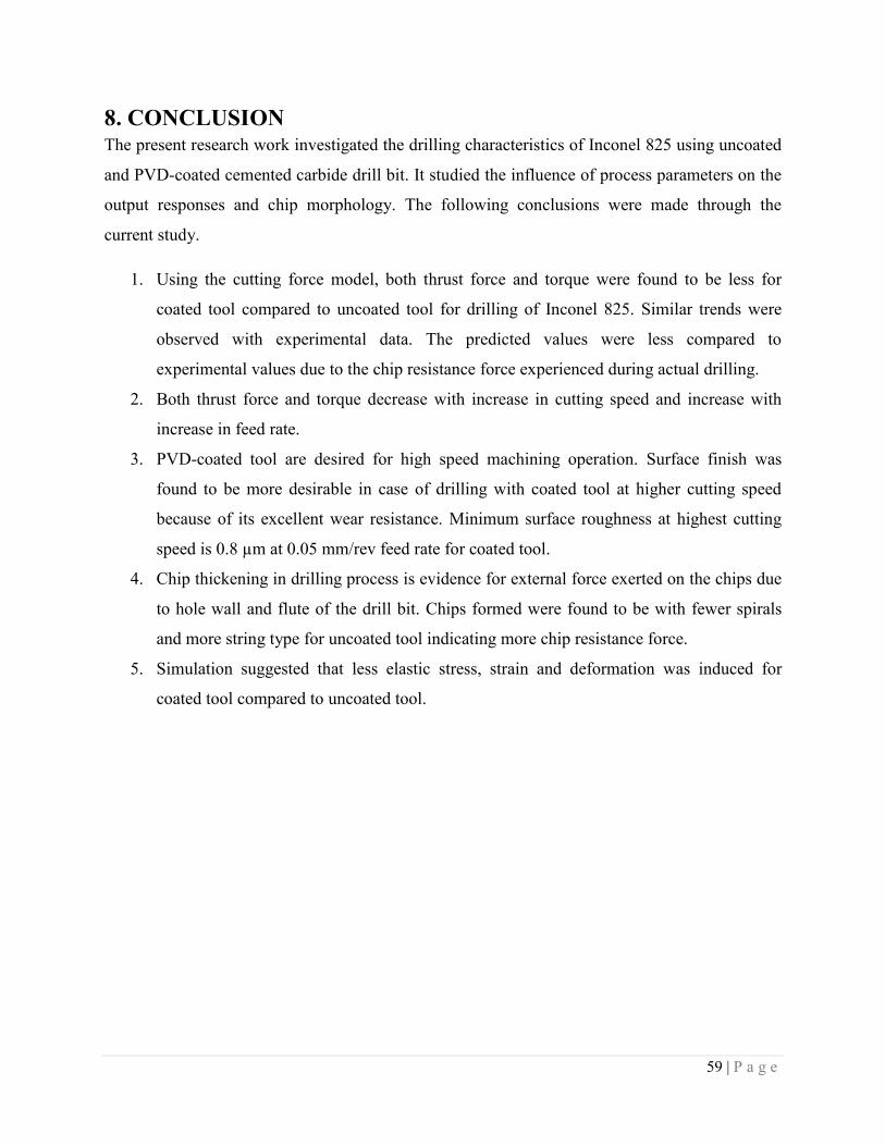
59 | P a g e
8. CONCLUSION
The present research work investigated the drilling characteristics of Inconel 825 using uncoated
and PVD-coated cemented carbide drill bit. It studied the influence of process parameters on the
output responses and chip morphology. The following conclusions were made through the
current study.
1. Using the cutting force model, both thrust force and torque were found to be less for
coated tool compared to uncoated tool for drilling of Inconel 825. Similar trends were
observed with experimental data. The predicted values were less compared to
experimental values due to the chip resistance force experienced during actual drilling.
2. Both thrust force and torque decrease with increase in cutting speed and increase with
increase in feed rate.
3. PVD-coated tool are desired for high speed machining operation. Surface finish was
found to be more desirable in case of drilling with coated tool at higher cutting speed
because of its excellent wear resistance. Minimum surface roughness at highest cutting
speed is 0.8 µm at 0.05 mm/rev feed rate for coated tool.
4. Chip thickening in drilling process is evidence for external force exerted on the chips due
to hole wall and flute of the drill bit. Chips formed were found to be with fewer spirals
and more string type for uncoated tool indicating more chip resistance force.
5. Simulation suggested that less elastic stress, strain and deformation was induced for
coated tool compared to uncoated tool.
60 | P a g e
REFERENCES [1] F.Tancret, H.K.D.H. Bhadeshia, Design of a creep resistant nickel base superalloy for
power plant applications: part 1 – Phase diagram and segregation simulation, vol. 19,
issue 3, (2003) 291-295.
[2] M.A. Amran, S. Salmah, N.I.S. Hussein, R. Izamshah, M. Hadzley, Sivaraos, M.S.
Kasim, M.A. Sulaiman, Effects of machine parameters on surface roughness using
response surface method in drilling process, The Malaysian International Tribology
Conference, Procedia Engineering 68 (2013) 24 ‒ 29.
[3] Ali Riza Motorcu, Abdil Kus, Ismail Durgun, The evaluation of the effects of control
factors on surface roughness in the drilling of Waspaloy superalloy, Measurement 58
(2014) 394–408.
[4] Nicolas Beer, Ekrem Özkaya, Dirk Biermann, Drilling of Inconel 718 with geometry-
modified twist drills, 5th Machining Innovations Conference, Procedia CIRP 24 (2014)
49 ‒ 55.
[5] J. Kwong, D.A. Axinte, P.J. Withers, The sensitivity of Ni-based superalloy to hole
making operations: Influence of process parameters on subsurface damage and residual
stress, journal of materials processing technology 209 (2009) 3968–3977.
[6] J. Kwong, D.A. Axinte, P.J. Withers, M.C. Hardy, Minor cutting edge–workpiece
interactions in drilling of an advanced nickel-based superalloy, International Journal of
Machine Tools & Manufacture 49 (2009) 645–658.
[7] Muhammad Imran, Paul T. Mativenga, Ali Gholinia, Philip J. Withers, Evaluation of
surface integrity in micro drilling process for nickel-based superalloy, Int J Adv Manuf
Technol 55 (2011) 465–476.
[8] Rachid M’Saoubi, Dragos Axinte, Christopher Herbert, Mark Hardy, Paul Salmon,
Surface integrity of nickel-based alloys subjected to severe plastic deformation by
abusive drilling, CIRP Annals - Manufacturing Technology 63 (2014) 61–64
[9] I.A. Choudhury, M.A. El-Baradie, Machinability of nickel-base super alloys: a general
review, Journal of Materials Processing Technology 77 (1998) 278–284.
[10] C.R.J. Herbert, D. A. Axinte, M.C. Hardy, P. D. Brown, Investigation into the
characteristics of white layers produced in a nickel-based superalloy from drilling
61 | P a g e
operations, 1st CIRP Conference on Surface Integrity (CSI), Procedia Engineering 19
(2011) 138 – 143.
[11] S.L. Soo, D.K. Aspinwall, R.C. Dewes, 3D FE modelling of the cutting of Inconel 718,
Journal of Materials Processing Technology 150 (2004) 116–123.
[12] A. Kortabarria, P.J. Arrazola, K. Ostolaza, Multi revolution finite element model to
predict machining induced residual stresses in Inconel 718, 14th
CIRP Conference on
Modeling of Machining Operations, Procedia CIRP 8 (2013) 111 ‒116.
[13] Feng Ke, Jun Ni, D.A. Stephenson, Chip thickening in deep-hole drilling, International
Journal of Machine Tools & Manufacture 46 (2006) 1500‒1507.
[14] Y.C. Chen, Y.S. Liao, Study on wear mechanisms in drilling of Inconel 718 superalloy,
Journal of Materials Processing Technology 140 (2003) 269–273.
[15] E.O. Ezugwu, Key improvements in the machining of difficult-to-cut aerospace
superalloys, International Journal of Machine Tools & Manufacture 45 (2005) 1353–1367.
[16] V. Schulze, F. Zanger, J.Michna, F. Lang, 3D-FE-Modelling of the Drilling Process –
Prediction of Phase Transformations at the Surface Layer, Procedia CIRP 8 ( 2013 ) 33
– 38.
[17] Sijie Yana, Dahu Zhub, Kejia Zhuanga, Xiaoming Zhanga, Han Ding, Modeling and
analysis of coated tool temperature variation in dry milling of Inconel 718 turbine blade
considering flank wear effect, Journal of Materials Processing Technology 214 (2014)
2985–3001.
[18] Z. Zhang, V.I. Babitsky, Finite element modeling of a micro-drill and experiments on
high speed ultrasonically assisted micro-drilling, Journal of Sound and Vibration 330
(2011) 2124–2137.
[19] Martin Dix, Rafael Wertheim, Gerhard Schmidt, Carsten Hochmuth, modeling of drilline
assisted by cryogenic cooling for higher efficiency, CIRP Annals- Manufacturing
Technology 63 (2014) 73-76.
[20] Amrinder Pal Singh , Dr. Manu Sharma, Modelling of Thrust Force during Drilling of
fibre reinforced Plastic Composites, Procedia Engineering 51 ( 2013 ) 630 – 636.