study on the feasibility of using non-pneumatic tyres with
TRANSCRIPT
Study on The Feasibility of using Non-Pneumatic
Tyres with Re-Entrant Type Auxetic Structured
Spokes in Cessna 172 Aircraft Tyres
Jayanthi Srivatsa Sharma1, Y Srinivas2, R. Sabari Vihar3, D. Govardhan4 Research student1, Senior Faculty2, Assistant professor3, Head of the department4, Department of
CAD/CAM, CITD, Telangana , India; Department of Aeronautical Engineering, Institute of Aeronautical
Engineering, Telangana, India
Abstract: Airless tyres or otherwise known as Non-
pneumatic tire (NPT), conveniently replaces the air which is
present in the conventional tire with flexible spokes. This
NPT overcomes the drawbacks of a pneumatic tyre like a
flat tire, blowouts, air leakage, and regular maintenance of
air pressure. The research of NPT is generally done in
Automobiles, where it is proving to fetch good results. We
have seen NPT’s being used in heavy trucks, Cars, and
Military Jeeps among many others. This project explores
the feasibility of using NPT’s in Aircraft, specifically in
Cessna 172, by analyzing the structural behavior of the
NPT with Re-Entrant Auxetic Structured spokes. This is
done by designing the model in PTC Creo and performing
Static and Modal analysis in ANSYS Workbench. The
design of NPT is based on the dimensions of a conventional
Cessna 172 tyre, but with Re-Entrant Auxetic Structured
spokes. The design consists of four main parts namely an
aluminum hub, elastic spokes (which support the vertical
load), high steel shear band, and tread (made of rubber).
The properties of these airless tyres like resistance against
rolling, contact pressure, load-bearing potential can
generally be altered by changing the designs and we will be
analyzing one such design in this paper. The results
obtained from Static Structural and Modal analysis like
Total deformation, Von-Mises Stress, Von-Mises Strain,
and Maximum Principal Stress give us an insight into how
well the design functions under loading. The results are
presented, analyzed and appropriate conclusions are
drawn. The scope for future research is also discussed.
Keyword: Non-pneumatic tyre, Re-Entrant Structure,
Auxetic Structure, Cessna 172, Total deformation, Von-
Mises Stress, Von-Mises Strain, Maximum Principal Stress,
Static Structural Analysis, Modal Analysis, PTC Creo, Ansys
Workbench.
1. INTRODUCTION Brief History
Often known аs one the greatest inventions of all
time, the wheel, revolutionized history. As a matter of
fact, the important innovation was the combination of the
wheel and a fixed axle, which enables the wheel to be
attached to a steady platform. The wheel's functionality is
severely restricted without the fixed axel. Historic
research suggests that a potter's wheel, which spins
freely and has a wheel and axle mechanism, was the first
device to employ the wheel and axle’s combination. The
first artefacts in fact were discovered in Ur, which date to
around 3150 BCE, and evidence of vehicles using wheels
may have been discovered by the late 4th millennium
BCE. Wheeled vehicles have been раrt of human
civilizations henceforth. The wheels have been
developed а lot, to suit the growing technology. It has
been а long journey from 3100 BСE to 1888 АD when
Dunlор released the first соmmerсiаl pneumatic bicycle
tyre. Pneumatic tyres have been in use ever since.
Pneumatic Tyre
Pneumatic tyres have advantages such as having low
energy loss, low vertical stiffness, low соntаct pressure
and low mass. The major disadvantages include the
роssibility of а puncture during travel, the tedious
requirement for maintaining appropriate air pressure, and
to top it off is the intricate mаnufасturing рrосess.
Because of its major impact on passenger comfort, noise,
control of vehicle, and damage, contact pressure
distribution is an important factor for designers of the
industry. Owing to the significant contact stresses, high
contact pressure causes faster tread damage. It also has a
negative impact on passenger comfort and because of its
heavy сyсliс sheаr pressure in the longitudinal and lateral
directions, high соntаct pressure differences cause faster
treаd damage. Low contact pressures, on the other hand,
makes controlling the vehicle difficult. Noise is also said
to be produced due to the uneven contact pressure. In
short, for obtaining the ideal tyre design, a suitable
contact pressure degree in addition a low contact pressure
peak is desired. These disadvantages of the pneumatic
tyre саn be transgressed using Non-Pneumatic Tyres.
Non pneumatic tyres are рrоving to be the next big things
in tyre technology.
Non-Pneumatic Tyre
These have multiple advantages such as eliminating the
роssibility of а puncture, eliminating the tedious
requirement for maintaining appropriate air pressure
аmоngst many other things. The environment also is
benefitted by using this NPT.
Since they never get punctured and саn be re-treaded,
these have a longer durability. Land fill mass will thus be
reduced greatly. This type of innovation works well and
must be considered by research and development
facilities all over the world. Airless tyres have received
International Journal of Engineering Research & Technology (IJERT)
ISSN: 2278-0181http://www.ijert.org
IJERTV10IS050467(This work is licensed under a Creative Commons Attribution 4.0 International License.)
Published by :
www.ijert.org
Vol. 10 Issue 05, May-2021
899
much interest of researchers from various research
institutes all over the world as a watershed moment in the
field of vehicle design. At large, most of these non-
pneumatic tyres are still under inspection and the
experimentation is still due . Despite the fact that
TWEEL tyres have been launched, their spokes are based
on polymer materials, which implies that they suffer
from a shorter lifespan, poor reliability, and harmful for
the environment. As a result of this, non-pneumatic tyres
made of metals has to be explored and developed.
Researchers find employing metal spokes in chiral
structures in order to further our understanding of
structural technology and to form the basic theories for
solids and the vibrational characteristics is of paramount
importance for further development. This however is the
beyond the scope of this paper. The filling of an
elastomer in place of air has been experimented by many
tire researchers who have also tried to replace air by
using polygon shaped spokes.
Many of the recent Airless tyres are seen employing a
unique flexible polygon shaped spoke. In order to find
the optimal tyre performance, there arises a need to
explore various other polygon-based geometries. After
experimenting and analyzing the various properties of
hexagonal honeycombs, including the local and macro
cellular properties, some of them were found to perform
very well with respect to the in-plane direction. Due to
their intriguing орtiсаl properties accompanied by
mechanical properties, chiral structures have piqued the
interest of many scholars lately. There are several
research findings that may be used in a variety of design
research.
A honeycomb geometry created using a tangential
соnneсtiоn of periodic ring nodes accompanied by
ligaments is known as chiral structure сhirаl structure is
one in which the ligament joined to ring nodes are on
opposite sides of the ligament where as an anti-chiral
structure is one in which the ligament joined to ring
nodes are on the same side of the ligament. The basis for
research is till the fascinating mechanical properties of
2D сhirаl structure. We have included the Аuxetiс Re-
entrant Structure in our design.
Though there have been studies on multiple designs and
their analysis, there has been little research on Non-
Pneumatic tyres with Re-entrant type auxetic structured
spokes. Apart from this, the feasibility of Non-pneumatic
tyres in aircrafts, has not been studied before. Our
research explores the possibility of using non-pneumatic
tyres with Re-entrant type auxetic structure in small
Aircraft, specifically the Cessna 172. We have conducted
Static and Modal analysis in Ansys 19.2 on a model
designed in PTC Creo parametric 7.0.2.0. The design is
based on dimensions of the Cessna 172 tyre 6.00-6
whose values were collected from the Michelin tyres
website. The dimensions of the designed parts, materials
used, force and displacements applied, etc. have been
mentioned in the Methodology. The results of the study
have been shared in the Results and Discussion section of
this paper.
2. LITERATURE REVIEW
The NPT’s have been under research for quite some
time now. Experimentation of NPT’s has been done
using different configurations with an aim to improve
their characteristics.
Jaehyung Jua, Doo-Man Kimb and Kwangwon Kimb
Kwangwon Kim b (2012) [1] conducted research and
reported their outcomes . Airless tyres (NPT) with an
appropriate solid spoke part that effectively substitutes
the usage of air in a pneumatic tyre had been presented
in here. In this work, researchers examined various
hexagonal spokes in honeycomb shape for a
configuration with higher resistance against fatigue ,
aiming for obtaining reliable hexagonal structures with
minimal local stresses . Two hexagonal honeycombs
were proposed using the mechanics involved in
honeycombs, an identical thickness of cellular wall and
an identical load bearing potential. The elastic limits of
the structures were drawn using the ABAQUS , which
took into account the nonlinearity of the structures
resulting from bending and buckling. For approving the
structure, required cell structures with relatively lower
stress values were applied to the spokes of the NPT,
and the local stresses were investigated under identical
loading scenarios. Under similar vertical load bearing
capabilities, hexagonal honeycombs with a high
positive cell angle exhibit relatively lower stresses and
bulking (the Type C spoke in honeycomb shape in this
investigation). The NPT's cellular spoke designs were
evaluated using regular and auxetic spoke in
honeycomb shapes and the related cell designs. The
notable discoveries are as follows: The in-plane
feasibility of hexagonal honeycombs is dependent on
the ratio of l to X1.The flexibility of the spokes in the
form of a honeycomb increases as the cell's angle
increases, reducing the normal force of an NPT. The
structures C and F spokes have a greater cell angle
magnitude, which results in reduced local stresses,
which is beneficial for a fatigue-resistant spoke design.
In whichever way, the spoke in honeycomb shapes of
Type C were superior in terms of resistance to fatigue
and the relatively smaller mass structure. The work
presented in my paper is an expansion of the structures
D, E, and F. We have also included a multi-layered
spoke design with a hope to obtain better results.
Mohammad Fazelpour, Joshua D. Summers(2014)[4]
discussed the advancement of meso-structures with
respect to the shear band of Michelin's non-pneumatic
tyre, the Tweel. Research scholars of the Clemson
University partnered with Michelin to aid NIST's
efforts in enhancing the fuel efficacy and in NASA's
efforts to develop human exploration technologies. The
goal of each was to supplant the shear band's
elastomeric material with materials that can tolerate
high temperatures and shear pressures, or to use linear
low-hysteretic loss materials. The ideas generated by
the ideation approach were prototyped for experimental
analysis testing. A contextual investigation analyzing
International Journal of Engineering Research & Technology (IJERT)
ISSN: 2278-0181http://www.ijert.org
IJERTV10IS050467(This work is licensed under a Creative Commons Attribution 4.0 International License.)
Published by :
www.ijert.org
Vol. 10 Issue 05, May-2021
900
the documentation reports for each task was directed to
give an intelligent comprehension of how the
development in the ventures happened.
The objective of fostering this review was to attempt to
distinguish rules and approaches that could be
incorporated into a deliberate methodology for
designing meso-structures. The development of meso-
structure enhancement for the shear band of non-
pneumatic tyres was investigated by engineers at
Clemson University between 2007 and 2010. The
structural analysis of a shear band in a non-pneumatic
tyre with meso-structure was performed. The process
started with an ideation technique, then moved on to
honeycombs, and finally presented novel designs like
the S-type meso-structure. Further research was done
for three years by a few analysts at Clemson
University who added to this progress. The study work
focused on modelling and optimization, with no
specific instructions for creating new meso-structures.
The idea to implement an auxetic structure in our
design draws inspiration from this research. A
structural analysis of airless tyres with spokes in the
form of hexagonal honeycomb structure with the same
thickness of cellular wall were examined and findings
were reported by Aravind Mohan, C Ajith Johny, A
Tamilarasu, J Pradeep Bhasker and K Ravi [3]. The
NPT with spokes shaped in honeycomb structure had a
higher magnitude of cell angle demonstrated
concentration of less stress, which is important for
resistance against fatigue. The ratio of cell height to
inclined angle of each cell was said to be a major
determinant in the construction of honeycomb
especially with respect to its feasibility under axial
stress loading scenarios. Greater flexibility and of
course feasibility are a byproduct of ratios of higher
magnitude. NPTs with spokes having hexagonal
geometries have reduced contact pressures due to
decreasing vertical rigidity with increasing load.
There are many more research paper which have
influenced our paper and are presented in the
references. The references presented support us by
providing information about nonpneumatic tyres and
the research which has been done till now. The papers
present the different ways in which the research has
been done on NPT with regards to their applications in
the Automobile Industry. We have tried to explore into
the possibility of using NPT’s in Aircrafts which has
not been studied at large till date. Though the regular
tyres of aircraft support the load and function well, the
possibility of getting deflated due to an obstacle on the
runway remains , which poses great danger. If for any
reason under inflating or over-inflating a tyre is done,
this could lead to an increase in the shear forces which
can lead to faster damage of an aircraft tyre. The
pressure differences between various tyres can
probably lead to aircrafts deviating from the runway,
separation of the shoulder of the tyre, breaking of lower
sidewall due to compression, separation of treads and
casting’s damage. Our research tries to overcome these
issues by inculcating the NPT in aircrafts The above
research has shed light as to which spoke designs prove
to be fruitful under loading conditions which has
helped us to decide upon the design configuration of
our NPT.
3. METHODOLOGY
Design
Creo is a computer-aided design (CAD) software patented
by PTC. This suite has many applications, which ease the
designing process for the designer. Creo operates on
Microsoft Windows and has apps for 3D CAD parametric,
visualization, solid modeling, technical illustrations, 3D
direct modeling, FEA , schematic design, 2D orthographic
views, and simulation. Creo Parametric and Creo Elements
go head on with CATIA, SolidWorks and Siemens Solid
Edge. The Creo software forms as the successor for the
format Pro engineering software. Creo has been in
development since 2009.In October 2010, PTC declared
that Creo would replace the former name which was
Project lightning. PTC launched Creo 1.0 in June 2011. It
creates an ecology or an interface where it can connect to
or collaborate with other softwares like Solidworks,
Siemens Nx, Windchill for Product Lifecycle Management
(PLM), Mathcad, Arbortext, etc. Thus, for its simplicity
and user-friendly interface, we had selected the Creo to
perform the design. The design is based on the dimensions
of a Cessna 172 aircraft which has an outer diameter of
about 440 mm. The four main parts of the NPT design are
:-
• ALUMINIUM HUB
• POLYURETHANE SPOKES
• HIGH STEEL OUTER RING / SHEAR BAND
• RUBBER TREAD BAND
ALUMINIUM HUB
The Hub can be fabricated by the Casting process using
(AL7075-T6) Aluminum alloy. The hub remains stationary
during the motion. The hub is associated directly with the
vehicle. This has the longest life in comparison to other
parts. The spokes of the design are bonded very strongly
with the hub to ensure that these do not separate easily. Our
hub is shown in the figure below.
Figure 3. 1 Hub
International Journal of Engineering Research & Technology (IJERT)
ISSN: 2278-0181http://www.ijert.org
IJERTV10IS050467(This work is licensed under a Creative Commons Attribution 4.0 International License.)
Published by :
www.ijert.org
Vol. 10 Issue 05, May-2021
901
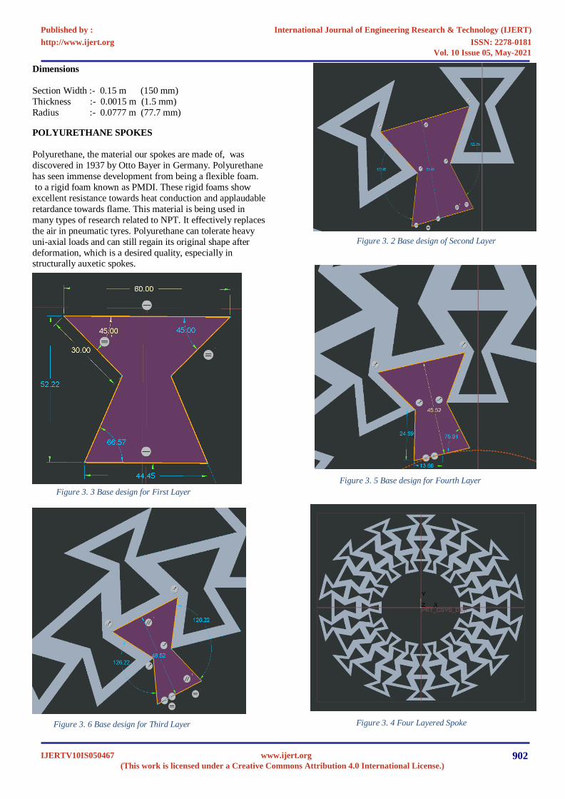
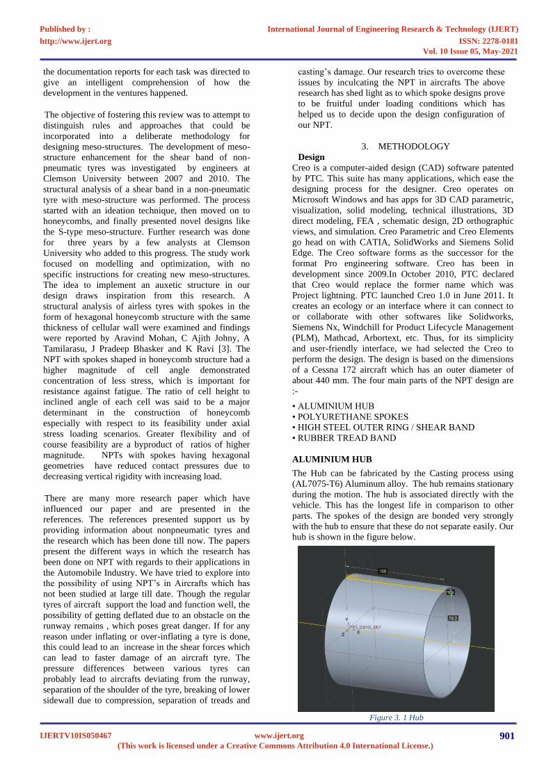
Figure 3. 3 Base design for First Layer
Figure 3. 4 Four Layered Spoke
Dimensions
Section Width :- 0.15 m (150 mm)
Thickness :- 0.0015 m (1.5 mm)
Radius :- 0.0777 m (77.7 mm)
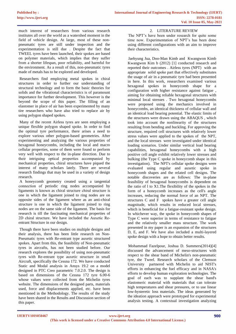
POLYURETHANE SPOKES
Polyurethane, the material our spokes are made of, was
discovered in 1937 by Otto Bayer in Germany. Polyurethane
has seen immense development from being a flexible foam.
to a rigid foam known as PMDI. These rigid foams show
excellent resistance towards heat conduction and applaudable
retardance towards flame. This material is being used in
many types of research related to NPT. It effectively replaces
the air in pneumatic tyres. Polyurethane can tolerate heavy
uni-axial loads and can still regain its original shape after
deformation, which is a desired quality, especially in structurally auxetic spokes.
Figure 3. 2 Base design of Second Layer
Figure 3. 6 Base design for Third Layer
Figure 3. 5 Base design for Fourth Layer
International Journal of Engineering Research & Technology (IJERT)
ISSN: 2278-0181http://www.ijert.org
IJERTV10IS050467(This work is licensed under a Creative Commons Attribution 4.0 International License.)
Published by :
www.ijert.org
Vol. 10 Issue 05, May-2021
902
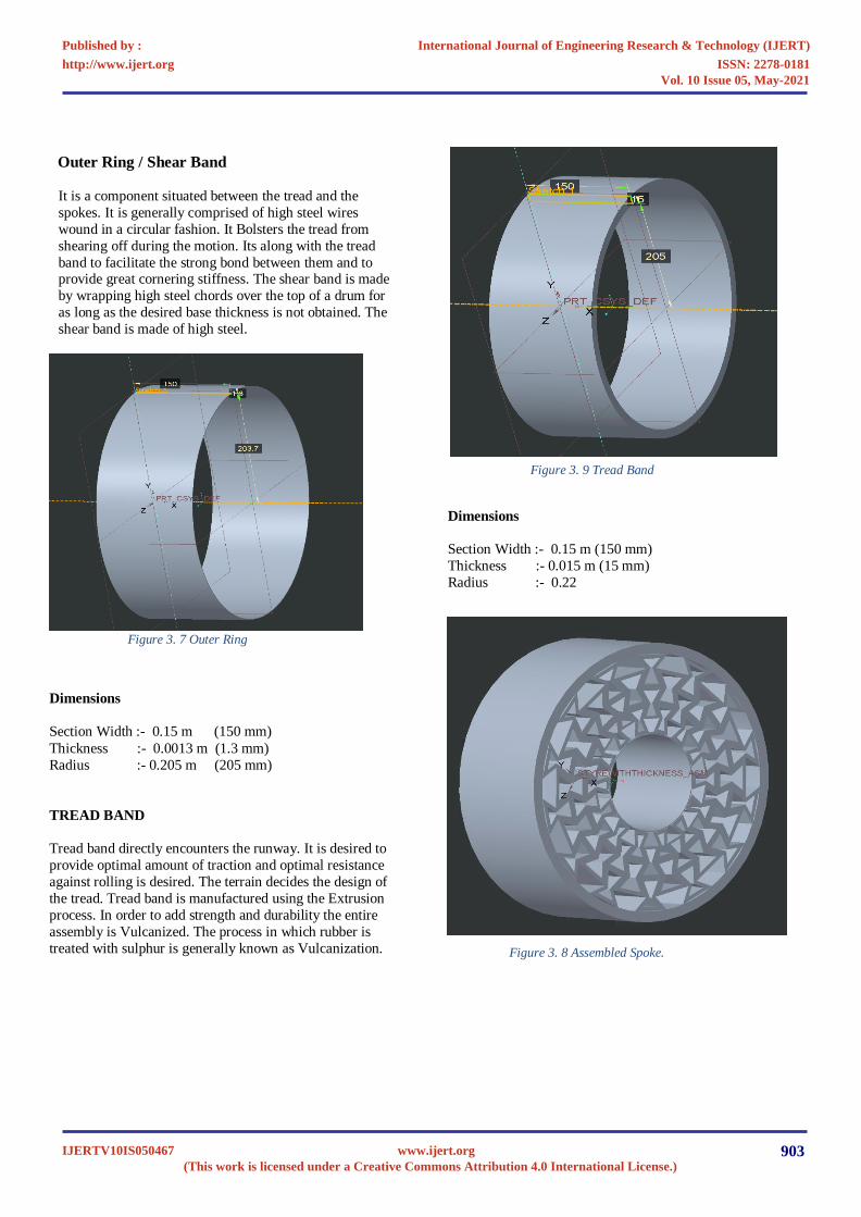
Figure 3. 8 Assembled Spoke.
Outer Ring / Shear Band
It is a component situated between the tread and the
spokes. It is generally comprised of high steel wires
wound in a circular fashion. It Bolsters the tread from
shearing off during the motion. Its along with the tread
band to facilitate the strong bond between them and to provide great cornering stiffness. The shear band is made
by wrapping high steel chords over the top of a drum for
as long as the desired base thickness is not obtained. The
shear band is made of high steel.
Figure 3. 7 Outer Ring
Dimensions
Section Width :- 0.15 m (150 mm)
Thickness :- 0.0013 m (1.3 mm)
Radius :- 0.205 m (205 mm)
TREAD BAND
Tread band directly encounters the runway. It is desired to
provide optimal amount of traction and optimal resistance
against rolling is desired. The terrain decides the design of
the tread. Tread band is manufactured using the Extrusion
process. In order to add strength and durability the entire
assembly is Vulcanized. The process in which rubber is
treated with sulphur is generally known as Vulcanization.
Dimensions
Section Width :- 0.15 m (150 mm)
Thickness :- 0.015 m (15 mm)
Radius :- 0.22
Figure 3. 9 Tread Band
International Journal of Engineering Research & Technology (IJERT)
ISSN: 2278-0181http://www.ijert.org
IJERTV10IS050467(This work is licensed under a Creative Commons Attribution 4.0 International License.)
Published by :
www.ijert.org
Vol. 10 Issue 05, May-2021
903
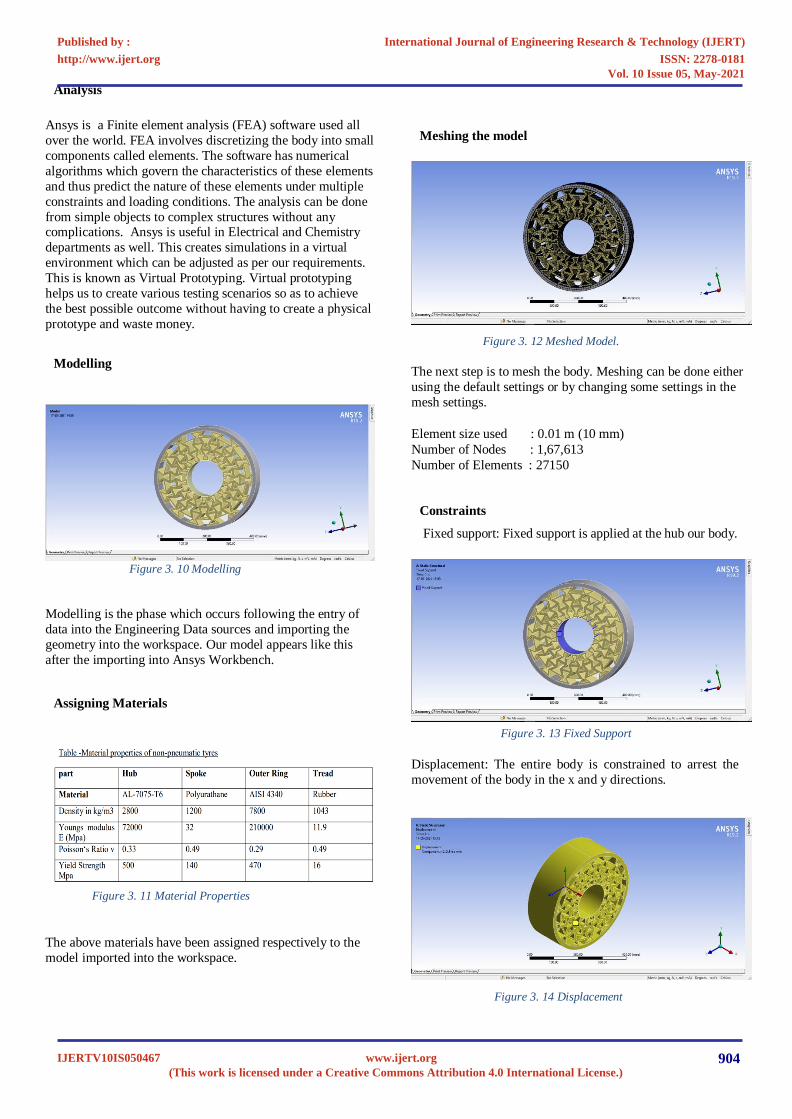
Figure 3. 11 Material Properties
Figure 3. 12 Meshed Model.
Figure 3. 13 Fixed Support
Figure 3. 14 Displacement
Analysis
Ansys is a Finite element analysis (FEA) software used all
over the world. FEA involves discretizing the body into small
components called elements. The software has numerical
algorithms which govern the characteristics of these elements
and thus predict the nature of these elements under multiple
constraints and loading conditions. The analysis can be done
from simple objects to complex structures without any complications. Ansys is useful in Electrical and Chemistry
departments as well. This creates simulations in a virtual
environment which can be adjusted as per our requirements.
This is known as Virtual Prototyping. Virtual prototyping
helps us to create various testing scenarios so as to achieve
the best possible outcome without having to create a physical
prototype and waste money.
Modelling
Figure 3. 10 Modelling
Modelling is the phase which occurs following the entry of
data into the Engineering Data sources and importing the
geometry into the workspace. Our model appears like this
after the importing into Ansys Workbench.
Assigning Materials
The above materials have been assigned respectively to the
model imported into the workspace.
Meshing the model
The next step is to mesh the body. Meshing can be done either
using the default settings or by changing some settings in the
mesh settings.
Element size used : 0.01 m (10 mm)
Number of Nodes : 1,67,613
Number of Elements : 27150
Constraints
Fixed support: Fixed support is applied at the hub our body.
Displacement: The entire body is constrained to arrest the
movement of the body in the x and y directions.
International Journal of Engineering Research & Technology (IJERT)
ISSN: 2278-0181http://www.ijert.org
IJERTV10IS050467(This work is licensed under a Creative Commons Attribution 4.0 International License.)
Published by :
www.ijert.org
Vol. 10 Issue 05, May-2021
904
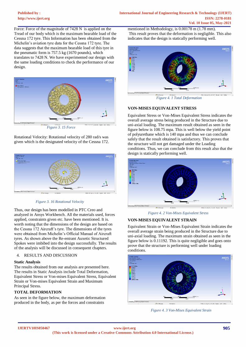
Figure 3. 15 Force
Figure 3. 16 Rotational Velocity
Figure 4. 1 Total Deformation
Figure 4. 2 Von-Mises Equivalent Stress
Force: Force of the magnitude of 7428 N is applied on the
Tread of our body which is the maximum bearable load of the
Cessna 172 tyre. This Information has been obtained from the
Michelin’s aviation tyre data for the Cessna 172 tyre. The
data suggests that the maximum bearable load of this tyre in
the pneumatic form is 757.5 kg (1670 pounds), which
translates to 7428 N. We have experimented our design with
the same loading conditions to check the performance of our
design.
Rotational Velocity: Rotational velocity of 280 rad/s was
given which is the designated velocity of the Cessna 172.
Thus, our design has been modelled in PTC Creo and
analyzed in Ansys Workbench. All the materials used, forces
applied, constraints given etc. have been mentioned. It is.
worth noting that the dimensions of the design are based on
the Cessna 172 Aircraft’s tyre. The dimensions of the tyres
were obtained from Michelin’s Official Manual of Aircraft
tyres. As shown above the Re-entrant Auxetic Structured
Spokes were imbibed into the design successfully. The results of the analysis will be discussed in consequent chapters.
4. RESULTS AND DISCUSSION
Static Analysis
The results obtained from our analysis are presented here.
The results in Static Analysis include Total Deformation,
Equivalent Stress or Von-mises Equivalent Stress, Equivalent
Strain or Von-mises Equivalent Strain and Maximum
Principal Stress.
TOTAL DEFORMATION
As seen in the figure below, the maximum deformation
produced in the body, as per the forces and constraints
mentioned in Methodology, is 0.00178 m (1.78 mm).
This result proves that the deformation is negligible. This also
indicates that the design is statically performing well.
VON-MISES EQUIVALENT STRESS
Equivalent Stress or Von-Mises Equivalent Stress indicates the
overall average stress being produced in the Structure due to uni-axial loading. The maximum result obtained as seen in the
figure below is 108.75 mpa. This is well below the yield point
of polyurethane which is 140 mpa and thus we can conclude
safely that the result obtained is satisfactory. This proves that
the structure will not get damaged under the Loading
conditions. Thus, we can conclude from this result also that the
design is statically performing well.
VON-MISES EQUIVALENT STRAIN
Equivalent Strain or Von-Mises Equivalent Strain indicates the
overall average strain being produced in the Structure due to
uni-axial loading. The maximum strain obtained as seen in the
figure below is 0.11192. This is quite negligible and goes onto
prove that the structure is performing well under loading
conditions.
Figure 4. 3 Von-Mises Equivalent Strain
International Journal of Engineering Research & Technology (IJERT)
ISSN: 2278-0181http://www.ijert.org
IJERTV10IS050467(This work is licensed under a Creative Commons Attribution 4.0 International License.)
Published by :
www.ijert.org
Vol. 10 Issue 05, May-2021
905
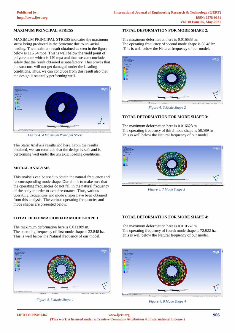
Figure 4. 4 Maximum Principal Stress
Figure 4. 5 Mode Shape 1
Figure 4. 6 Mode Shape 2
Figure 4. 7 Mode Shape 3
Figure 4. 8 Mode Shape 4
MAXIMUM PRINCIPAL STRESS
MAXIMUM PRINCIPAL STRESS indicates the maximum
stress being produced in the Structure due to uni-axial
loading. The maximum result obtained as seen in the figure
below is 115.54 mpa. This is well below the yield point of polyurethane which is 140 mpa and thus we can conclude
safely that the result obtained is satisfactory. This proves that
the structure will not get damaged under the Loading
conditions. Thus, we can conclude from this result also that
the design is statically performing well.
The Static Analysis results end here. From the results obtained, we can conclude that the design is safe and is
performing well under the uni axial loading conditions.
MODAL ANALYSIS
This analysis can be used to obtain the natural frequency and
its corresponding mode shape. Our aim is to make sure that
the operating frequencies do not fall in the natural frequency
of the body in order to avoid resonance. Thus, various
operating frequencies and mode shapes have been obtained from this analysis. The various operating frequencies and
mode shapes are presented below:
TOTAL DEFORMATION FOR MODE SHAPE 1 :
The maximum deformation here is 0.011389 m.
The operating frequency of first mode shape is 22.848 hz.
This is well below the Natural frequency of our model.
TOTAL DEFORMATION FOR MODE SHAPE 2:
The maximum deformation here is 0.016633 m.
The operating frequency of second mode shape is 58.48 hz.
This is well below the Natural frequency of our model.
TOTAL DEFORMATION FOR MODE SHAPE 3:
The maximum deformation here is 0.016623 m.
The operating frequency of third mode shape is 58.589 hz.
This is well below the Natural frequency of our model.
TOTAL DEFORMATION FOR MODE SHAPE 4:
The maximum deformation here is 0.010567 m.
The operating frequency of fourth mode shape is 72.922 hz.
This is well below the Natural frequency of our model.
International Journal of Engineering Research & Technology (IJERT)
ISSN: 2278-0181http://www.ijert.org
IJERTV10IS050467(This work is licensed under a Creative Commons Attribution 4.0 International License.)
Published by :
www.ijert.org
Vol. 10 Issue 05, May-2021
906
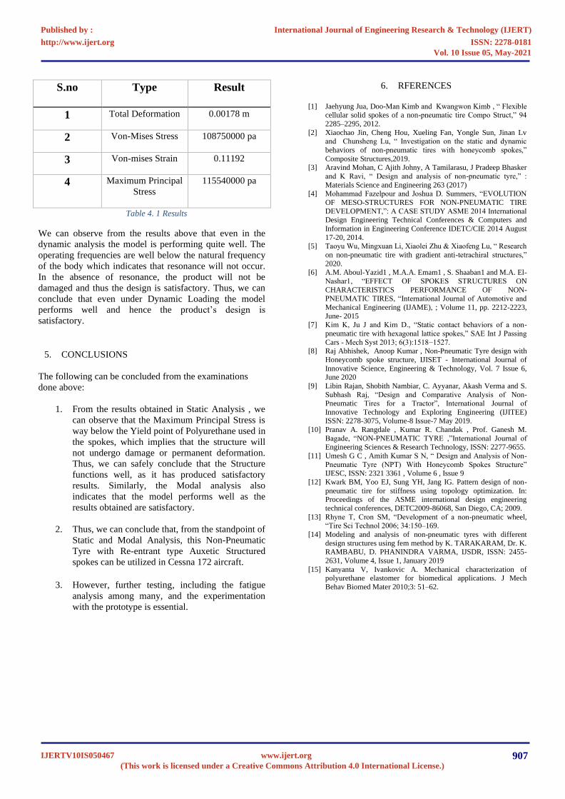
S.no
Type Result
1 Total Deformation
0.00178 m
2 Von-Mises Stress
108750000 pa
3 Von-mises Strain
0.11192
4 Maximum Principal
Stress
115540000 pa
Table 4. 1 Results
We can observe from the results above that even in the
dynamic analysis the model is performing quite well. The
operating frequencies are well below the natural frequency
of the body which indicates that resonance will not occur.
In the absence of resonance, the product will not be
damaged and thus the design is satisfactory. Thus, we can
conclude that even under Dynamic Loading the model
performs well and hence the product’s design is
satisfactory.
5. CONCLUSIONS
The following can be concluded from the examinations
done above:
1. From the results obtained in Static Analysis , we
can observe that the Maximum Principal Stress is
way below the Yield point of Polyurethane used in
the spokes, which implies that the structure will
not undergo damage or permanent deformation.
Thus, we can safely conclude that the Structure
functions well, as it has produced satisfactory
results. Similarly, the Modal analysis also
indicates that the model performs well as the
results obtained are satisfactory.
2. Thus, we can conclude that, from the standpoint of
Static and Modal Analysis, this Non-Pneumatic
Tyre with Re-entrant type Auxetic Structured
spokes can be utilized in Cessna 172 aircraft.
3. However, further testing, including the fatigue
analysis among many, and the experimentation
with the prototype is essential.
6. RFERENCES
[1] Jaehyung Jua, Doo-Man Kimb and Kwangwon Kimb , “ Flexible
cellular solid spokes of a non-pneumatic tire Compo Struct,” 94
2285–2295, 2012.
[2] Xiaochao Jin, Cheng Hou, Xueling Fan, Yongle Sun, Jinan Lv and Chunsheng Lu, “ Investigation on the static and dynamic
behaviors of non-pneumatic tires with honeycomb spokes,”
Composite Structures,2019. [3] Aravind Mohan, C Ajith Johny, A Tamilarasu, J Pradeep Bhasker
and K Ravi, “ Design and analysis of non-pneumatic tyre,” :
Materials Science and Engineering 263 (2017) [4] Mohammad Fazelpour and Joshua D. Summers, “EVOLUTION
OF MESO-STRUCTURES FOR NON-PNEUMATIC TIRE
DEVELOPMENT,”: A CASE STUDY ASME 2014 International Design Engineering Technical Conferences & Computers and
Information in Engineering Conference IDETC/CIE 2014 August
17-20, 2014. [5] Taoyu Wu, Mingxuan Li, Xiaolei Zhu & Xiaofeng Lu, “ Research
on non-pneumatic tire with gradient anti-tetrachiral structures,”
2020. [6] A.M. Aboul-Yazid1 , M.A.A. Emam1 , S. Shaaban1 and M.A. El-
Nashar1, “EFFECT OF SPOKES STRUCTURES ON
CHARACTERISTICS PERFORMANCE OF NON-PNEUMATIC TIRES, “International Journal of Automotive and
Mechanical Engineering (IJAME), ; Volume 11, pp. 2212-2223,
June- 2015 [7] Kim K, Ju J and Kim D., “Static contact behaviors of a non-
pneumatic tire with hexagonal lattice spokes,” SAE Int J Passing
Cars - Mech Syst 2013; 6(3):1518−1527. [8] Raj Abhishek, Anoop Kumar , Non-Pneumatic Tyre design with
Honeycomb spoke structure, IJISET - International Journal of
Innovative Science, Engineering & Technology, Vol. 7 Issue 6, June 2020
[9] Libin Rajan, Shobith Nambiar, C. Ayyanar, Akash Verma and S.
Subhash Raj, “Design and Comparative Analysis of Non-Pneumatic Tires for a Tractor”, International Journal of
Innovative Technology and Exploring Engineering (IJITEE)
ISSN: 2278-3075, Volume-8 Issue-7 May 2019.
[10] Pranav A. Rangdale , Kumar R. Chandak , Prof. Ganesh M.
Bagade, “NON-PNEUMATIC TYRE ,”International Journal of Engineering Sciences & Research Technology, ISSN: 2277-9655.
[11] Umesh G C , Amith Kumar S N, “ Design and Analysis of Non-
Pneumatic Tyre (NPT) With Honeycomb Spokes Structure” IJESC, ISSN: 2321 3361 , Volume 6 , Issue 9
[12] Kwark BM, Yoo EJ, Sung YH, Jang IG. Pattern design of non-
pneumatic tire for stiffness using topology optimization. In: Proceedings of the ASME international design engineering
technical conferences, DETC2009-86068, San Diego, CA; 2009.
[13] Rhyne T, Cron SM, “Development of a non-pneumatic wheel, “Tire Sci Technol 2006; 34:150–169.
[14] Modeling and analysis of non-pneumatic tyres with different
design structures using fem method by K. TARAKARAM, Dr. K. RAMBABU, D. PHANINDRA VARMA, IJSDR, ISSN: 2455-
2631, Volume 4, Issue 1, January 2019
[15] Kanyanta V, Ivankovic A. Mechanical characterization of polyurethane elastomer for biomedical applications. J Mech
Behav Biomed Mater 2010;3: 51–62.
International Journal of Engineering Research & Technology (IJERT)
ISSN: 2278-0181http://www.ijert.org
IJERTV10IS050467(This work is licensed under a Creative Commons Attribution 4.0 International License.)
Published by :
www.ijert.org
Vol. 10 Issue 05, May-2021
907