subsea technology hfl systems - walther praezision
TRANSCRIPT
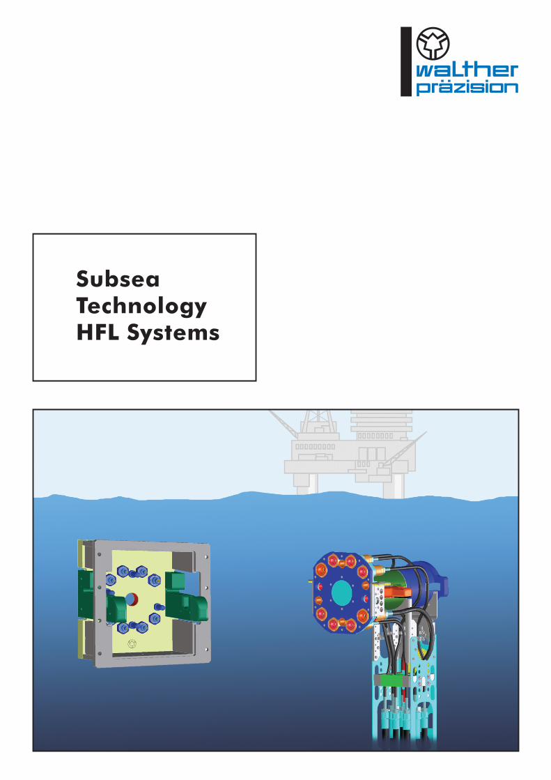
Subsea TechnologyHFL Systems
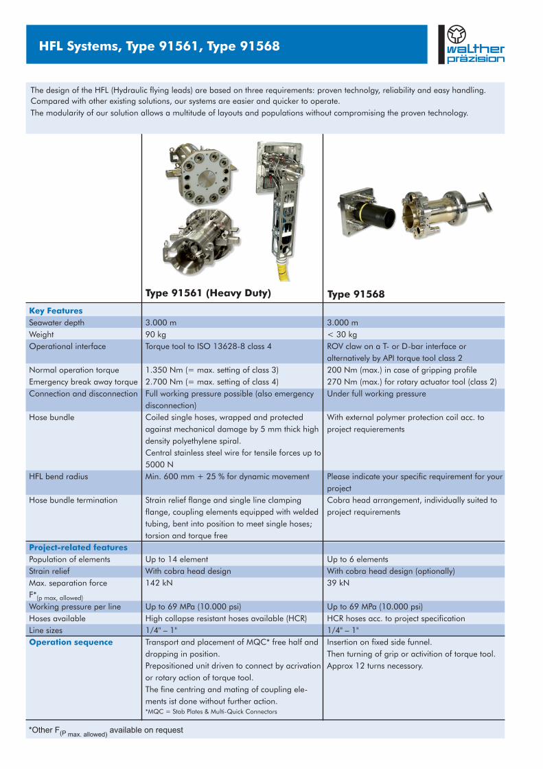
Type 91568Type 91561 (Heavy Duty)
HFL Systems, Type 91561, Type 91568 HFL Systems, Type 91561, Type 91568
Hose specifications for Type 91561, sample (Please indicate your specific requirement for your project!)
Self sealing elements
1/4"
3/8"
1/2"
3/4"
1"
69 (10.000)
69 (10.000)
69 (10.000)
69 (10.000)
56 (8.120)
350 (50.750)
350 (50.750)
325 (47.125)
250 (3.625)
225 (3.262)
150
190
200
250
300
0,31
0,47
0,94
1,46
2,00
Core materialPressure
reinforcement
High
strength
wire
Cover
PA 12
black
OM-006
OM-010
OM-016
1/4 "; 3/8"
1/2"
3/4"; 1"
69
69 (10.000)
69 (10.000)
(10.000) 90
215
435
Suitablefor line size
Working pressure WP [MPa, (PSI)]max
Surface S element [mm²]
Working pressure
[MPa, (PSI)]
Burst pressure
[MPa, (PSI)]
Minimum bend radius
[mm] Weight in air
[kg/m] Diameter
Population - Determination
F [kN] = (S [mm²] • WP [MPa])P (specific) element n element n
with: F* > F ; WP < WP P (max. allowed) P (specific) element n max *Other F available on request (P max. allowed)
å
Geometrical restraints might apply! Please use our service for a feasibility check.
Size
Methanol
washed
PA 11
Part number
91561-B-00004-AAAI-Y01
91561-B-00007-AAAJ-Y01
91561-2-FT004-AAAE-Y01
91561-0-LT004-AAAL-Y03-AA
91561-2-FT004-AAAK-Y02-AA
91561-0-LT005-AAAN-Y04-AA
91568-0-LT001-AAAD-Y04-AC
91568-2-FT002-AAAB-Y02-AB
91568-5-AAAC-Y02
91568-9-FT002-AAAF-Y04-AC
91568-2-FT002-AAAE-Y04-AC
91568-0-LT001-AAAA-Y03-AB
Specification (Please indicate your specific requirement for you project!)
HFL 8 way, jumper length 5 metres, ROV stab plates on both ends (other lengths available)
HFL 8 way, jumper length 15 metres, ROV stab plate on one end (other lengths available)
Receptacle, tube tail termination
Simplified free half stab plate to test and flush receptacles
Simplified fixed half stab plate to test and flush HFL
Cross over free half (picture see on reverse)
ROV side stab plate, 5-way for OM-006 elements, D-bar handle
Receptacle side, 4-way for OM-006 elements, adaptor side
Protection cap for receptacles
Parking station for 5-way stab plate
Receptacle side, 5-way for OM-006 elements, adaptor side
ROV side stab plate, 4-way for OM-006 elements, T-bar handle
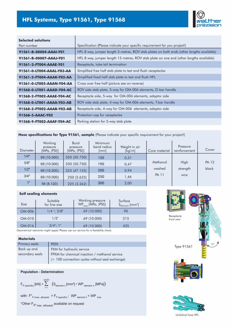
Type 9156145°
Receptacle front view
specific
n=1
3.000 m
90 kg
Torque tool to ISO 13628-8 class 4
1.350 Nm (= max. setting of class 3)
2.700 Nm (= max. setting of class 4)
Full working pressure possible (also emergency
disconnection)
Coiled single hoses, wrapped and protected
against mechanical damage by 5 mm thick high
density polyethylene spiral.
Central stainless steel wire for tensile forces up to
5000 N
Min. 600 mm + 25 % for dynamic movement
Strain relief flange and single line clamping
flange, coupling elements equipped with welded
tubing, bent into position to meet single hoses;
torsion and torque free
Up to 14 element
With cobra head design
142 kN
Up to 69 MPa (10.000 psi)
High collapse resistant hoses available (HCR)
1/4" – 1"
Transport and placement of MQC* free half and
dropping in position.
Prepositioned unit driven to connect by acrivation
or rotary action of torque tool.
The fine centring and mating of coupling ele-
ments ist done without further action.*MQC = Stab Plates & Multi-Quick Connectors
3.000 m
< 30 kg
ROV claw on a T- or D-bar interface or
alternatively by API torque tool class 2
200 Nm (max.) in case of gripping profile
270 Nm (max.) for rotary actuator tool (class 2)
Under full working pressure
With external polymer protection coil acc. to
project requierements
Please indicate your specific requirement for your
project
Cobra head arrangement, individually suited to
project requirements
Up to 6 elements
With cobra head design (optionally)
Up to 69 MPa (10.000 psi)
HCR hoses acc. to project specification
1/4" – 1"
Insertion on fixed side funnel.
Then turning of grip or activition of torque tool.
Approx 12 turns necessory.
39 kN
Key Features
Project-related features
Operation sequence
Seawater depth
Weight
Operational interface
Normal operation torque
Emergency break away torque
Connection and disconnection
Hose bundle
HFL bend radius
Hose bundle termination
Population of elements
Strain relief
Max. separation force
F*(p max, allowed)
Working pressure per line
Hoses available
Line sizes
Umbilical hose HFL
Materials
Primary seals
Back up and
secondary seals
PEEK
FKM for hydraulic service
FFKM for chemical injection / methanol service
(> 100 connection cycles without seal exchange)
*Other F available on request (P max. allowed)
The design of the HFL (Hydraulic flying leads) are based on three requirements: proven technolgy, reliability and easy handling.
Compared with other existing solutions, our systems are easier and quicker to operate.
The modularity of our solution allows a multitude of layouts and populations without compromising the proven technology.
Selected solutions
Type 91568Type 91561 (Heavy Duty)
HFL Systems, Type 91561, Type 91568 HFL Systems, Type 91561, Type 91568
Hose specifications for Type 91561, sample (Please indicate your specific requirement for your project!)
Self sealing elements
1/4"
3/8"
1/2"
3/4"
1"
69 (10.000)
69 (10.000)
69 (10.000)
69 (10.000)
56 (8.120)
350 (50.750)
350 (50.750)
325 (47.125)
250 (3.625)
225 (3.262)
150
190
200
250
300
0,31
0,47
0,94
1,46
2,00
Core materialPressure
reinforcement
High
strength
wire
Cover
PA 12
black
OM-006
OM-010
OM-016
1/4 "; 3/8"
1/2"
3/4"; 1"
69
69 (10.000)
69 (10.000)
(10.000) 90
215
435
Suitablefor line size
Working pressure WP [MPa, (PSI)]max
Surface S element [mm²]
Working pressure
[MPa, (PSI)]
Burst pressure
[MPa, (PSI)]
Minimum bend radius
[mm] Weight in air
[kg/m] Diameter
Population - Determination
F [kN] = (S [mm²] • WP [MPa])P (specific) element n element n
with: F* > F ; WP < WP P (max. allowed) P (specific) element n max *Other F available on request (P max. allowed)
å
Geometrical restraints might apply! Please use our service for a feasibility check.
Size
Methanol
washed
PA 11
Part number
91561-B-00004-AAAI-Y01
91561-B-00007-AAAJ-Y01
91561-2-FT004-AAAE-Y01
91561-0-LT004-AAAL-Y03-AA
91561-2-FT004-AAAK-Y02-AA
91561-0-LT005-AAAN-Y04-AA
91568-0-LT001-AAAD-Y04-AC
91568-2-FT002-AAAB-Y02-AB
91568-5-AAAC-Y02
91568-9-FT002-AAAF-Y04-AC
91568-2-FT002-AAAE-Y04-AC
91568-0-LT001-AAAA-Y03-AB
Specification (Please indicate your specific requirement for you project!)
HFL 8 way, jumper length 5 metres, ROV stab plates on both ends (other lengths available)
HFL 8 way, jumper length 15 metres, ROV stab plate on one end (other lengths available)
Receptacle, tube tail termination
Simplified free half stab plate to test and flush receptacles
Simplified fixed half stab plate to test and flush HFL
Cross over free half (picture see on reverse)
ROV side stab plate, 5-way for OM-006 elements, D-bar handle
Receptacle side, 4-way for OM-006 elements, adaptor side
Protection cap for receptacles
Parking station for 5-way stab plate
Receptacle side, 5-way for OM-006 elements, adaptor side
ROV side stab plate, 4-way for OM-006 elements, T-bar handle
Type 9156145°
Receptacle front view
specific
n=1
3.000 m
90 kg
Torque tool to ISO 13628-8 class 4
1.350 Nm (= max. setting of class 3)
2.700 Nm (= max. setting of class 4)
Full working pressure possible (also emergency
disconnection)
Coiled single hoses, wrapped and protected
against mechanical damage by 5 mm thick high
density polyethylene spiral.
Central stainless steel wire for tensile forces up to
5000 N
Min. 600 mm + 25 % for dynamic movement
Strain relief flange and single line clamping
flange, coupling elements equipped with welded
tubing, bent into position to meet single hoses;
torsion and torque free
Up to 14 element
With cobra head design
142 kN
Up to 69 MPa (10.000 psi)
High collapse resistant hoses available (HCR)
1/4" – 1"
Transport and placement of MQC* free half and
dropping in position.
Prepositioned unit driven to connect by acrivation
or rotary action of torque tool.
The fine centring and mating of coupling ele-
ments ist done without further action.*MQC = Stab Plates & Multi-Quick Connectors
3.000 m
< 30 kg
ROV claw on a T- or D-bar interface or
alternatively by API torque tool class 2
200 Nm (max.) in case of gripping profile
270 Nm (max.) for rotary actuator tool (class 2)
Under full working pressure
With external polymer protection coil acc. to
project requierements
Please indicate your specific requirement for your
project
Cobra head arrangement, individually suited to
project requirements
Up to 6 elements
With cobra head design (optionally)
Up to 69 MPa (10.000 psi)
HCR hoses acc. to project specification
1/4" – 1"
Insertion on fixed side funnel.
Then turning of grip or activition of torque tool.
Approx 12 turns necessory.
39 kN
Key Features
Project-related features
Operation sequence
Seawater depth
Weight
Operational interface
Normal operation torque
Emergency break away torque
Connection and disconnection
Hose bundle
HFL bend radius
Hose bundle termination
Population of elements
Strain relief
Max. separation force
F*(p max, allowed)
Working pressure per line
Hoses available
Line sizes
Umbilical hose HFL
Materials
Primary seals
Back up and
secondary seals
PEEK
FKM for hydraulic service
FFKM for chemical injection / methanol service
(> 100 connection cycles without seal exchange)
*Other F available on request (P max. allowed)
The design of the HFL (Hydraulic flying leads) are based on three requirements: proven technolgy, reliability and easy handling.
Compared with other existing solutions, our systems are easier and quicker to operate.
The modularity of our solution allows a multitude of layouts and populations without compromising the proven technology.
Selected solutions
Subsea TechnologyHFL Systems
Hausadresse / Head office: Postadresse / Postal address:
Telefon: +49 (0) 21 29 567-0Telefax: +49 (0) 21 29 567-450
eMail: [email protected]: www.walther-praezision.de
Westfalenstraße 242781 Haan, Germany
Postfach 42044442404 Haan, Germany
WALTHER-PRÄZISIONCarl Kurt Walther GmbH & Co. KG
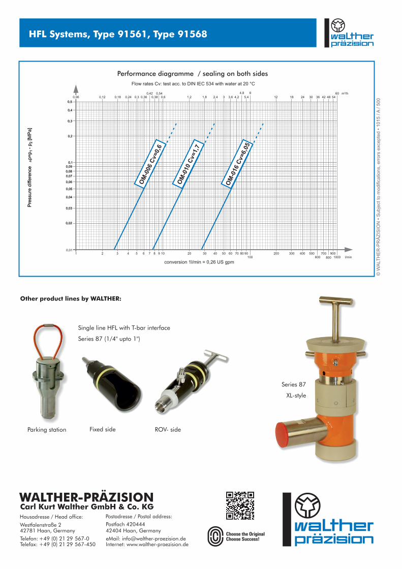
Performance diagramme / sealing on both sides
Flow rates Cv: test acc. to DIN IEC 534 with water at 20 °C
conversion 1l/min = 0,26 US gpm
2
0,12 0,18 0,24 0,3 0,36 0,38 0,6 1,2 1,8 2,4 3 3,6 4,2 5,4 12 18 24 30 36 42 48 54
360 m /h4,8 60,42 0,54
0,020,02
20 20010,01
3
0,030,03
0,040,04
0,050,05
0,060,06
0,070,07
0,080,08
0,090,090,10,1
0,20,2
0,30,3
0,40,4
0,50,5
30 3004 40 4005 50 5006 60600
7 70 7008 80
800
9 90 90010100 1000 l/min
0,06
Pre
ssu
re d
iffe
ren
ce ª
p=
p-
p
1
2[M
Pa
] P
ress
ure
diff
ere
nce
ª
p=
p-
p
1
2[M
Pa
]
OM
-006
Cv=
0,6
OM
-010
Cv=
1,7
OM
-016
Cv=
6,05
HFL Systems, Type 91561, Type 91568
© W
ALT
HE
R-P
RÄ
ZIS
ION
• S
ub
ject
to
mo
difi
catio
ns,
err
ors
exc
ep
ted
• 1
01
5 / A
/ 5
00
Parking station
Series 87
XL-style
Fixed side ROV- side
Single line HFL with T-bar interface
Series 87 (1/4" upto 1")
Other product lines by WALTHER: