sug/u 1.1 split unit gateway · chapter 1 . general . chapter 2 : device technology . ... tool can...
TRANSCRIPT

— PRODUCT MANUAL
ABB i-bus® KNX SUG/U 1.1 Split Unit Gateway


ABB i-bus® KNX Contents
SUG/U 1.1 | 2CDC508171D0201 i
Contents Page
1 General ................................................................................................. 3 1.1 Using the product manual .............................................................................................................3 1.1.1 Notes ............................................................................................................................................4 1.2 Overview of product and functions ...............................................................................................5 1.2.1 Integration in the i-bus® Tool ........................................................................................................6
2 Device technology ............................................................................... 7 2.1 Technical data ..............................................................................................................................7 2.2 Connection diagram .....................................................................................................................9 2.3 Dimension drawing ..................................................................................................................... 10 2.4 Mounting and installation ............................................................................................................ 11
3 Commissioning .................................................................................. 13 3.1 Overview..................................................................................................................................... 13 3.2 Parameters ................................................................................................................................. 15 3.2.1 General parameter window......................................................................................................... 16 3.2.2 Split Unit settings parameter window .......................................................................................... 20 3.2.3 Functions parameter window ...................................................................................................... 26
Forced operation parameter window .......................................................................................... 28 Window contact parameter window ............................................................................................ 29 Presence parameter window ...................................................................................................... 30 Scenes parameter window ......................................................................................................... 31 Boost parameter window ............................................................................................................ 33
3.2.4 Status objects parameter window ............................................................................................... 34 3.3 Group objects ............................................................................................................................. 36 3.3.1 Summary of group objects .......................................................................................................... 36 3.3.2 Group objects ............................................................................................................................. 37 3.4 Special operating states ............................................................................................................. 45 3.4.1 Reaction on bus voltage failure .................................................................................................. 45 3.4.2 Reaction on bus voltage recovery .............................................................................................. 45 3.4.3 Reaction on ETS download ........................................................................................................ 45 3.4.4 Reaction on ETS reset ............................................................................................................... 46
A Appendix ............................................................................................ 47 A.1 Code table, 8 bit scene ............................................................................................................... 47 A.2 Ordering details .......................................................................................................................... 48 A.3 Open source components........................................................................................................... 49 A.4 Notes .......................................................................................................................................... 50

ABB i-bus® KNX General
SUG/U 1.1 | 2CDC508171D0201 3
1 General
This manual provides detailed technical information concerning the ABB i-bus® KNX SUG/U 1.1 Split Unit Gateway.
Split units are HVAC devices which are usually operated by an infrared remote control. The Split Unit Gateway is installed near the split unit and the transmitter of the supplied cable is bonded to the receiver of the unit itself. This makes it possible to control the split unit via KNX group commands. The Split Unit Gateway allows users to integrate the split unit in a KNX system for convenient, energy efficient control.
1.1 Using the product manual
This manual provides detailed technical information on the function, installation and programming of the ABB i-bus® KNX device. Explanations on how to use it are accompanied by examples.
This manual is divided into the following chapters:
Chapter 1 General
Chapter 2 Device technology
Chapter 3 Commissioning
Chapter A Appendix

ABB i-bus® KNX General
4 2CDC508171D0201 | SUG/U 1.1
1.1.1 Notes
Notes and safety instructions are represented as follows in this manual:
Note
Tips for usage and operation
Examples
Application examples, installation examples, programming examples
Important
These safety instructions are used as soon as there is danger of a malfunction without risk of damage or injury.
Caution These safety instructions are used as soon as there is danger of a malfunction without risk of damage or injury.
Danger These safety instructions are used if there is a danger to life and limb with inappropriate use.
Danger These safety instructions are used if there is an extreme danger to life with inappropriate use.
ABB i-bus® KNX General
SUG/U 1.1 | 2CDC508171D0201 5
1.2 Overview of product and functions
The Split Unit Gateway forms the interface between the KNX system and climate control equipment from a wide range of manufacturers, also referred to as split units. The device converts KNX telegrams to infrared commands and sends them to the split unit.
The Split Unit Gateway is installed near the split unit and the transmitter of the supplied cable is bonded to the receiver of the unit itself. Thereafter, the climate control equipment no longer receives commands from a remote control but instead can be operated via any KNX sensors or via a visual display.
The split unit's functions can therefore be operated via KNX using any operating element. The available functions are as follows:
• On/Off
• Specify setpoint temperature including parametrizable setpoint temperature limits
• Set operating mode (Automatic, Heating, Cooling, Ventilation, Drying)
• Fan speed control
• Horizontal and vertical swing
• Activate Silent Mode
In addition, the following functions can be parametrized via KNX:
• Forced operation
• Window contact
• Presence
• Scene
• Boost function

ABB i-bus® KNX General
6 2CDC508171D0201 | SUG/U 1.1
1.2.1 Integration in the i-bus® Tool
The device possesses an interface to the i-bus® Tool.
The i-bus® Tool can be used to read out data and test functions on the connected device.
The i-bus® Tool can be downloaded free from our website (www.abb.com/knx).
ETS is not required for the software tool.
A description of the functions is provided in the i-bus® Tool online help.
Note
Not all of the device's functions can be operated using the i-bus® Tool. Priorities (Forced operation and Window contact) and the Presence function can only be activated/deactivated via the bus. If a priority is active, the device cannot be operated with the i-bus® Tool. If the connection drops between the device and the i-bus® Tool, the device maintains the last state that was set. In other words, commands from the i-bus® Tool and KNX telegrams have equal priority (exception: priorities).
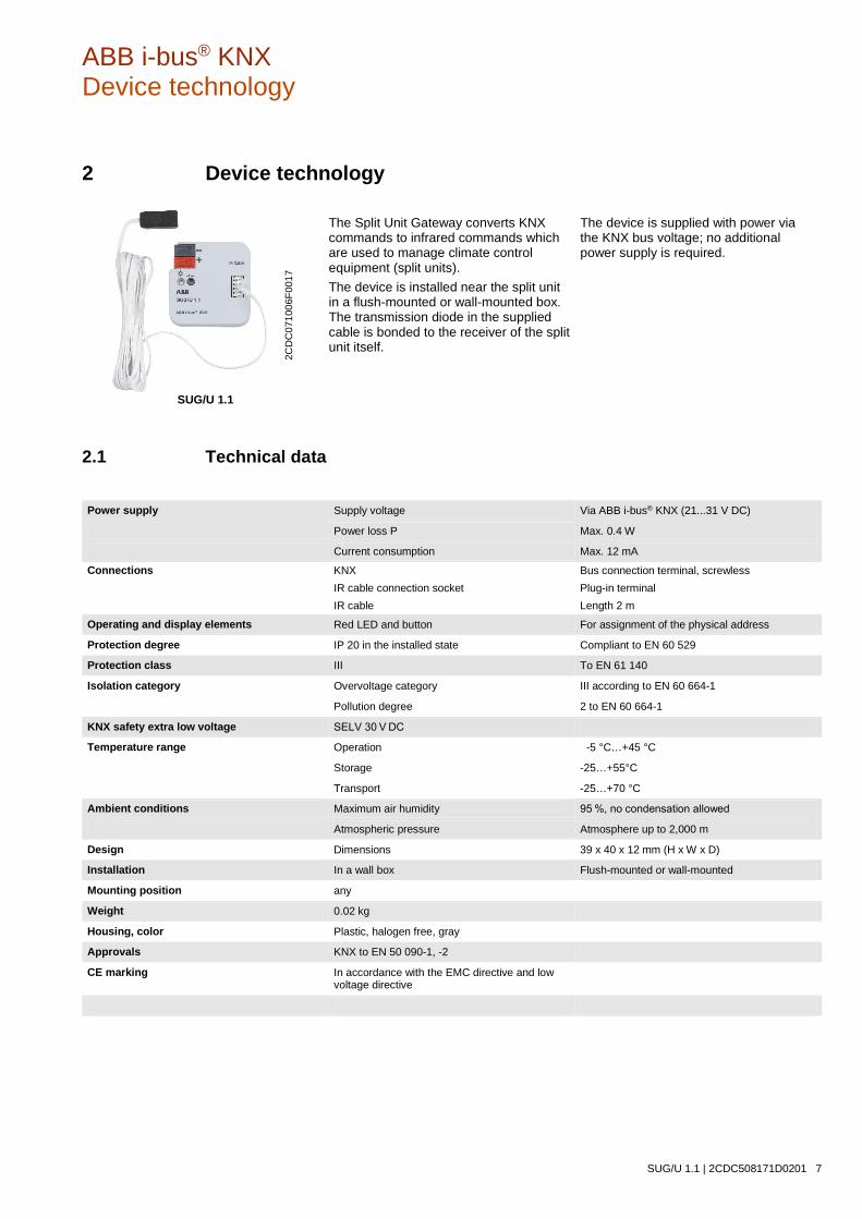
ABB i-bus® KNX Device technology
SUG/U 1.1 | 2CDC508171D0201 7
2 Device technology
SUG/U 1.1
The Split Unit Gateway converts KNX commands to infrared commands which are used to manage climate control equipment (split units). The device is installed near the split unit in a flush-mounted or wall-mounted box. The transmission diode in the supplied cable is bonded to the receiver of the split unit itself.
The device is supplied with power via the KNX bus voltage; no additional power supply is required.
2.1 Technical data
Power supply Supply voltage Via ABB i-bus® KNX (21...31 V DC)
Power loss P Max. 0.4 W
Current consumption Max. 12 mA
Connections KNX Bus connection terminal, screwless IR cable connection socket Plug-in terminal IR cable Length 2 m
Operating and display elements Red LED and button For assignment of the physical address
Protection degree IP 20 in the installed state Compliant to EN 60 529
Protection class III To EN 61 140
Isolation category Overvoltage category III according to EN 60 664-1
Pollution degree 2 to EN 60 664-1
KNX safety extra low voltage SELV 30 V DC
Temperature range Operation -5 °C…+45 °C
Storage -25…+55°C
Transport -25…+70 °C
Ambient conditions Maximum air humidity 95 %, no condensation allowed
Atmospheric pressure Atmosphere up to 2,000 m
Design Dimensions 39 x 40 x 12 mm (H x W x D)
Installation In a wall box Flush-mounted or wall-mounted
Mounting position any
Weight 0.02 kg
Housing, color Plastic, halogen free, gray
Approvals KNX to EN 50 090-1, -2
CE marking In accordance with the EMC directive and low voltage directive
2CD
C07
1006
F001
7

ABB i-bus® KNX Device technology
8 2CDC508171D0201 | SUG/U 1.1
Device type Application Maximum number of group objects
Maximum number of group addresses
Maximum number of assignments
SUG/U 1.1 Split Unit Gateway/…* 30 255 255
* … = Current version number of the application. Please refer to the software information on our website for this purpose.
Note
The Engineering Tool Software, ETS, version 4.2.0, 5.5.3 or later, and the current device application are required for programming. The current application is available for download on the Internet at www.abb.com/knx along with the corresponding software information. After import into ETS it appears in the Catalogs window under Manufacturers/ABB/Heating Ventilation Air conditioning. The device does not support the locking function of a KNX device in ETS. Using a BCU code to inhibit access to all the project devices has no effect on this device. Data can still be read and programmed.

ABB i-bus® KNX Device technology
SUG/U 1.1 | 2CDC508171D0201 9
2.2 Connection diagram
1 Bus connection terminal
2 IR cable connection socket
3 Programming LED
4 Programming button
2CD
C07
2019
F001
6 2C
DC
0730
01F0
017
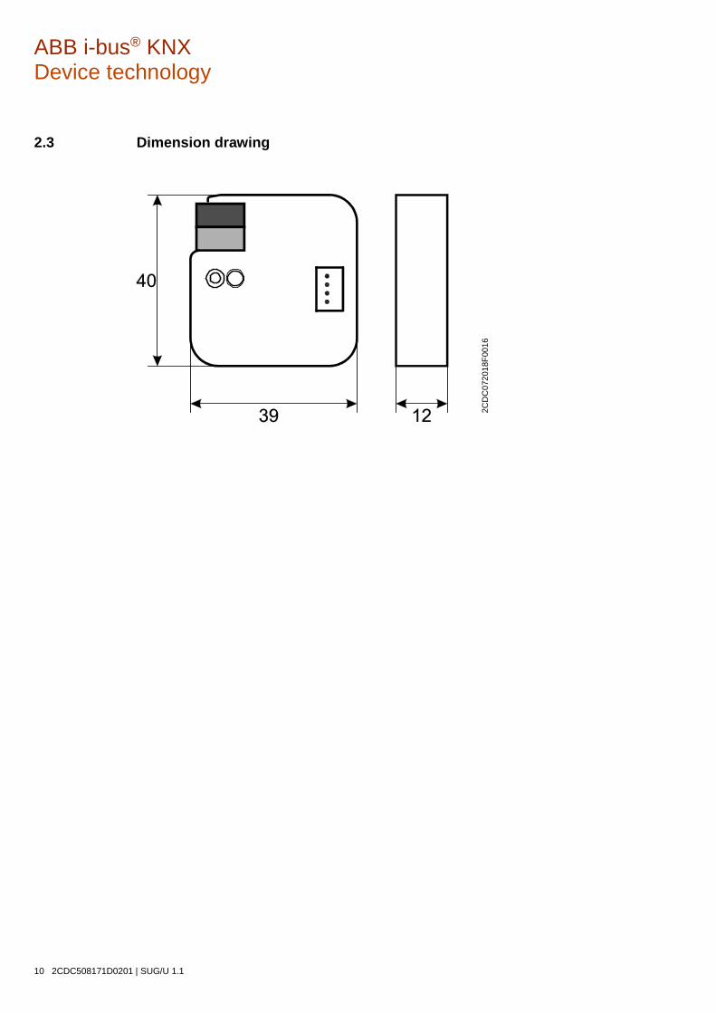
ABB i-bus® KNX Device technology
10 2CDC508171D0201 | SUG/U 1.1
2.3 Dimension drawing
2CD
C07
2018
F001
6

ABB i-bus® KNX Device technology
SUG/U 1.1 | 2CDC508171D0201 11
2.4 Mounting and installation
The device is suitable for installation in a flush-mounted or wall-mounted box.
The installation position can be selected as required.
The connection to the bus is implemented using the supplied bus connection terminal. The terminal assignment is located on the housing.
The device is ready for operation after connection to the bus voltage.
The device must be accessible for operation, testing, visual inspection, maintenance and repair in compliance with DIN VDE 0100-520.
Instructions for installing the supplied infrared cable are provided in the installation and operating manual.
Commissioning requirement In order to commission the device, a PC with ETS, as well as a connection to the ABB i-bus®, e.g. via a KNX interface, is required.
The device is ready for operation after the bus voltage is applied. No auxiliary voltage is required.
Important
The maximum permissible current of a KNX line must not be exceeded. During planning and installation ensure that the KNX line is correctly dimensioned. The device features a maximum current consumption of 12 mA (Fan-In 1).
Mounting and commissioning may only be carried out by electrical specialists. The applicable standards, directives, regulations and specifications for the country in question must be observed when planning and setting up electrical installations and security systems for intrusion and fire detection.
• Protect the device from damp, dirt and damage during transport, storage and operation.
• Only operate the device within the specified technical data!
• The IR cable must be installed at least 6 mm away from 230 V power sources.
• The IR cable must not be kinked or strained.
ABB i-bus® KNX Device technology
12 2CDC508171D0201 | SUG/U 1.1
Supplied state The device is supplied with the physical address 15.15.255. The application is pre-installed. Hence, only group addresses and parameters need to be loaded during commissioning.
The complete application can be reloaded if required. Downloads may take longer after a change of application or a discharge.
Physical address allocation The assignment and programming of the physical address are carried out in ETS.
The device features a Programming button for assignment of the physical address. The red Programming LED lights up after the button has been pressed. It goes off as soon as ETS has assigned the physical address or the Programming button is pressed again.
Download response Because of the complexity of the device, the progress bar for the download may take up to 90 seconds to appear depending on the PC used.
In certain cases the device may be inaccessible for up to 10 seconds after a download.
Cleaning The voltage supply to the device must be switched off before cleaning. If devices become dirty, they can be cleaned using a dry cloth or a cloth dampened with a soapy solution. Never use corrosive agents or solutions.
Maintenance The device is maintenance-free. In the event of damage (e.g. during transport and/or storage), do not carry out any repairs.
ABB i-bus® KNX Commissioning
SUG/U 1.1 | 2CDC508171D0201 13
3 Commissioning
3.1 Overview
The Split Unit Gateway/… application is available for the SUG/U 1.1 Split Unit Gateway.
Programming requires ETS.
In addition to the ETS application you will require the "ABB SUG/U 1.1" app for commissioning; this can be obtained free from the KNX Online Shop. For use of the i-bus® Tool, see: Integration in the i-bus® Tool, p. 6.
The Split Unit Gateway forms the interface between the KNX system and climate control equipment from a wide range of manufacturers, also referred to as split units. The device converts KNX telegrams to infrared commands and sends them to the split unit. The split unit can therefore be operated via KNX using any operating element.
The following functions can be sent direct to the split unit:
• On/Off
• Switches the split unit on or off. You can also parametrize a switching off delay.
• Specify setpoint temperature including parametrizable setpoint temperature limits
• The setpoint is sent to the split unit. It is then regulated by the split unit itself.
• The setpoint temperature can be sent direct (2 byte value) and/or regulated up/down by 1 bit.
• Set operating mode (Automatic, Heating, Cooling, Ventilation, Drying)
• These are the standard operating modes for most split units.
• Fan speed control
• Fan speeds can be controlled by a 1-byte value (with different codes) or regulated up/down by 1 bit.
• Horizontal and vertical swing
• Slat movement can be activated/deactivated on many split units.
• Activate Silent Mode
• Lots of new split units support this function. Activating this function reduces the output of the split unit's external unit. This reduces noise, e.g. at night.
ABB i-bus® KNX Commissioning
14 2CDC508171D0201 | SUG/U 1.1
The split unit's behavior can also be parametrized for a variety of events:
• Forced operation
• Forced operation has the highest priority. When Forced operation is active, no other commands are executed.
• Window contact
• When Window contact is activated, the split unit switches off after a (optional) delay.
• Presence
• Presence = 0 or 1 behaviour can be parametrized.
• Scene
Please note: Different split units sometimes have a different range of functions.
• Not all functions are available on every split unit. In other words, when parametrizing a unit using ETS, you need to check whether it actually supports a particular function. Certain functions that are available in the ETS application (e.g. Silent Mode) may not be supported by the split unit. This in turn means that a group telegram to this object will have no effect.
• Not all split units have exactly 3 fan speeds. If a split unit has more than 3 fan speeds, only 3 speeds are mapped to Low/Med/High in the speeds available in ETS. For example: if a split unit has 5 fan speeds, speeds 1/3/5 are mapped to Low//Med/High.
• During parametrization you need to select the split unit manufacturer and the remote control type in ETS before performing the ETS download. To do this you will need the "ABB SUG/U 1.1" ETS app which is available free from the KNX Online Shop. The app also displays the range of functions on the split unit and, if applicable, which ones are mapped.
• Communication with the split unit is unidirectional. This means that the Split Unit Gateway sends commands to the split unit, but receives no status feedback from it. So if the split unit is being operated in parallel with a remote control, the (status) state of the gateway may differ from the actual state of the split unit. The same applies if the split unit is not ready to receive. If applicable, you first need to send a command via KNX to re-synchronize the status values.
The device is a flush-mounted device for installation in a flush-mounted box. It connects to the ABB i-bus via bus connection terminals. The device does not require auxiliary voltage. Physical address assignment and parametrization are carried out with the ETS Engineering Tool Software.

ABB i-bus® KNX Commissioning
SUG/U 1.1 | 2CDC508171D0201 15
3.2 Parameters
The ETS Engineering Tool Software is used to parametrize the device.
In ETS, the application appears in the Catalogs window under Manufacturers/ABB/Heating Air conditioning Ventilation.
In addition to the ETS application you will require the "ABB SUG/U 1.1" app for commissioning; this can be obtained free from the KNX Online Shop.
The following chapters describe the device parameters using the parameter windows. Parameter windows are structured dynamically so that further parameters are enabled depending on the parametrization and the function.
The default values of the parameters are underlined, e.g.:
Options: Yes No
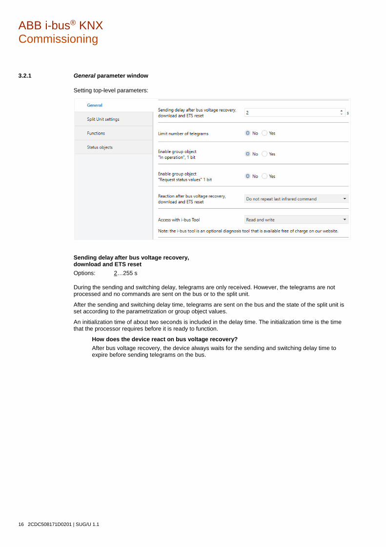
ABB i-bus® KNX Commissioning
16 2CDC508171D0201 | SUG/U 1.1
3.2.1 General parameter window
Setting top-level parameters:
Sending delay after bus voltage recovery, download and ETS reset Options: 2…255 s
During the sending and switching delay, telegrams are only received. However, the telegrams are not processed and no commands are sent on the bus or to the split unit.
After the sending and switching delay time, telegrams are sent on the bus and the state of the split unit is set according to the parametrization or group object values.
An initialization time of about two seconds is included in the delay time. The initialization time is the time that the processor requires before it is ready to function.
How does the device react on bus voltage recovery? After bus voltage recovery, the device always waits for the sending and switching delay time to expire before sending telegrams on the bus.
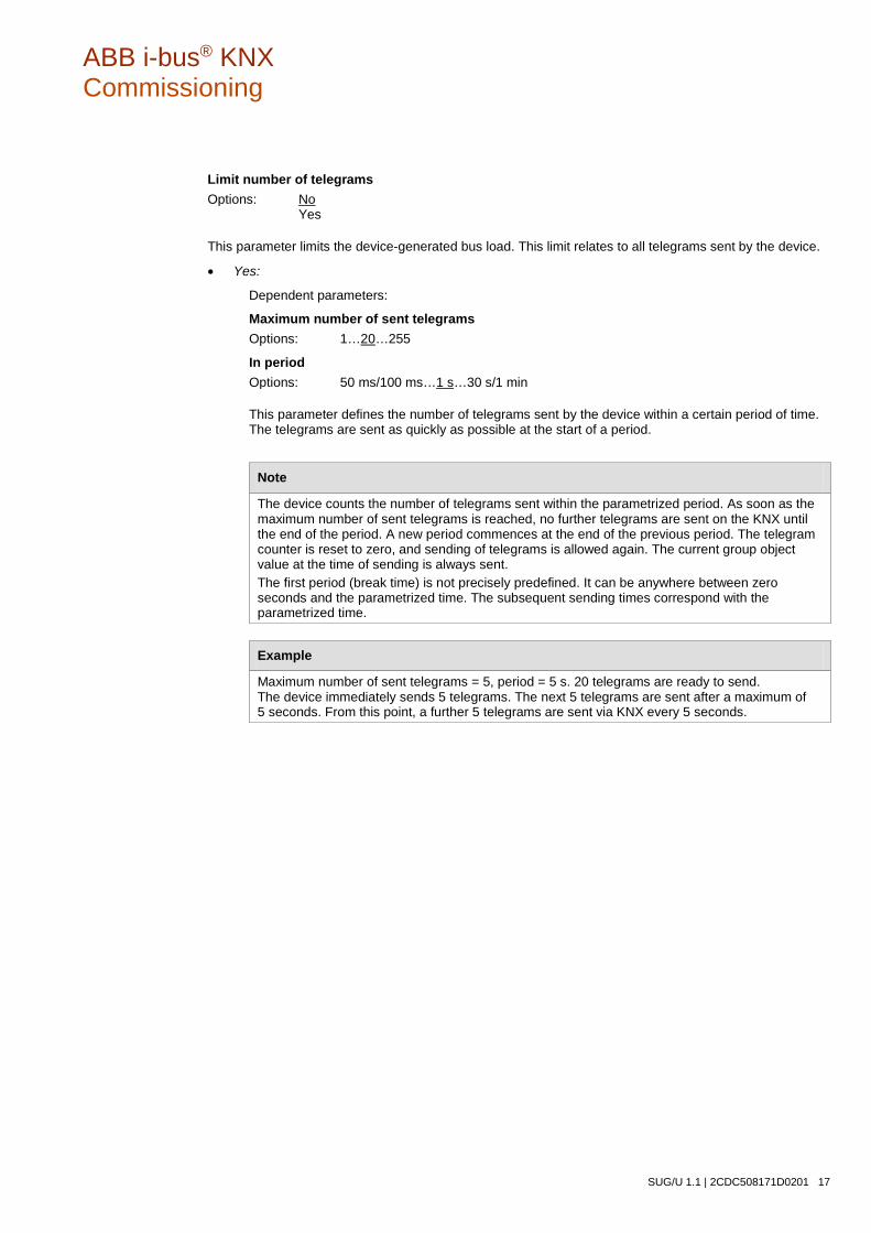
ABB i-bus® KNX Commissioning
SUG/U 1.1 | 2CDC508171D0201 17
Limit number of telegrams Options: No Yes
This parameter limits the device-generated bus load. This limit relates to all telegrams sent by the device.
• Yes:
Dependent parameters:
Maximum number of sent telegrams Options: 1…20…255
In period Options: 50 ms/100 ms…1 s…30 s/1 min
This parameter defines the number of telegrams sent by the device within a certain period of time. The telegrams are sent as quickly as possible at the start of a period.
Note
The device counts the number of telegrams sent within the parametrized period. As soon as the maximum number of sent telegrams is reached, no further telegrams are sent on the KNX until the end of the period. A new period commences at the end of the previous period. The telegram counter is reset to zero, and sending of telegrams is allowed again. The current group object value at the time of sending is always sent. The first period (break time) is not precisely predefined. It can be anywhere between zero seconds and the parametrized time. The subsequent sending times correspond with the parametrized time.
Example
Maximum number of sent telegrams = 5, period = 5 s. 20 telegrams are ready to send. The device immediately sends 5 telegrams. The next 5 telegrams are sent after a maximum of 5 seconds. From this point, a further 5 telegrams are sent via KNX every 5 seconds.

ABB i-bus® KNX Commissioning
18 2CDC508171D0201 | SUG/U 1.1
Enable group object "In operation", 1 bit Options: No Yes
• Yes: Enables the 1-bit group object In operation.
Dependent parameters:
Sending Options: Value 0 Value 1
Sending cycle time Options: 1…60…65,535 s
The time interval at which the In operation group object cyclically sends a telegram is set here.
Note
After bus voltage recovery, the group object sends its value after the set sending and switching delay time.
Enable group object "Request status values" 1 bit Options: No Yes
All status messages can be requested via this group object, provided they have been parametrized with the option After a change or request.
• Yes: Enables the 1-bit group object Request status values.
Dependent parameter:
Request with object value Options: 0 1 0 or 1
• 0: Sending status messages is requested with the value 0.
• 1: Sending status messages is requested with the value 1.
• 0 or 1: Sending status messages is requested with the values 0 or 1.

ABB i-bus® KNX Commissioning
SUG/U 1.1 | 2CDC508171D0201 19
Reaction after bus voltage recovery, download and ETS reset Options: Do not repeat last infrared command Repeat last infrared command User-defined
• Do not repeat last infrared command: The last command sent before bus voltage failure is not resent
to the split unit. If the split unit was operated with a remote control during the bus voltage failure, it is possible (until the next command via KNX) that the status of the split unit will not match the KNX status.
• Repeat last infrared command: The last command sent before bus voltage failure is resent to the split unit. This ensures that the split unit is restored to the required state in the event that the unit was operated with a remote control during bus voltage failure.
• User-defined: The reaction can be individually parametrized for each function. (On/Off, Setpoint temperature, Operation mode, Fan speed, Swing, Silent Mode). Additional parameters will appear accordingly.
Access with i-bus Tool Options: Read and write Read only request Disabled
Note
The i-bus Tool® is an optional diagnosis tool that is available free of charge on our website.
• Read and write: The i-bus® Tool has full access to the device and all functions supported by the tool can be executed.
• Read only request: The i-bus® Tool only has read access; no commands can be sent to the device.
• Disabled: The tool has no access to the device.

ABB i-bus® KNX Commissioning
20 2CDC508171D0201 | SUG/U 1.1
3.2.2 Split Unit settings parameter window
This window is used to set specific parameters for the split unit:
Manufacturer Options: Manufacturer
Remote control (type) Options: Remote control model
These parameters indicate the manufacturer of the split unit and the remote control model.
Before ETS download, the split unit manufacturer and remote control model must be selected using the "ABB SUG/U 1.1" ETS app which is available free from the KNX Online Shop. The app also displays the range of functions on the split unit and, if applicable, which ones are mapped.
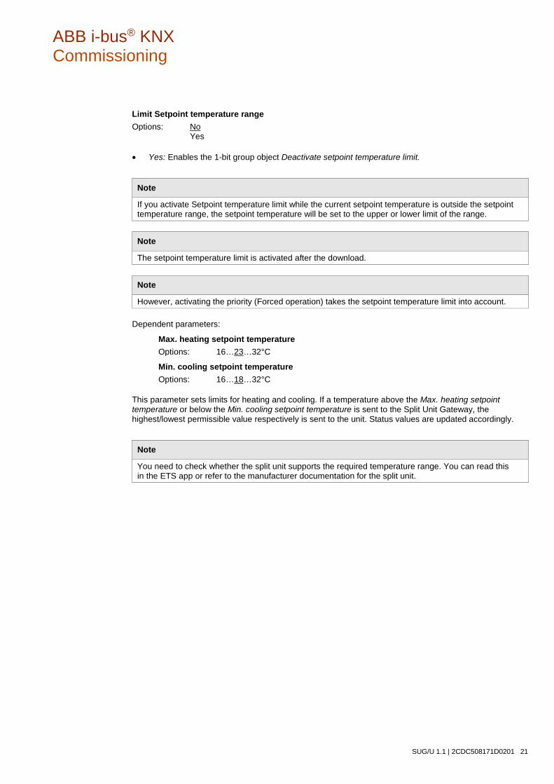
ABB i-bus® KNX Commissioning
SUG/U 1.1 | 2CDC508171D0201 21
Limit Setpoint temperature range Options: No Yes
• Yes: Enables the 1-bit group object Deactivate setpoint temperature limit.
Note
If you activate Setpoint temperature limit while the current setpoint temperature is outside the setpoint temperature range, the setpoint temperature will be set to the upper or lower limit of the range.
Note
The setpoint temperature limit is activated after the download.
Note
However, activating the priority (Forced operation) takes the setpoint temperature limit into account.
Dependent parameters:
Max. heating setpoint temperature Options: 16…23…32°C
Min. cooling setpoint temperature Options: 16…18…32°C
This parameter sets limits for heating and cooling. If a temperature above the Max. heating setpoint temperature or below the Min. cooling setpoint temperature is sent to the Split Unit Gateway, the highest/lowest permissible value respectively is sent to the unit. Status values are updated accordingly.
Note
You need to check whether the split unit supports the required temperature range. You can read this in the ETS app or refer to the manufacturer documentation for the split unit.
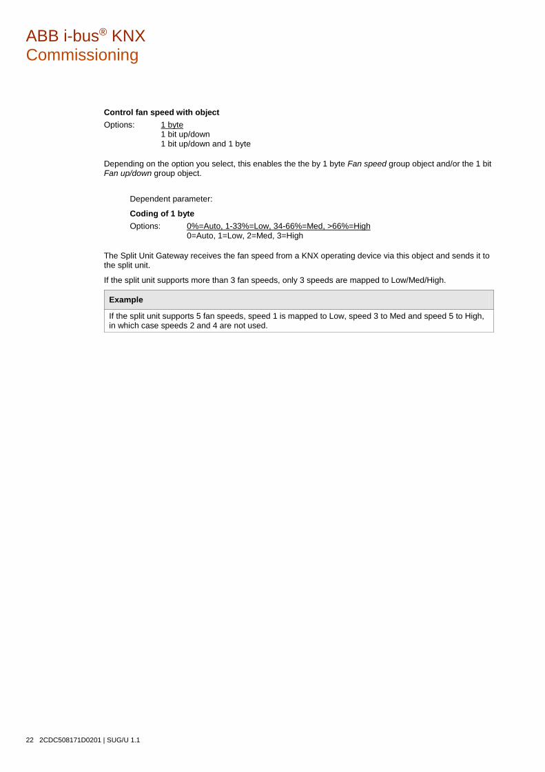
ABB i-bus® KNX Commissioning
22 2CDC508171D0201 | SUG/U 1.1
Control fan speed with object Options: 1 byte 1 bit up/down 1 bit up/down and 1 byte
Depending on the option you select, this enables the the by 1 byte Fan speed group object and/or the 1 bit Fan up/down group object.
Dependent parameter:
Coding of 1 byte Options: 0%=Auto, 1-33%=Low, 34-66%=Med, >66%=High 0=Auto, 1=Low, 2=Med, 3=High
The Split Unit Gateway receives the fan speed from a KNX operating device via this object and sends it to the split unit.
If the split unit supports more than 3 fan speeds, only 3 speeds are mapped to Low/Med/High.
Example
If the split unit supports 5 fan speeds, speed 1 is mapped to Low, speed 3 to Med and speed 5 to High, in which case speeds 2 and 4 are not used.
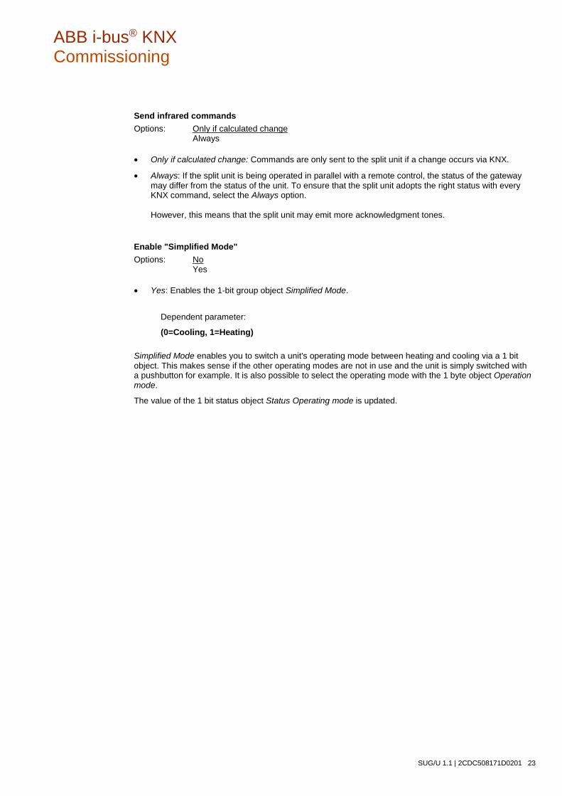
ABB i-bus® KNX Commissioning
SUG/U 1.1 | 2CDC508171D0201 23
Send infrared commands Options: Only if calculated change Always
• Only if calculated change: Commands are only sent to the split unit if a change occurs via KNX.
• Always: If the split unit is being operated in parallel with a remote control, the status of the gateway may differ from the status of the unit. To ensure that the split unit adopts the right status with every KNX command, select the Always option. However, this means that the split unit may emit more acknowledgment tones.
Enable "Simplified Mode" Options: No Yes
• Yes: Enables the 1-bit group object Simplified Mode.
Dependent parameter:
(0=Cooling, 1=Heating)
Simplified Mode enables you to switch a unit's operating mode between heating and cooling via a 1 bit object. This makes sense if the other operating modes are not in use and the unit is simply switched with a pushbutton for example. It is also possible to select the operating mode with the 1 byte object Operation mode.
The value of the 1 bit status object Status Operating mode is updated.
ABB i-bus® KNX Commissioning
24 2CDC508171D0201 | SUG/U 1.1
Enable "Silent Mode" Options: No Yes
• Yes: Enables the 1-bit group object Silent Mode.
Not all split units support Silent Mode. Where they do, it can be used to set the split unit to a low-noise operating mode, which can be useful at night for example.
Information on precisely how the split unit reacts in this mode is provided in the product manual for the unit.
Enable "Swing" (horizontal and vertical) Options: No Yes
• Yes: Enables the 1-bit group objects Horizontal Swing and Vertical Swing.
Not all split units support swing. Where they do, it can be used to start and stop horizontal and/or vertical swing.
Note
Some split unit manufacturers use the terms "horizontal" and "vertical" differently. Some are referring to the airflow direction setting, and others to the slat position. The group objects "Horizontal swing" and "Vertical swing" can be used for either of these meanings (i.e. however it is worded in the project).
ABB i-bus® KNX Commissioning
SUG/U 1.1 | 2CDC508171D0201 25
Enable "On/Off delay" function Options: No Yes
• Yes: Enables the 1-bit group object Deactivate On/Off delay.
Dependent parameter:
On/Off delay Options: 1…10…255 min
Sending a telegram with the value 0 to the On/Off object delays switching off the split unit (i.e. sending the infrared command) by the parametrized time.
Note
The switching off delay is activated after the download.

ABB i-bus® KNX Commissioning
26 2CDC508171D0201 | SUG/U 1.1
3.2.3 Functions parameter window
Function priorities are as follows:
1) Forced operation
2) Window contact
3) Presence, scenes, boost and group objects without priority
If several priorities are activated at once, the highest priority is executed.
The lower priorities are updated in the background and only executed once the higher priority is deactivated.
While a priority is active, Presence and Scene are still evaluated, but Boost and other non-priority group objects are discarded.
Timers (switching off delay, monitoring time) start immediately.
Enable "Forced operation" function Options: No Yes
• Yes: Enables the 1-bit group object Forced operation.
This enables the corresponding parameter window.

ABB i-bus® KNX Commissioning
SUG/U 1.1 | 2CDC508171D0201 27
Enable "Window contact" function Options: No Yes
• Yes: Enables the 1-bit group object Window contact.
This enables the corresponding parameter window.
Enable "Presence" function Options: No Yes
• Yes: Enables the 1-bit group object Presence.
This enables the corresponding parameter window.
Enable "Scene" function Options: No Yes
• Yes: Enables the 1-bit group object Scene.
This enables the corresponding parameter window.
Enable "Boost" function Options: No Yes
• Yes: Enables the 1-bit group object Boost.
This enables the corresponding parameter window.
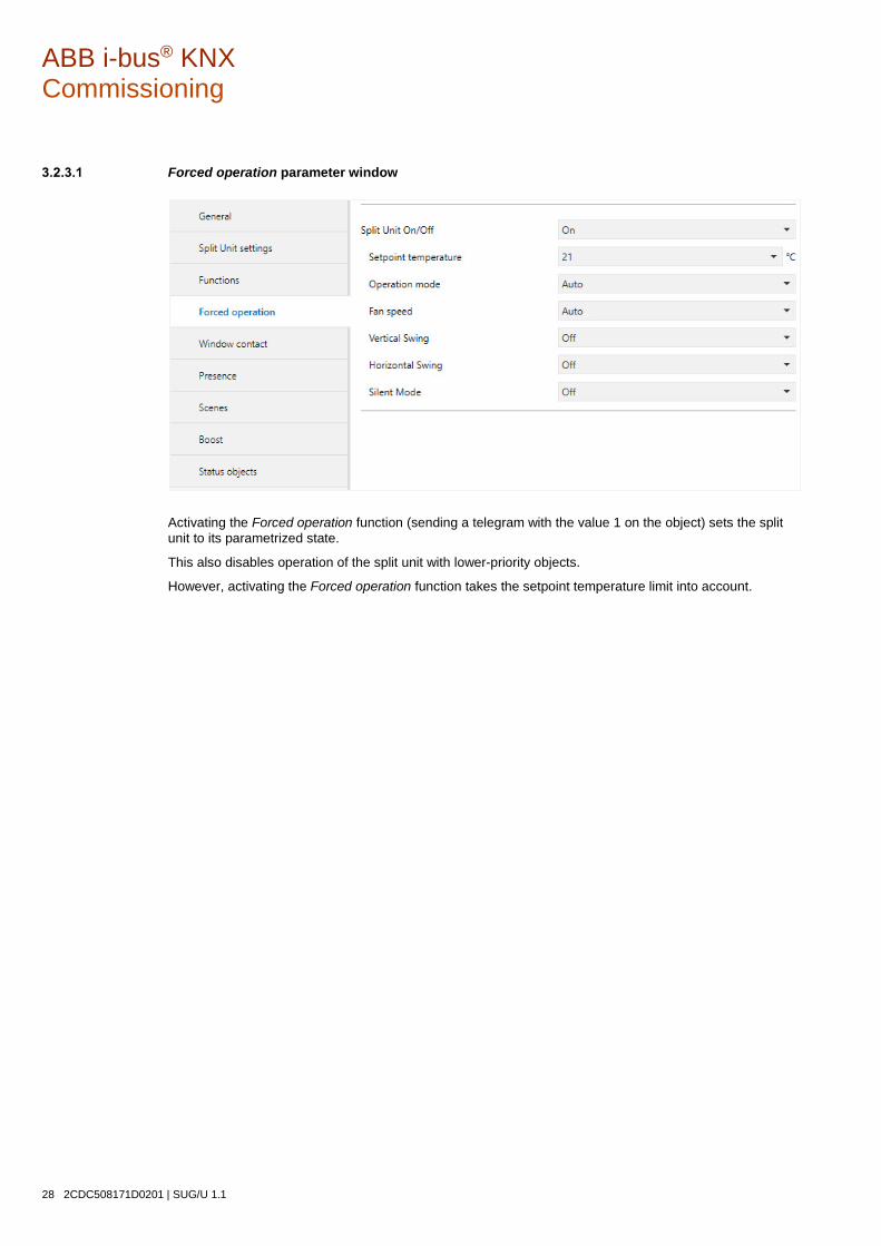
ABB i-bus® KNX Commissioning
28 2CDC508171D0201 | SUG/U 1.1
Forced operation parameter window
Activating the Forced operation function (sending a telegram with the value 1 on the object) sets the split unit to its parametrized state.
This also disables operation of the split unit with lower-priority objects.
However, activating the Forced operation function takes the setpoint temperature limit into account.

ABB i-bus® KNX Commissioning
SUG/U 1.1 | 2CDC508171D0201 29
Window contact parameter window
Activating the Window contact function (sending a telegram with the value 1 on the object) switches the split unit off.
You can also parametrize a switching off delay.
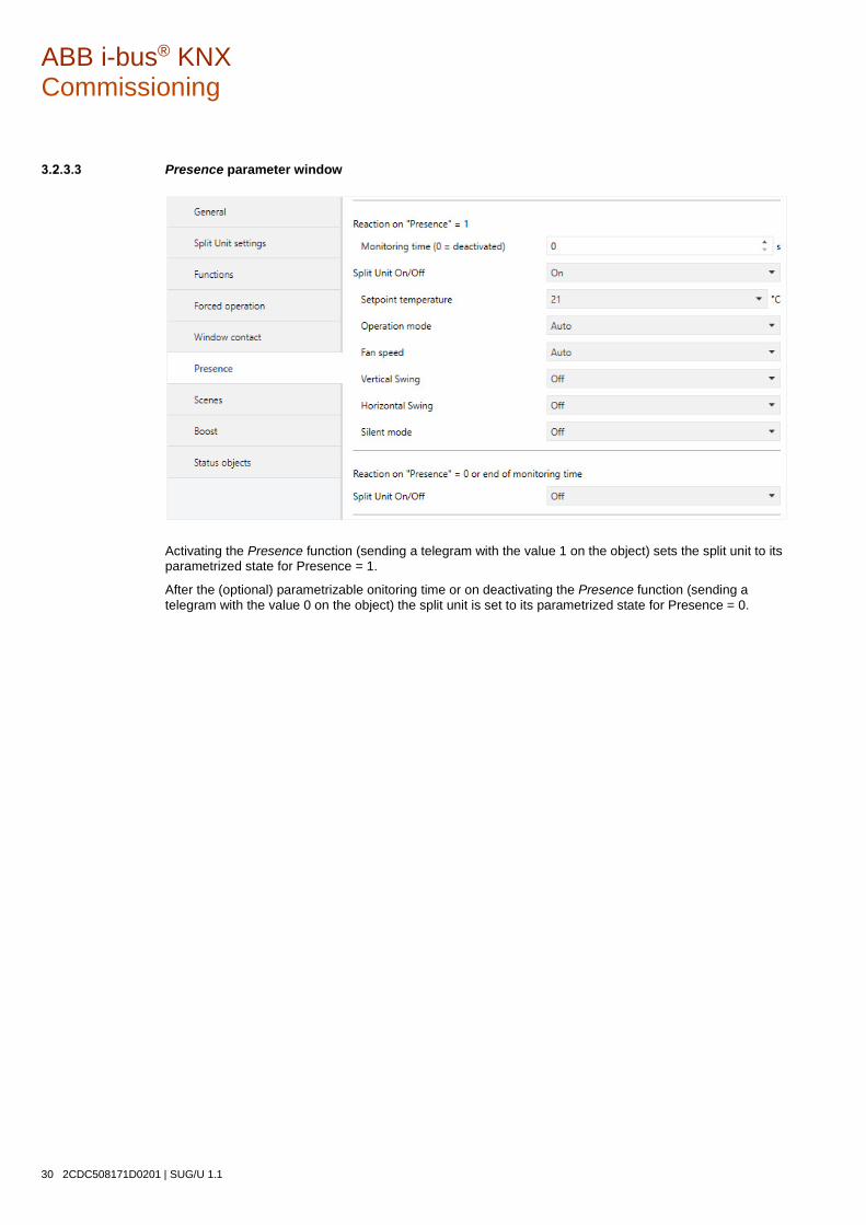
ABB i-bus® KNX Commissioning
30 2CDC508171D0201 | SUG/U 1.1
Presence parameter window
Activating the Presence function (sending a telegram with the value 1 on the object) sets the split unit to its parametrized state for Presence = 1.
After the (optional) parametrizable onitoring time or on deactivating the Presence function (sending a telegram with the value 0 on the object) the split unit is set to its parametrized state for Presence = 0.
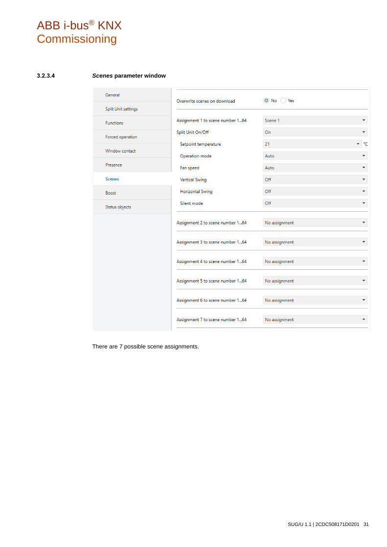
ABB i-bus® KNX Commissioning
SUG/U 1.1 | 2CDC508171D0201 31
Scenes parameter window
There are 7 possible scene assignments.
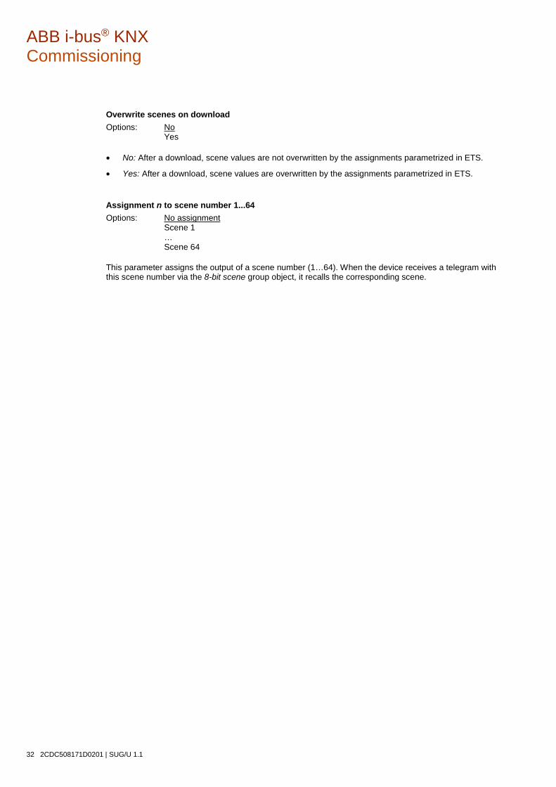
ABB i-bus® KNX Commissioning
32 2CDC508171D0201 | SUG/U 1.1
Overwrite scenes on download Options: No Yes
• No: After a download, scene values are not overwritten by the assignments parametrized in ETS.
• Yes: After a download, scene values are overwritten by the assignments parametrized in ETS.
Assignment n to scene number 1...64 Options: No assignment Scene 1 … Scene 64
This parameter assigns the output of a scene number (1…64). When the device receives a telegram with this scene number via the 8-bit scene group object, it recalls the corresponding scene.

ABB i-bus® KNX Commissioning
SUG/U 1.1 | 2CDC508171D0201 33
Boost parameter window
Boost function duration Options: 1…10…255 min
The Boost function allows you to bring a room to the required setpoint temperature very quickly.
Activating the function via the "Boost" object switches the split unit to the highest fan speed and activates swing.
After the parametrized duration, the split unit returns to its original state.

ABB i-bus® KNX Commissioning
34 2CDC508171D0201 | SUG/U 1.1
3.2.4 Status objects parameter window
Send status values Options: No (update only) On change After request After a change or request
• No (update only): The status is updated but not sent.
• On change: The status is sent when a change occurs.
• After request: The status is sent when a request occurs.
• After a change or request: The status is sent when a change or request occurs.

ABB i-bus® KNX Commissioning
SUG/U 1.1 | 2CDC508171D0201 35
Send status values after bus voltage recovery, download and ETS reset Options: No Yes
• Yes: Sends all status values to the bus after a bus voltage recovery, download or ETS reset
regardless of the parametrization of Send status values. Sending delays parametrized in the General parameter window are taken into account.
Note
Status objects can only be enabled if the corresponding function is enabled on the Functions page.

ABB i-bus® KNX Commissioning
36 2CDC508171D0201 | SUG/U 1.1
3.3 Group objects
3.3.1 Summary of group objects
No. Function Name Data Point Type (DPT) Length
Flags
C L W T R
1 In operation General 1.002 1 bit x x x
2 Request Status values General 1.017 1 bit x x
3 Fan speed Split unit 5.001
1 byte x x 5.010
4 Status Fan speed Split unit 5.001
1 byte x x x 5.010
5 Fan up/down Split unit 1.007 1 bit x x
6 Operation mode Split unit 20.105 1 byte x x
7 Status Operating mode Split unit 20.105 1 byte x x x
8 Simplified Mode Split unit 1,100 1 bit x x
9 Silent Mode Split unit 1.002 1 bit x x
10 Status Silent Mode Split unit 1.002 1 bit x x x
11 Scene Function 18.001 1 byte x x
12 On/Off Split unit 1.001 1 bit x x
13 Status On/Off Split unit 1.001 1 bit x x x
14 Deactivate On/Off delay Split unit 1.003 1 bit x x
15 Forced operation Function 1.003 1 bit x x
16 Status Forced operation Function 1.003 1 bit x x x
17 Window contact Function 1.019 1 bit x x
18 Status Window contact Function 1.019 1 bit x x x
19 Presence Function 1.018 1 bit x x
20 Status Presence Function 1.018 1 bit x x x
21 Setpoint temperature Split unit 9.001 2 byte x x
22 Status Setpoint temperature Split unit 9.001 2 byte x x x
23 Setpoint temperature up/down Split unit 1.007 1 bit x x
24 Deactivate Setpoint temperature limit Split unit 1.003 1 bit x x
25 Vertical Swing Split unit 1.001 1 bit x x
26 Status Vertical swing Split unit 1.001 1 bit x x x
27 Horizontal Swing Split unit 1.001 1 bit x x
28 Status Horizontal swing Split unit 1.001 1 bit x x x
29 Boost Function 1.001 1 bit x x
30 Status Boost Function 1.001 1 bit x x x
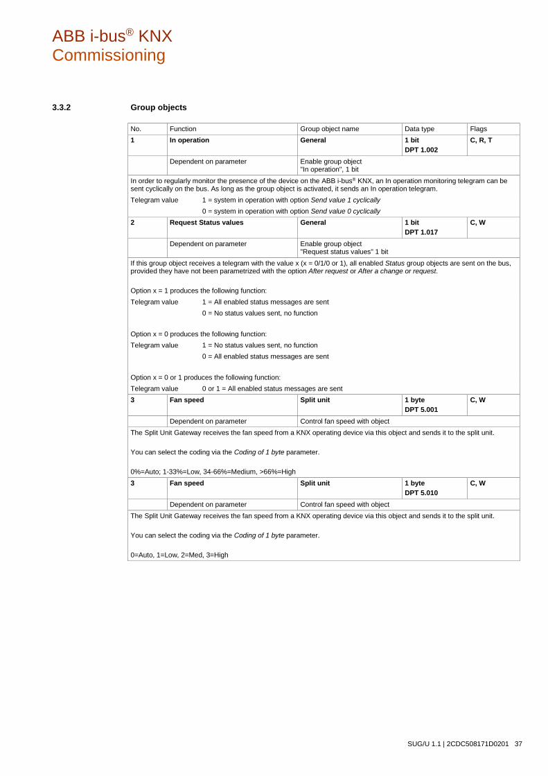
ABB i-bus® KNX Commissioning
SUG/U 1.1 | 2CDC508171D0201 37
3.3.2 Group objects
No. Function Group object name Data type Flags 1 In operation General 1 bit
DPT 1.002 C, R, T
Dependent on parameter Enable group object "In operation", 1 bit
In order to regularly monitor the presence of the device on the ABB i-bus® KNX, an In operation monitoring telegram can be sent cyclically on the bus. As long as the group object is activated, it sends an In operation telegram. Telegram value 1 = system in operation with option Send value 1 cyclically 0 = system in operation with option Send value 0 cyclically 2 Request Status values General 1 bit
DPT 1.017 C, W
Dependent on parameter Enable group object "Request status values" 1 bit
If this group object receives a telegram with the value x (x = 0/1/0 or 1), all enabled Status group objects are sent on the bus, provided they have not been parametrized with the option After request or After a change or request. Option x = 1 produces the following function: Telegram value 1 = All enabled status messages are sent 0 = No status values sent, no function
Option x = 0 produces the following function: Telegram value 1 = No status values sent, no function 0 = All enabled status messages are sent
Option x = 0 or 1 produces the following function: Telegram value 0 or 1 = All enabled status messages are sent 3 Fan speed Split unit 1 byte
DPT 5.001 C, W
Dependent on parameter Control fan speed with object The Split Unit Gateway receives the fan speed from a KNX operating device via this object and sends it to the split unit. You can select the coding via the Coding of 1 byte parameter. 0%=Auto; 1-33%=Low, 34-66%=Medium, >66%=High 3 Fan speed Split unit 1 byte
DPT 5.010 C, W
Dependent on parameter Control fan speed with object The Split Unit Gateway receives the fan speed from a KNX operating device via this object and sends it to the split unit. You can select the coding via the Coding of 1 byte parameter. 0=Auto, 1=Low, 2=Med, 3=High

ABB i-bus® KNX Commissioning
38 2CDC508171D0201 | SUG/U 1.1
No. Function Group object name Data type Flags 4 Status Fan speed Split unit 1 byte
DPT 5.001 C, R, T
Dependent on parameter Enable group object "Status Fan speed" 1 byte The fan speed status is always shown by the 1 byte object, even if Control fan speed with object parameter is set to 1 bit up/down on the Split Unit settings page. The coding of the status object is dependent on the setting in the Coding of 1 byte parameter. 0%=Auto; 33%=Low, 66%=Medium, 100%=High 4 Status Fan speed Split unit 1 byte
DPT 5.010 C, R, T
Dependent on parameter Enable group object "Status Fan speed" 1 byte The fan speed status is always shown by the 1 byte object, even if Control fan speed with object parameter is set to 1 bit up/down on the Split Unit settings page. The coding of the status object is dependent on the setting in the Coding of 1 byte parameter. 0=Auto, 1=Low, 2=Med, 3=High 5 Fan up/down Split unit 1 bit
DPT 1.007 C, W
Dependent on parameter Control fan speed with object When a telegram is received on this object, the fan speed reduces or increases by one speed. Value 1: Increases fan speed Value 0: Reduces fan speed Available fan speeds are: Automatic, Low, Medium, High If the fan reaches High, a further telegram with the value 1 has no effect. If the fan is set to Automatic, a further telegram with the value 0 has no effect. 6 Operation mode Split unit 1 byte
DPT 20.105 C, W
Dependent on parameter Always visible This object sets the operating mode for the split unit. The operating modes set on receipt of a corresponding value are as follows: 0=Auto 1=Heating 3=Cooling 9=Ventilation 14=Drying All other values are discarded.

ABB i-bus® KNX Commissioning
SUG/U 1.1 | 2CDC508171D0201 39
No. Function Group object name Data type Flags 7 Status Operating mode Split unit 1 byte
DPT 20.105 C, R, T
Dependent on parameter Always visible This object indicates the operating mode status for the split unit. 0=Auto 1=Heating 3=Cooling 9=Ventilation 14=Drying 8 Simplified Mode Split unit 1 bit
DPT 1.100 C, W
Dependent on parameter Enable "Simplified Mode" This object switches between heating and cooling for basic applications. 1=Heating 0=Cooling It is possible to operate the unit in parallel using object 6. The operating mode status (object 7) is updated. 9 Silent Mode Split unit 1 bit
DPT 1.002 C, W
Dependent on parameter Enable "Silent Mode" This object activates Silent Mode, provided the split unit supports it. 1=Activate Silent Mode 0=Deactivate Silent Mode 10 Status Silent Mode Split unit 1 bit
DPT 1.002 C, R, T
Dependent on parameter Enable "Silent Mode" and Enable group object "Status Silent Mode" 1-bit
This object indicates the status of Silent Mode. 1=Silent Mode activated 0=Silent Mode deactivated 11 Scene General 1 byte
DPT 18.001 C, W
Dependent on parameter Enable "Scene" function Using this 8-bit group object, a Scene telegram can be sent using a coded telegram. The telegram contains the number of the scene concerned as well as the information on whether the scene is to be recalled or stored. The coding for this object is provided in Appendix 1.
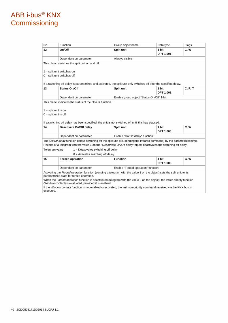
ABB i-bus® KNX Commissioning
40 2CDC508171D0201 | SUG/U 1.1
No. Function Group object name Data type Flags 12 On/Off Split unit 1 bit
DPT 1.001 C, W
Dependent on parameter Always visible This object switches the split unit on and off. 1 = split unit switches on 0 = split unit switches off If a switching off delay is parametrized and activated, the split unit only switches off after the specified delay. 13 Status On/Off Split unit 1 bit
DPT 1.001 C, R, T
Dependent on parameter Enable group object "Status On/Off" 1-bit This object indicates the status of the On/Off function. 1 = split unit is on 0 = split unit is off If a switching off delay has been specified, the unit is not switched off until this has elapsed. 14 Deactivate On/Off delay Split unit 1 bit
DPT 1.003 C, W
Dependent on parameter Enable "On/Off delay" function The On/Off delay function delays switching off the split unit (i.e. sending the infrared command) by the parametrized time. Receipt of a telegram with the value 1 on the "Deactivate On/Off delay" object deactivates the switching off delay. Telegram value 1 = Deactivates switching off delay 0 = Activates switching off delay 15 Forced operation Function 1 bit
DPT 1.003 C, W
Dependent on parameter Enable "Forced operation" function Activating the Forced operation function (sending a telegram with the value 1 on the object) sets the split unit to its parametrized state for forced operation. When the Forced operation function is deactivated (telegram with the value 0 on the object), the lower-priority function (Window contact) is evaluated, provided it is enabled. If the Window contact function is not enabled or activated, the last non-priority command received via the KNX bus is executed.
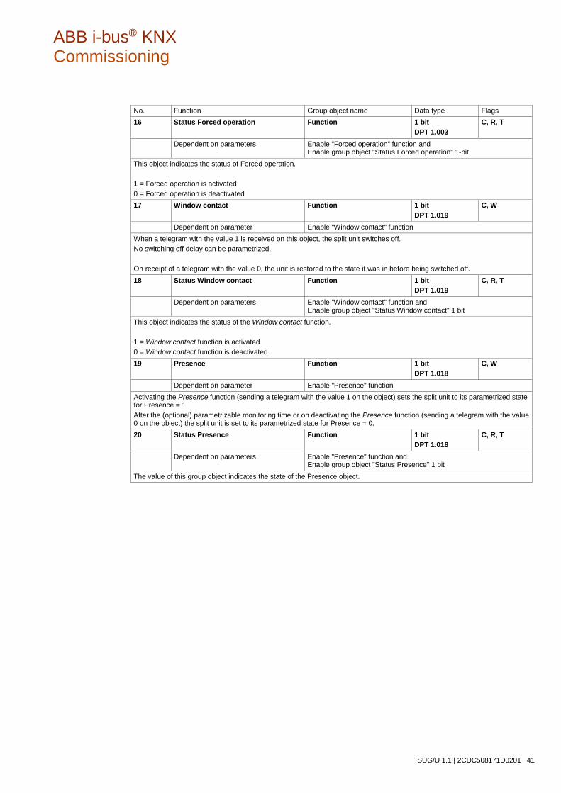
ABB i-bus® KNX Commissioning
SUG/U 1.1 | 2CDC508171D0201 41
No. Function Group object name Data type Flags 16 Status Forced operation Function 1 bit
DPT 1.003 C, R, T
Dependent on parameters Enable "Forced operation" function and Enable group object "Status Forced operation" 1-bit
This object indicates the status of Forced operation. 1 = Forced operation is activated 0 = Forced operation is deactivated 17 Window contact Function 1 bit
DPT 1.019 C, W
Dependent on parameter Enable "Window contact" function When a telegram with the value 1 is received on this object, the split unit switches off. No switching off delay can be parametrized. On receipt of a telegram with the value 0, the unit is restored to the state it was in before being switched off. 18 Status Window contact Function 1 bit
DPT 1.019 C, R, T
Dependent on parameters Enable "Window contact" function and Enable group object "Status Window contact" 1 bit
This object indicates the status of the Window contact function. 1 = Window contact function is activated 0 = Window contact function is deactivated 19 Presence Function 1 bit
DPT 1.018 C, W
Dependent on parameter Enable "Presence" function Activating the Presence function (sending a telegram with the value 1 on the object) sets the split unit to its parametrized state for Presence = 1. After the (optional) parametrizable monitoring time or on deactivating the Presence function (sending a telegram with the value 0 on the object) the split unit is set to its parametrized state for Presence = 0. 20 Status Presence Function 1 bit
DPT 1.018 C, R, T
Dependent on parameters Enable "Presence" function and Enable group object "Status Presence" 1 bit
The value of this group object indicates the state of the Presence object.

ABB i-bus® KNX Commissioning
42 2CDC508171D0201 | SUG/U 1.1
No. Function Group object name Data type Flags 21 Setpoint temperature Split unit 2 byte
DPT 9.001 C, W
Dependent on parameters Always visible The Split Unit Gateway receives the setpoint value via this group object. If when the Setpoint temperature limit is parametrized and activated the gateway receives setpoint values outside the parametrized range, it sets the setpoint temperature to the upper or lower limit of the range. If you activate Setpoint temperature limit while the current setpoint temperature is outside the setpoint temperature range, the setpoint temperature will be set to the upper or lower limit of the range. 22 Status Setpoint temperature Split unit 2 byte
DPT 9.001 C, R, T
Dependent on parameter Enable group object "Status setpoint temperature" 2 bytes This object indicates the current setpoint value. 23 Setpoint temperature up/down Split unit 1 bit
DPT 1.007 C, W
Dependent on parameter Always visible This object increases or reduces the setpoint temperature by intervals of 1 kelvin. 1 = Setpoint temperature increases 0 = Setpoint temperature decreases If the temperature reaches the upper or lower setpoint temperature limit, further telegrams have no effect. 24 Deactivate Setpoint temperature limit Split unit 1 bit
DPT 1.003 C, W
Dependent on parameter Limit Setpoint temperature range This object activates/deactivates the setpoint temperature limit 1 = Setpoint temperature limit deactivated 0 = Setpoint temperature limit activated If you activate Setpoint temperature limit while the current setpoint temperature is outside the setpoint temperature range, the setpoint temperature will be set to the upper or lower limit of the range. The setpoint temperature limit is activated after download. However, activating the Forced operation priority takes the setpoint temperature limit into account.

ABB i-bus® KNX Commissioning
SUG/U 1.1 | 2CDC508171D0201 43
No. Function Group object name Data type Flags 25 Vertical Swing Split unit 1 bit
DPT 1.001 C, W
Dependent on parameter Enable "Swing" See Enable "Swing" (horizontal and vertical), p. 24
This object starts and stops horizontal and/or vertical swing. 1 = vertical swing starts 0 = vertical swing stops
Note
On certain split units, the slats move to a specific position when swing is stopped.
26 Status Vertical swing Split unit 1 bit
DPT 1.001 C, R, T
Dependent on parameters Enable "Swing" and Enable group object "Status Swing" 1 bit See Enable "Swing" (horizontal and vertical), p. 24
This object indicates the status of vertical swing. 1 = vertical swing started 0 = vertical swing stopped 27 Horizontal Swing Split unit 1 bit
DPT 1.001 C, W
Dependent on parameter Enable "Swing" See Enable "Swing" (horizontal and vertical), p. 24
This object starts and stops horizontal swing. 1 = starts horizontal swing 0 = stops horizontal swing
Note
On certain split units, the slats move to a specific position when swing is stopped.

ABB i-bus® KNX Commissioning
44 2CDC508171D0201 | SUG/U 1.1
No. Function Group object name Data type Flags 28 Status Horizontal swing Split unit 1 bit
DPT 1.003 C, R, T
Dependent on parameters Enable "Swing" and Enable group object "Status Swing" 1 bit See Enable "Swing" (horizontal and vertical), p. 24
This object indicates the status of horizontal swing. 1 = horizontal swing started 0 = horizontal swing stopped 29 Boost Function 1 bit
DPT 1.001 C, W
Dependent on parameter Enable "Boost" function Receipt of a telegram with the value 1 on this object activates the Boost function. The split unit switches to the highest fan speed and swing is activated. After the parametrized duration the split unit returns to its original state. 30 Status Boost Function 1 bit
DPT 1.001 C, R, T
Dependent on parameters Enable "Boost" function and Enable group object "Status Boost" 1 bit
This object indicates the status of the Boost function. 1 = Boost function is activated 0 = Boost function is deactivated

ABB i-bus® KNX Commissioning
SUG/U 1.1 | 2CDC508171D0201 45
3.4 Special operating states
3.4.1 Reaction on bus voltage failure
In the event of a bus voltage failure, the Split Unit Gateway sends no infrared commands.
3.4.2 Reaction on bus voltage recovery
Input objects are initialized at 0.
Status objects are sent according to the "Send status values after bus voltage recovery, download and ETS reset" parameter on the "Status objects" page. Sending delays parametrized on the "General" parameter page are taken into account.
IR commands to the split unit are sent according to the "Reaction on bus voltage recovery, download and ETS reset" parameter on the "General" page.
Priorities are not active.
Timers (On/Off delay, window switching off delay, presence monitoring time, boost function duration) are reset and the action set to occur when the timer has finished is executed.
3.4.3 Reaction on ETS download
Input objects are initialized at 0. This excludes the input objects On/Off delay, Temperature limit, Forced operation, Window contact, Presence and Boost. These are initialized according to the operating state before the download.
Status objects are sent according to the "Send status values after bus voltage recovery, download and ETS reset" parameter on the "Status objects" page. Sending delays parametrized on the "General" parameter page are taken into account.
IR commands to the split unit are sent according to the "Reaction on bus voltage recovery, download and ETS reset" parameter on the "General" page.
Priorities remain unchanged (for more information, see: chapter 3.2.3, page 26).
Timers (On/Off delay, window switching off delay, presence monitoring time, boost function duration) restart if they were active before the download.
ABB i-bus® KNX Commissioning
46 2CDC508171D0201 | SUG/U 1.1
3.4.4 Reaction on ETS reset
Input objects are initialized at 0. Exception: the object "Setpoint temperature" is initialized at 18 °C. The value can differ from this if setpoint temperature limitation is active.
Status objects are sent according to the "Send status values after bus voltage recovery, download and ETS reset" parameter on the "Status objects" page. Sending delays parametrized on the "General" parameter page are taken into account.
IR commands to the split unit are always sent with the initialized values, irrespective of the parameter "Reaction on bus voltage recovery, download and ETS reset".
Priorities are not active.
Timers (On/Off delay, window switching off delay, presence monitoring time, boost function duration) are reset and the action set to occur when the timer has finished is executed.
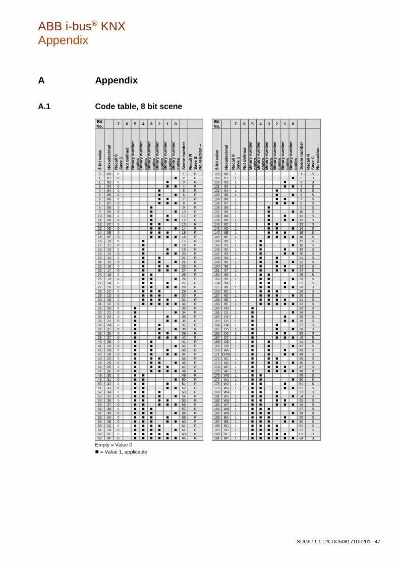
ABB i-bus® KNX Appendix
SUG/U 1.1 | 2CDC508171D0201 47
A Appendix
A.1 Code table, 8 bit scene Bit No. 7 6 5 4 3 2 1 0 Bit
No. 7 6 5 4 3 2 1 0
8-bi
t val
ue
Hex
adec
imal
R
ecal
l 0
Save
1
Not
def
ined
B
inar
y nu
mbe
r co
des
Bin
ary
num
ber
code
s B
inar
y nu
mbe
r co
des
Bin
ary
num
ber
code
s B
inar
y nu
mbe
r co
des
Bin
ary
num
ber
code
s Sc
ene
num
ber
Rec
all R
Sa
ve S
N
o re
actio
n –
8-bi
t val
ue
Hex
adec
imal
R
ecal
l 0
Save
1
Not
def
ined
B
inar
y nu
mbe
r co
des
Bin
ary
num
ber
code
s B
inar
y nu
mbe
r co
des
Bin
ary
num
ber
code
s B
inar
y nu
mbe
r co
des
Bin
ary
num
ber
code
s Sc
ene
num
ber
Rec
all R
Sa
ve S
N
o re
actio
n –
0 00 0 1 R 128 80 1 1 S 1 01 0 2 R 129 81 1 2 S 2 02 0 3 R 130 82 1 3 S 3 03 0 4 R 131 83 1 4 S 4 04 0 5 R 132 84 1 5 S 5 05 0 6 R 133 85 1 6 S 6 06 0 7 R 134 86 1 7 S 7 07 0 8 R 135 87 1 8 S 8 08 0 9 R 136 88 1 9 S 9 09 0 10 R 137 89 1 10 S 10 0A 0 11 R 138 8A 1 11 S 11 0B 0 12 R 139 8B 1 12 S 12 0C 0 13 R 140 8C 1 13 S 13 0D 0 14 R 141 8D 1 14 S 14 0E 0 15 R 142 8E 1 15 S 15 0F 0 16 R 143 8F 1 16 S 16 10 0 17 R 144 90 1 17 S 17 11 0 18 R 145 91 1 18 S 18 12 0 19 R 146 92 1 19 S 19 13 0 20 R 147 93 1 20 S 20 14 0 21 R 148 94 1 21 S 21 15 0 22 R 149 95 1 22 S 22 16 0 23 R 150 96 1 23 S 23 17 0 24 R 151 97 1 24 S 24 18 0 25 R 152 98 1 25 S 25 19 0 26 R 153 99 1 26 S 26 1A 0 27 R 154 9A 1 27 S 27 1B 0 28 R 155 9B 1 28 S 28 1C 0 29 R 156 9C 1 29 S 29 1D 0 30 R 157 9D 1 30 S 30 1E 0 31 R 158 9E 1 31 S 31 1F 0 32 R 159 9F 1 32 S 32 20 0 33 R 160 O0 1 33 S 33 21 0 34 R 161 O1 1 34 S 34 22 0 35 R 162 O2 1 35 S 35 23 0 36 R 163 O3 1 36 S 36 24 0 37 R 164 O4 1 37 S 37 25 0 38 R 165 O5 1 38 S 38 26 0 39 R 166 O6 1 39 S 39 27 0 40 R 167 O7 1 40 S 40 28 0 41 R 168 O8 1 41 S 41 29 0 42 R 169 O9 1 42 S 42 2A 0 43 R 170 AA 1 43 S 43 2B 0 44 R 171 DOW
1 44 S
44 2C 0 45 R 172 AC 1 45 S 45 2D 0 46 R 173 AD 1 46 S 46 2E 0 47 R 174 AE 1 47 S 47 2F 0 48 R 175 AF 1 48 S 48 30 0 49 R 176 W0 1 49 S 49 31 0 50 R 177 W1 1 50 S 50 32 0 51 R 178 W2 1 51 S 51 33 0 52 R 179 W3 1 52 S 52 34 0 53 R 180 W4 1 53 S 53 35 0 54 R 181 W5 1 54 S 54 36 0 55 R 182 W6 1 55 S 55 37 0 56 R 183 W7 1 56 S 56 38 0 57 R 184 W8 1 57 S 57 39 0 58 R 185 W9 1 58 S 58 3A 0 59 R 186 BA 1 59 S 59 3B 0 60 R 187 BB 1 60 S 60 3C 0 61 R 188 BC 1 61 S 61 3D 0 62 R 189 BD 1 62 S 62 3E 0 63 R 190 BE 1 63 S 63 3F 0 64 R 191 BF 1 64 S
Empty = Value 0 = Value 1, applicable
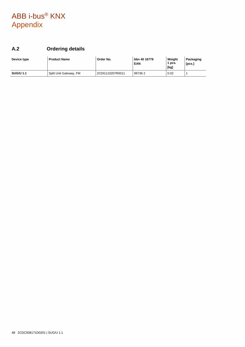
ABB i-bus® KNX Appendix
48 2CDC508171D0201 | SUG/U 1.1
A.2 Ordering details
Device type Product Name Order No. bbn 40 16779 EAN
Weight 1 pcs. [kg]
Packaging [pcs.]
SUG/U 1.1 Split Unit Gateway, FM 2CDG110207R0011 99736 2 0.02 1
ABB i-bus® KNX Appendix
SUG/U 1.1 | 2CDC508171D0201 49
A.3 Open source components
--COPYRIGHT--, BSD
Copyright (c) 2011, Texas Instruments Incorporated
All rights reserved.
Redistribution and use in source and binary forms, with or without modification, are permitted provided that the following conditions are met:
Redistributions of source code must retain the above copyright notice, this list of conditions and the following disclaimer.
Redistributions in binary form must reproduce the above copyright notice, this list of conditions and the following disclaimer in the documentation and/or other materials provided with the distribution.
Neither the name of Texas Instruments Incorporated nor the names of its contributors may be used to endorse or promote products derived from this software without specific prior written permission.
THIS SOFTWARE IS PROVIDED BY THE COPYRIGHT HOLDERS AND CONTRIBUTORS "AS IS"
AND ANY EXPRESS OR IMPLIED WARRANTIES, INCLUDING, BUT NOT LIMITED TO,
THE IMPLIED WARRANTIES OF MERCHANTABILITY AND FITNESS FOR A PARTICULAR
PURPOSE ARE DISCLAIMED. IN NO EVENT SHALL THE COPYRIGHT OWNER OR
CONTRIBUTORS BE LIABLE FOR ANY DIRECT, INDIRECT, INCIDENTAL, SPECIAL,
EXEMPLARY, OR CONSEQUENTIAL DAMAGES (INCLUDING, BUT NOT LIMITED TO,
PROCUREMENT OF SUBSTITUTE GOODS OR SERVICES; LOSS OF USE, DATA, OR PROFITS;
OR BUSINESS INTERRUPTION) HOWEVER CAUSED AND ON ANY THEORY OF LIABILITY,
WHETHER IN CONTRACT, STRICT LIABILITY, OR TORT (INCLUDING NEGLIGENCE OR
OTHERWISE) ARISING IN ANY WAY OUT OF THE USE OF THIS SOFTWARE,
EVEN IF ADVISED OF THE POSSIBILITY OF SUCH DAMAGE.

ABB i-bus® KNX Appendix
50 2CDC508171D0201 | SUG/U 1.1
A.4 Notes

ABB i-bus® KNX Appendix
SUG/U 1.1 | 2CDC508171D0201 51
Notes
ABB i-bus® KNX Appendix
52 2CDC508171D0201 | SUG/U 1.1
Notes

— ABB STOTZ-KONTAKT GmbH Eppelheimer Straße 82 69123 Heidelberg, Germany Telefon: +49 (0)6221 701 607 Telefax: +49 (0)6221 701 724 E-Mail: [email protected] Further Information and Local Contacts: www.abb.com/knx
— © Copyright 2017 ABB. We reserve the right to make technical changes or modify the contents of this document without prior notice. With regard to purchase or-ders, the agreed particulars shall prevail. ABB AG does not accept any responsibility whatsoever for potential errors or pos-sible lack of information in this document. We reserve all rights in this document and in the subject matter and illustrations con-tained therein. Any reproduction, disclosure to third par-ties or utilization of this contents - in whole or in parts - is forbidden without prior written consent of ABB AG.
Ord
er N
umb
er 2
CD
C50
8171
D0
201
(10
.20
17)