training document for simit sce - home - english...
TRANSCRIPT

Industry Sector Industrial Solutions Division
Training Document for SIMIT SCE
MODULE G2
'Startup’ System Simulation with SIMIT SCE V7
Training Document for SIMIT SCE Page 1 ofn 39 Module G2 Status: 01/2010 'Startup’ System Simulation with SIMIT SCE V7

Industry Sector Industrial Solutions Division
Status December 2009
Trademark
SIMIT is a trademark of Siemens AG.
The other names in this document may be trademarks whose use by third parties for their purposes may infringe on the rights of the proprietors.
Copyright © Siemens AG 2011 All rights reserved
Unless permission has been expressly granted by Siemens, passing on this document or copying it, or using and sharing its content is not allowed. Offenders will be held liable. All rights reserved, in the event a patent is granted, or a utility model or design is registered Siemens AG Industry Sector Industry Solutions Division
Liability Exclusion
We have checked the contents of this document regarding agreement with the hardware and software described. However, deviations can not be ruled out. For that reason, we are not guaranteeing complete agreement. The contents of this document are checked periodically and required corrections are included in subsequent versions. We appreciate suggestions for improvement.
© Siemens AG 2011
Subject to technical changes.
This document was prepared by Siemens Industry/Industry Solutions Division for training purposes. We would like to thank the Michael Dziallas Engineering corporation for their support during the preparation of this document.
Training Document for SIMIT SCE Page 2 ofn 39 Module G2 Status: 01/2010 'Startup’ System Simulation with SIMIT SCE V7

Industry Sector Industrial Solutions Division
Table of Contents
1. PREFACE.....................................................................................................................................................5
2. SPECIAL CONSIDERATIONS REGARDING THE SIMIT SCE..................................................................7
2.1 Scope of SIMIT SCE................................................................................................................................7 2.2 Limitations of SIMIT SCE.........................................................................................................................7
3. INSTALLING THE SOFTWARE ..................................................................................................................8
3.1 Prerequisites ............................................................................................................................................8 3,2 Installing the SIMIT SCE Software...........................................................................................................8 3.3 De-Installing the SIMIT SCE Software.....................................................................................................8 3.4 Installing the Software SIMIT4Students...................................................................................................8 3.5 De-Installing the Software SIMIT4Students.............................................................................................8
4. INTRODUCTION TO SIMIT SCE................................................................................................................9
4.1 Signal Input ...................................................................................................................................................9 4.2 The SIMIT SCE Interface........................................................................................................................11 4.3 Simulation Projects in SIMIT SCE .........................................................................................................12 4.5 Performing the Simulation.......................................................................................................................14
5. APPLICATION EXAMPLE "PRESS“ .......................................................................................................15
5.1 The Automation Task..............................................................................................................................15 5.2 Press Control ..........................................................................................................................................15 5.3 The Simulation ........................................................................................................................................16 5.3.6 Graphics and Animation ......................................................................................................................30
6. PROJECT MANAGEMENT ......................................................................................................................36
6.1 Archived Projects ....................................................................................................................................36 6.2 SIMIT4Students ......................................................................................................................................37
Training Document for SIMIT SCE Page 3 ofn 39 Module G2 Status: 01/2010 'Startup’ System Simulation with SIMIT SCE V7

Industry Sector Industrial Solutions Division
Training Document for SIMIT SCE Page 4 ofn 39 Module G2 Status: 01/2010 'Startup’ System Simulation with SIMIT SCE V7
The following symbols serve as a guide through Module G2: Information General Principles
This symbol is used when general principles about the respective topic are dealt with beforehand.
Installation Programming Configuration for the sample task
This symbol is used to implement the sample task.
Notes

Industry Sector Industrial Solutions Division 1. PREFACE
Regarding its content, Module G2 'SIMIT SCE V7’ part of the instruction unit “System Simulation with SIMIT SCE“ and is designed as a fast entry point for system simulation. Fundamentals of
STEP7 Programming 2 to 3 days Modules A
Industrial Fieldbus Systems 2 to 3 days Modules D
Additional Functions of STEP7 Programming 2 to 3 days Modules B
Process Visualization 2 to 3 days Modules F
Programming Languages 2 to 3 days Modules C
IT Communication with SIMATIC S7 2 to 3 days Modules E
System Simulation with SIMIT SCE 1 to 2 days Modules G
Frequency Converter at SIMATIC S7 2 to 3 days Modules H
Objective In Module G2, the reader learns how to handle the software tool SIMIT SCE V7. Module G2 provides the fundamentals and demonstrates how projects are handled and generated, based on detailed examples. Prerequisites To successfully work through Module G2, the following knowledge is assumed: • Knowledge in handling Windows • Fundamentals of PLC programming with STEP7 (for example, Module A3 – 'Startup’
PLC Programming with STEP 7)
Training Document for SIMIT SCE Page 5 ofn 39 Module G2 Status: 01/2010 'Startup’ System Simulation with SIMIT SCE V7

Industry Sector Industrial Solutions Division
Training Document for SIMIT SCE Page 6 ofn 39 Module G2 Status: 01/2010 'Startup’ System Simulation with SIMIT SCE V7
Hardware and software required 1 PC, operating system Windows XP Professional starting with SP3/Vista 32 Bit Ultimate and Business with 600MHz and 512RAM and USB connection for the dongle 2 Software SIMIT 7.0 3 Software STEP7 V 5.4 4 Software S7 PLCSIM V5.x 5 MPI for the PC (for example, PC Adapter USB) 6 PLC SIMATIC S7-300 with at least one digital input and output module. The inputs have to be brought out to a panel. Sample configuration: - Power supply: PS 307 2A - CPU: CPU 314 - Digital inputs: DI 16x 24V DC - Digital outputs: DO 16x 24V DC/0.5 A - Analog inputs/outputs: AI4/AQ2
1 PC
2 SIMIT SCE V7
6 S7-300
5 PC Adapter USB
4 S7 PLCSIM
3 STEP 7

Industry Sector Industrial Solutions Division
2. Special Considerations regarding the SIMIT SCE With the SIMIT SCE, Siemens offers a solution specifically designed to train automation technicians for the virtual startup of SIMATIC user software. By simulating technical devices or systems, your students are able to test a PLC program under realistic conditions. In this manner, the proposed task can be grasped more quickly, the student can concentrate on generating the PLC program and test it any time on the simulator. Through the appealing representation of the controlled devices and systems in the simulation, he is more highly motivated to find a correct automation-engineering solution. The SIMIT SCE campus license permits storing a simulation project as "executable simulation“. Although your students are able to start such a simulation and use it for testing, they can not change it. A precondition is that on the student’s computer the software SIMIT4Students is installed. In this manual, explanations are provided for the SIMIT SCE that make it possible to use already available simulations in class. In addition, the manual describes how to create and use your own simulations with the SIMIT SCE. In Chapter 2, the special considerations regarding the SIMIT SCE are explained and the limitations are described in comparison to SIMIT software used in industrial automation projects. Chapter 3 contains the installation instructions for the SIMIT SCE. Chapter 4 shows the handling and the general configuration of the SIMIT SCE. Chapter 5 contains, as an example, the complete step by step description of how the simulation of a simple press has to be set up. The concluding Chapter 6 describes the handling of SIMIT SCE projects and in particular how to pass on simulations to your students.
2.1 Scope of the SIMIT SCE
SIMIT SCE includes the following modules: SIMIT BASIC contains, as the basic system, project management, the graphic user interface, and a basic library consisting of components and controls.
SIMIT DGE is the SIMIT graphics editor for designing user defined diagrams
SIMIT MCE The macro component editor is used to generate macro components from standard components.
SIMIT PLCSIM The interface establishes the connection for the signal exchange of the simulation to an emulated controller in PLCSIM.
SIMIT PRODAVE The interface establishes the connection for the signal exchange to a SIMATIC controller S7-300 or S7-400.
It is possible to generate executable simulations that may be passed on to students of your own training center. SIMIT SCE is a permanently defined configuration of SIMIT and can not be expanded with additional modules.
2.2 Limitations of SIMIT SCE
SIMIT SCE has the following limitations: As interfaces, only the above mentioned PLCSIM and PRODAVE interface are available. The address area is limited to the following specified values:
o 32 binary inputs in the address area I0.0 to I3.7
o 8 analog inputs in the address area IW64 to IW78
o 32 binary outputs in the address area Q0.0 to Q3.7
o 8 analog outputs in the address area QW64 to QW78
The number of components and controls that can be used in a simulation is limited to 250.
Training Document for SIMIT SCE Page 7 ofn 39 Module G2 Status: 01/2010 'Startup’ System Simulation with SIMIT SCE V7

Industry Sector Industrial Solutions Division
3. Installing the Software Before you are able to use the SIMIT SCE, the SIMIT SCE software has to be installed on your computer. Please note that you have to be signed on as administrator on your computer to install the software.
3.1 Prerequisites
Your computer has to meet the following minimum requirements: Hardware • Standard PC • CD drive
• Free USB slot (please do not use USB extensions or hubs)
Software
SIMIT can be installed on the following Windows operating systems: • XP Professional SP3
• Vista Professional
• Vista Ultimate
3.2 Installing the SIMIT SCE Software
To install SIMIT SCE, please start the program Setup.exe that is provided in the folder SIMIT on the installation CD. If the required .NET framework is not available on your computer, the .NET framework Version 3.5 SP1 is installed first. You do not need Internet access to install SIMIT SCE. Then, the installation of SIMIT SCE is continued. If installation does not continue automatically, restart the setup program. During the SIMIT SCE installation, please follow the dialogs in the installation program.
3.3 De-Installing the SIMIT SCE Software
You can de-install the SIMIT SCE any time, of course. To this end, call the menu option Programs | SIMIT 7 | Deinstallation in the Windows start menu, or de-install SIMIT SCE using the system settings (Settings | System Control | Software). During de-installation, all files and registry entries are removed that were set up during installation. As an option, it is also possible to clear the entire work area. However, make sure that it does not contain files you may still need.
3.4 Installing the Software SIMIT4Students
Before students are able to start an executable simulation, the SIMIT SCE execution time environment has to be installed. The file required for this -Setup.exe- is located on the SIMIT SCE installation CD in the folder "SIMIT4Students“. This file can be passed on to the students. Please note that during the installation of the execution time environment your license number is queried. For that reason, you have to tell your students this 7-digit number that is printed on your license certificate and on the dongle. Your students can use only executable simulations that were generated with a SIMIT SCE installation with this license number.
3.5 De-Installing the Software SIMIT4Students
It is possible, of course, to de-install the SIMIT SCE execution time environment any time. To this end, call the menu option Programs | SIMIT 7 | Deinstallation in the Windows start menu, or de-install SIMIT SCE using the system settings (Settings | System Control | Software).
Training Document for SIMIT SCE Page 8 ofn 39 Module G2 Status: 01/2010 'Startup’ System Simulation with SIMIT SCE V7

Industry Sector Industrial Solutions Division
4. Introduction to SIMIT SCE Trainees that are to learn how to handle automation devices often have a problem: the best PLC program is ineffective if there is no system to be controlled. With SIMIT SCE, you are closing this gap by making the system available to your students as a computer simulation. When using SIMIT SCE, the following aspects are of interest:
4.1 Signal Coupling Define the interface you want to use for coupling the SIMIT SCE with your automation.
You now have -without any additional effort- the option to specify and indicate signals from the SIMIT SCE.
If you prefer individually designed interfaces, continue with the next step:
Operation Diagrams on which different controls are located can be designed automatically from existing data such as the data in the interface, as well as individually in the manual mode.
The actual benefit of SIMIT SCE comes from simulating the performance of your system
Simulation To simulate your system, SIMIT SCE provides libraries with many existing functionalities. The components included in these libraries cover a large range: From simple arithmetical functions and logical operations up to more complex drive simulations or even process simulations.
No special simulation knowledge is required to set up a simulation. Simply assemble the components available in the SIMIT SCE library on a graphic interface and enter the matching parameters.
Further introductory explanations in this chapter regarding the SIMIT SCE provide a basic understanding for using SIMIT SCE.
Interfaces
SIMIT SCE can be used in connection with a real controller (SIMATIC S7-300 or S7-400) or in connection with a simulated controller (S7 PLCSIM). In the first case, the controller is interfaced by using the PRODAVE interface via of MPI or Ethernet cable; in the second case it is interfaced with the S7 PLCSIM: the pure software interface (refer to Figure 1).
Figure 1: Arrangement with a real controller (left) and a simulated controller (right)
Training Document for SIMIT SCE Page 9 ofn 39 Module G2 Status: 01/2010 'Startup’ System Simulation with SIMIT SCE V7

Industry Sector Industrial Solutions Division
4.1.1 Interfacing with a Real Controller by means of PRODAVE
When connecting a controller to SIMIT SCE, you have two options: • MPI Here, you need on your computer either an MPI card or an MPI adapter to convert the USB or serial interface. • Ethernet If you are using a controller with an Ethernet connection, the connection to SIMIT SCE can be established also by using this cable. The type of connection is selected in the property window of the PRODAVE interface, as shown in Figure 2. The corresponding interface has to be set as "PC/PG interface“ in the Simatic Manager also!
Figure 2: Access Mode of the PRODAVE Interface
4.1.2 Interfacing with S7 PLCSIM
Instead of an actual S7 controller, it is also possible to use the controller simulation PLCSIM. In that case, the STEP7 user program is not loaded into the actual SIMATIC controller, but into the PLCSIM.
PLCSIM can be started directly from the SIMATIC Manager ( ). SIMIT SCE with S7-PLCSIM can be used in the versions 5.2 to 5.4 SP3. However, the multi-instance capability of Version 5.4 SP3 is not supported. Please note that the S7 PLCSIM software itself is not part of SIMIT SCE.
Training Document for SIMIT SCE Page 10 ofn 39 Module G2 Status: 01/2010 'Startup’ System Simulation with SIMIT SCE V7

Industry Sector Industrial Solutions Division
4.2 The SIMIT SCE Interface
The SIMIT SCE interface is divided -as shown in Figure 3- into the following main constituent parts: • The Menu bar and the Symbol bar allow for a simple access to the SIMIT SCE functions. Additional
functions are available through context menus that can be called. • In the Project window the opened project is represented in a tree view.
• In the Work area diagrams and interfaces are shown and edited.
• In the Tool window the library components, controls, graphic tools and signals of the project are located.
• In the Property window the properties of the selected object are shown.
• With the tabs on the lower border, you are able to switch between the opened diagrams and the interfaces.
Menu bar
Figure 3: The SIMIT SCE Interface
Symbol bar
Project window
Tool window
Interface and diagram (in the work area)
Property window
Tabs and status display
Training Document for SIMIT SCE Page 11 ofn 39 Module G2 Status: 01/2010 'Startup’ System Simulation with SIMIT SCE V7

Industry Sector Industrial Solutions Division
4.3 Simulation Projects in SIMIT SCE
Simulation projects are managed in the Project Window. A SIMIT SCE project is divided into the elements shown in Figure 4.
• Interfaces ( ) establish the connection between SIMIT SCE and a controller. A new interface is
generated by double clicking on the tree entry “Set up new interface“ ( ).
• Diagrams ( ) are located in the folder “Models“ and contain the simulation generated by using
library components. A new diagram is generated by double clicking on the tree entry “New Diagram“ ( ).
• The folder for Snapshots contains the snapshots you recorded of the simulation.
• Find & Replace makes it possible to search for signals, components and connectors in the project, and exchange them.
• The Consistency check can be used to check the project for formal errors.
Project name
Interface
Folder for Snapshots
Diagrams Folder
Supplementary functions
Figure 4: The Elements of a Project in SIMIT SCE
Training Document for SIMIT SCE Page 12 ofn 39 Module G2 Status: 01/2010 'Startup’ System Simulation with SIMIT SCE V7

Industry Sector Industrial Solutions Division
4.4 Generating Simulations
In SIMIT SCE, a simulation is generated on diagrams (Figure 5) by using predefined components. Diagrams can be inserted into the SIMIT SCE project as required by using the tree entry "New Diagram“. Existing diagrams are opened by double clicking on the diagram name in the project tree in the work area. Components for different logic and arithmetic functions are contained in the standard library. From these components, the simulations are assembled in diagrams and connected to the controller by means of periphery connectors (Figure 5). To this end, simply drag the components from the library to a diagram, connect the connections of the components and enter the parameters of the components. To connect connections (inputs and outputs), move the mouse pointer over the connection to be connected and click with the left mouse key. Don’t hold the key for making the connection and note the change of the mouse pointer when you are moving it over a connection. Now move the mouse pointer over the connection to be connected and click again with the left mouse key. The connection is established and is shown by a connection line. As an alternative, it is also possible to drag a connection with the mouse key pressed to another one and release it there. Parameters for a component can be set in the blue input fields or in the component’s property window. To enter values in the input field, open it with a double click. Close the input with RETURN. The property window can be opened by double clicking on the component.
Component
Periphery Connector
Parameter
Figure 5: A Diagram with Components and Periphery Connectors
Training Document for SIMIT SCE Page 13 ofn 39 Module G2 Status: 01/2010 'Startup’ System Simulation with SIMIT SCE V7

Industry Sector Industrial Solutions Division
The input and output signals of the controller are managed in the interfaces. In diagrams, these signals are represented by periphery connectors: output signals by green periphery connectors and input signals by red periphery connectors. Periphery connectors can be dragged from the interface to diagrams. To this end, open the interface and divide the work area by using the menu option “Divide window horizontally“, so you will see the interface and the diagram side by side. Then drag the desired signal to the diagram by grabbing it in the interface window at the left edge and holding the shift key. Connect the connection of the periphery connector to the connection of a component. Input elements are provided for setting values in the simulation. Likewise, display elements are provided for displaying values of the simulation. Input and display elements make up the controls. They can be arranged clearly and suitable to the requirements on separate diagrams also. Figure 6 shows such a diagram as an example, with input elements and binary inputs.
EMERGENCY 0FF System ready Screen Press Remove work piece Protective Screen open
Figure 6: A Diagram with Controls
4.5 Performing the Simulation
A simulation is started as follows: by means of the symbol bar or the project tree ( ) or the menu "Start Simulation“. As an indication of the running simulation, the color scheme of the SIMIT SCE operator interface changes from blue to orange. If you want to make changes in the diagrams or on the interface, these changes will take effect automatically when the simulation is started the next time. While the simulation is running, the following is possible: - Opening and closing the diagrams as required while the simulation is running. - Selecting components with the right mouse key during simulation. - Opening the property window to observe value changes at the inputs and outputs of selected components.
Training Document for SIMIT SCE Page 14 ofn 39 Module G2 Status: 01/2010 'Startup’ System Simulation with SIMIT SCE V7

Industry Sector Industrial Solutions Division
5. Application Example "Press“
The application example Press is used to illustrate how a simulation is generated for simulation-based testing with the SIMIT SCE. The control program will run in PLCSIM and control the press emulated in SIMIT SCE. The SIMATIC program as well as the complete SIMIT SCE project are located on the installation CD in the folder “Examples“. If you first want to gain experience with a simulation that is already set up, jump to Chapter 0. <<?>>
5.1 The Automation Task
In this simplified example, the press contains only two moveable parts: the safety screen (guard) and the punch. The guard is moved up and down directly by means of a switch on the control panel. The controller simply receives the binary feedback whether the guard is down. After the worker lowered the guard, by using the button he sends a signal to the controller which then checks whether the guard is lowered. If yes, the controller lowers the punch until the position switch is activated. Then, the controller takes the punch back to its initial position and signals that the work piece can be removed. This message is cleared when the guard is opened. There is also an emergency off switch on the control panel. If this switch is activated, the controller is to move the punch upward, and signal the plant as no longer operable. Overall, this results in the following signal exchange between the controller and the system to be simulated:
Signal Name Address Type Comment F0 I 0.0 BOOL Switch: Emergency Off S1 I 0.1 BOOL Button: Press B1 I 0.2 BOOL Feedback Guard closed B2 I 0.3 BOOL Feedback: Press Up B3 I 0.4 BOOL Feedback: Press down M1 Q 0.0 BOOL Command: Lower punch P1 Q 0.1 BOOL Indication: System ready P2 Q 0.2 BOOL Indication: Remove work piece P3 Q 0.3 BOOL Indication: Open guard
Table 1: Symbol Table for Press Control
5.2 Press Control
Programming the press control in STEP7 is not a topic of this manual. However, to better be able to follow the interaction of the automation device and the simulation in SIMIT SCE, a very simple sample implementation is suggested here (Figure 7). This control program is stored as the archived STEP7 program Press.zip on the SIMIT SCE CD in the folder Examples\S7.
Training Document for SIMIT SCE Page 15 ofn 39 Module G2 Status: 01/2010 'Startup’ System Simulation with SIMIT SCE V7

Industry Sector Industrial Solutions Division
Figure 7: STEP7 Program for Press Control
To utilize the control program with the sample project in SIMIT SCE, perform the following steps: • De-archive the S7 Project Press.zip using the SIMATIC Manager
• Start the PLCSIM and load the S7 program into the PLCSIM
• Take the PLCSIM to the RUN or RUN-P mode The PLCSIM will then execute the control program. The connection between the PLCSIM and SIMIT SCE to exchange signals is established automatically when the simulation is started. Which IO signals are interfaced between the PLCSIM and SIMIT SCE is defined in the PLCSIM interface of the SIMIT SCE.
5.3 The Simulation
To test this press control, a simulation with the SIMIT SCE is to be generated. This simulation is to handle the following tasks: • A control panel with switches, buttons and display elements makes operating the guard as well as exchanging signals with the controller possible.
• The operator can move the guard up and down manually. The controller is informed by means of a binary input that the guard is closed correctly.
• The punch can be lowered with an output signal of the controller. Travel time is about 1 second.
• All motion sequences are visualized clearly How all these requirements can be met with the SIMIT SCE is shown below.
Training Document for SIMIT SCE Page 16 ofn 39 Module G2 Status: 01/2010 'Startup’ System Simulation with SIMIT SCE V7

Industry Sector Industrial Solutions Division
5.3.1 Generating a Simulation Project
After the SIMIT SCE is started, a project dialog is displayed. In it, existing projects can be opened and new projects can be set up. Select the option “Generate new project“ and specify a folder where you want to store your project. For the project name, choose “Press“, for example. If you already started with SIMIT SCE, this dialog can also be opened with the menu “Project | New Project“.
Figure 8: Project Dialog of the SIMIT SCE
Then click on “Create“.
5.3.2 Interfacing with the PLCSIM
In this application example, the STEP7 program is not loaded into a real controller, but runs on the PLCSIM. If you have not started the PLCSIM, proceed as described in Section 0 to start the PLCSIM, load the S7 project and switch the PLCSIM to “RUN-P“. By setting up an interface, we define in SIMIT SCE which signals are to be exchanged with the actual controller or, in this case, with the PLCSIM. Set up a new interface in your project by double clicking on the entry “New Interface“ in the project tree. Select the entry “PLCSIM“ and click “OK“.
Figure 9: Setting Up a New Interface
Training Document for SIMIT SCE Page 17 ofn 39 Module G2 Status: 01/2010 'Startup’ System Simulation with SIMIT SCE V7

Industry Sector Industrial Solutions Division
You can now change the interface name “PLCSIM“ suggested by the SIMIT SCE. So that the example described here will match your project, confirm the suggested name with the input key. In the work area you will now see the available binary and analog signals that can be exchanged between the SIMIT SCE and the PLCSIM. Please note that these signals as well as the addresses used can not be changed for the SIMIT SCE! When you start the simulation, you can immediately monitor this data exchange. To this end, click on the symbol in the symbol bar. As an alternative, it is also possible to double click on the entry “Start“ in the project tree, or select in the menu the entry “Start Simulation“. As an indication that the simulation was started, the color scheme changes and the project tree is switched over to the simulation representation. If, for example, you set the output Q0.7 in the PLCSIM, you will see the reaction to this in SIMIT SCE. Vice versa, you can set a controller input in SIMIT SCE -for example, I0.7- and you will see the reaction to this in the PLCSIM. Please note that, if you already loaded the SIMATIC project Press into the PLCSIM, the outputs Q0.1 and Q0.3 are set to “1“ by the STEP7 program. In this case, the outputs Q0.0 to Q0.3 can not be specified manually.
Figure 10: Signal Exchange between SIMIT SCE and PLCSIM
Training Document for SIMIT SCE Page 18 ofn 39 Module G2 Status: 01/2010 'Startup’ System Simulation with SIMIT SCE V7

Industry Sector Industrial Solutions Division
Before continuing with your work, close the simulation. To this end, click on the symbol in the symbol bar. As an alternative, it is also possible to select the entry “Close | Simulation“ in the menu. In the SIMIT SCE, IO signals can also be addressed symbolically. Type corresponding names in the column “Symbol name“ in the interface editor, or simply import the symbol table that you created in the SIMATIC Manager. To do this, you only have to export the symbol table located in the symbol editor of the SIMATIC Manager.
Figure 11: Exporting the Symbol Table
Then, the symbol table can be imported in the interface editor of SIMIT SCE.
Figure 12: Importing the Symbol Table
SIMIT SCE can import the symbol table in the ASC format as well as in the SEQ format. A suitable symbol table is provided in the folder “Examples“ on the SIMIT SCE CD. Reading in the symbol table changed the interface configuration. The asterisk in the window title indicates this. Click on the diskette symbol to save this change.
Training Document for SIMIT SCE Page 19 ofn 39 Module G2 Status: 01/2010 'Startup’ System Simulation with SIMIT SCE V7

Industry Sector Industrial Solutions Division
5.3.3 Structure of the Control Panel
Although it is possible to directly control and monitor all IO signals -as described in the previous chapter- directly in the interface editor, as a rule you will want to access some signals in the form an individually designed control panel. To this end, open the folder “Diagrams“ and double click on the entry “New Diagram“. Overwrite the suggested diagram name with “Control panel“, for example.
Figure 13: Creating a Diagram
You will now see a blank diagram in the work area. On the right, the tool window is displayed with the tabs “Components“, “Controls“, “Graphic“, “Projects“ and “Signals“. To create the operator panel, you first need the tab “Controls“. Drag the three “Binary displays“ from the tab to your diagram.
Figure 14: Instancing the Control
Training Document for SIMIT SCE Page 20 ofn 39 Module G2 Status: 01/2010 'Startup’ System Simulation with SIMIT SCE V7

Industry Sector Industrial Solutions Division
Like components, all controls can be connected with signal lines. The green triangle to the left of the binary display indicates this. However, this is not useful for the operator panel. For that reason, select the control and in the property window, select the category “Connection“. Then click on the symbol to switch the connection invisible.
Figure 15: Signal Interfacing of a Control
Training Document for SIMIT SCE Page 21 ofn 39 Module G2 Status: 01/2010 'Startup’ System Simulation with SIMIT SCE V7
Industry Sector Industrial Solutions Division
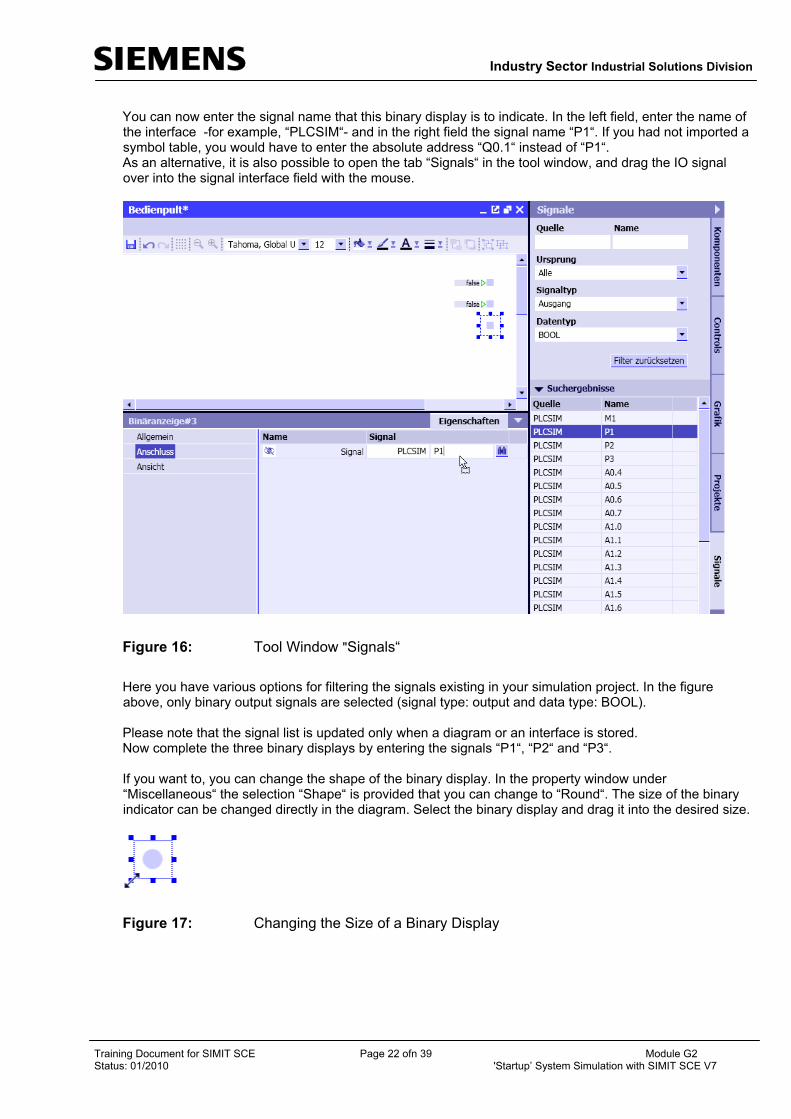
You can now enter the signal name that this binary display is to indicate. In the left field, enter the name of the interface -for example, “PLCSIM“- and in the right field the signal name “P1“. If you had not imported a symbol table, you would have to enter the absolute address “Q0.1“ instead of “P1“. As an alternative, it is also possible to open the tab “Signals“ in the tool window, and drag the IO signal over into the signal interface field with the mouse.
Figure 16: Tool Window "Signals“
Here you have various options for filtering the signals existing in your simulation project. In the figure above, only binary output signals are selected (signal type: output and data type: BOOL). Please note that the signal list is updated only when a diagram or an interface is stored. Now complete the three binary displays by entering the signals “P1“, “P2“ and “P3“. If you want to, you can change the shape of the binary display. In the property window under “Miscellaneous“ the selection “Shape“ is provided that you can change to “Round“. The size of the binary indicator can be changed directly in the diagram. Select the binary display and drag it into the desired size.
Figure 17: Changing the Size of a Binary Display
Training Document for SIMIT SCE Page 22 ofn 39 Module G2 Status: 01/2010 'Startup’ System Simulation with SIMIT SCE V7

Industry Sector Industrial Solutions Division
Now add a control “switch“ to your diagram and parameterize the switch with the signal “F0“ as well as a control “Button“ that has to be parameterized with the signal “S1“. If you want to drag the signals from the tab “Signals“, make sure that the filter settings are set correctly. All filter settings can be cleared with the button “Reset filters“. If you now restart the simulation, you can access these signals from your diagram.
Figure 18: Operator Panel
Please note here also that the PLC program responds to the input “F0“ and resets the output “P1“. Before you continue, close the simulation again by clicking on the symbol or by selecting the menu option “Close simulation“.
Training Document for SIMIT SCE Page 23 ofn 39 Module G2 Status: 01/2010 'Startup’ System Simulation with SIMIT SCE V7

Industry Sector Industrial Solutions Division
5.3.4 Simulation of the Movable Safety Screen
Next, we are going to generate the simulation of the moveable safety screen (guard). This task consists of two parts: The actual function which consists of operating a button that generates a time delayed indication “Safety screen closed“, and a corresponding visual display that shows the process. Set up a new diagram for the function, and call it “Function“, for example.
Figure 19: New Diagram “Function“
The motion of the guard is simulated with a ramp function that corresponds to the vertical position of the guard. A matching component “Ramp“ is provided in the tool window in the tab “Components“ under “STANDARD | AnalogExtended“. Drag this component into your diagram.
Figure 20: Component “Ramp“
Training Document for SIMIT SCE Page 24 ofn 39 Module G2 Status: 01/2010 'Startup’ System Simulation with SIMIT SCE V7

Industry Sector Industrial Solutions Division
This component calculates a ramp value that runs during the settable time “T“ from the lower limit “LL“ to the upper limit “UL“ if the input “UP (+)“ is assigned the value “TRUE“ and vice versa, if the input “DOWN (-)“ is assigned “TRUE“. Whether one of these two limits is reached is signaled at the outputs of the component. Since the safety screen and therefore this ramp is to be operated with a single switch, the switch signal has to be used once directly, and a second time it has to be wired negated. One option to implement this consists of using a “BConnector“ from the component library “CONNECTORS“ and a negation “NOTc“ from the “STANDARD | BinaryBasic“:
Figure 21: Components “Ramp“, “BConnector“ and “NOTc“
Move the negation to the input of the ramp in a way that the red triangle of the negation overlaps with the green input of the ramp. In this way, the two connections are connected to each other. Take note that you are grabbing the small negation component itself and not its connection; otherwise, you will not be able to
move it. If necessary, enlarge the diagram with the symbol from the symbol bar.
Figure 22: Component “Ramp“ with Negated Input
The two connections that are still missing can be established with signal lines. Click on the output of the BConnector and then on the input that is to be connected, or drag it from one connection to the other.
Figure 23: Wiring the Component Ramp
Training Document for SIMIT SCE Page 25 ofn 39 Module G2 Status: 01/2010 'Startup’ System Simulation with SIMIT SCE V7

Industry Sector Industrial Solutions Division
Since the ramp is to be controlled by means of the BConnector, it would be useful to assign it a corresponding name, such as “Screen“. To this end, select the BConnector and in the property window, under the category “General“, overwrite the automatically assigned name “BConnector#1“ with “Screen“.
Figure 24: Name of a Component
Now, we still need the indication (B1) to the controller that the safety screen is closed. Here also, this connection can be established in the simplest way by using the tool window “Signals“. Drag the signal “B1“ to your diagram without releasing it! You will see that the SIMIT SCE initially offers to set up controls for this signal. However, in this case you will need a periphery connector. For that reason, keep the SHIFT key pressed in addition, and only then release the mouse key. Then connect the periphery connector generated in this way with the ramp.
Figure 25: Complete Wiring
Training Document for SIMIT SCE Page 26 ofn 39 Module G2 Status: 01/2010 'Startup’ System Simulation with SIMIT SCE V7

Industry Sector Industrial Solutions Division
Finally, we lower the default value for the execution time of the ramp to 2 seconds. This can be done directly in the diagram by double clicking on the blue colored field in front of input “T“ and overwriting the value with “2“. Now, add the switch for the safety screen to the operator panel. If the diagram “Operator panel“ is still open, you can fetch the switch back into the work area by means of the tabs at the lower screen edge.
Figure 26: Tabs for Switching the Work Area
Here, as an example, a switch with freely designed images is to be used. To this end, drag the “Switch with image“ from the tool window “Controls”. Here also, tThe signal interfacing is to not to be visible, but be executed invisibly on the input “IN“ of our BConnector with the name “Screen“.
Figure 27: Signal Interface of the Switch with Image
In the category “View“, select images to be represented (see Figure 28). The images, used here as an example, are located on the SIMIT SCE installation CD in the folder “Examples“.
Figure 28: Specifying the Images to be Represented
Training Document for SIMIT SCE Page 27 ofn 39 Module G2 Status: 01/2010 'Startup’ System Simulation with SIMIT SCE V7

Industry Sector Industrial Solutions Division
The check mark “Adapt to image size“ is important so that the images are shown in their original size. When you start the simulation you can now see how two seconds after operating the image switch, the indication arrives in the controller.
Figure 29: Indication of the Lowered Safety Screen
Before continuing, close the simulation again!
Training Document for SIMIT SCE Page 28 ofn 39 Module G2 Status: 01/2010 'Startup’ System Simulation with SIMIT SCE V7
Industry Sector Industrial Solutions Division
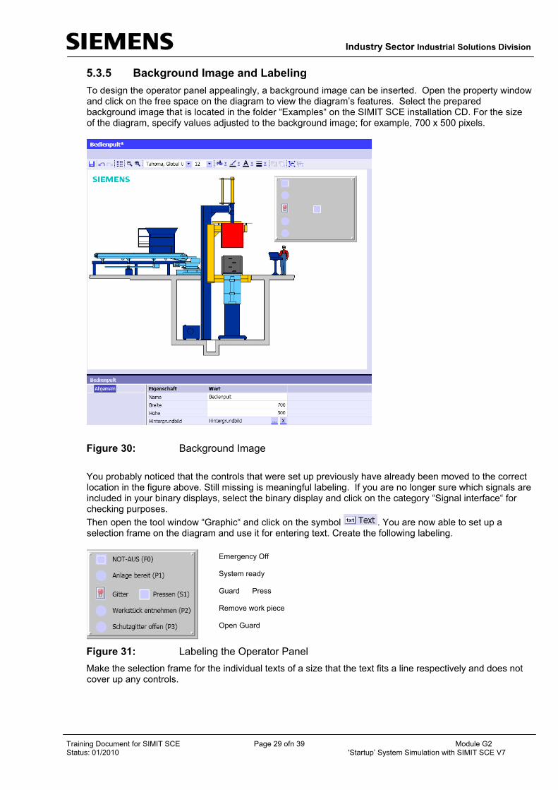
5.3.5 Background Image and Labeling To design the operator panel appealingly, a background image can be inserted. Open the property window and click on the free space on the diagram to view the diagram’s features. Select the prepared background image that is located in the folder “Examples“ on the SIMIT SCE installation CD. For the size of the diagram, specify values adjusted to the background image; for example, 700 x 500 pixels.
Figure 30: Background Image
You probably noticed that the controls that were set up previously have already been moved to the correct location in the figure above. Still missing is meaningful labeling. If you are no longer sure which signals are included in your binary displays, select the binary display and click on the category “Signal interface“ for checking purposes. Then open the tool window “Graphic“ and click on the symbol . You are now able to set up a selection frame on the diagram and use it for entering text. Create the following labeling.
Emergency Off System ready Guard Press Remove work piece Open Guard
Figure 31: Labeling the Operator Panel Make the selection frame for the individual texts of a size that the text fits a line respectively and does not cover up any controls.
Training Document for SIMIT SCE Page 29 ofn 39 Module G2 Status: 01/2010 'Startup’ System Simulation with SIMIT SCE V7
Industry Sector Industrial Solutions Division
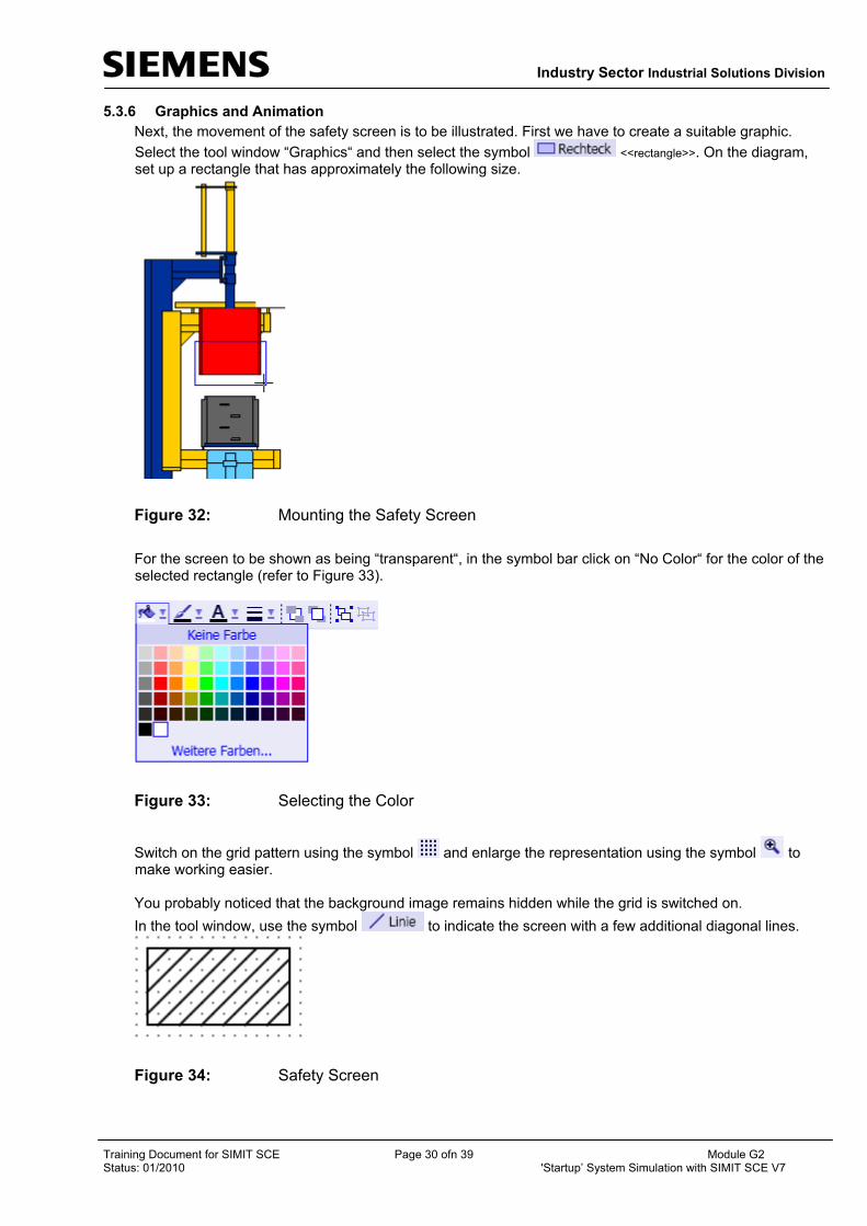
5.3.6 Graphics and Animation Next, the movement of the safety screen is to be illustrated. First we have to create a suitable graphic. Select the tool window “Graphics“ and then select the symbol <<rectangle>>. On the diagram, set up a rectangle that has approximately the following size.
Figure 32: Mounting the Safety Screen
For the screen to be shown as being “transparent“, in the symbol bar click on “No Color“ for the color of the selected rectangle (refer to Figure 33).
Figure 33: Selecting the Color
Switch on the grid pattern using the symbol and enlarge the representation using the symbol to make working easier. You probably noticed that the background image remains hidden while the grid is switched on. In the tool window, use the symbol to indicate the screen with a few additional diagonal lines.
Figure 34: Safety Screen
Training Document for SIMIT SCE Page 30 ofn 39 Module G2 Status: 01/2010 'Startup’ System Simulation with SIMIT SCE V7

Industry Sector Industrial Solutions Division
Select the outer rectangle one more time and apply to it a line thickness of 2 points (2.0 Pt).
Figure 35: Setting the Line Thickness
Since the safety screen is to be moved as one unit, group the rectangle and all diagonal lines by drawing a
selection frame around the graphic elements and then click on the symbol in the symbol bar. Then, switch the grid pattern off again. The safety screen should look something like this:
Figure 36: Safety Screen as a Grouped Graphic
Training Document for SIMIT SCE Page 31 ofn 39 Module G2 Status: 01/2010 'Startup’ System Simulation with SIMIT SCE V7

Industry Sector Industrial Solutions Division
Finally, we are going to animate this picture; i.e., it is to be put in motion depending on the ramp value. To this end, select the safety screen and open the property window. In the property window, double click on the uppermost entry “New animation“ and select “Motion“.
Figure 37: Selecting the Animation Type
You are now in a mode where you can specify the direction and the amount of the shift. Hold the SHIFT key to permit only vertical or horizontal motion, and drag the safety screen a little downward.
Figure 38: Specifying the Motion
Training Document for SIMIT SCE Page 32 ofn 39 Module G2 Status: 01/2010 'Startup’ System Simulation with SIMIT SCE V7

Industry Sector Industrial Solutions Division
Enter output “Y“ of ramp “Ramp#1“ as the signal that is to effect this motion, or drag this signal from the tool window “Signals“ over.
Figure 39: Animation Signal
Exit the animation mode by clicking anywhere in the diagram. If you start the simulation now, you are able to move the safety screen up and down by using the
switch . Before you continue, close the simulation.
5.3.7 Simulation of the Punch
The punch is simulated in a similar manner. On the function chart, a second ramp is needed which in this case is operated by the controller.
Figure 40: Function to which the Punch is Added
Training Document for SIMIT SCE Page 33 ofn 39 Module G2 Status: 01/2010 'Startup’ System Simulation with SIMIT SCE V7

Industry Sector Industrial Solutions Division
Please take note that it is possible to copy components very simply by dragging an existing component off the chart while holding the Ctrl key. To visualize the motion of the punch, trace it with a few rectangles and group these rectangles.
Figure 41: Punch
As animation signal, use the output of the second ramp.
Figure 42: Animation of the Punch
Training Document for SIMIT SCE Page 34 ofn 39 Module G2 Status: 01/2010 'Startup’ System Simulation with SIMIT SCE V7

Industry Sector Industrial Solutions Division
Since the punch was drawn last, it is situated over the safety screen. To correct this, select the punch and move it to the background with the symbol . This concludes this application example. Now you can test whether the controller performs correctly. Check, for example, whether the press can be operated if the safety guard is open!
Punch
Safety Guard
Figure 43: Completed Application Example “Press”
Training Document for SIMIT SCE Page 35 ofn 39 Module G2 Status: 01/2010 'Startup’ System Simulation with SIMIT SCE V7

Industry Sector Industrial Solutions Division
6. Project Management
6.1 Archived Projects
It is possible to combine SIMIT SCE projects into a single file and save them in this way as an archived project, or copy them to another computer. With the menu “Archive | Project“, an opened project can be stored as a SIMIT SCE archive. The SIMIT SCE archive has the file extension “ .simarc“. To unpack a SIMIT SCE project, click on the menu entry “De-archive project“. The destination folder for the de-archived project can be freely selected.
Figure 44: De-Archiving a SIMIT SCE Project
Training Document for SIMIT SCE Page 36 ofn 39 Module G2 Status: 01/2010 'Startup’ System Simulation with SIMIT SCE V7

Industry Sector Industrial Solutions Division
6.2 SIMIT4Students
A special feature of the SIMIT SCE is that it is possible to pass on executable simulations to students or trainees. In an executable simulation, exactly one selected plan of the entire SIMIT SCE project is visible. For that reason, it is advisable to set up the SIMIT SCE project in such a way that all information and operator elements that are made available to the student are assembled in one chart. In the project window, open the context menu of this chart and select the entry “SIMIT4Students“. The executable simulation gets the file extension “.simit4S“.
Figure 45: Passing on a SIMIT SCE Project as Executable Simulation
Training Document for SIMIT SCE Page 37 ofn 39 Module G2 Status: 01/2010 'Startup’ System Simulation with SIMIT SCE V7

Industry Sector Industrial Solutions Division
Before the students can use this executable simulation, the SIMIT SCE execution time environment has to be installed (refer to Section 0). Your students can use only executable simulations that were generated with a SIMIT SCE installation with your license number. If you are using SIMIT SCE in the class room where the student computers are networked via Ethernet with the computer on which the SIMIT SCE is installed, the students can open the executable simulation simply with a double click. The precondition is that the SIMIT SCE was already started. Whether the current SIMIT SCE application is available with the matching dongle is checked automatically. If there is no network connection, the 12-digit password that was displayed during generation has to be entered when starting the executable simulation. For that reason, carefully make note of the password in case it is needed.
Figure 46: Generating an Executable Simulation
Training Document for SIMIT SCE Page 38 ofn 39 Module G2 Status: 01/2010 'Startup’ System Simulation with SIMIT SCE V7

Industry Sector Industrial Solutions Division
Training Document for SIMIT SCE Page 39 ofn 39 Module G2 Status: 01/2010 'Startup’ System Simulation with SIMIT SCE V7
It should also be noted that this executable simulation is runnable only for the specified period of six months. However, it is possible to generate an executable simulation again for your students at a later time as often as required. The simulation password is queried only if the student PC is not able to set up an Ethernet connection to the computer on which the SIMIT SCE is running (refer to Figure 47). The executable simulation is opened in a window that contains exactly the previously selected plan. The simulation is started automatically. To end the simulation, the window simply has to be closed (refer to Figure 48).
Figure 47: Stating the Executable Simulation with a Password
Figure 48: Executable Simulation on the Student Computer