transmission planning
DESCRIPTION
Transmission PlanningTRANSCRIPT
EXPLAIN v3.0 - Nokia 2001 – DVassena
5. Transmission Planning5. Transmission Planning
Summary
• Technologies
• Radio Network Planning Process
• Radio Media & Model Tuning
• Network Dimensioning
• Transmission Planning
• Parameter Planning & Optimisation
• Network Capacity Evolution
• Planning Tools
EXPLAIN v3.0 - Nokia 2001 – DVassena
5. Transmission Planning5. Transmission Planning
Transmission PlanningEXPLAIN CHAPTER 5
• Transmission Planning (3)
• Network Topologies (2)
• Microwave Links (8)
• Leased Lines (3)
• Cross Connects (3)
• Transmission Techniques (4)
EXPLAIN v3.0 - Nokia 2001 – DVassena
5. Transmission Planning5. Transmission Planning
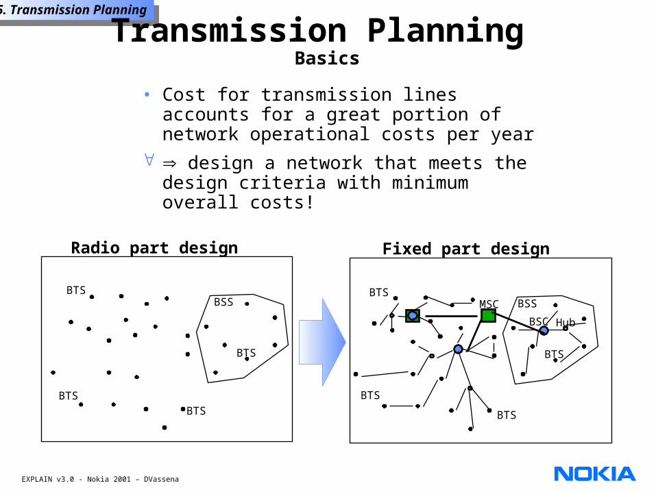
• Cost for transmission lines accounts for a great portion of network operational costs per year
design a network that meets the design criteria with minimum overall costs!
Fixed part design
MSC
BSC Hub
BTS
BSS
BTS
BTS
BTS
Radio part design
BTS
BSS
BTS
BTS
BTS
Transmission Planning Basics
EXPLAIN v3.0 - Nokia 2001 – DVassena
5. Transmission Planning5. Transmission Planning
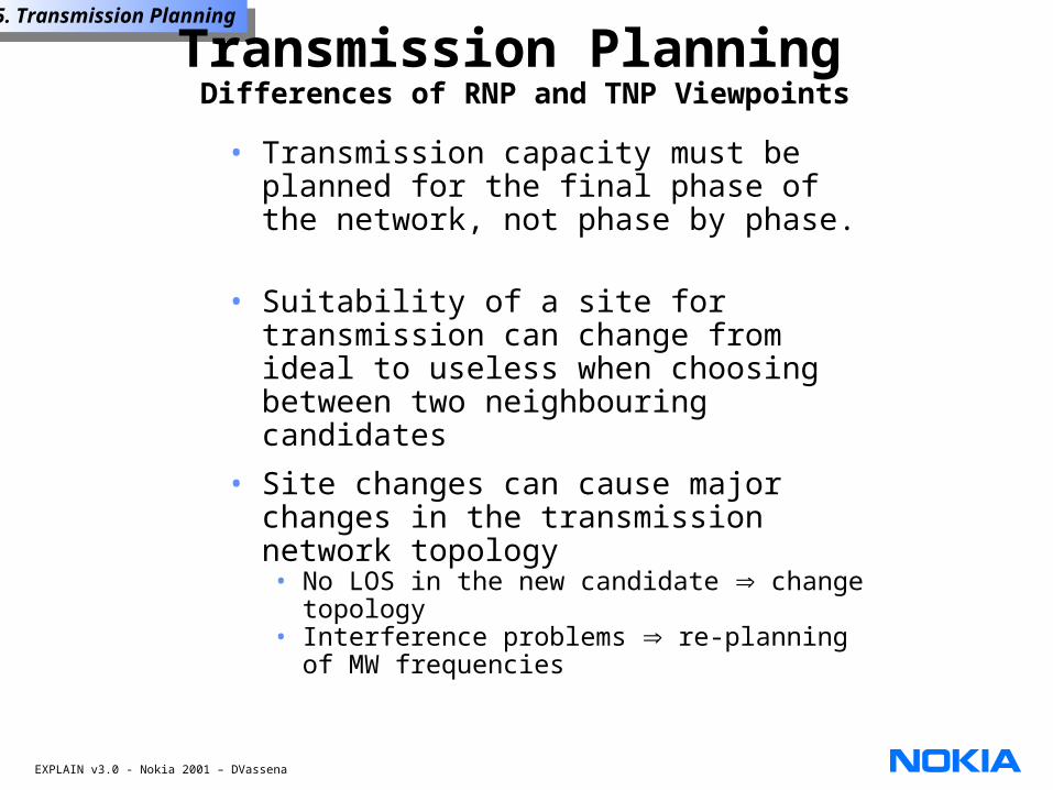
Transmission Planning Differences of RNP and TNP Viewpoints
• Transmission capacity must be planned for the final phase of the network, not phase by phase.
• Suitability of a site for transmission can change from ideal to useless when choosing between two neighbouring candidates
• Site changes can cause major changes in the transmission network topology• No LOS in the new candidate change
topology• Interference problems re-planning of
MW frequencies
EXPLAIN v3.0 - Nokia 2001 – DVassena
5. Transmission Planning5. Transmission Planning
Transmission Planning Input Data
Customer input• Allowed unavailability and performance
figures
• Transmission media requirements: own network / leased line
• Blocking probabilities
• Protection level and type
• Existing transmission infrastructure
• Growth estimate and/or required spare capacity
Radio Network Planning input• Number of BTSs
• Number of TRXs / BTS
• Nominal site locations
EXPLAIN v3.0 - Nokia 2001 – DVassena
5. Transmission Planning5. Transmission Planning
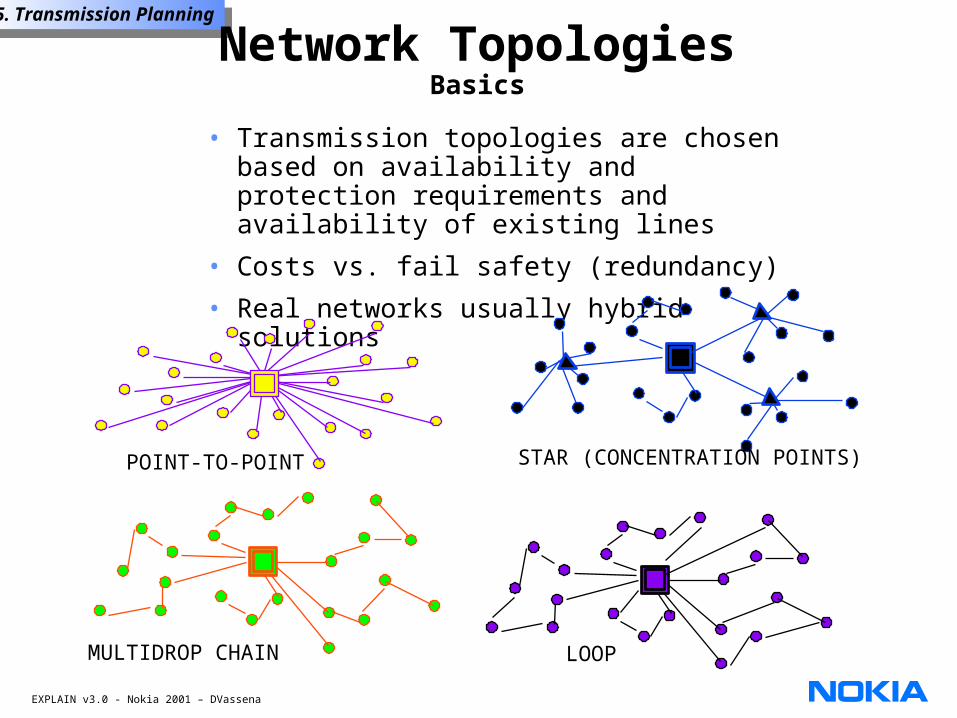
Network TopologiesBasics
• Transmission topologies are chosen based on availability and protection requirements and availability of existing lines
• Costs vs. fail safety (redundancy)
• Real networks usually hybrid solutions
POINT-TO-POINT
MULTIDROP CHAIN LOOP
STAR (CONCENTRATION POINTS)
EXPLAIN v3.0 - Nokia 2001 – DVassena
5. Transmission Planning5. Transmission Planning
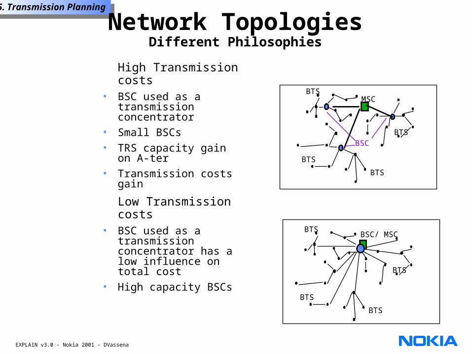
Network TopologiesDifferent Philosophies
High Transmission costs
• BSC used as a transmission concentrator
• Small BSCs• TRS capacity gain on
A-ter • Transmission costs
gain
Low Transmission costs
• BSC used as a transmission concentrator has a low influence on total cost
• High capacity BSCs
MSC
BTSBSC
BTS
BTS
BTS
BSC/ MSC
BTS
BTS
BTS
BTS
EXPLAIN v3.0 - Nokia 2001 – DVassena
5. Transmission Planning5. Transmission Planning
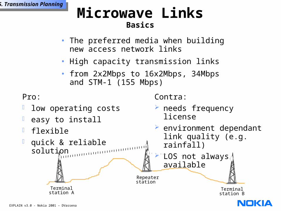
Microwave LinksBasics
• The preferred media when building new access network links
• High capacity transmission links
• from 2x2Mbps to 16x2Mbps, 34Mbps and STM-1 (155 Mbps)
Contra: needs frequency license environment dependant
link quality (e.g. rainfall) LOS not always available
Pro: low operating costs easy to install flexible quick & reliable solution
Terminalstation A
Terminalstation B
Repeaterstation
EXPLAIN v3.0 - Nokia 2001 – DVassena
5. Transmission Planning5. Transmission Planning
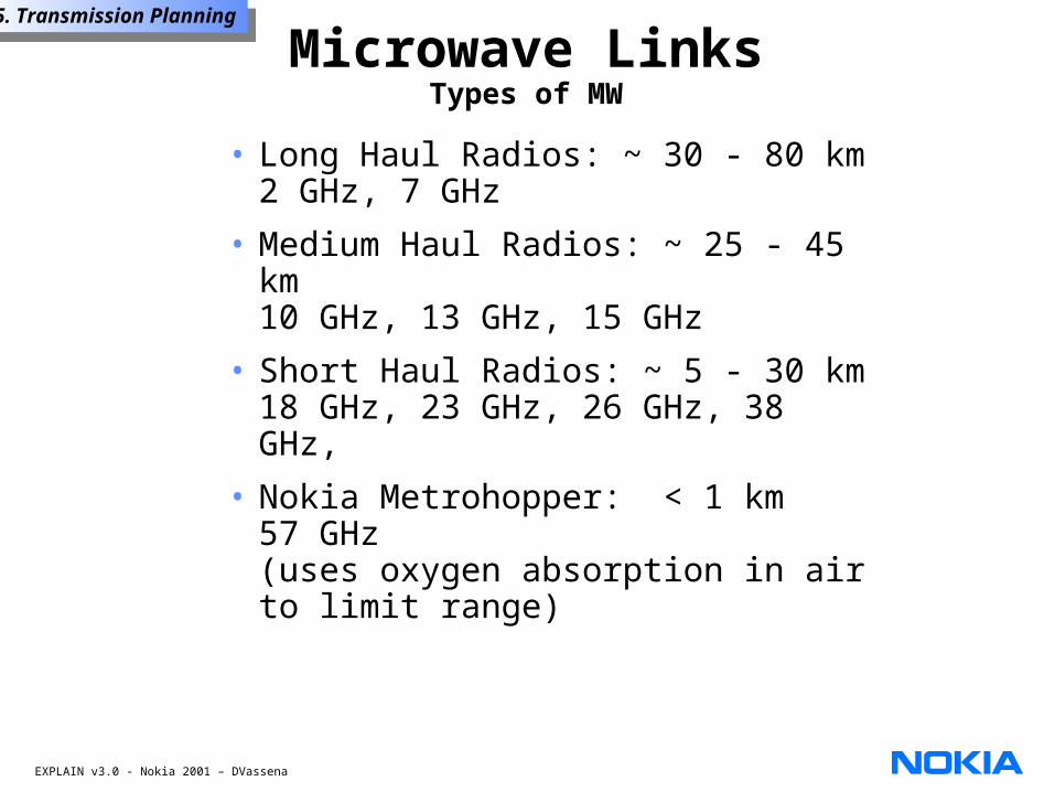
Microwave LinksTypes of MW
• Long Haul Radios: ~ 30 - 80 km2 GHz, 7 GHz
• Medium Haul Radios: ~ 25 - 45 km10 GHz, 13 GHz, 15 GHz
• Short Haul Radios: ~ 5 - 30 km18 GHz, 23 GHz, 26 GHz, 38 GHz,
• Nokia Metrohopper: < 1 km 57 GHz (uses oxygen absorption in air to limit range)
EXPLAIN v3.0 - Nokia 2001 – DVassena
5. Transmission Planning5. Transmission Planning
Microwave LinksModulation Methods
PSK - Phase Shift Keying• there are several levels of PSK (2-PSK, 4-
PSK, …)
FSK - Frequency Shift Keying• fixed frequency for 0s and another one
for 1s
QAM - Quadrature Amplitude Modulation
• a mixture of phase and amplitude modulation
EXPLAIN v3.0 - Nokia 2001 – DVassena
5. Transmission Planning5. Transmission Planning
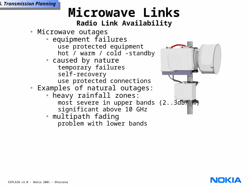
• Microwave outages• equipment failures
use protected equipmenthot / warm / cold -standby
• caused by naturetemporary failuresself-recoveryuse protected connections
• Examples of natural outages:• heavy rainfall zones:
most severe in upper bands (2..3dB/km)significant above 10 GHz
• multipath fadingproblem with lower bands
Microwave LinksRadio Link Availability
EXPLAIN v3.0 - Nokia 2001 – DVassena
5. Transmission Planning5. Transmission Planning
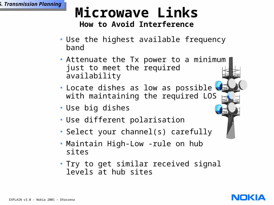
Microwave LinksHow to Avoid Interference
• Use the highest available frequency band
• Attenuate the Tx power to a minimum just to meet the required availability
• Locate dishes as low as possible with maintaining the required LOS
• Use big dishes
• Use different polarisation
• Select your channel(s) carefully
• Maintain High-Low -rule on hub sites
• Try to get similar received signal levels at hub sites
EXPLAIN v3.0 - Nokia 2001 – DVassena
5. Transmission Planning5. Transmission Planning
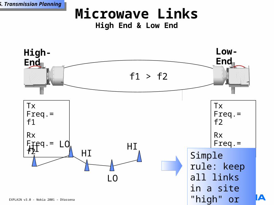
High-End
Low-End
Tx Freq.= f1
Rx Freq.= f2
Tx Freq.= f2
Rx Freq.= f1
f1 > f2
HIHI HILO
LO
Simple rule: keep all links in a site "high" or "low"
Microwave LinksHigh End & Low End
EXPLAIN v3.0 - Nokia 2001 – DVassena
5. Transmission Planning5. Transmission Planning
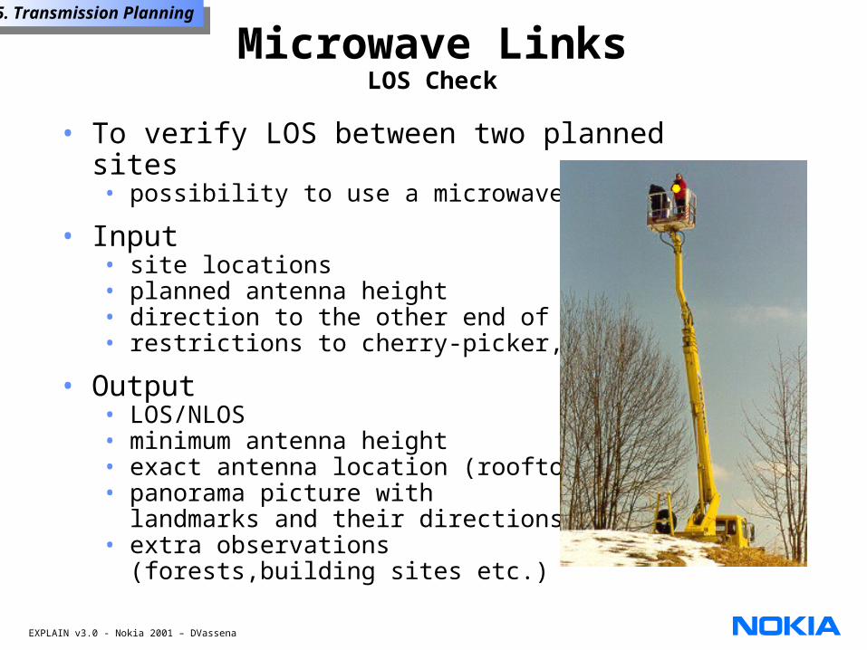
• To verify LOS between two planned sites• possibility to use a microwave link
• Input• site locations• planned antenna height• direction to the other end of link• restrictions to cherry-picker, etc.
• Output• LOS/NLOS• minimum antenna height• exact antenna location (rooftop)• panorama picture with
landmarks and their directions• extra observations
(forests,building sites etc.)
Microwave LinksLOS Check
EXPLAIN v3.0 - Nokia 2001 – DVassena
5. Transmission Planning5. Transmission Planning
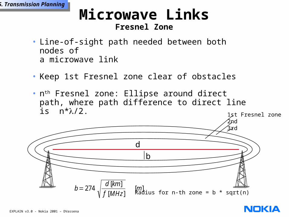
• Line-of-sight path needed between both nodes of a microwave link
• Keep 1st Fresnel zone clear of obstacles
• nth Fresnel zone: Ellipse around direct path, where path difference to direct line is n*/2.
d
b
bd km
f MHzm274
[ ]
[ ][ ]
1st Fresnel zone2nd 3rd
Radius for n-th zone = b * sqrt(n)
Microwave LinksFresnel Zone
EXPLAIN v3.0 - Nokia 2001 – DVassena
5. Transmission Planning5. Transmission Planning
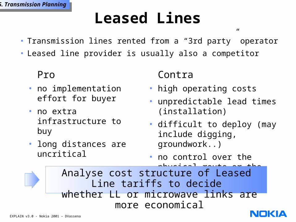
Leased Lines• Transmission lines rented from a “3rd party” operator
• Leased line provider is usually also a competitor
Contra• high operating costs
• unpredictable lead times (installation)
• difficult to deploy (may include digging, groundwork..)
• no control over the physical route or the quality of the link
Pro• no implementation
effort for buyer
• no extra infrastructure to buy
• long distances are uncritical
Analyse cost structure of Leased Line tariffs to decide
whether LL or microwave links are more economical
EXPLAIN v3.0 - Nokia 2001 – DVassena
5. Transmission Planning5. Transmission Planning
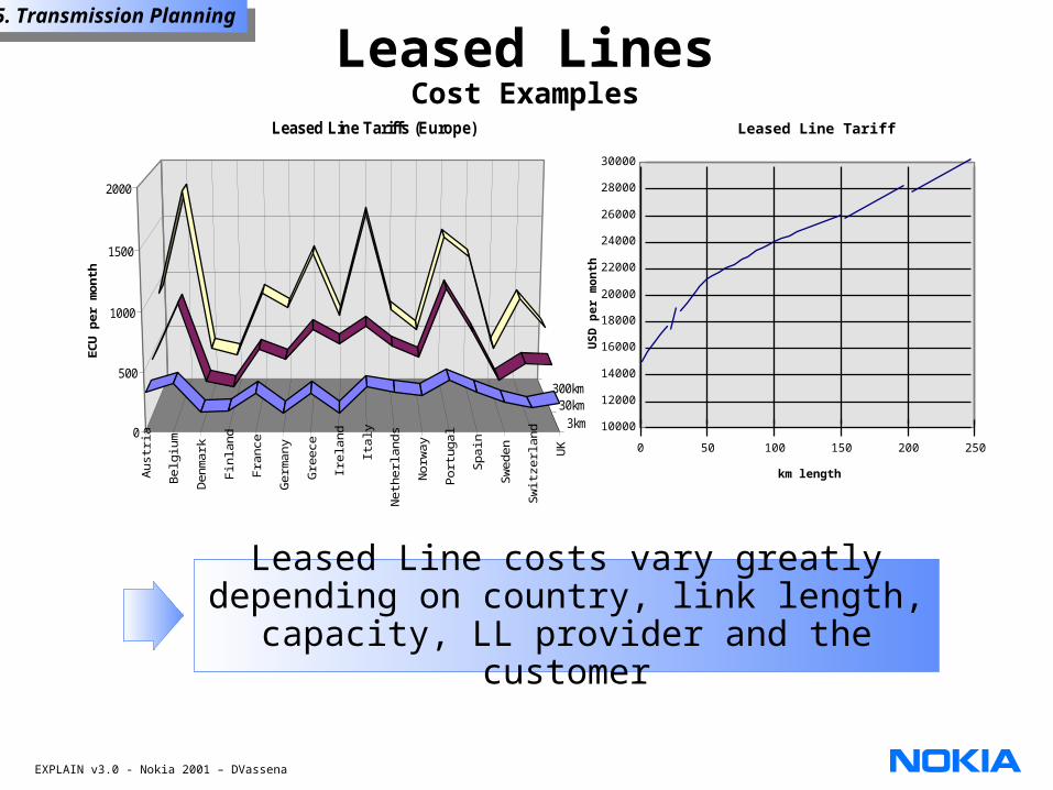
Leased LinesCost Examples
Aus
tria
Bel
gium
Den
mar
k
Finl
and
Fran
ce
Ger
man
y
Gre
ece
Irela
nd Italy
Net
herla
nds
Nor
way
Por
tuga
l
Spa
in
Sw
eden
Sw
itzer
land U
K
3km30km
300km
0
500
1000
1500
2000
EC
U p
er m
onth
Leased Line Tariffs (Europe)
3km
30km
300km
Leased Line Tariff
10000
12000
14000
16000
18000
20000
22000
24000
26000
28000
30000
0 50 100 150 200 250
km length
US
D p
er m
on
thLeased Line costs vary greatly
depending on country, link length, capacity, LL provider and the customer
EXPLAIN v3.0 - Nokia 2001 – DVassena
5. Transmission Planning5. Transmission Planning
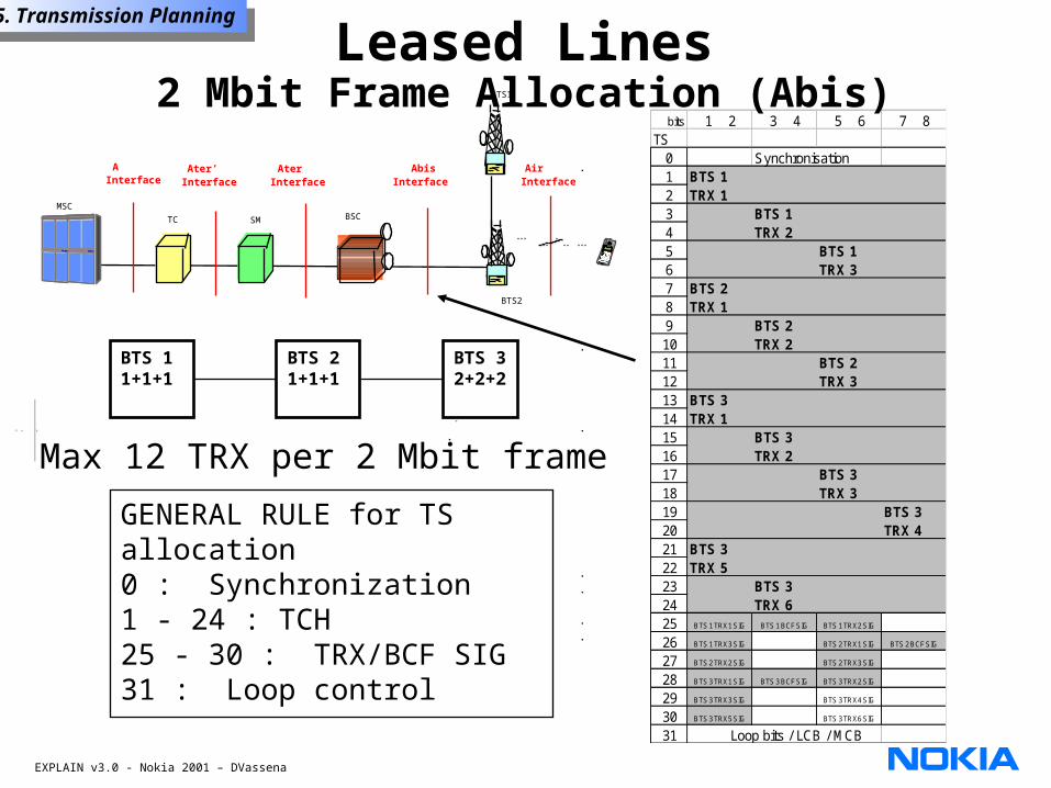
GENERAL RULE for TS allocation0 : Synchronization1 - 24 : TCH25 - 30 : TRX/BCF SIG31 : Loop control
Max 12 TRX per 2 Mbit frame
AbisInterface
AirInterface
BSCMSC
AInterface
Ater’Interface
TC SM
AterInterface
BTS2
BTS1
bits 1 2 3 4 5 6 7 8TS
0 Synchronisation1 BTS 12 TRX 13 BTS 14 TRX 25 BTS 16 TRX 37 BTS 28 TRX 19 BTS 210 TRX 211 BTS 212 TRX 313 BTS 314 TRX 115 BTS 316 TRX 217 BTS 318 TRX 319 BTS 320 TRX 421 BTS 322 TRX 523 BTS 324 TRX 625 BTS 1 TRX 1 SIG BTS 1 BCF SIG BTS 1 TRX 2 SIG
26 BTS 1 TRX 3 SIG BTS 2 TRX 1 SIG BTS 2 BCF SIG
27 BTS 2 TRX 2 SIG BTS 2 TRX 3 SIG
28 BTS 3 TRX 1 SIG BTS 3 BCF SIG BTS 3 TRX 2 SIG
29 BTS 3 TRX 3 SIG BTS 3 TRX 4 SIG
30 BTS 3 TRX 5 SIG BTS 3 TRX 6 SIG
31 Loop bits / LCB / MCB
BTS 11+1+1
BTS 21+1+1
BTS 32+2+2
Leased Lines2 Mbit Frame Allocation (Abis)
EXPLAIN v3.0 - Nokia 2001 – DVassena
5. Transmission Planning5. Transmission Planning
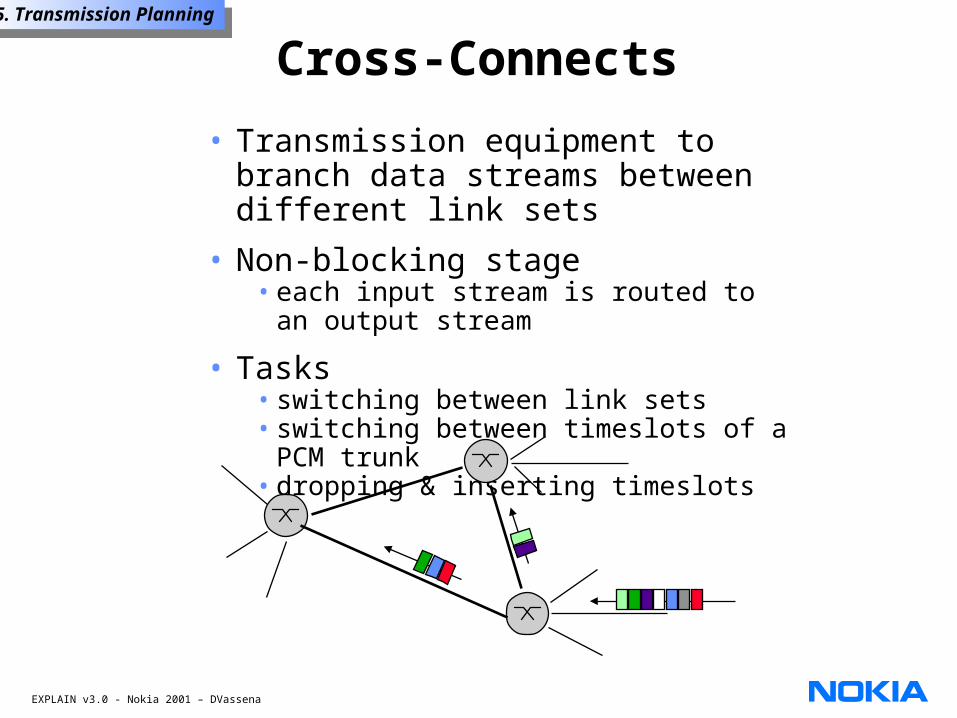
Cross-Connects
• Transmission equipment to branch data streams between different link sets
• Non-blocking stage• each input stream is routed to an
output stream
• Tasks• switching between link sets • switching between timeslots of a PCM
trunk• dropping & inserting timeslots
EXPLAIN v3.0 - Nokia 2001 – DVassena
5. Transmission Planning5. Transmission Planning
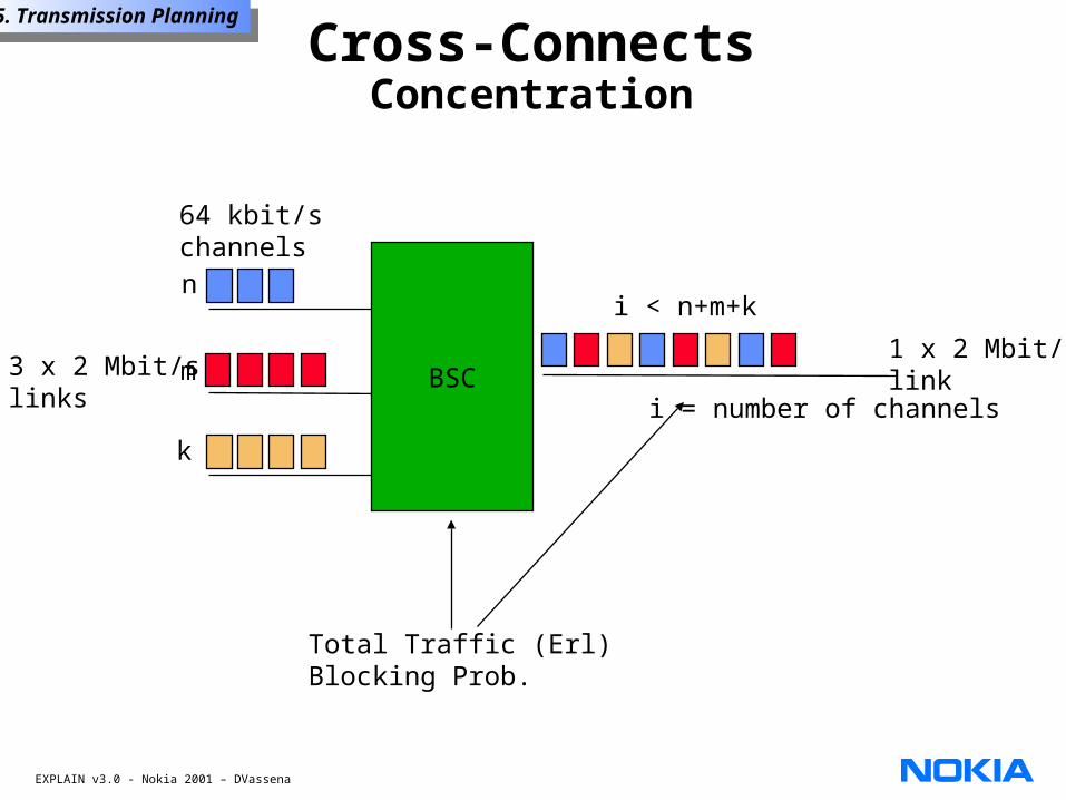
3 x 2 Mbit/slinks
64 kbit/schannels
1 x 2 Mbit/slink
n
m
k
i < n+m+k
BSC
Total Traffic (Erl)Blocking Prob.
i = number of channels
Cross-ConnectsConcentration
EXPLAIN v3.0 - Nokia 2001 – DVassena
5. Transmission Planning5. Transmission Planning
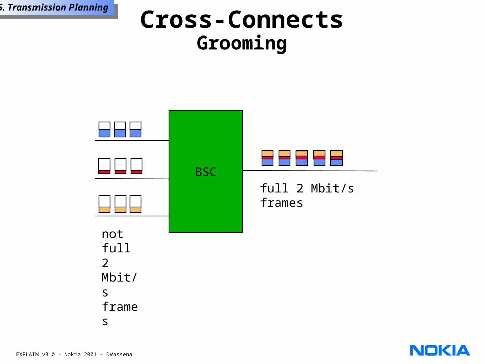
full 2 Mbit/s framesBSC
not full 2 Mbit/s frames
Cross-ConnectsGrooming
EXPLAIN v3.0 - Nokia 2001 – DVassena
5. Transmission Planning5. Transmission Planning
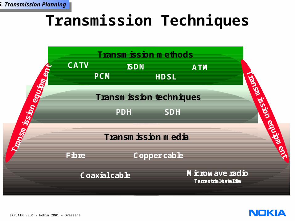
Transmission media
Transmission techniques
Transmission methods
Fibre
Coaxial cable
Copper cable
Microwave radioTerrestrial/satellite
PDH SDH
PCMISDN ATM
HDSL
CATV
Transmission Techniques
EXPLAIN v3.0 - Nokia 2001 – DVassena
5. Transmission Planning5. Transmission Planning
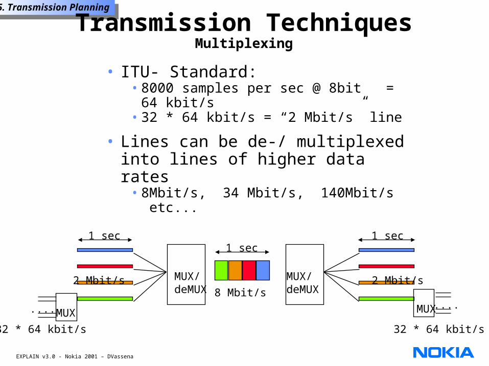
Transmission TechniquesMultiplexing
• ITU- Standard:• 8000 samples per sec @ 8bit = 64
kbit/s• 32 * 64 kbit/s = “2 Mbit/s” line
• Lines can be de-/ multiplexed into lines of higher data rates
• 8Mbit/s, 34 Mbit/s, 140Mbit/s etc...
....
32 * 64 kbit/s
MUX
2 Mbit/s MUX/deMUX
1 sec1 sec
8 Mbit/s2 Mbit/sMUX/
deMUX
1 sec
....
32 * 64 kbit/s
MUX
EXPLAIN v3.0 - Nokia 2001 – DVassena
5. Transmission Planning5. Transmission Planning
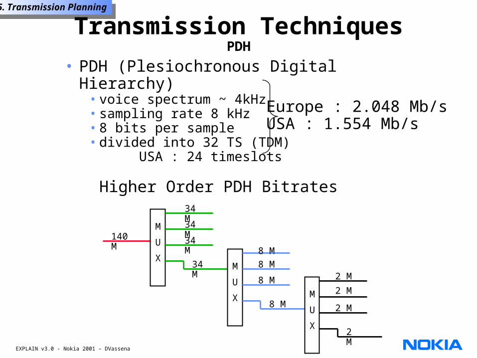
Transmission TechniquesPDH
• PDH (Plesiochronous Digital Hierarchy)• voice spectrum ~ 4kHz• sampling rate 8 kHz• 8 bits per sample• divided into 32 TS (TDM)
USA : 24 timeslots
Higher Order PDH Bitrates
Europe : 2.048 Mb/sUSA : 1.554 Mb/s
M
U
XM
U
X
140 M
34 M
34 M
34 M
34 M
8 M8 M
8 M
8 MM
U
X
2 M
2 M
2 M
2 M
EXPLAIN v3.0 - Nokia 2001 – DVassena
5. Transmission Planning5. Transmission Planning
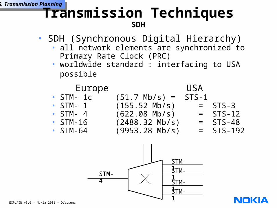
• SDH (Synchronous Digital Hierarchy)• all network elements are synchronized to
Primary Rate Clock (PRC)• worldwide standard : interfacing to USA possible
Europe USA• STM- 1c (51.7 Mb/s) = STS-1• STM- 1 (155.52 Mb/s) = STS-3• STM- 4 (622.08 Mb/s) = STS-12• STM-16 (2488.32 Mb/s) = STS-48• STM-64 (9953.28 Mb/s) = STS-192
STM-4
STM-1STM-1STM-1STM-1
Transmission TechniquesSDH