user manual - simpro · 11.6.1 hydraulic oil ... the user manual describes approved procedures for...
TRANSCRIPT

© 2017 Simpro Handling Equipment Ltd
66 Rangi Road, Takanini 2105, New Zealand
USER MANUAL
Quikstak SP10 Series


User Manual | Quikstak SP10 Series
v54.0 | August 2017 | Page 2
Copyright © 2017 Simpro Handling Equipment Ltd.
No part of this document may be reproduced or transmitted in any form or by any means, electronic,
mechanical, photocopying, recording, or otherwise, without the written permission of the publisher.
For reasons of standards compliance and international conformity, this document uses Système
International (SI) units. These may be converted to their Imperial equivalents as follows:
1 kilogram (kg) = 2.2 pounds (lb)
1 metre (m) = 1000 millimetres (mm) = 39.37 inches (in) = 3.28 feet (ft) = 1.09 yards (yd)
The following textual conventions are used throughout this document:
Text in GREEN indicates a point of interest.
Text in RED indicates a point of warning, or a safety hazard.
Any errors in this document should be reported by email to [email protected].

1 Contents
1 Contents .......................................................................................................................................... 3
2 Introduction .................................................................................................................................... 5
2.1 Key features ................................................................................................................................... 5
2.2 Construction ................................................................................................................................... 5
2.3 Mechanism ..................................................................................................................................... 5
2.4 Environmental restrictions ............................................................................................................. 6
2.5 Important notes ............................................................................................................................. 6
3 Layout Diagram ............................................................................................................................... 7
4 Technical Specifications .................................................................................................................. 8
5 Load Capacity Chart ........................................................................................................................ 9
6 Safety Norms ................................................................................................................................. 11
7 Operation ...................................................................................................................................... 15
7.1 Before operation ..........................................................................................................................15
7.2 Moving the stacker .......................................................................................................................16
7.2.1 Control tiller .................................................................................................................. 16
7.2.2 Slow button ................................................................................................................... 16
7.2.3 Mast safety height ........................................................................................................ 16
7.2.4 Towing ........................................................................................................................... 17
7.3 Pallet handling and stacking .........................................................................................................17
7.4 Using the magic-eye .....................................................................................................................18
7.4.1 Loading product ............................................................................................................ 18
7.4.2 Unloading product ........................................................................................................ 18
7.5 After operation .............................................................................................................................19
8 Battery and Charger ...................................................................................................................... 21
8.1 Charging .......................................................................................................................................21
8.2 Use and maintenance ..................................................................................................................21
8.3 Storage .........................................................................................................................................21
8.4 Charger .........................................................................................................................................22
9 Pre-operation inspection .............................................................................................................. 23
10 Post-operation inspection ......................................................................................................... 24
11 Scheduled Inspections .............................................................................................................. 25

User Manual | Quikstak SP10 Series
v54.0 | August 2017 | Page 4
11.1 Before scheduled inspections ......................................................................................................25
11.2 Weekly scheduled inspection.......................................................................................................25
11.3 Monthly scheduled inspection .....................................................................................................26
11.4 Biannual scheduled inspection ....................................................................................................27
11.5 Brake clearance adjustment procedure .......................................................................................27
11.6 Recommended lubricants ............................................................................................................28
11.6.1 Hydraulic oil .................................................................................................................. 28
11.6.2 Gear oil .......................................................................................................................... 28
11.6.3 Lubricating grease ......................................................................................................... 28
11.7 Consumables and Replacement Periods ......................................................................................28
12 Storage, Loading and Transportation ....................................................................................... 29
12.1 Storage .........................................................................................................................................29
12.2 Lifting, loading and unloading ......................................................................................................29
12.3 Transportation .............................................................................................................................29
13 Troubleshooting Guide ............................................................................................................. 31
14 Common Spare Parts ................................................................................................................ 32
15 Adjusting the Overload Valve ................................................................................................... 33
16 Hydraulic System Schematic ..................................................................................................... 34
17 Electrical System Schematic ...................................................................................................... 35
18 Weekly Maintenance Log .......................................................................................................... 36
19 Monthly Maintenance Log ........................................................................................................ 37
20 Biannual Maintenance Log........................................................................................................ 38

2 Introduction
Congratulations on purchasing a Quikstak SP10 Series electric pallet stacker from Simpro! This stacker is
designed to lift, move and stack heavy pallets on hard level surfaces. It uses batteries and a geared DC
electric motor for motive force, while the forks are lifted by a DC motor powering a hydraulic system.
The electro-hydraulic system ensures that the SP10 is energy-efficient, while also being stable, easy to
operate, safe and very reliable. The powerful 24V 100Ah battery allows the stacker to be used for
extended periods without recharging, and like many electric vehicles, the stacker is quiet and
environmentally friendly.
2.1 Key features Key features of the Quikstak SP10 Series include:
1. The optional ‘magic-eye’ sensor, which automatically adjusts the height of the forks to maintain
an ergonomic work height as product is loaded or unloaded.
2. A weight capacity of 1000kg, and a standard lift height of 1.6 metres (optionally increased to 2.5
or 3.0 metres).
3. Extremely reliable design, requiring very little maintenance.
4. Adjustable straddle legs and adjustable forks.
5. A powerful brushless electric drive motor, suitable for use on ramps or sloping ground.
6. A tiny turning radius of just 1490mm, ideal for constricted spaces.
2.2 Construction The SP10 pallet stacker consists of a steel frame with vertical masts and adjustable outrigger legs,
adjustable steel forks, hydraulic ram, mesh guarding, tiller, power drive unit with vertical steered wheel,
two outrigger wheels, plastic fascia, control panel, batteries, hydraulic powerpack and electronic control
systems.
2.3 Mechanism When the ‘Raise’ button is pressed, the hydraulic ram is extended, lifting the forks. When the ‘Lower’
button is pressed, the ram is retracted, lowering the forks. By pressing buttons on the tiller, the operator
can move and steer the stacker, and insert the forks under pallets or other loads as required. By raising
the forks, the stacker can then be used to easily lift, move, stack, load or unload the objects.
When fitted with a ‘magic-eye’ system, an infra-red scanner monitors the height of the objects placed on
the forks, automatically adjusting them to maintain the desired working height.

User Manual | Quikstak SP10 Series
v54.0 | August 2017 | Page 6
2.4 Environmental restrictions 1. Height above sea level not more than 1000m;
2. Ambient temperature not higher than +40C and not lower than -25C;
3. At ambient temperatures above 40C, the relative humidity should not exceed 50%; at lower
temperatures, higher relative humidity is permitted;
4. Hard, flat surfaces; pitted and uneven floors will cause steering difficulties.
5. Do not use in flammable, explosive, corrosive, acidic or alkaline environments.
2.5 Important notes Operators must read this user manual carefully before operation.
The user manual shall be kept by the operator, and shall be read by the operator until the
operator is proficient with all aspects of standard use.
Operators must strictly conform to ISO3691 “Safety Specifications of Motor Industrial Vehicles”.
Untrained personnel are not allowed to operate the stacker.
The user manual describes approved procedures for the operation, maintenance, and routine
inspection of the stacker.
If the stacker is to be leased, then the user manual shall accompany the machine at all times.
Please contact your authorized Simpro agent if you encounter any problems.
This manual is a common manual. We reserve the right to modify technology of the electric
stacker. If there is anything in the manual that is not consistent with the actual stacker, the
actual stacker should be considered correct and the manual is only for reference.

3 Layout Diagram

User Manual | Quikstak SP10 Series
v54.0 | August 2017 | Page 8
4 Technical Specifications
Quikstak SP10 Specifications
Model (SKU) SP1016
Magic-eye load height sensor Optional
Rated load capacity ("Q") 1000kg
Load centre distance ("c") 600mm
Load distance, centre of drive axle to fork ("x") 770mm
Fork height, lowered ("h13") 80mm
No. wheels, body 2 (1 drive)
Drive wheel dimensions, body ⌀195mm x 70mm
Balance wheel dimensions, body ⌀150mm x 60mm
No. wheels, outriggers 4
Wheel dimensions, outriggers ⌀98mm x 82mm
Mast height lowered ("h1") 2145mm
Maximum lift height ("h3") 1600mm (options: 2500mm, 3000mm)
Mast height extended ("h4") 2145mm
Height of tiller in drive position, min / max ("h14") 670mm / 1300mm
Overall length ("l1") 1500mm
Length to face of forks ("l2") 660mm
Overall width ("b1") 1132mm - 1532mm (adjustable)
Fork length ("l") 1150mm
Fork width ("e") 100mm
Fork depth ("s") 40mm
Width overall forks ("b5") 200mm - 800mm (adjustable)
Ground clearance, centre of wheelbase ("m2") 35mm
Aisle width for pallets 1000x1200 crossways ("Ast") 2280mm
Aisle width for pallets 800x1200 lengthways ("Ast") 2280mm
Turning radius ("Wa") 1490mm
Travel speed 6.0km/h
Lift speed, laden / unladen 0.12m/s / 0.22m/s
Lowering speed, laden / unladen 0.14m/s / 0.14m/s
Battery voltage / nominal capacity 24V / 100Ah
Battery weight 60kg
Battery dimensions (L x W x H) 329mm x 172mm x 214mm
Service weight 580kg

5 Load Capacity Chart
According to ISO 3691 “Safety Specification of Motor Industrial Vehicles”, load capacity and lifting height
of our SP10 Electric Pallet Stacker are stipulated as follows:
1. When the lifting height of SP10 stacker is below 2500mm inclusive, the maximum load capacity is
the rated capacity. Overloading is prohibited.
2. When the lifting height of SP10 stacker is above 2500mm, the load capacity is less than the rated
bearing capacity. Take the following diagrams as a reference with the rated loads of 1000kg.

User Manual | Quikstak SP10 Series
v54.0 | August 2017 | Page 10

6 Safety Norms
• Before the stacker is deployed, an Operational and Safety Procedure must be formulated, taking into full consideration the actual usage conditions and environment.
• The Operational and Safety Procedure must be fully understood by all staff using the stacker or working in proximity to the stacker.
Operational and Safety Procedure
• Only operators who have received formal training or are authorized may be permitted to drive the stacker.
• All operators must read and understand this manual before using the stacker.
• Never drive the stacker while tired, lacking in concentration or while under the influence of drugs, alcohol or other performance impariring substances.
• Operators must always wear safety shoes and suitable protective clothing. Do not wear loose clothing, as it may be caught, resulting in dangerous entrapment.
• Long hair should be tied back.
• Take time to carefully familiarise yourself with the stacker and its operational characteristics before use.
Personnel
• This electric stacker may only be used indoors on a hard flat floor.
• Never attempt to lift loads or turn the stacker on sloping surfaces.
• The floor should be kept in good condition, with a minimum of traffic.
• The area of operation should be lit to a minimum of 200 lux.
• Operation in flammable, explosive, or corrosive (acidic or alkaline) environments is forbidden.
• Never allow open flame, smoking or other ignition hazards in proximity to the stacker and charger.
• Fire extinguishing appliances shall be available in the places where stacker use and charging is carried out. The extinguishing appliances shall comply with the requirements of extinguishing fire of solid combustible matter and electric apparatus.
Environment

User Manual | Quikstak SP10 Series
v54.0 | August 2017 | Page 12
•Before use, always ensure there are no persons on or near the stacker, other than the operator.
•Never place any part of the body underneath the forks or load.
•Never allow persons to ride or travel on the stacker, other than in an authorised, suitable man-cage.
•Operating this stacker requires the operator's complete attention, as well as unimpeded vision and hearing.
•Focus on the task at hand
•Do not wear dark sunglasses
•Do not wear earplugs or headphones
•Avoid making sharp turns in narrow aisles or constricted spaces.
•This stacker has rear wheel drive and rear wheel steer. Due to this difference from common vehicles, the rear of the stacker swings comparatively quickly when turning. Drive slowly when turning to prevent collision with other objects.
•Avoid abrupt manouvres of any kind when carrying goods. Sharp turns or changes in speed may destabilise the load or the stacker itself.
•When turning, reduce speed to minimise the risk destabilising the load or causing a collision.
•Never drive the stacker when the forks are raised above 500mm. Always keep forks as low as possible when transporting goods.
•Lower the forks to the ground when the stacker is not in use.
•Never raise or lower the forks while driving the stacker.
•Rapidly switching the raise and lower controls may cause damage to the stacker and goods.
•The driver must always have a view of the direction of travel. If the operator's view is obstructed by a large load, drive the stacker backwards, or under the guidance of another trained operator.
•Always request the guidance of another trained operator when manouvering through narrow access routes or aisles.
•Sound the horn, decelerate and drive with caution at crossroads or other situations where the operator's view is limited, or unexpected traffic may appear.
•Take care when operating in high winds as this can cause unexpected instability.
Basic operation
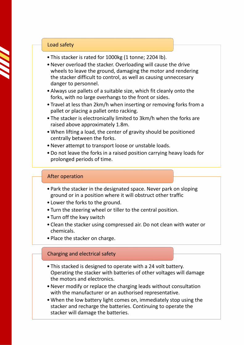
• This stacker is rated for 1000kg (1 tonne; 2204 lb).
• Never overload the stacker. Overloading will cause the drive wheels to leave the ground, damaging the motor and rendering the stacker difficult to control, as well as causing unneccesary danger to personnel.
• Always use pallets of a suitable size, which fit cleanly onto the forks, with no large overhangs to the front or sides.
• Travel at less than 2km/h when inserting or removing forks from a pallet or placing a pallet onto racking.
• The stacker is electronically limited to 3km/h when the forks are raised above approximately 1.8m.
• When lifting a load, the center of gravity should be positioned centrally between the forks.
• Never attempt to transport loose or unstable loads.
• Do not leave the forks in a raised position carrying heavy loads for prolonged periods of time.
Load safety
• Park the stacker in the designated space. Never park on sloping ground or in a position where it will obstruct other traffic
• Lower the forks to the ground.
• Turn the steering wheel or tiller to the central position.
• Turn off the kwy switch
• Clean the stacker using compressed air. Do not clean with water or chemicals.
• Place the stacker on charge.
After operation
• This stacked is designed to operate with a 24 volt battery. Operating the stacker with batteries of other voltages will damage the motors and electronics.
• Never modify or replace the charging leads without consultation with the manufacturer or an authorised representative.
• When the low battery light comes on, immediately stop using the stacker and recharge the batteries. Continuing to operate the stacker will damage the batteries.
Charging and electrical safety

User Manual | Quikstak SP10 Series
v54.0 | August 2017 | Page 14
•All operational surfaces must be clean, safe and reliable in accordance with technical performance of the stacker.
•Moving up slopes, the stacker should be driven fowards, with the forks in front.
•Moving down slopes, the stacker should be driven backwards, with the forks trailing.
•Drive below 4km/h on sloping ground and always be prepared to brake.
•Do not attempt to turn or park the stacker on heavily sloping ground.
•Before operating on a raised structure, ensure the structure has sufficient load bearing capacity to support the stacker.
•When operating on raised structures, always maintain a safety distance from the edge.
•When loading the stacker into an elevator or lift, ensure the elevator has sufficient rated weight capacity. The stacker should be driven in first, with the operator following. At the terminus, the operator should leave the elevator first.
Slopes, ramps and elevated platform safety
•Never operate the stacker if it is malfunctioning or faulty.
•A visual inspection of the stacker should be undertaken on a daily basis.
•An in-depth inspection and functional examination of the stacker should be undertaken on a monthly basis.
•Damaged or missing parts must be repaired or replaced before the stacker is operated.
•All repairs and servicing must be conducted by trained, authorised personnel.
•If the stacker develops a fault and requires repairs, park it out of the way of traffic. Lower the forks to ground level and place a warning sign advising that the stacker is out of operation. Remove the key.
Inspections, faults and repairs
•No modifications or alterations shall be made without the prior written approval of Simpro Handling Equipment Ltd, its authorized representative, or a successor thereof.
•This includes changes affecting, for example braking, steering, visibility and the addition of removable attachments.
•When the manufacturer or its successor approve a modification or alteration, they shall also make and approve appropriate changes to capacity plate, decals, tags and operation and maintenance handbooks.
•Should Simpro Handling Equipment Ltd be no longer in business and there is no successor in the interests of the business, the user may arrange for a modification or alteration to a stacker, provided, however, the user shall:
•Arrange for the modification or alteration to be designed, tested and implemented by an engineer(s) expert in industrial stacker design and safety.
•Maintain a permanent record of the design, test(s) and implementation of the modification or alteration.
•Approve and make appropriate changes to the specification plate(s), decals, tags and instruction handbook.
•Affix a permanent and readily visible label to the stacker stating the manner in which the stacker has been modified or altered together with the date of the modification or alteration, and the name and address of the organisation that accomplished the tasks.
Product modifications and integrity

7 Operation
7.1 Before operation 1. Check that the stacker is in a normal condition.
a. No obvious oil leaks
b. All wheels in contact with ground and rolling normally
c. No blockages, warning lights or other unusual behaviour.
Never attempt to operate the stacker if it is malfunctioning, faulty or damaged
2. Check that the batteries are sufficiently charged.
a. Pull the general power switch out to turn on the general power supply
b. Unlock the electric lock on the handle
c. Check the charge indicator light on the instrument panel of the stacker. If the zero-end
grid is bright, it indicates the batteries are flat and should be charged at once.
Never attempt to operate the stacker with flat batteries as that may damage the batteries or
greatly reduce their service life.
Figure 1
3. Check that the controls are operating normally.
a. Move the control tiller to a vertical position (zone A in Fig 2), and press the raise and
lower buttons to check the forks operate correctly.
b. Move the control tiller to a central position (zone B in Fig 2), and press the drive lever to
slowly accelerate the stacker, then move the tiller to the horizontal position (zone C in
Fig. 2) to ensure the brakes operate correctly.

User Manual | Quikstak SP10 Series
v54.0 | August 2017 | Page 16
c. Move the control tiller to a central position (zone B in Fig 2), drive the stacker slowly
backwards, and press the emergency reverse button (Fig 2) to check that the anti-crush
reversing function works correctly.
Figure 2
Once these checks are completed satisfactorily, the stacker may be placed into operation.
7.2 Moving the stacker
7.2.1 Control tiller The control tiller is used to control the direction of travel and speed of the stacker. To drive the stacker,
the tiller must be at a moderate elevation (zone B in Fig 2). When the tiller is in zone A or zone C, the
stacker is in a power-off status and cannot travel. When the tiller is in zone B and the drive lever is
rotated forwards, the stacker will move forwards. When the lever is rotated backwards, the stacker will
reverse. The further the lever is rotated, the faster the stacker will move in the given direction.
There is a cutoff switch fitted to the tiller-elevation shaft, and an electro-magnetic brake on the
driving motor. Only when the tiller is at an angle between 35° and 45° can the stacker be turned
on and moved. At greater or lesser angles, the drive motor will be powered-off and braked,
although the raise and lower functions are still available.
7.2.2 Slow button As illustrated in Fig 2, there is a button on the underside of the control tiller which is used for operating
the stacker at slow speeds. While this button is pressed, the stacker will move at approximately half the
usual speed. This is useful for delicate operations such as turning sharp corners or loading pallets into
racking. When released, the stacker will immediately resume moving at normal speeds.
7.2.3 Mast safety height The ‘mast safety height’ is about 1.8 metres. While the forks are above this height, the stacker is
electronically limited to approximately 3km/h.

7.2.4 Towing 1. In emergency situations where the stacker needs to be moved while the batteries are
discharged, a suitable tow-rope or cable may be used.
2. Before towing, ensure the electromagnetic brake is disengaged.
3. Do not attempt to lift or carry goods while towing. If the stacker is already carrying a load it
should be removed.
4. When the stacker is placed in storage, the electromagnetic brake musty be re-engaged to ensure
the stacker is braked.
Never attempt to tow the stacker on ramps or heavily sloping ground.
7.3 Pallet handling and stacking Once all checks described in section 7.1 are complete, the stacker may be used to raise, lower, stack and
transport pallets. Correctly used and operated, the Quikstak SP10 will bring great improvements to your
workplace safety and efficiency.
1. Drive the stacker to the pallet(s) which are to be lifted.
2. Approach from a 90-degree angle, taking care to align the stacker so that the forks can slide into
the pallet without striking any cross-members.
3. Stop the stacker while the forks are about 300mm from the pallet. Using the raise and lower
buttons, adjust the forks so that they are at a suitable height to enter the pallet.
4. Slowly drive the stacker forward, taking care not to strike obstacles with the forks or outriggers,
as the forks completely traverse within the pallet.
5. Press the raise button to gently lift the pallet.
6. Slowly back the stacker away, again taking care to avoid any obstacles. The stacker and pallet can
now be driven to the desired destination.
7. At the destination, manoeuvre the stacker so that the pallet is located above its final position.
Care must be taken to avoid collisions with racking or other obstacles.
8. Press the lower button, to gently lower the pallet into place.
9. Once the pallet is visibly secure, press the raise button briefly, to lift the forks 10mm-20mm.
10. Slowly reverse the stacker in a straight line until he forks are completely disengaged from the
pallet. The stacker may now be driven elsewhere.
Unlike most vehicles in common use, the stacker uses rear wheel steering. This means the rear of
the stacker swings comparatively wide and quickly when turning. To minimize the risk of
collisions – especially around pallet racking, or if the operator is unfamiliar with rear-wheel-steer
vehicles – turns should always be conducted slowly and with care.
If the forks continue rising or descending after the corresponding button is released, immediately
press the emergency stop button to cut off power to the stacker. Tow the stacker to a safe
location and call an authorized repair technician to identify and repair the fault.
If the brake stops working or operates abnormally, slowly move the stacker to a safe location and
call an authorized repair technician to identify and repair the fault.
User Manual | Quikstak SP10 Series
v54.0 | August 2017 | Page 18
If the stacker is accidentally driven against a wall or other obstacle in a way that would crush the
operator, the operator’s body will usually press the emergency reverse button. (This button can
also be pressed manually.) The stacker will immediately accelerate a short distance in the
opposing direction to prevent injury.
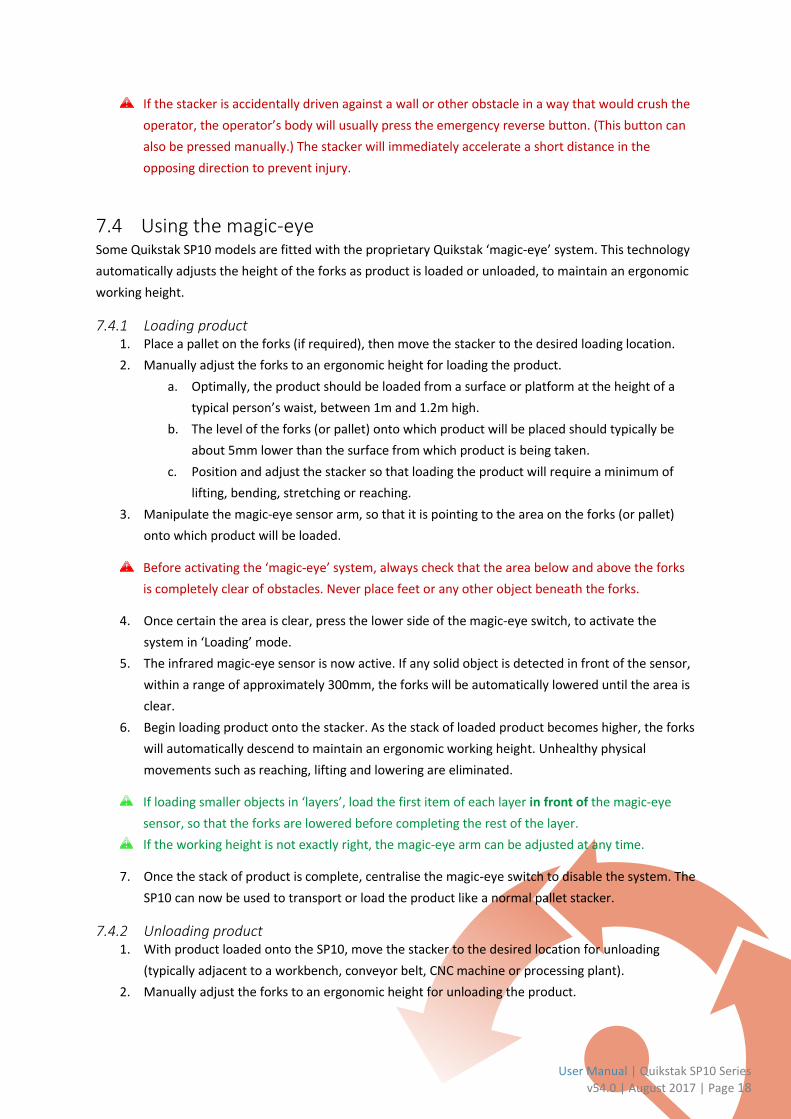
7.4 Using the magic-eye Some Quikstak SP10 models are fitted with the proprietary Quikstak ‘magic-eye’ system. This technology
automatically adjusts the height of the forks as product is loaded or unloaded, to maintain an ergonomic
working height.
7.4.1 Loading product 1. Place a pallet on the forks (if required), then move the stacker to the desired loading location.
2. Manually adjust the forks to an ergonomic height for loading the product.
a. Optimally, the product should be loaded from a surface or platform at the height of a
typical person’s waist, between 1m and 1.2m high.
b. The level of the forks (or pallet) onto which product will be placed should typically be
about 5mm lower than the surface from which product is being taken.
c. Position and adjust the stacker so that loading the product will require a minimum of
lifting, bending, stretching or reaching.
3. Manipulate the magic-eye sensor arm, so that it is pointing to the area on the forks (or pallet)
onto which product will be loaded.
Before activating the ‘magic-eye’ system, always check that the area below and above the forks
is completely clear of obstacles. Never place feet or any other object beneath the forks.
4. Once certain the area is clear, press the lower side of the magic-eye switch, to activate the
system in ‘Loading’ mode.
5. The infrared magic-eye sensor is now active. If any solid object is detected in front of the sensor,
within a range of approximately 300mm, the forks will be automatically lowered until the area is
clear.
6. Begin loading product onto the stacker. As the stack of loaded product becomes higher, the forks
will automatically descend to maintain an ergonomic working height. Unhealthy physical
movements such as reaching, lifting and lowering are eliminated.
If loading smaller objects in ‘layers’, load the first item of each layer in front of the magic-eye
sensor, so that the forks are lowered before completing the rest of the layer.
If the working height is not exactly right, the magic-eye arm can be adjusted at any time.
7. Once the stack of product is complete, centralise the magic-eye switch to disable the system. The
SP10 can now be used to transport or load the product like a normal pallet stacker.
7.4.2 Unloading product 1. With product loaded onto the SP10, move the stacker to the desired location for unloading
(typically adjacent to a workbench, conveyor belt, CNC machine or processing plant).
2. Manually adjust the forks to an ergonomic height for unloading the product.

a. Optimally, the product should be unloaded onto a surface or platform at the height of a
typical person’s waist, between 1m and 1.2m high.
b. The base of the highest ‘layer’ of product should typically be about 5mm higher than the
surface onto which the product is being loaded.
c. Transferring the product from the stacker should require a minimum of lifting, bending,
stretching or reaching.
3. Manipulate the magic-eye sensor arm, so that it is pointing towards the top of the highest ‘layer’
of product.
Before activating the ‘magic-eye’ system, always check that the area below and above the forks
is completely clear of obstacles. Never place feet or any other object beneath the forks.
4. Once certain the area is clear, press the upper side of the magic-eye switch, to activate the
system in ‘Unloading’ mode.
5. The infrared magic-eye sensor is now active. Unless a solid object is detected in front of the
sensor, within a range of approximately 300mm, the forks will be automatically raised until an
object is detected.
6. Begin unloading product from the stacker. As the stack of product reduces in height, the forks
will automatically raise to maintain an ergonomic working height. Unhealthy physical
movements such as reaching, lifting and lowering are eliminated.
If unloading smaller objects in ‘layers’, remove them from the pallet away from the magic-eye at
first, before removing the last object in each ‘layer’ to activate the sensor.
If the working height is not exactly right, the magic-eye arm can be adjusted at any time.
7. Once the product is completely unloaded, centralise the magic-eye switch to disable the system.
The SP10 can now be used like a normal pallet stacker.
7.5 After operation After operation, the stacker should be parked in a suitable identified location, the regular maintenance
procedures carried out, and the batteries placed on charge as described in Section 8.

User Manual | Quikstak SP10 Series
v54.0 | August 2017 | Page 20

8 Battery and Charger
8.1 Charging This stacker is equipped with a 24V / 100Ah deep-cycle sealed gel battery and a fully automatic battery
charger, with a maximum output of 24V / 30A.
1. Move the stacker adjacent to a standard NZ/AU 240V wall outlet socket.
2. Remove the charging lead from its holster. The plug is connected to a bungee lead which can be
extended as necessary.
3. Plug the charger into the power socket. After a few seconds, the battery will begin to charge.
4. From flat, a full charge will normally take around 12 hours.
5. When the LED battery indicator on the fascia is fully illuminated, the charging is complete and
the stacker may be put into use.
The built-in digital float charger protects against overcharging automatically.
8.2 Use and maintenance Particular care and attention should be paid to the battery and charger, as incorrect use or maintenance
can damage them or reduce their service life.
1. The batteries should always be fully charged before use. Using the stacker with partially charged
batteries may cause a memory effect or permanently reduce the capacity of the batteries.
2. While using the stacker, attention should be paid to the LED battery indicator on the fascia.
When the indicator is showing ‘one bar’ (the final LED light is illuminated), the batteries are
discharged and should be placed on charge. Attempting to use the stacker with discharged
batteries may cause permanent damage.
3. Although this stacker is fitted with an automatic charger, it is good practice to avoid over-
charging the batteries. However, a limited overcharge should be conducted in the following
situations:
a. Lagging batteries – where the battery continually operates with lower voltage or
capacity than expected.
b. Commissioning charge – an overcharge should be conducted on batteries that have been
unused or in storage for three months or more.
8.3 Storage The high-quality sealed gel batteries have a two-year shelf life, and should be stored in accordance with
the following requirements:
4. Clean, dry and well-ventilated warehouse
5. Temperature of 5-40℃.
User Manual | Quikstak SP10 Series
v54.0 | August 2017 | Page 22
6. Upright orientation.
7. Out of direct sunshine, and away from heat sources.
8. Away from mechanical impacts, no compression or distortion.
9. No contact with harmful substances, including metal filings, water or chemicals.
8.4 Charger The battery charger fitted to the Quikstak SP10 is fully automatic, with the following specifications:
1. Input voltage: 240V
2. Output voltage: 24V
3. Output current: 30A

9 Pre-operation inspection
In the interests of safety and reliability, it is important to inspect the stacker before operation – usually at
the start of the day.
Contact your authorized Simpro agent if you encounter any problems.
Pre-operation Inspection Checklist
Category No. Item Check
Braking system
1 Control tiller While the tiller is pivoted up and down (between zones A and B), an audible clicking noise is emitted from the brake.
2 Brake clearance Ensure brake clearance is between 0.2mm and 0.5mm, using procedure in section 12.5.
Steering system
3 Control tiller Smooth unimpeded movement in all directions.
Hydraulic system
4 Hydraulic fluid Move the forks to the lowest position and check the reservoir contains 12 litres of oil.
5 Oil lines No leaks.
6 Hydraulic ram No leaks.
Wheels 7 Pins, screws and fasteners
Check all the fasteners of the stacker’s wheels, i.e. pins or screws. Tighten if necessary.
8 Wear Compare with standard parameters, replace wheel if diameter is reduced by 5% or more.
Electrical system and batteries
9 Charge Check the battery is fully charged.
10 Leads The power leads are firmly connected.
Horn 11 Horn Press the horn button to check whether the horn sounds.
Instruments 12 Instrument function Turn the key switch to the ‘on’ position and check that all instruments display normally.
Others 13 Function
Verify that the lifting, lowering, forward, reverse, and emergency reverse functions of the stacker operate correctly. Check that there are no abnormal noises.

User Manual | Quikstak SP10 Series
v54.0 | August 2017 | Page 24
10 Post-operation inspection
The following checks should be completed after the stacker has been in operation – usually at the end of
the day before placing on charge.
Contact your authorized Simpro agent if you encounter any problems.
Post-operation Inspection Checklist
Category No. Item Check
Graphics 1 Decals and signage Check that all decals, warning notices, nameplates and notices boards are properly affixed and legible.
External damage
3 Visible components
Visually inspect the stacker for external damage, faults, distorted, damaged or missing components. Replace broken parts or request service if necessary.
Lubrication 4 Hydraulic system
Check the hydraulic fluid level, top up if necessary.
5 Moving parts Ensure moving parts are properly lubricated. Add oil and grease where necessary.

11 Scheduled Inspections
Comprehensive scheduled inspection of the stacker can prevent malfunctions and greatly extend the
serviceable life of the machine. The following schedules assume that the stacker is operational for 8
hours per day and 200 hours per month.
Contact your Simpro agent if repair or service work is required.
In the interests of safety, it is essential that scheduled maintenance is conducted in accordance
with these procedures.
All repair and service work must be carried out by qualified authorized personnel.
Replacement parts must be supplied by Simpro or an authorized Simpro agent, and must be of
the same design and specification as the original parts.
Replacement hydraulic oil must be as specified by Simpro or an authorized Simpro agent.
11.1 Before scheduled inspections 1. Wear suitable Personal Protective Equipment, including safety boots and protective eyewear.
2. Ensure there are no ignition sources nearby. Do not smoke.
3. Move the forks to the lowest point and remove any load.
4. Turn off the key switch and unplug the charging lead.
5. Remove the fascia panel.
6. Using a clean cloth or brush, remove flux oil, dust and dirt from moving parts.
7. There are several capacitors storing a small amount of electric energy in the circuits. These may
be discharged with an insulated screwdriver or similar to avoid the risk of electric shock.
8. Clean the electric circuitry with compressed air only. Never use water or chemicals.
9. Use height safety equipment when servicing elevated components such as the top of the mast.
11.2 Weekly scheduled inspection The following inspection should be carried out weekly, or every 50 hours of use, whichever comes first.
Weekly Inspection Checklist
Category No. Item Check
Braking system
1 Control tiller While the tiller is pivoted up and down (between zones A and B), an audible clicking noise is emitted from the brake.
2 Gearwheel Oil, dirt and dust on the turning gearwheel should be cleaned.
3 Brake Ensure brake clearance is between 0.2mm and 0.5mm, using procedure in section 11.5.
Electrical system and batteries
4 Batteries Clean the batteries with a dry cloth
5 Battery contactors Check battery contactors, roughen contact surfaces with sandpaper if necessary.
User Manual | Quikstak SP10 Series
v54.0 | August 2017 | Page 26
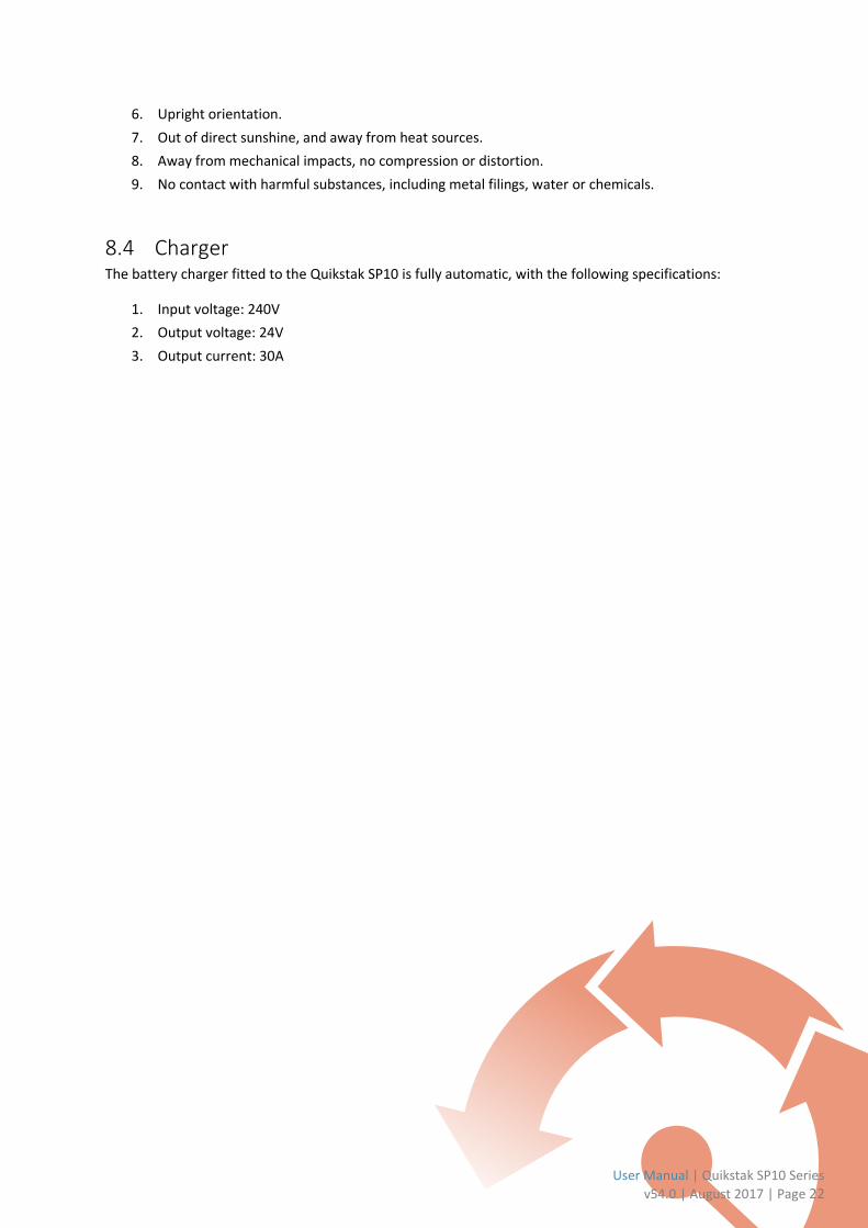
11.3 Monthly scheduled inspection The following inspection should be carried out monthly, or every 200 hours of use, whichever comes first.
Monthly Inspection Checklist
Category No. Item Check
Overall 1 Entire stacker
Check that the lifting, lowering, forward, reverse, and emergency reverse functions of the stacker operate correctly. No abnormal operation or noises.
Braking System
2 Control tiller While the tiller is pivoted up and down (between zones A and B), an audible clicking noise is emitted from the brake.
3 Friction plates Clean dirt and dust off friction plates. Check wear status and replace if necessary.
4 Brake clearance Ensure brake clearance is between 0.2mm and 0.5mm, using procedure in section 11.5.
Steering system
5 Control tiller Smooth unimpeded movement in all directions.
Structure
6 Frame and fastenings Visually inspect the frame for cracks, deformation or stress indicators. Apply lubrication as necessary and tighten fasteners.
7 Connecting rod and wheel carrier
Visually inspect the frame for cracks, deformation or stress indicators. Apply lubrication as necessary.
Hydraulic system
8 Hydraulic fluid Move the forks to the lowest position and check the reservoir contains 12 litres of fluid.
9 Oil lines No leaks.
10 Hydraulic ram No leaks.
Wheels 11 Pins, screws and fasteners
Check all the fasteners of the stacker’s wheels, i.e. pins or screws. Tighten if necessary.
12 Tyre wear Compare with standard parameters, replace wheel if diameter is reduced by more than 5%.
Electrical system and batteries
13 Charging plug Undamaged and fully functional.
14 Key switch Undamaged and fully functional.
15 Battery contactors Check battery contactors, roughen contact surfaces with sandpaper if necessary.
16 Leads The power leads are firmly connected.
17 Inching switch Undamaged and fully functional.
18 Controller Undamaged and fully functional.
21 Driving, lifting and steering motors
Undamaged and fully functional. Check wear status of carbon brushes and selenium rectifiers. Request service if necessary.
22 Fuses All intact.
23 Wiring harness and connection terminal
Undamaged and fully functional.
24 Horn Check that the horn sounds normally.
Instruments 25 Instrument function Turn the key switch to the ‘on’ position and check that all instruments display normally.

11.4 Biannual scheduled inspection Every six months, or 1200 hours of use, whichever comes first, the following items should be attended to
in addition to the normal monthly inspection.
Biannual Inspection Checklist
Category No. Item Check
Gearbox 1 Gearbox Replace the gear oil
Hydraulic system
2 Oil Filter Remove and clean the oil filter.
3 Hydraulic oil Replace the hydraulic oil.
4 Hydraulic ram Check for leakage. Replace seals if necessary.
Fork-guide wheels
5 Fork-guide wheels and bearings
Inspect wear status. Replace bearings if necessary.
11.5 Brake clearance adjustment procedure The structure of brake is
illustrated in Fig. 3. Over time
the brake performance will
decline due to wear and tear
on the friction plate. It is
periodically necessary to
adjust the clearance of the
brake pads, to maintain
responsive braking.
1. Clean the dirt and
dust off the brake
housing and friction
plates.
2. Using an insert
micrometer, measure
the clearance between the friction plate and the magnetic steel as shown in Fig. 3. If the
clearance is larger than 0.5mm, the brake should be adjusted.
3. If adjustment is necessary, first loosen the three fitting screws (2).
4. Carefully adjust the fitting screws (2) until the measured clearance is between 0.2mm-0.25mm,
and is evenly distributed around the brake.
5. The brake can now be tested with 24v DC power. If properly adjusted it will make a clear, sharp
‘click’ sound when activated.
Figure 3

User Manual | Quikstak SP10 Series
v54.0 | August 2017 | Page 28
11.6 Recommended lubricants
11.6.1 Hydraulic oil 1. Light-duty operations: HLPISOVG32, in accordance with standard DIN51524T.2. The average
sustained temperature is below 60 degrees.
2. Medium-duty operations: LHPISOVG46, in accordance with standard DIN51524T.2. The average
sustained temperature should between 40 degrees to 60 degrees.
3. Heavy-duty operations: LHPISOVG68, in accordance with standard DIN51524T.2. The average
sustained temperature is above 60 degrees.
4. Variable-duty operations: LHPISOVG46 in accordance with standard DIN51524T.2. This oil has
very high viscidity and can be used in all the above working conditions. This is the most
commonly-used hydraulic oil.
If the correct hydraulic oil is difficult to obtain, SAE20W/20 engine oil can be safely used as a
substitute for HLP68 hydraulic oil.
11.6.2 Gear oil Hyperbola gear oil 85W-90(GL-5).
11.6.3 Lubricating grease Type 3 lithium grease.
Waste oils and lubricants are extremely harmful to the environment, and should always be
recycled or properly disposed of in accordance with local regulations.
11.7 Consumables and Replacement Periods
Consumable Period Action Notes
Fork-guide wheel bearings 1200 hours Replace
Fork-guide wheel 1200 hours Replace
Hydraulic ram seals 1200 hours Replace Check wear. Replace only if necessary.
Gearbox lubricant grease 1000 hours Replace
Hydraulic oil 1000 hours Replace
High-pressure oil lines 2000 hours Replace Check wear. Replace only if necessary.
Hydraulic oil filter 1000 hours Clean
Drive motor 1000 hours Replace Check wear. Replace only if necessary.
Steering motor 1000 hours Replace Check wear. Replace only if necessary.
Lifting motor 1000 hours Replace Check wear. Replace only if necessary.

12 Storage, Loading and Transportation
12.1 Storage If the stacker is not to be used for a period of two months or more, it should be stored in a clean, dry
place with good ventilation, at temperatures not below 0℃. Before storing the stacker, the following
measures should also be taken:
1. Clean the stacker thoroughly.
2. Raise and lower the forks completely several times.
3. Move the forks to the lowest position.
4. If possible, raise the stacker slightly and place on wooden blocks adjacent to the drive wheel, to
prevent it from bearing the weight of the stacker while in storage.
5. Lubricate the stacker, and protect exposed surfaces of moving parts with a layer of oil or grease.
6. Check the battery and apply a non-acidic grease to the battery binding post.
7. Apply a small amount of suitable contact oil to all electrical contacts.
12.2 Lifting, loading and unloading The following precautions should always be taken when lifting, loading or unloading the stacker.
1. Confirm the weight of the stacker on the specification plate, and ensure the lifting equipment
that is to be used has sufficient capacity.
2. Use one person to operate the lifting equipment, and at least one other person to watch for
hazards and hold the stacker steady while it is being lifted.
3. Never stand or reach underneath the stacker while it is being lifted.
4. If a crane is being used, ensure it is securely fastened to the designated lifting eyes at the top of
the mast.
5. If another stacker is being used, ensure the forks are inserted in a suitable position beneath the
stacker. The weight should be transferred onto structural frame elements, and stacker should be
stable when lifted. Incorrect fork placement can damage the wheels or covers.
6. Lift, move and lower the stacker into place slowly and carefully. Ensure the stacker remains fully
upright throughout the lift.
Standard SP10 models weigh between 420kg and 500kg.
12.3 Transportation When the stacker is to be transported long distances, carry out the following procedure:
1. If the duration of transport is likely to be more than one week, raise the stacker slightly and place
on wooden blocks adjacent to the drive wheel, to prevent it from bearing the weight of the
stacker during transport.

User Manual | Quikstak SP10 Series
v54.0 | August 2017 | Page 30
2. Apply chocks to the outrigger wheels.
3. Tie the stacker down with strops rated for at least 1000kg.
Ensure the stacker is securely fastened against lateral forces from any direction.

13 Troubleshooting Guide
No. Fault Possible cause Action
1 Stacker will not turn on, no power light.
Control circuit fuse is blown. Replace
Power switch damaged or in poor condition.
Repair or replace
Main circuit fuse is blown. Replace
Electric lock damaged or in poor connection.
Repair or replace
Power leads loose or disconnected. Tighten
2 Stacker turns on, but forks will not raise.
The electromagnetic brake has failed to deactivate and the stacker is in a braked condition.
Repair or replace
The drive motor carbon brushes are worn, or making bad contact.
Repair or replace
The drive motor magnet-exciting coil is broken, or bad contact at the wire end.
Repair or replace
Bad electric contact. Repair or replace
Malfunction on the MOSFET tube circuit board.
Repair or replace
3 The stacker will only move forward or backward.
The contactor is in poor connection or burnt out.
Repair or replace
Malfunction on the MOSFET tube circuit board.
Repair or replace
4 Drive motor will not stop. Contact failure in drive circuit. Press emergency stop immediately and replace the contact
5 The brake will not operate.
The erection bolt of the fine motion switch is loose or damaged.
Adjust or tighten the bolt or replace the fine motion switch
The connecting wires of the electro-magnet brake are loose or damaged
Repair the wires and tighten connections
The frictions plates are worn. Adjust the clearance (see section 12.5) or replace friction plates.
6 The steering is jammed The control tiller bearing is damaged. Replace the bearing
The control tiller bearing lacks lubricant or there is too much dust
Clean the bearing
7 Steering is difficult and/or noisy operation and/or drive motor is overloaded.
Foreign matter is jamming the wheel bearings
Clean or replace the bearings
The wheel bearing clearance is adjusted incorrectly
Adjust the clearance
The front wheel bearing is damaged. Replace the bearing
8 The forks will not raise.
Overload Reduce the load
The overload valve pressure is set too low
Adjust the overload valve pressure
Hydraulic ram leakages Replace the ram seals
Insufficient hydraulic oil Lower forks, check the reservoir contains 12 litres of hydraulic oil.

User Manual | Quikstak SP10 Series
v54.0 | August 2017 | Page 32
Insufficient battery charge Charge the battery
The control tiller is not horizontal or vertical, so lift motor is deactivated.
Improper operation – control tiller must be in correct position
Damaged oil pump (lift) motor Repair or replace
Damaged oil pump Repair or replace
Damaged lifting button Repair or replace
The electric lock is damaged or malfunctioning.
Repair or replace
9 The forks will not lower.
The internal mast has been deformed by overloading
Repair or replace
The external mast has been deformed by overloading
Repair or replace
Failed or jammed mast roller Repair or adjust
Mast guide rod is deformed Repair or straighten
The oil return valve is blocked Clean valve
The oil return valve is damaged or malfunctioning
Repair or replace
10 The battery will not hold charge.
Battery is damaged or malfunctioning Repair or replace
11 The stacker shakes while traveling.
①Drive wheel nuts loose or missing. Tighten or replace drive wheel nuts.
②Balance wheel is not on the same plane as drive wheel and outrigger wheels.
Adjust bolts on balance wheel to correct plane.
14 Common Spare Parts
No. Name Use position Specification Shipping Units Remarks
1 Key Key switch 2
2 Fuse Electric equipment 50A 1
3 Fuse Electric equipment 125A 1
4 Sealing ring Hydraulic ram UHS45 1
5 O type sealing ring Hydraulic ram 50X3.55 1
6 Composite ring Oil inlet on hydraulic ram D14 1
7 Dustproof ring Hydraulic ram DH40 1
8 O type sealing ring Hydraulic ram UHS40 1

15 Adjusting the Overload Valve
The overload valve is set at the factory and does not normally need to be adjusted. Should the valve for
some reason be set incorrectly, it must be adjusted by an authorized qualified technician in accordance
with the test methods stipulated in the JB/T3300 standard, and as per the following procedures:
Incorrectly adjusting the overload valve may damage the stacker and cause a serious health and
safety hazard.
The Quikstak SP10 is designed to operate with a hydraulic pressure of 15.5Mpa.
1. Disconnect the high-pressure oil line.
2. Connect a hydraulic pressure meter with a capacity of at least 20Mpa.
3. Turn on the stacker and press the raise button for several seconds to generate hydraulic
pressure.
4. The stacker is designed to operate with a hydraulic pressure of 15.5Mpa.
5. If the pressure is not at the correct level, loosen the locknut on the overload valve.
6. Turn the pressure adjusting screw clockwise to increase the system pressure, and counter-
clockwise to reduce the system pressure. Adjust the screw and repeat steps 3 and 4 until the
correct reading is reached.
7. Re-tighten the locknut.
Figure 4
User Manual | Quikstak SP10 Series
v54.0 | August 2017 | Page 34
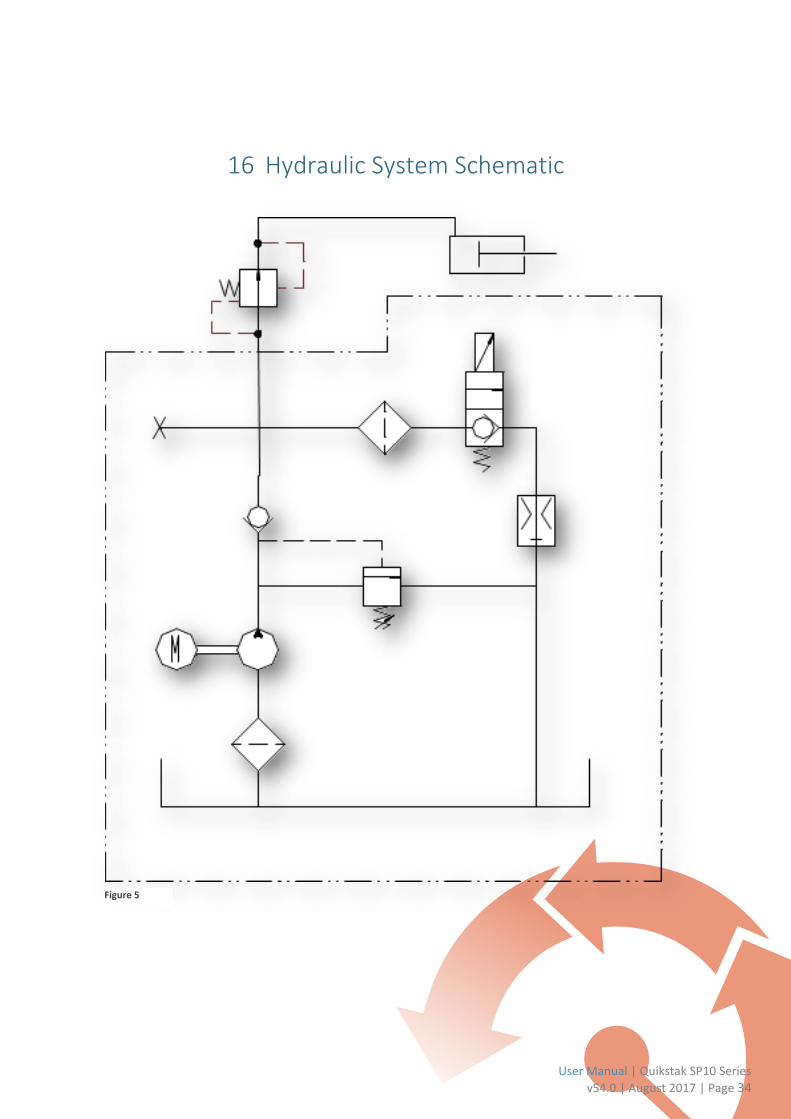
16 Hydraulic System Schematic
Figure 5

17 Electrical System Schematic
The Quikstak SP10 uses a Curtiss 1212 electronic controller.
Figure 6

User Manual | Quikstak SP10 Series
v54.0 | August 2017 | Page 36
18 Weekly Maintenance Log
The checks required for the weekly scheduled inspections are described in section 11.2.
Date/Time Service Person
Location Checks complete
Notes on repairs or maintenance required
Parts and materials used

19 Monthly Maintenance Log
The checks required for the monthly scheduled inspections are described in section 11.3.
Date/Time Service Person
Location Checks complete
Notes on repairs or maintenance required
Parts and materials used

User Manual | Quikstak SP10 Series
v54.0 | August 2017 | Page 38
20 Biannual Maintenance Log
The checks required for the biannual scheduled inspections are described in section 11.4.
Date/Time Service Person
Location Checks complete
Notes on repairs or maintenance required
Parts and materials used
