what's new in medium voltage drives -...
TRANSCRIPT
What's New In Medium Voltage Drives
William LockleyTechnical ConsultantTechnical ConsultantLockley Engineering
Richard PaesGlobal Industry Technical Consultant – Oil & Gas R k ll A t tiRockwell Automation
IEEE Northern Canada & Southern Alberta Sections PES/IAS Joint Chapter Technical Seminar
Outline
• Adjustable Speed Drive Basics• What is a “Drive”• Purpose and benefits of ASD• Typical Applications
• Adjustable Speed Drive DesignsAdjustable Speed Drive Designs• ASD Design Fundamentals – Semiconductors• Voltage / Current source• Rectifiers• Rectifiers
• Passive / Active Front End• Multi-pulse
• Inverters• Inverters• 2 Level• Multilevel• Series H bridge
Slide 2 / What's New with MV Drives & IEEE 1566 - IEEE SAS & NCS 2014
Series H bridge
Outline
• Adjustable Speed Drive Basics (continued)j ( )• Typical voltage source topologies• Typical current source topologies
• What’s New with MV Drives• New directions and focus
Industry Trends• Industry Trends• Specialized Applications• New Frontiers
Slide 3 / What's New with MV Drives & IEEE 1566 - IEEE SAS & NCS 2014

Outline
IEEE 1566 L D i St d d• IEEE 1566 Large Drive Standard
• Adjustable Speed Drive System (ASDS)• Adjustable Speed Drive History• Purpose and need for the standard • Status of the standard• IEEE 1566 2nd Edition• Technical changes and innovations• Overview• Unique applications such as marine, long cable runs and generator
supply• Data Sheet and Data Sheet Guide• How to apply and order a MV ASD
• Conclusion
Slide 4 / What's New with MV Drives & IEEE 1566 - IEEE SAS & NCS 2014
Conclusion
What is a “Drive”?
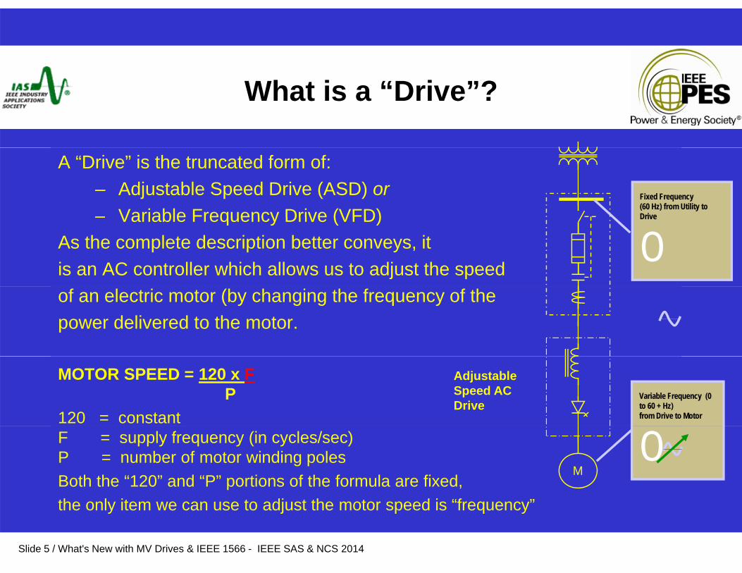
A “Drive” is the truncated form of:– Adjustable Speed Drive (ASD) or– Variable Frequency Drive (VFD)
Fixed Frequency (60 Hz) from Utility to Drive– Variable Frequency Drive (VFD)
As the complete description better conveys, it is an AC controller which allows us to adjust the speed
Drive
Oof an electric motor (by changing the frequency of the power delivered to the motor.
MOTOR SPEED = 120 x FP
120 = constant
Adjustable Speed AC Drive
Variable Frequency (0 to 60 + Hz) from Drive to Motor
F = supply frequency (in cycles/sec)P = number of motor winding polesBoth the “120” and “P” portions of the formula are fixed,
MO
Slide 5 / What's New with MV Drives & IEEE 1566 - IEEE SAS & NCS 2014
the only item we can use to adjust the motor speed is “frequency”
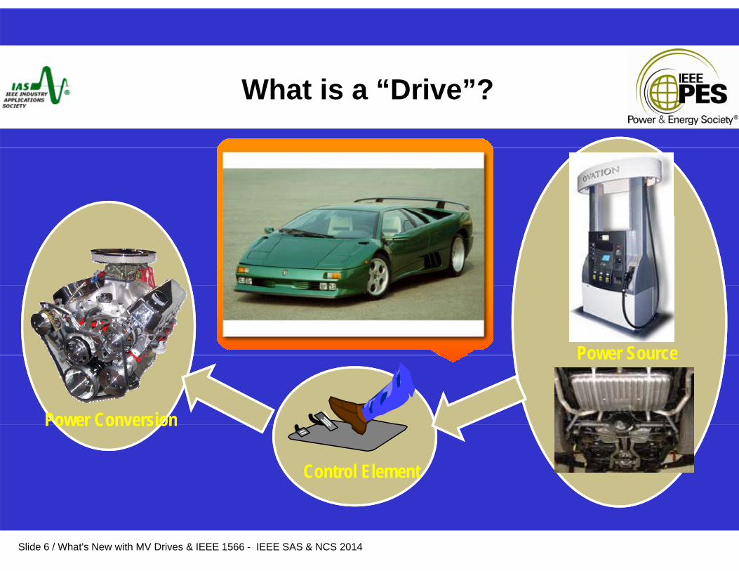
What is a “Drive”?
Power SourcePower Source
Power Conversion
Control Element
Power Conversion
Slide 6 / What's New with MV Drives & IEEE 1566 - IEEE SAS & NCS 2014

Medium Voltage Drive
rectifier dc link inverterAC motorAC supply
MV drive
Voltage Range
rectifier dc link inverter
Voltage Range
Power Range
1kV 3.3 kV
4.16
kV
6.6 kV
11 kV 15 kV2.3 kV
35 MW
Power Range
0 2 8 MW1 MW 4 MW2 MW 12 MW0 5
Slide 7 / What's New with MV Drives & IEEE 1566 - IEEE SAS & NCS 2014
0.2 MW
8 MW1 MW 4 MW2 MW 12 MW0.5 MW
Why Use Adjustable Speed Drives ?
BASICSBASICS
• Match the speed of the drive / motor to the process requirementsMatch the speed of the drive / motor to the process requirements
• Match the torque of the drive / torque to the process requirements
• Energy Savings
Slide 8 / What's New with MV Drives & IEEE 1566 - IEEE SAS & NCS 2014

Why Use Adjustable Speed Drives ?
•Reduce maximum utility demand – electrical and cost•Meet utility flicker restrictions while starting large loads•Improve equipment life due to soft starting•Increase mechanical equipment life by running at slower speeds•Controlled application of torque
i.e. reduced water hammer effectsi e conveyorsi.e. conveyors
•Reduced Pump Cavitation Problems•Reduce preventative and corrective maintenance costs by eliminating complex mechanical equipment – valves, dampers, etc.•Allows the use of standard induction motors while increasing performance in terms of torque, inrush and power factor• Reduce motor stress - transient torques, thermal heating at start condition, no limit of starts/hr, high inertia loadsinertia loads•Improve process control by ‘infinite’ speed control and better information / tie in with supervisory control system•Forward / Reverse operation•Regenerative braking
Slide 9 / What's New with MV Drives & IEEE 1566 - IEEE SAS & NCS 2014
Regenerative braking
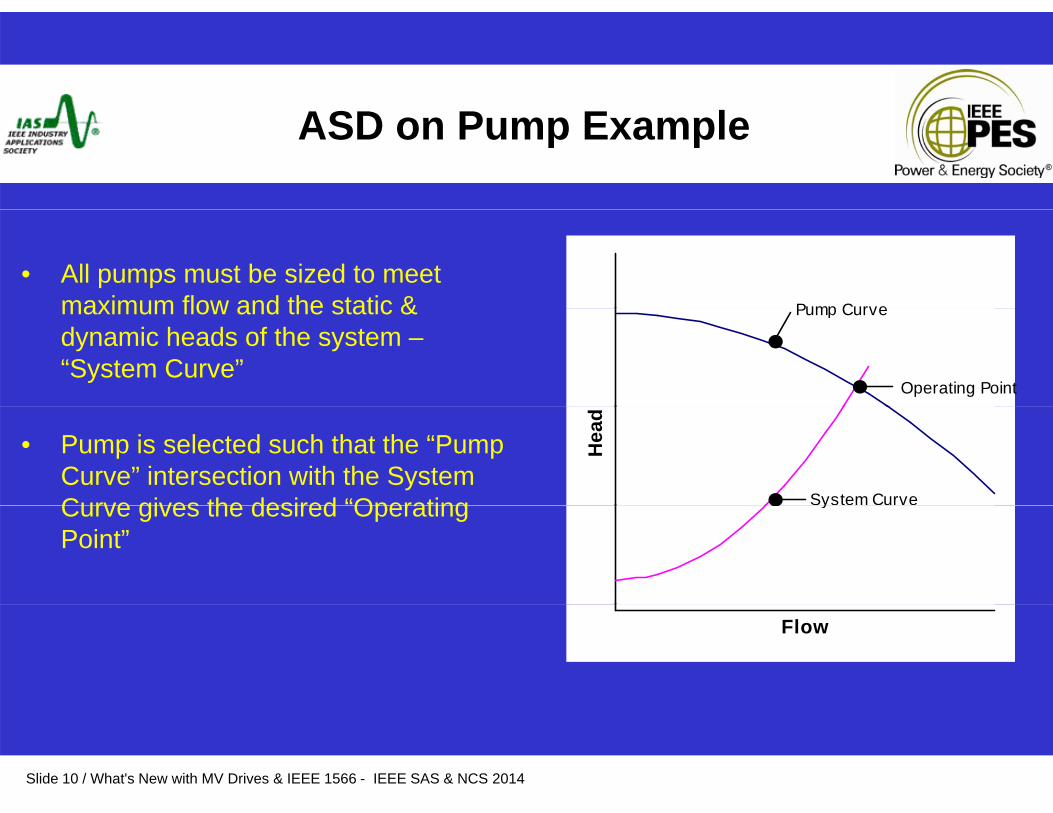
ASD P E lASD on Pump Example
• All pumps must be sized to meet maximum flow and the static & Pump Curvemaximum flow and the static & dynamic heads of the system –“System Curve”
Pump Curve
Operating Point
• Pump is selected such that the “Pump Curve” intersection with the System Curve gives the desired “Operating
Hea
d
System CurveCurve gives the desired Operating Point”
y
Flow
Slide 10 / What's New with MV Drives & IEEE 1566 - IEEE SAS & NCS 2014

Pump Operating characteristics
• Without the use of an ASD, the flow must be controlled with the use ofcontrolled with the use of a valve which drops pressure across it
Pump speed curves & system curves
valve control
system curve
• Pressure drop = Losses
sure
decrease in pressure
Increase in pressure withvalve throttling
system curve
Pre p
with AFD use
1200rpm
Flow
reduced flow 1000rpm
Slide 11 / What's New with MV Drives & IEEE 1566 - IEEE SAS & NCS 2014
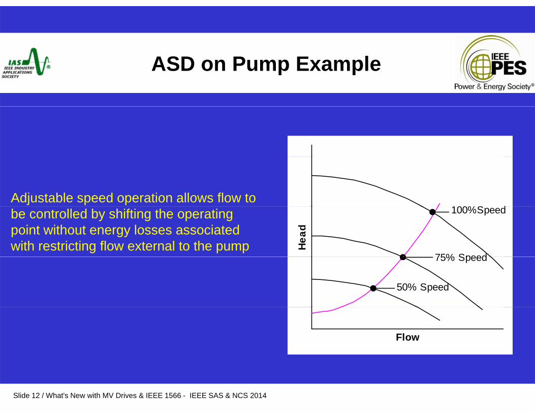
ASD P E lASD on Pump Example
Adjustable speed operation allows flow to 100%S dbe controlled by shifting the operating
point without energy losses associated with restricting flow external to the pump He
ad
100%Speed
75% Speed75% Speed
50% Speed
Flow
Slide 12 / What's New with MV Drives & IEEE 1566 - IEEE SAS & NCS 2014
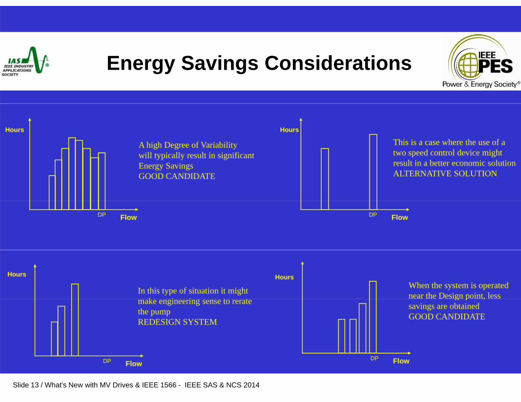
Energy Savings Considerations
Hours
A high Degree of Variabilityill i ll l i i ifi
Hours
This is a case where the use of atwo speed control device mightwill typically result in significant
Energy Savings GOOD CANDIDATE
two speed control device might result in a better economic solutionALTERNATIVE SOLUTION
FlowDP FlowDP
In this type of situation it mightk i i t t
Hours
When the system is operated near the Design point, less
Hours
make engineering sense to rerate the pumpREDESIGN SYSTEM
g p ,savings are obtainedGOOD CANDIDATE
Slide 13 / What's New with MV Drives & IEEE 1566 - IEEE SAS & NCS 2014
FlowDP FlowDP
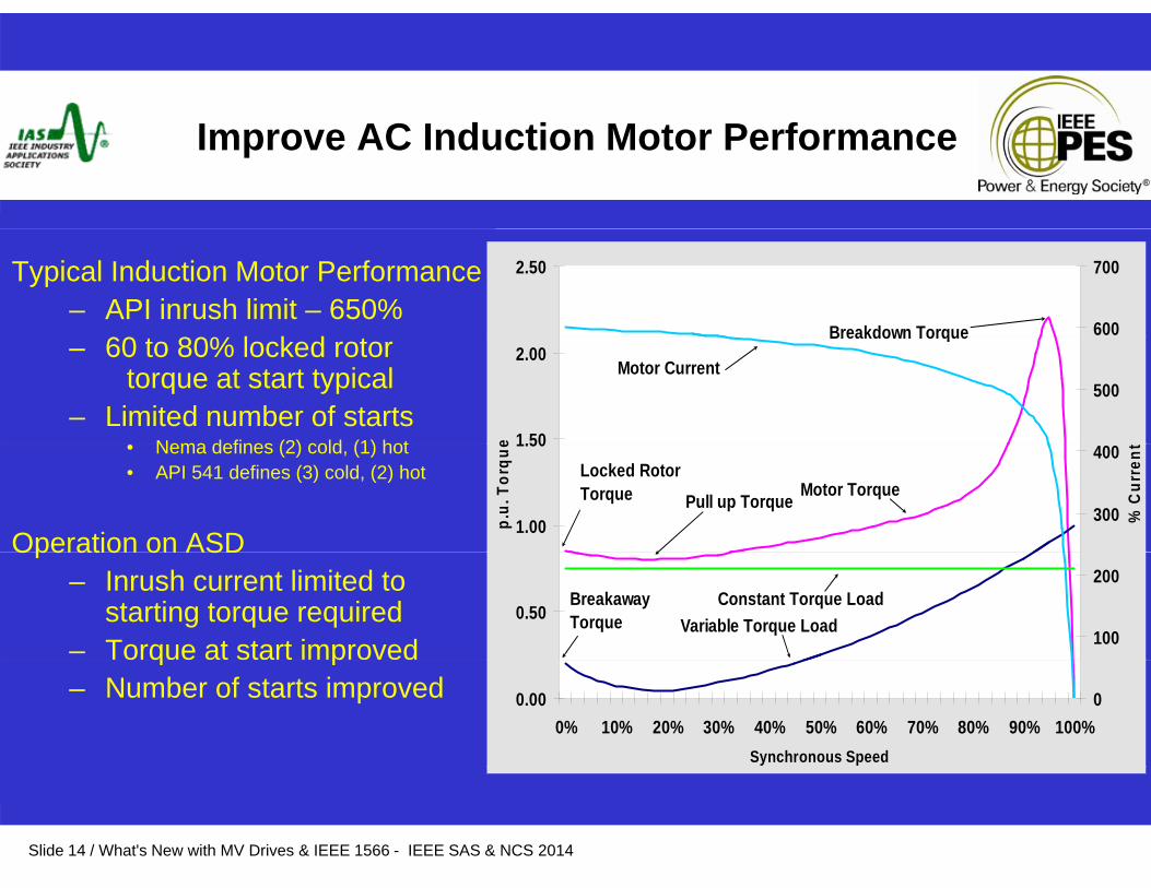
Improve AC Induction Motor Performance
Typical Induction Motor Performance – API inrush limit – 650%
60 80% l k d
2.50
600
700
Breakdown Torque– 60 to 80% locked rotor torque at start typical
– Limited number of startsNema defines (2) cold (1) hot 1.50
2.00
e
500
Breakdown Torque
Motor Current
• Nema defines (2) cold, (1) hot• API 541 defines (3) cold, (2) hot
Operation on ASD1.00
1.50
p.u.
Tor
que
300
400
% C
urre
nt
Pull up TorqueLocked Rotor Torque Motor Torque
Operation on ASD – Inrush current limited to
starting torque required– Torque at start improved
0.50100
200Breakaway Torque Variable Torque Load
Constant Torque Load
q p– Number of starts improved 0.00
0% 10% 20% 30% 40% 50% 60% 70% 80% 90% 100%Synchronous Speed
0
Slide 14 / What's New with MV Drives & IEEE 1566 - IEEE SAS & NCS 2014
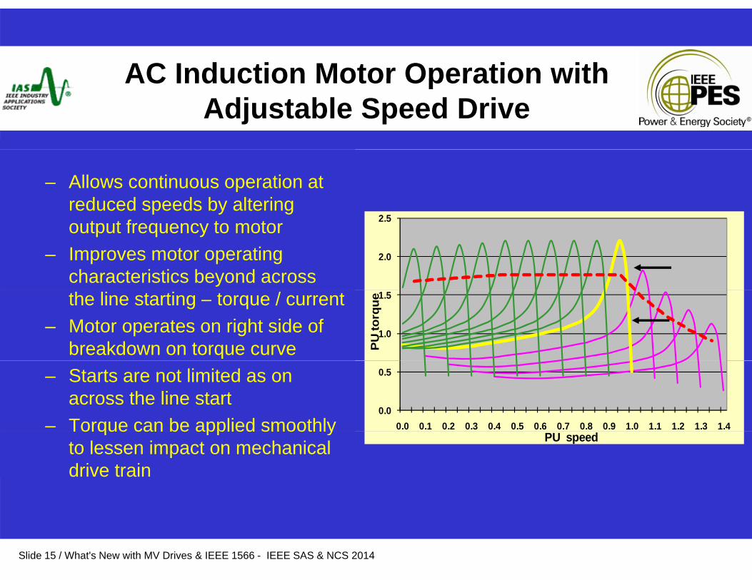
AC Induction Motor Operation withAC Induction Motor Operation with Adjustable Speed Drive
– Allows continuous operation at reduced speeds by altering
f 2 5output frequency to motor– Improves motor operating
characteristics beyond across 2.0
2.5
the line starting – torque / current– Motor operates on right side of
breakdown on torque curve 1.0
1.5
PU
torq
ue– Starts are not limited as on
across the line start– Torque can be applied smoothly
0.0
0.5
0.0 0.1 0.2 0.3 0.4 0.5 0.6 0.7 0.8 0.9 1.0 1.1 1.2 1.3 1.4Torque can be applied smoothly to lessen impact on mechanical drive train
PU speed
Slide 15 / What's New with MV Drives & IEEE 1566 - IEEE SAS & NCS 2014
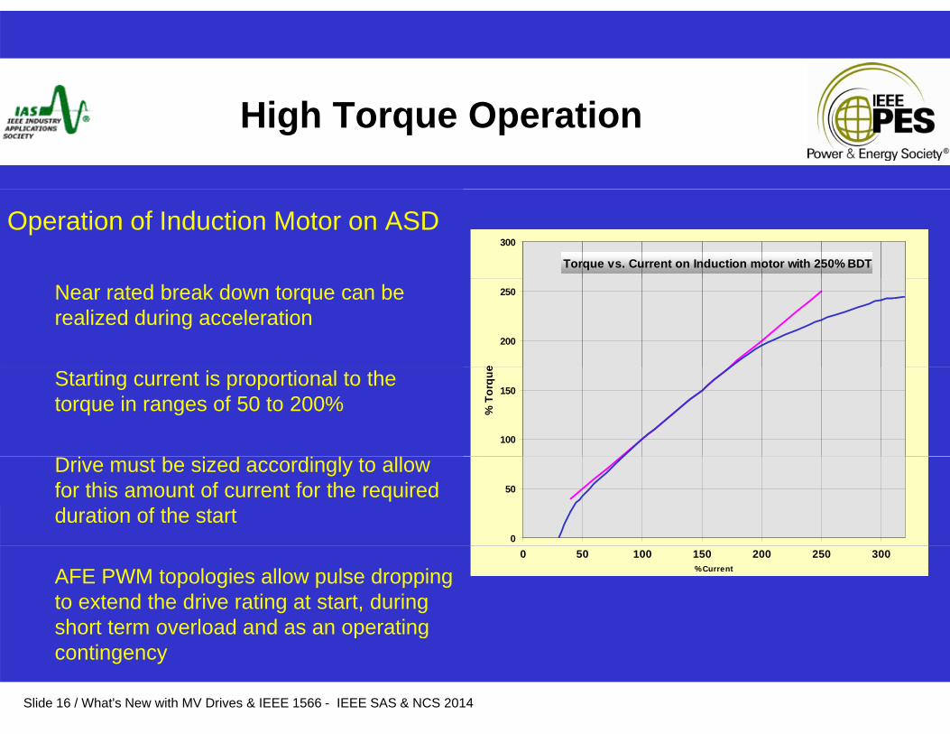
High Torque Operation
Operation of Induction Motor on ASDTorque vs. Current on Induction motor with 250% BDT
300
Near rated break down torque can be realized during acceleration
200
250
e
Starting current is proportional to the torque in ranges of 50 to 200%
100
150
% T
orqu
e
Drive must be sized accordingly to allow for this amount of current for the required duration of the start
0
50
AFE PWM topologies allow pulse dropping to extend the drive rating at start, during short term overload and as an operating
0 50 100 150 200 250 300% Current
Slide 16 / What's New with MV Drives & IEEE 1566 - IEEE SAS & NCS 2014
p gcontingency
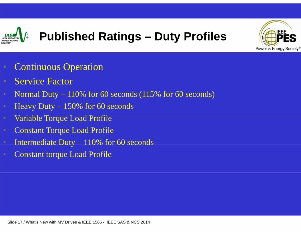
Published Ratings – Duty Profiles
• Continuous Operation• Service Factor• Normal Duty – 110% for 60 seconds (115% for 60 seconds)• Heavy Duty – 150% for 60 seconds
V i bl T L d P fil• Variable Torque Load Profile• Constant Torque Load Profile• Intermediate Duty – 110% for 60 secondsIntermediate Duty 110% for 60 seconds• Constant torque Load Profile
Slide 17 / What's New with MV Drives & IEEE 1566 - IEEE SAS & NCS 2014

Load Requirements160
Load Profile is the prime consideration when sizing an ASD
Continuous operationSt ti
Variable torque profiles, 60Hz
100
110
120
130
140
150
HP Variable Torque Load %Starting
Motoring• Motor Rating – FLC particularly 30
40
50
60
70
80
90
% T
orqu
e &
H Variable Torque Load %
HP at variable torque %
ND Drive continuous torque
Motor Rating FLC particularly• Starting Overload• Continuous Operation
– Ambient / Environmental Conditions
0
10
20
0 5 10 15 20 25 30 35 40 45 50 55 60 65 70 75Frequency
150 0
160.0
– Load type – variable / constant torque
– Service FactorC li L di / O l di
Constant Torque Profiles, 60Hz
90.0
100.0
110.0
120.0
130.0
140.0
150.0
e &
HP
• Cyclic Loading / Overloading
Braking • Overhauling load 20.0
30.0
40.0
50.0
60.0
70.0
80.0
% T
orqu
Constant Torque Load %
HP at constant torque %
HD Drive continuous torque
Slide 18 / What's New with MV Drives & IEEE 1566 - IEEE SAS & NCS 201418
O g• Similar aspects to the above 0.0
10.0
0 5 10 15 20 25 30 35 40 45 50 55 60 65 70 75Frequency
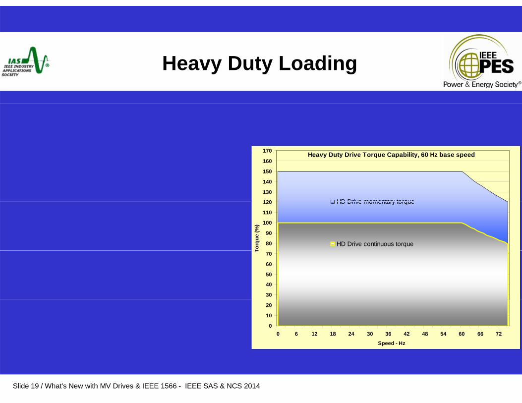
Heavy Duty Loading
H D t D i T C bilit 60 H b d170 Heavy Duty Drive Torque Capability, 60 Hz base speed
120
130
140
150
160
HD Drive momentary torque
80
90
100
110
120
Torq
ue (%
)
HD Drive momentary torque
HD Drive continuous torque
30
40
50
60
70T
0
10
20
0 6 12 18 24 30 36 42 48 54 60 66 72
Speed - Hz
Slide 19 / What's New with MV Drives & IEEE 1566 - IEEE SAS & NCS 2014
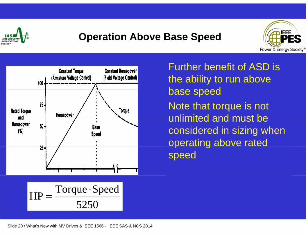
Operation Above Base Speed
Further benefit of ASD is the ability to run above base speedbase speedNote that torque is not unlimited and must beunlimited and must be considered in sizing when operating above rated p gspeed
5250SpeedTorqueHP ⋅=
Slide 20 / What's New with MV Drives & IEEE 1566 - IEEE SAS & NCS 2014
5250
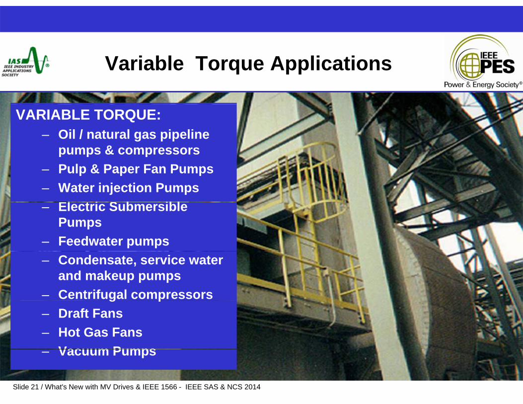
Variable Torque Applications
VARIABLE TORQUE:– Oil / natural gas pipeline
pumps & compressorspumps & compressors– Pulp & Paper Fan Pumps – Water injection Pumps
El t i S b ibl– Electric Submersible Pumps
– Feedwater pumps– Condensate, service water
and makeup pumps – Centrifugal compressorsg p– Draft Fans– Hot Gas Fans
Vacuum Pumps
Slide 21 / What's New with MV Drives & IEEE 1566 - IEEE SAS & NCS 2014
– Vacuum Pumps
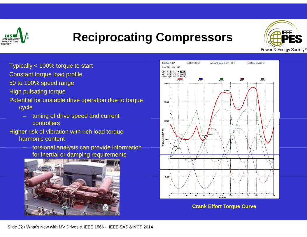
Reciprocating Compressors
Typically < 100% torque to startConstant torque load profile50 to 100% speed rangeHi h l ti tHigh pulsating torquePotential for unstable drive operation due to torque
cycle– tuning of drive speed and current g p
controllersHigher risk of vibration with rich load torque
harmonic contenttorsional analysis can provide information– torsional analysis can provide information for inertial or damping requirements
C k Eff t T C
Slide 22 / What's New with MV Drives & IEEE 1566 - IEEE SAS & NCS 2014
Crank Effort Torque Curve

Positive Displacement Pumps
Crank angle shows Pulsation of load torque over 1 rev of pumpload torque over 1 rev of pump shaft revolution
Peak at 100 degrees = 6138 NmMin at Separation of 120 degreesMin at Separation of 120 degrees
= 3906 NmTorque r.m.s. = 5073 NmTorsional vibration study may help
in determining coupling, flywheel and torsional damping
i trequirements
Slide 23 / What's New with MV Drives & IEEE 1566 - IEEE SAS & NCS 2014

Apron Feeder / Conveyor Applications
Constant torque applicationRated torque is required over 0 -100% speedShort term 150% start torque is typical but torque levels and duration q yp qrequirements vary with each applicationHigher / custom starting torques can be accommodatedDifferent dynamics and control requirements are encountered depending onDifferent dynamics and control requirements are encountered depending on conveyor configuration• Uphill, downhill, level or combination of these• Different lengths, tension control systems Speed / Torque Reference communications
Control System
Tension or Speed Feedback signals
• Single or multi-motor• Drive pulley arrangement
Affected parametersSt ti t
VFD VFDVFD
Master SlaveSlave
Motor
Reducer
Motor
Reducer
Motor
Reducer
• Starting torque• Regenerative Braking• Load-sharing• Brake interface SlaveSlave
Reducer ReducerTake up roll system
Slide 24 / What's New with MV Drives & IEEE 1566 - IEEE SAS & NCS 201424
VFD VFD
SlaveSlaveMotor Motor
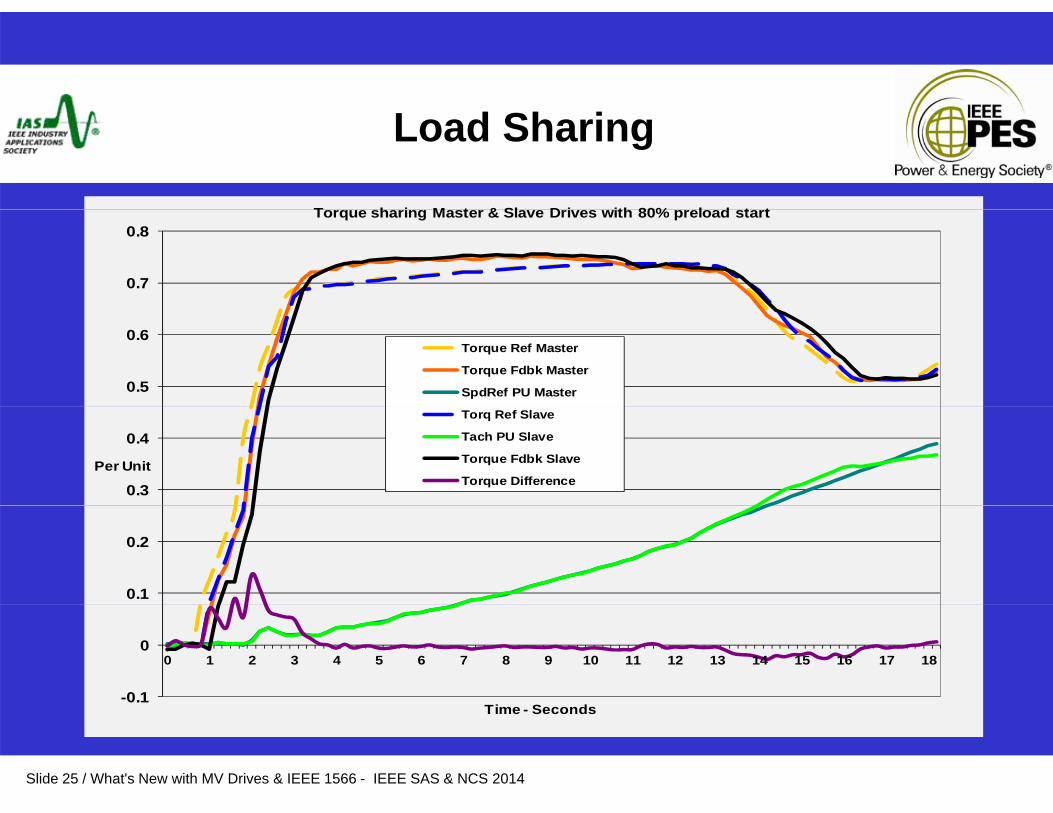
Load Sharing
T h i M t & Sl D i ith 80% l d t t
0.7
0.8Torque sharing Master & Slave Drives with 80% preload start
0.5
0.6Torque Ref Master
Torque Fdbk Master
SpdRef PU Master
0.3
0.4
Per Unit
Torq Ref Slave
Tach PU Slave
Torque Fdbk Slave
Torque Difference
0.1
0.2
-0.1
00 1 2 3 4 5 6 7 8 9 10 11 12 13 14 15 16 17 18
Slide 25 / What's New with MV Drives & IEEE 1566 - IEEE SAS & NCS 2014
Time - Seconds
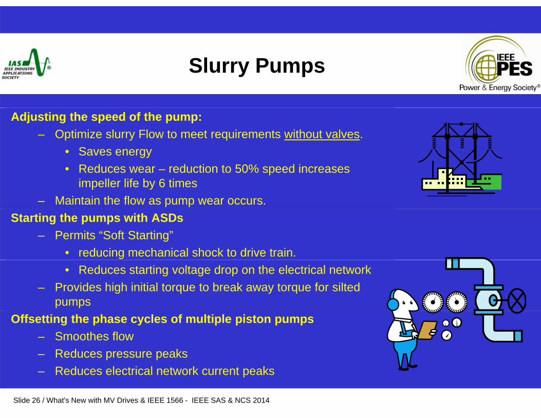
Slurry Pumps
Adjusting the speed of the pump: – Optimize slurry Flow to meet requirements without valves.
• Saves energy• Reduces wear – reduction to 50% speed increases
impeller life by 6 times– Maintain the flow as pump wear occurs.
Starting the pumps with ASDs– Permits “Soft Starting”
• reducing mechanical shock to drive train.• Reduces starting voltage drop on the electrical network
– Provides high initial torque to break away torque for silted pumps
Offsetting the phase cycles of multiple piston pumps– Smoothes flow– Reduces pressure peaks
Slide 26 / What's New with MV Drives & IEEE 1566 - IEEE SAS & NCS 2014
– Reduces electrical network current peaks
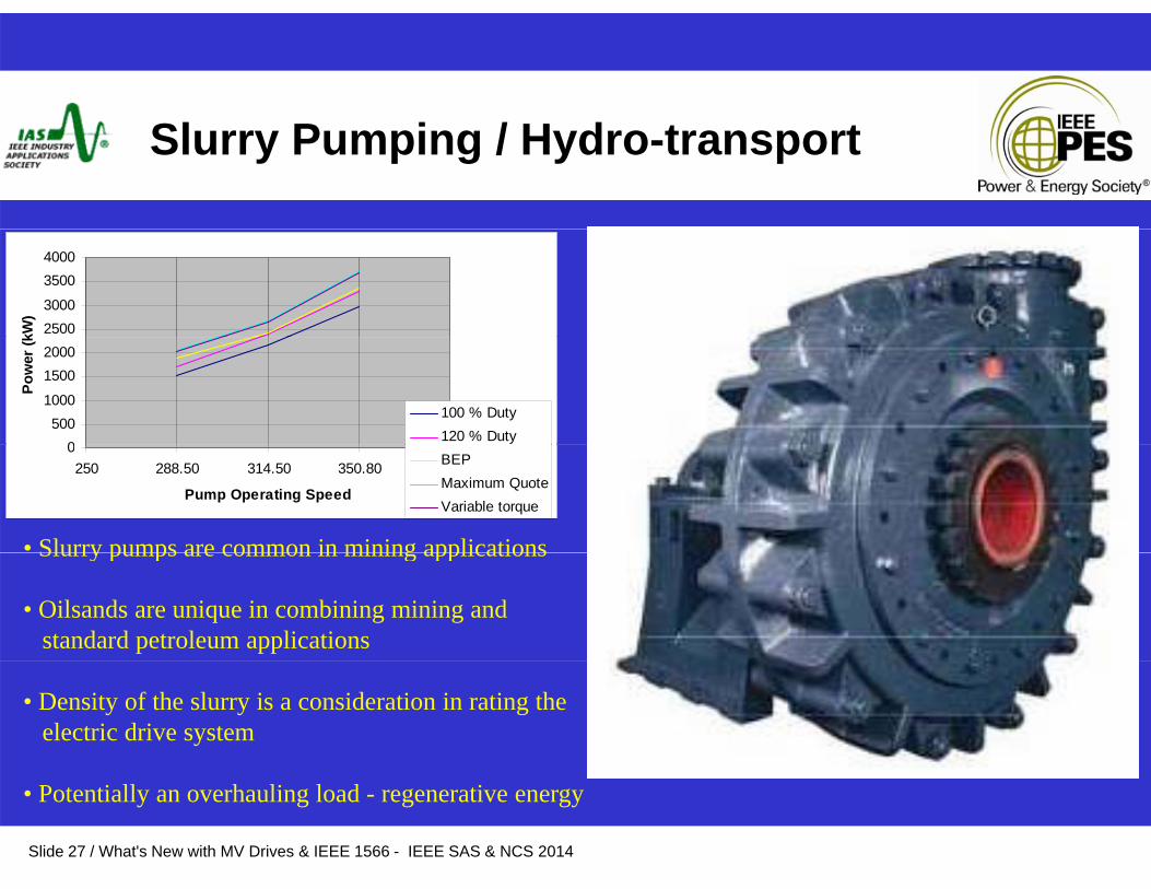
Slurry Pumping / Hydro-transport
25003000
35004000
kW)
0500
1000
15002000
Pow
er (k
100 % Duty120 % Duty
0250 288.50 314.50 350.80
Pump Operating Speed
BEPMaximum QuoteVariable torque
• Slurry pumps are common in mining applicationsSlurry pumps are common in mining applications
• Oilsands are unique in combining mining and standard petroleum applications
• Density of the slurry is a consideration in rating theelectric drive system
Slide 27 / What's New with MV Drives & IEEE 1566 - IEEE SAS & NCS 2014
• Potentially an overhauling load - regenerative energy
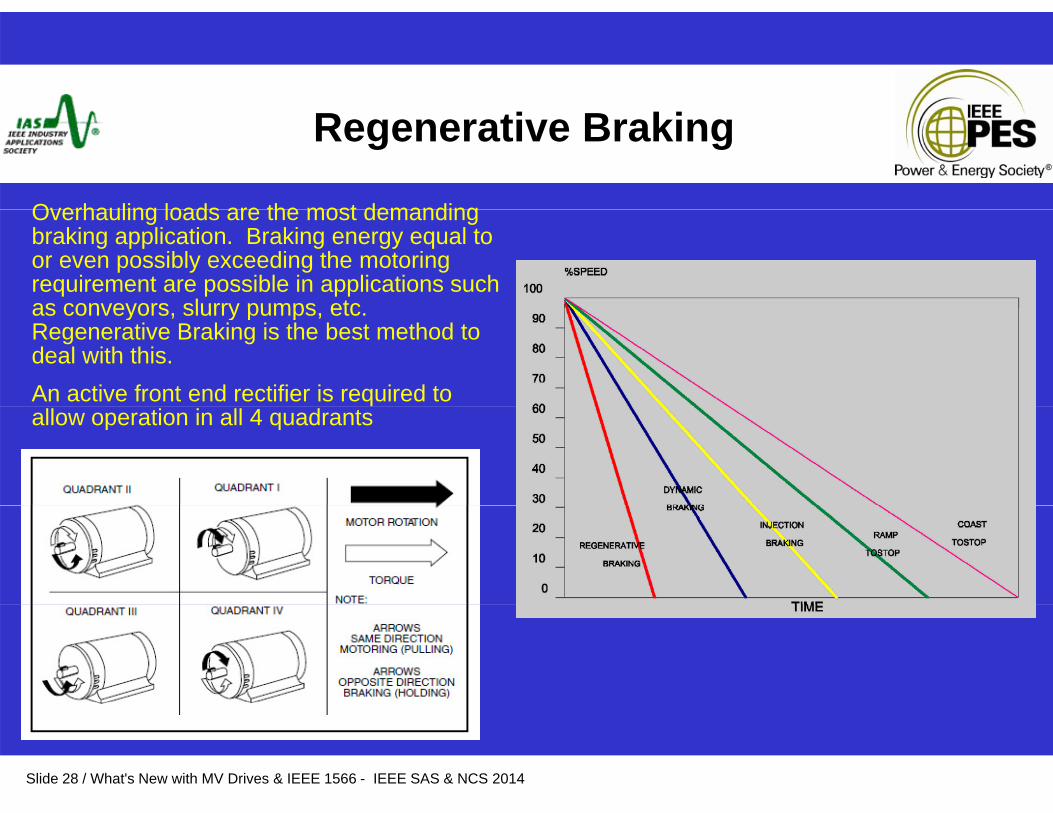
Regenerative Braking
Overhauling loads are the most demandingOverhauling loads are the most demanding braking application. Braking energy equal to or even possibly exceeding the motoring requirement are possible in applications such as conveyors slurry pumps etcas conveyors, slurry pumps, etc. Regenerative Braking is the best method to deal with this. An active front end rectifier is required to allow operation in all 4 quadrants
Slide 28 / What's New with MV Drives & IEEE 1566 - IEEE SAS & NCS 2014
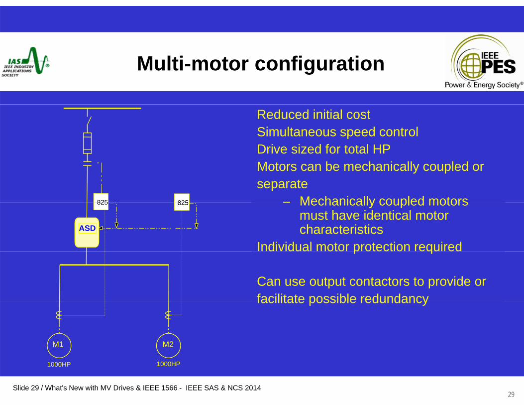
Multi-motor configuration
Reduced initial costSimultaneous speed controlDrive sized for total HPDrive sized for total HPMotors can be mechanically coupled or separate
– Mechanically coupled motors825825 Mechanically coupled motors must have identical motor characteristics
Individual motor protection required
825825
ASD
p q
Can use output contactors to provide or facilitate possible redundancyfacilitate possible redundancy
M2M1
Slide 29 / What's New with MV Drives & IEEE 1566 - IEEE SAS & NCS 201429
1000HP1000HP
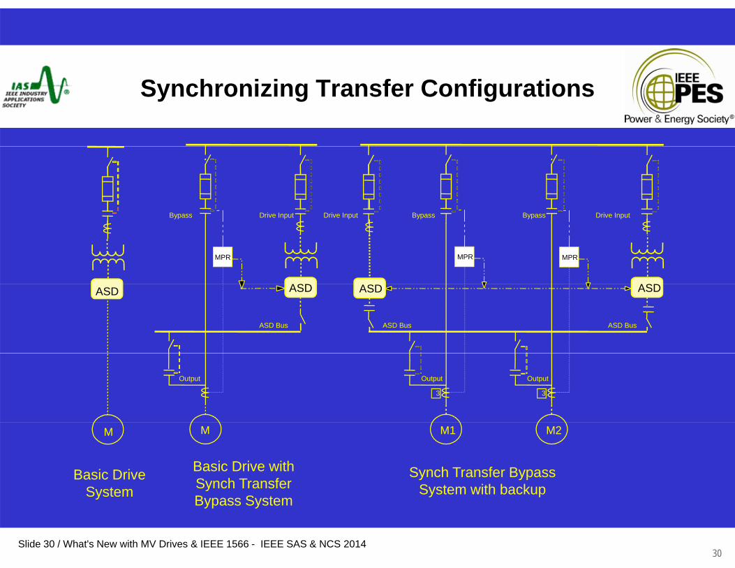
Synchronizing Transfer Configurations
BypassBypassBypass Drive Input Drive Input Drive InputBypass
MPR
Bypass
MPR
ASDS
Bypass
MPR
ASD
Drive Input Drive Input Drive Input
ASD Bus
ASD
ASD Bus
ASD
ASD Bus
ASDASD
3
Output
3
OutputOutput
M2M1MM
Basic DriveSystem
Basic Drive withSynch Transfer
Synch Transfer Bypass System with backup
Slide 30 / What's New with MV Drives & IEEE 1566 - IEEE SAS & NCS 201430
System yBypass System
System with backup
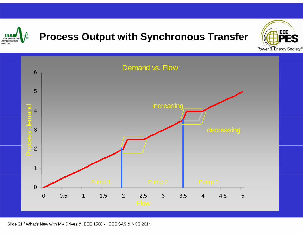
Process Output with Synchronous Transfer
Demand vs. Flow6
4
5
man
d increasing
3
cess
dem
decreasing
1
2
Pro
00 0.5 1 1.5 2 2.5 3 3.5 4 4.5 5
Flow
Pump 1 Pump 2 Pump 3
Slide 31 / What's New with MV Drives & IEEE 1566 - IEEE SAS & NCS 2014
Flow
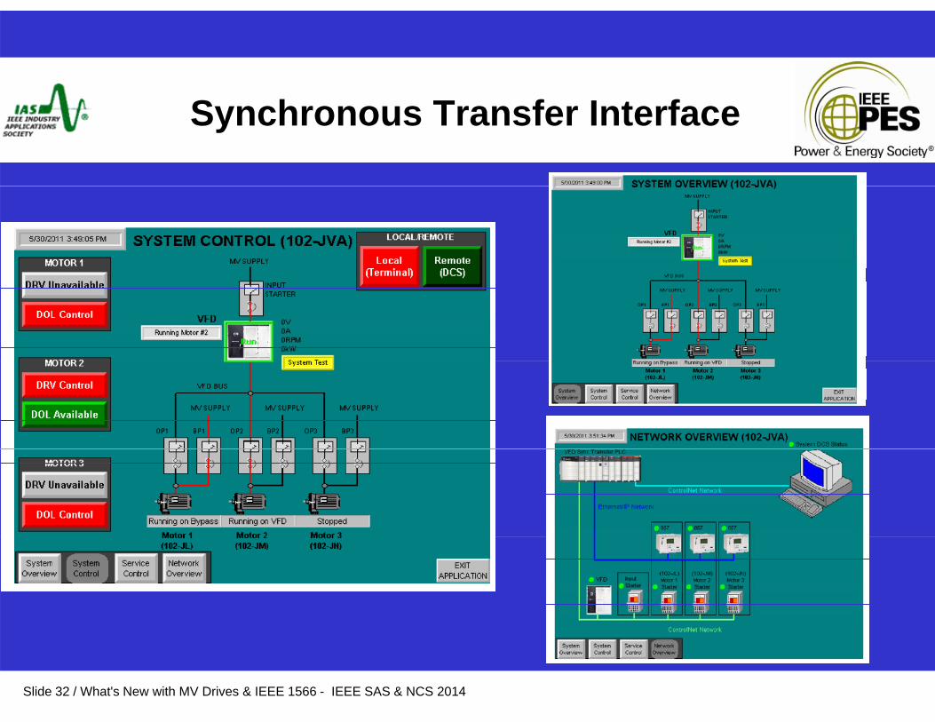
Synchronous Transfer Interface
Slide 32 / What's New with MV Drives & IEEE 1566 - IEEE SAS & NCS 2014
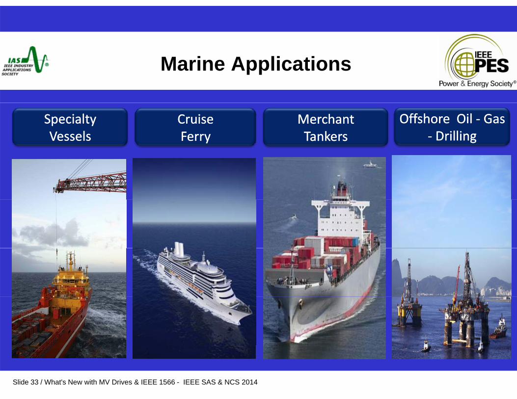
Marine Applications
Cruise Cruise Ferry Ferry
Merchant Merchant Tankers Tankers
Offshore Oil Offshore Oil -- Gas Gas -- Drilling Drilling
Specialty Specialty VesselsVessels
Slide 33 / What's New with MV Drives & IEEE 1566 - IEEE SAS & NCS 2014
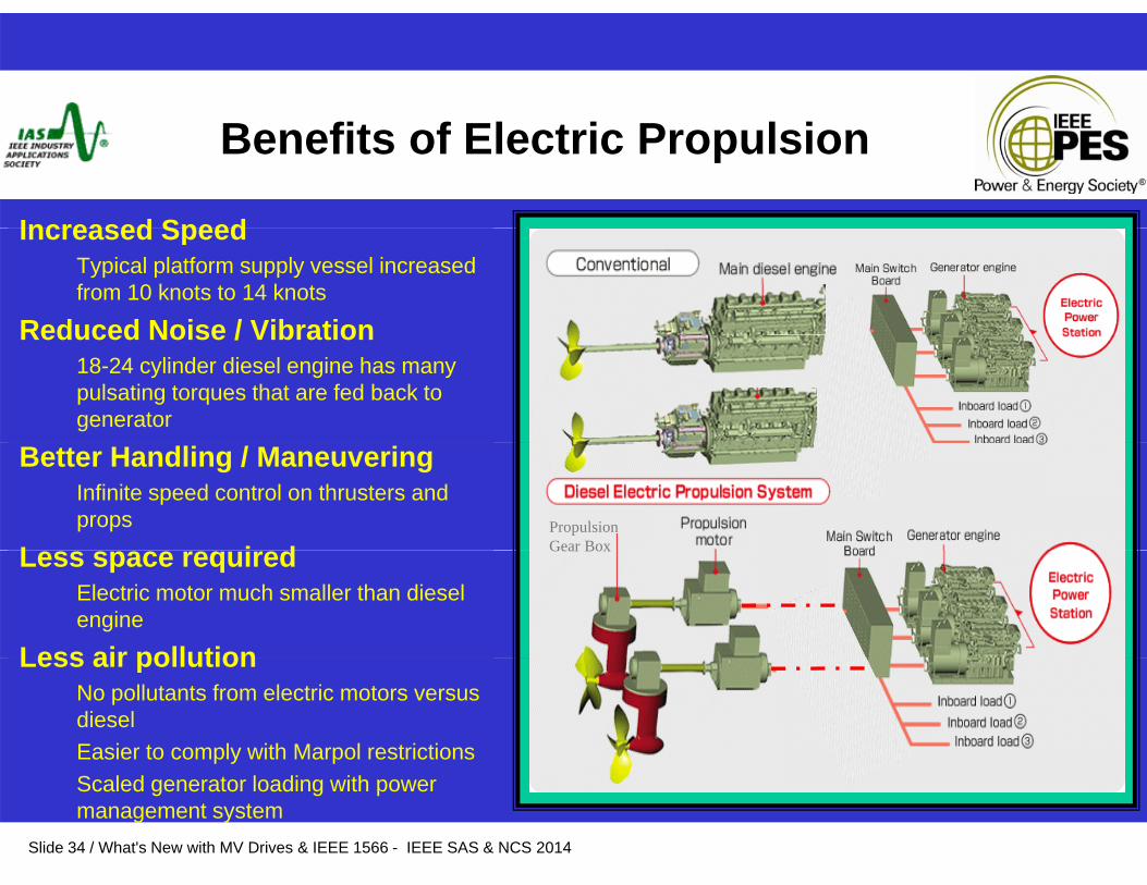
Benefits of Electric Propulsion
Increased SpeedIncreased SpeedTypical platform supply vessel increased from 10 knots to 14 knots
Reduced Noise / VibrationReduced Noise / Vibration18-24 cylinder diesel engine has many pulsating torques that are fed back to generator
Better Handling / ManeuveringInfinite speed control on thrusters and props
L i dPropulsion Gear BoxLess space required
Electric motor much smaller than diesel engine
Less air pollution
Gear Box
Less air pollutionNo pollutants from electric motors versus diesel Easier to comply with Marpol restrictions
Slide 34 / What's New with MV Drives & IEEE 1566 - IEEE SAS & NCS 2014
Scaled generator loading with power management system
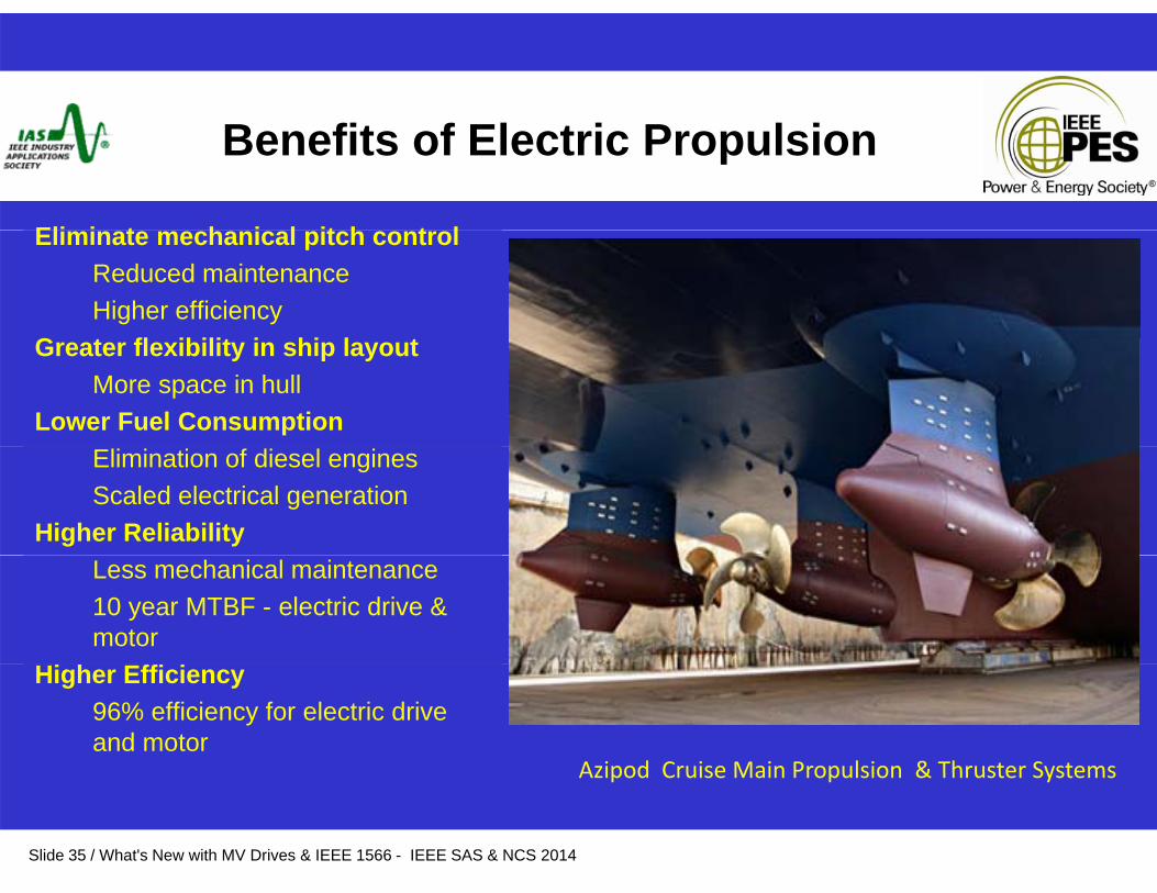
Benefits of Electric Propulsion
Eli i t h i l it h t lEliminate mechanical pitch control Reduced maintenanceHigher efficiency
G t fl ibilit i hi l tGreater flexibility in ship layoutMore space in hull
Lower Fuel ConsumptionElimination of diesel enginesScaled electrical generation
Higher ReliabilityLess mechanical maintenance10 year MTBF - electric drive & motor
Higher Efficiency96% efficiency for electric drive and motor
Azipod Cruise Main Propulsion & Thruster Systems
Slide 35 / What's New with MV Drives & IEEE 1566 - IEEE SAS & NCS 2014
Azipod Cruise Main Propulsion & Thruster Systems

Antarctic Research Vessel
Main Propulsion System: 2 x 7000 KW Synchronous Low Speed Direct to Drive AFE Power Converters 6300V Project – Up date Ac Brushless Exciter – Dual Redundant Certification: RMRS – ACCU – Ice Class 7
Project Up date
Slide 36 / What's New with MV Drives & IEEE 1566 - IEEE SAS & NCS 2014
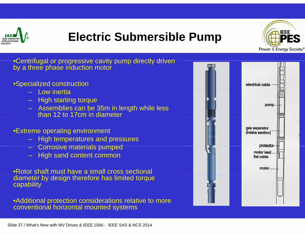
Electric Submersible Pump
•Centrifugal or progressive cavity pump directly driven•Centrifugal or progressive cavity pump directly driven by a three phase induction motor
•Specialized construction – Low inertia– High starting torque– Assemblies can be 35m in length while less
than 12 to 17cm in diameter
•Extreme operating environment– High temperatures and pressures
Corrosive materials pumped– Corrosive materials pumped– High sand content common
•Rotor shaft must have a small cross sectional diameter by design therefore has limited torque capability
•Additional protection considerations relative to more
Slide 37 / What's New with MV Drives & IEEE 1566 - IEEE SAS & NCS 2014
pconventional horizontal mounted systems
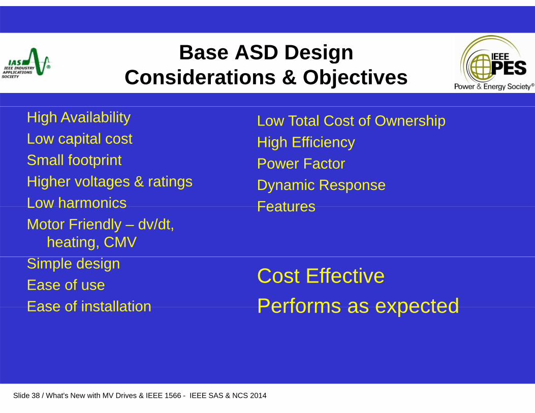
Base ASD DesignBase ASD Design Considerations & Objectives
Low Total Cost of OwnershipHigh Efficiency
High AvailabilityLow capital costS ll f t i t Power Factor
Dynamic ResponseFeatures
Small footprintHigher voltages & ratingsLow harmonics FeaturesLow harmonicsMotor Friendly – dv/dt,
heating, CMV
Cost EffectivePerforms as expected
Simple designEase of useEase of installation Performs as expectedEase of installation
Slide 38 / What's New with MV Drives & IEEE 1566 - IEEE SAS & NCS 2014

Basic ASD Design Considerations
•Wide variety of semi-conductors available
– DiodeSCR– SCR
– IGBT– IGCT– SGCT
• Each has its own set of design characteristics - strengths / weaknesses
Slide 39 / What's New with MV Drives & IEEE 1566 - IEEE SAS & NCS 2014
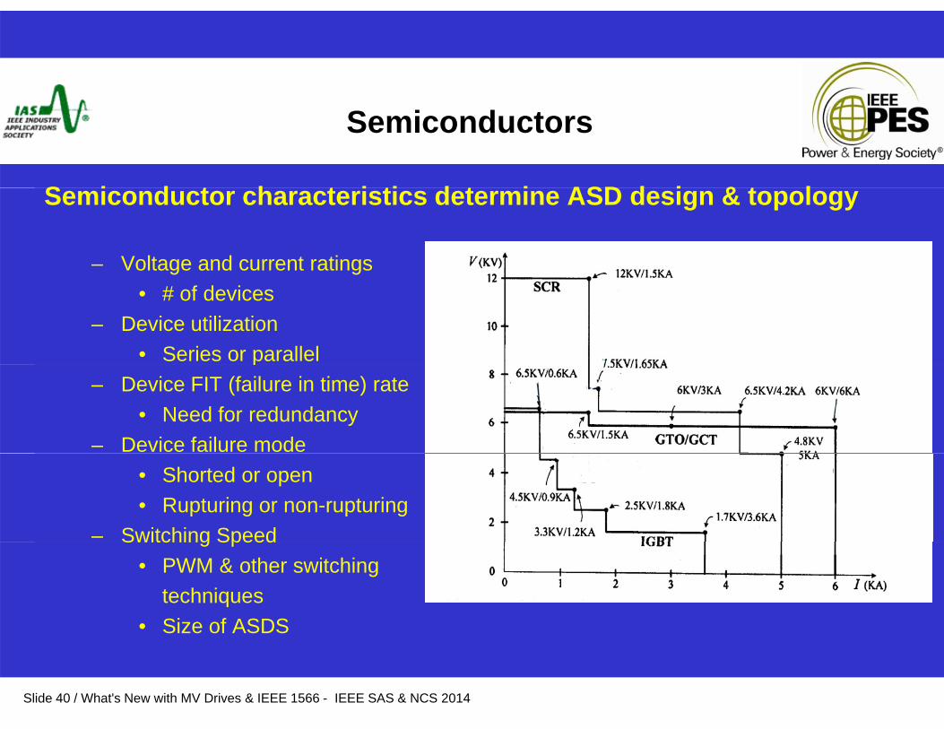
Semiconductors
S i d t h t i ti d t i ASD d i & t lSemiconductor characteristics determine ASD design & topology
– Voltage and current ratings• # of devices
– Device utilization • Series or parallel p
– Device FIT (failure in time) rate• Need for redundancy
– Device failure mode• Shorted or open• Rupturing or non-rupturing
– Switching SpeedSwitching Speed • PWM & other switching
techniques • Size of ASDS
Slide 40 / What's New with MV Drives & IEEE 1566 - IEEE SAS & NCS 2014
Size of ASDS
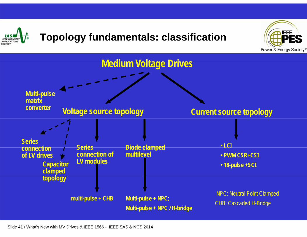
Topology fundamentals: classification
M di V lt D iMedium Voltage Drives
Voltage source topology Current source topology
Multi-pulse matrix converter
Series connection Series • LCIDiode clampedconnection of LV drives
Series connection of LV modules
LCI• PWM CSR+CSI• 18-pulse +SCI
Diode clamped multilevel
Capacitor clamped t l
multi-pulse + CHB Multi-pulse + NPC;
topology
NPC: Neutral Point ClampedCHB: Cascaded H-Bridge
Slide 41 / What's New with MV Drives & IEEE 1566 - IEEE SAS & NCS 2014
Multi-pulse + NPC / H-bridgeCHB: Cascaded H Bridge
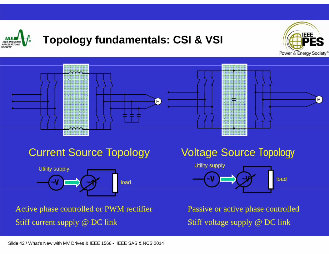
Topology fundamentals: CSI & VSI
M
Current Source Topology Voltage Source Topologyp gy g p gy
~V~V ~~
Utility supply
load ~V~V ~V~V
Utility supply
load
Active phase controlled or PWM rectifierS iff l @ DC li k
Passive or active phase controlled S iff l l @ DC li k
Slide 42 / What's New with MV Drives & IEEE 1566 - IEEE SAS & NCS 2014
Stiff current supply @ DC link Stiff voltage supply @ DC link
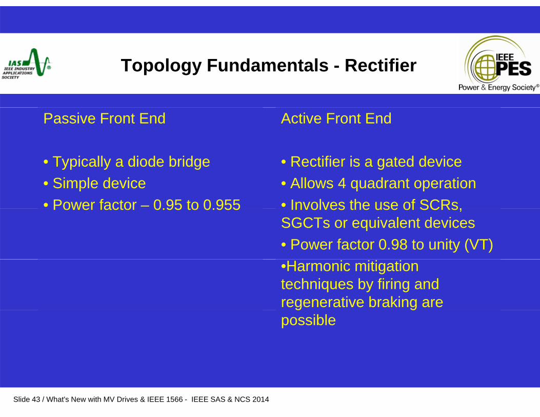
Topology Fundamentals - Rectifier
Passive Front End
T i ll di d b id
Active Front End
R tifi i t d d i• Typically a diode bridge• Simple device• Power factor – 0.95 to 0.955
• Rectifier is a gated device• Allows 4 quadrant operation• Involves the use of SCRs,Power factor 0.95 to 0.955 Involves the use of SCRs, SGCTs or equivalent devices• Power factor 0.98 to unity (VT)•Harmonic mitigation techniques by firing and regenerative braking are g gpossible
Slide 43 / What's New with MV Drives & IEEE 1566 - IEEE SAS & NCS 2014
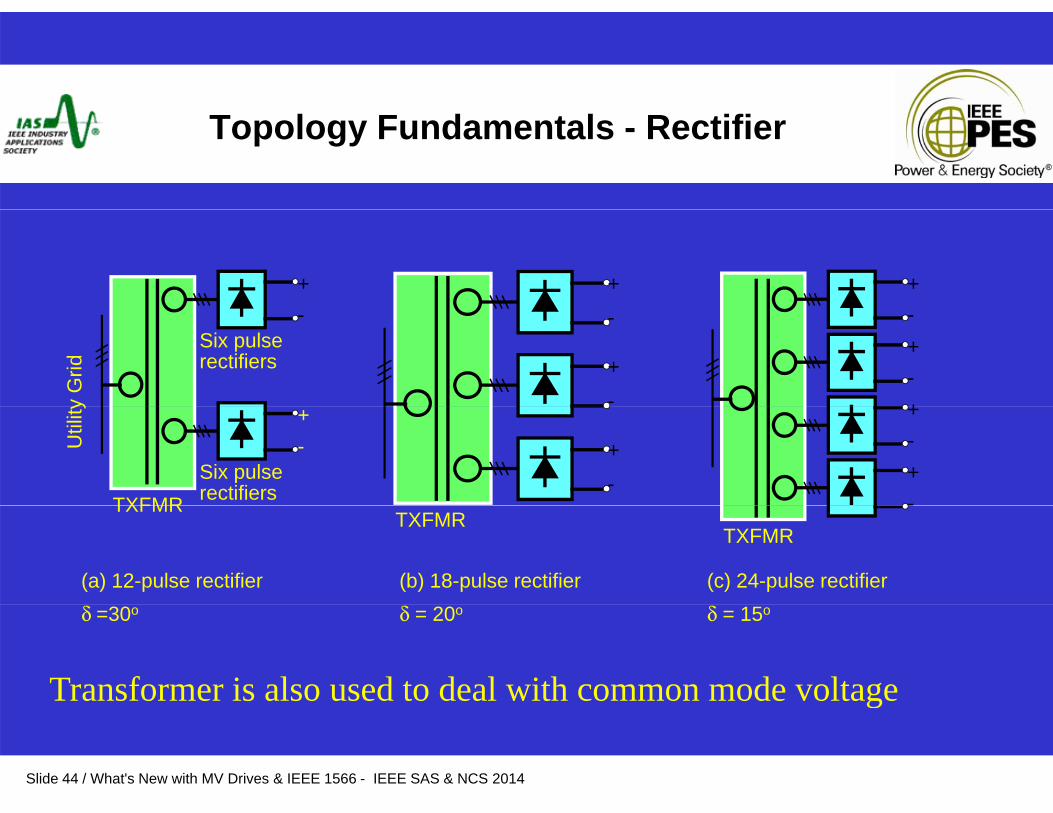
Topology Fundamentals - Rectifier
+ + +
Six pulse rectifiers
-
y G
rid
-
+-
+-+
-
Six pulse rectifiers
+-
TXFMR
Util
ity
+-
+-+-TXFMR
(a) 12-pulse rectifier
TXFMRTXFMR
-
(b) 18-pulse rectifier (c) 24-pulse rectifier δ =30o δ = 20o δ = 15o
Transformer is also used to deal with common mode voltage
Slide 44 / What's New with MV Drives & IEEE 1566 - IEEE SAS & NCS 2014
g
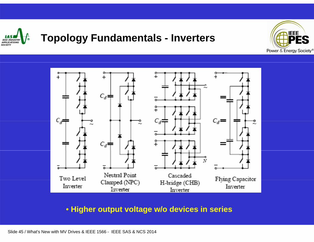
Topology Fundamentals - Inverters
• Higher output voltage w/o devices in series
Slide 45 / What's New with MV Drives & IEEE 1566 - IEEE SAS & NCS 2014
• Higher output voltage w/o devices in series
Topology Fundamentals – Voltage Source Drives
Variable Voltage Inverter (VVI)
Voltage Source Inverter (VSI – PWM)
Multilevel Voltage Source Inverter (MVSI)
S C (C )Multilevel Voltage Source Cascaded H bridge (CHB)
Slide 46 / What's New with MV Drives & IEEE 1566 - IEEE SAS & NCS 2014
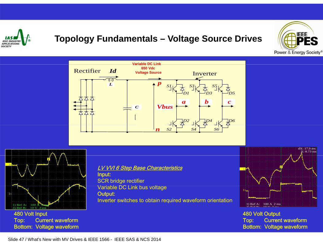
Topology Fundamentals – Voltage Source Drives
Variable DC Link
L
Id Inverter
S1 S5S3
D1 D3 D5
Rectifier
p
Variable DC Link 650 Vdc
Voltage Source
SMPS
C Vbus
D2 D4 D6
a b c
dX: 17.9 ms X: 8.73 ms
S2 S6S4n
T
1 >T
TT
1 >LV VVI 6 Step Base CharacteristicsInput:SCR bridge rectifierV i bl DC Li k b lt
480 Volt Input 480 Volt Output
TT
2 >
1) Ref A: 100 A 2 ms 2) Ref B: 10 V 2 ms
2 >
1) Ref A: 100 A 2 ms 2) Ref B: 10 V 2 ms
Variable DC Link bus voltageOutput:Inverter switches to obtain required waveform orientation
Slide 47 / What's New with MV Drives & IEEE 1566 - IEEE SAS & NCS 2014
pTop: Current waveform Bottom: Voltage waveform
pTop: Current waveform Bottom: Voltage waveform

VSI PWM 2 L l
6 Pulse Rectifier, DC Link capacitor & IGBT Inverter
VSI – PWM 2 Level
L
Id Inverter
S1 S5S3
Rectifier
p
Fixed DC Link 650 Vdc
Voltage Source
, p
xxxx
C Vbus
S1 S5S3
D1 D3 D5
a b c
p
Diodes
xxxx
x
SMPS
S2 S6S4
D2 D4 D6
n
xxxx
x
LV VSI PWM 2 Level Base Characteristics 480 Volt Output
xxx
Input:•Diode bridge rectifier typically 6 pulse •Fixed DC Link bus voltageOutput:•PWM inverter switches @ high frequencies (2 – 10 kHz) to obtain required output voltage and harmonic elimination
Top: Current waveform Bottom: Voltage waveform
Slide 48 / What's New with MV Drives & IEEE 1566 - IEEE SAS & NCS 2014
@ g q ( ) q p g• Most common LV technique employed in industry presently
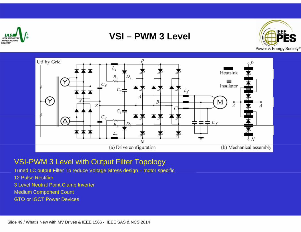
VSI – PWM 3 Level
VSI-PWM 3 Level with Output Filter TopologyTuned LC output Filter To reduce Voltage Stress design – motor specific p g g p12 Pulse Rectifier3 Level Neutral Point Clamp InverterMedium Component CountGTO or IGCT Power Devices
Slide 49 / What's New with MV Drives & IEEE 1566 - IEEE SAS & NCS 2014
GTO or IGCT Power Devices
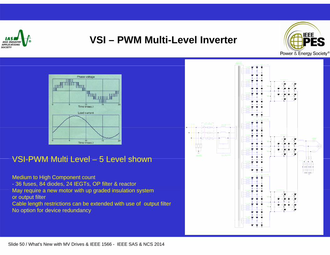
VSI – PWM Multi-Level Inverter
VSI PWM Multi Level 5 Level shownVSI-PWM Multi Level – 5 Level shown
Medium to High Component count- 36 fuses, 84 diodes, 24 IEGTs, OP filter & reactorMay require a new motor with up graded insulation systemMay require a new motor with up graded insulation system or output filterCable length restrictions can be extended with use of output filterNo option for device redundancy
Slide 50 / What's New with MV Drives & IEEE 1566 - IEEE SAS & NCS 2014
M l i L l C d d H B id
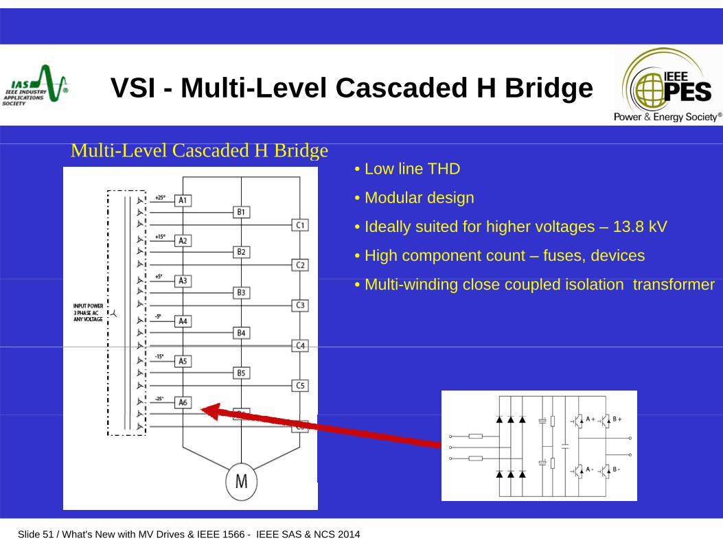
VSI - Multi-Level Cascaded H Bridge
• Low line THD
• Modular design
Multi-Level Cascaded H Bridge
• Ideally suited for higher voltages – 13.8 kV
• High component count – fuses, devices
M lti i di l l d i l ti t f• Multi-winding close coupled isolation transformer
Slide 51 / What's New with MV Drives & IEEE 1566 - IEEE SAS & NCS 2014

Topology Fundamentals – Current Source
Load Commutated Inverter (LCI)
Capacitor Assisted Current Source Inverter (CACSI)
Current Source Inverter (CSI – PWM GTO) – 1989 to 2000
C S f & (CS & CS )Current Source PWM Rectifier & PWM Inverter (CSI & CSR PWM)– Introduced in 2000 – CMVE addition in 2004– CMVE addition in 2004
Slide 52 / What's New with MV Drives & IEEE 1566 - IEEE SAS & NCS 2014
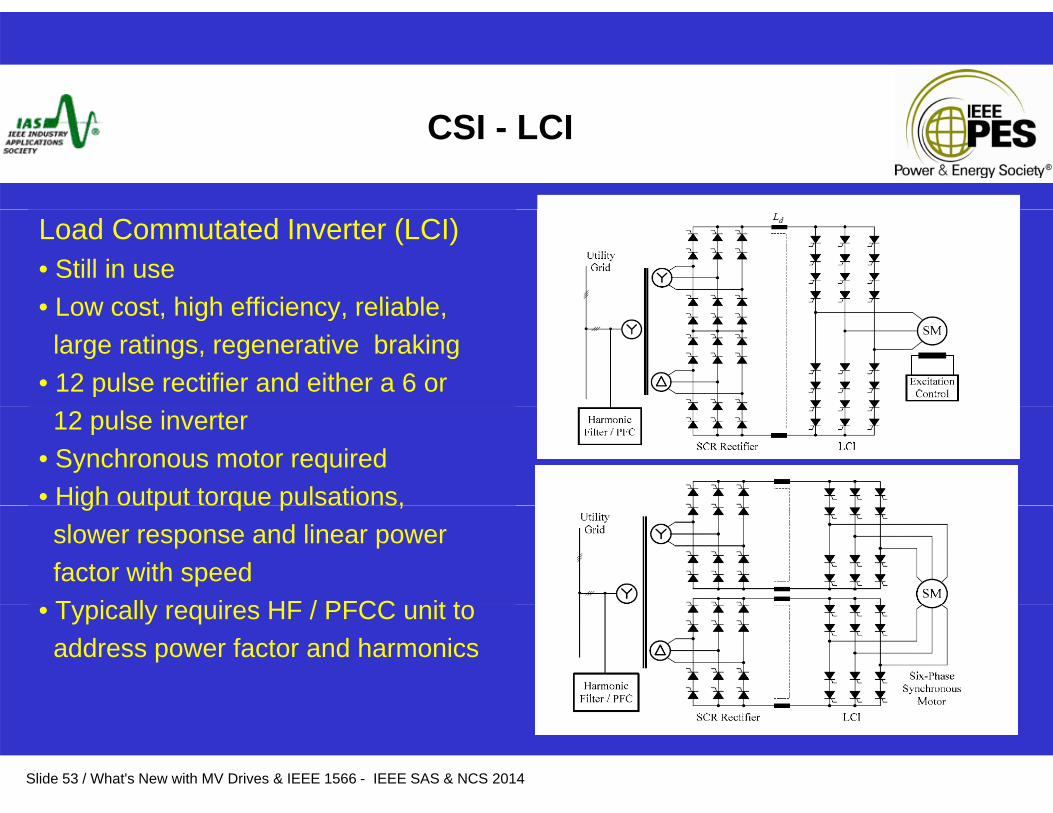
CSI - LCI
Load Commutated Inverter (LCI)• Still in use• Low cost high efficiency reliable• Low cost, high efficiency, reliable, large ratings, regenerative braking
• 12 pulse rectifier and either a 6 or 12 pulse inverter
• Synchronous motor required• High output torque pulsations, g ou pu o que pu sa o s,slower response and linear power factor with speedT i ll i HF / PFCC it t• Typically requires HF / PFCC unit to address power factor and harmonics
Slide 53 / What's New with MV Drives & IEEE 1566 - IEEE SAS & NCS 2014
CSI - CACSI
Capacitor Assisted Current Source Inverter (CACSI)• Introduced in late 70’s early 80’s • SCR rectifier – 6 or 12 pulse• SCR rectifier – 6 or 12 pulse• Large DC link inductor• SCR inverter, a large output filter capacitor is required > 1 pu• Capacitor assists the SCR commutation of the inverter at high speeds• A crowbar or commutation circuit is used to commutate the SCRs of the inverter at low speeda o speed
• Limited effective speed range – 30 to 60 hz• No PWM techniques were employed
R i d HF / PFCC it• Required HF / PFCC unit• Many still in service
Slide 54 / What's New with MV Drives & IEEE 1566 - IEEE SAS & NCS 2014
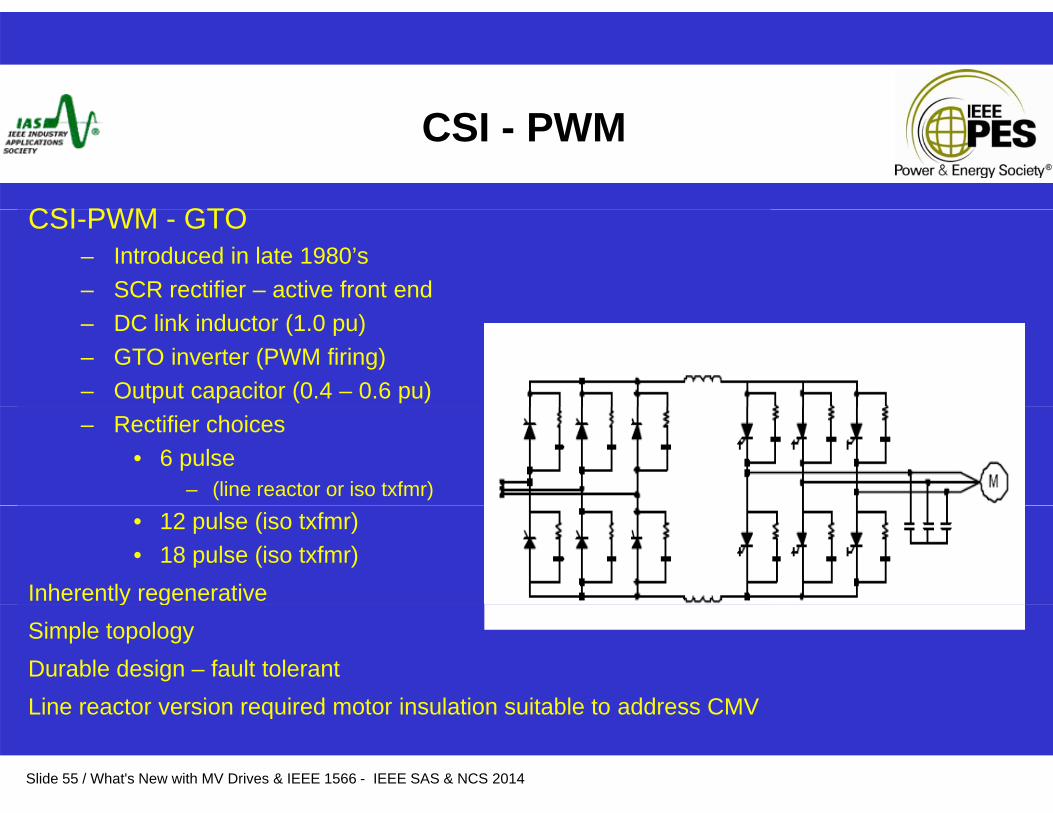
CSI - PWM
CSI PWM GTOCSI-PWM - GTO – Introduced in late 1980’s– SCR rectifier – active front end– DC link inductor (1.0 pu)– GTO inverter (PWM firing)– Output capacitor (0.4 – 0.6 pu)– Rectifier choices
• 6 pulse – (line reactor or iso txfmr)
• 12 pulse (iso txfmr)• 18 pulse (iso txfmr)
Inherently regenerativey gSimple topologyDurable design – fault tolerantLine reactor version required motor insulation suitable to address CMV
Slide 55 / What's New with MV Drives & IEEE 1566 - IEEE SAS & NCS 2014
Line reactor version required motor insulation suitable to address CMV
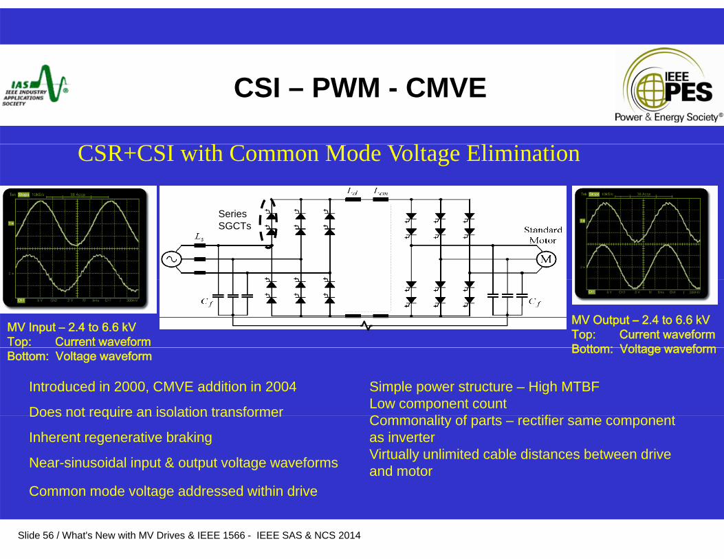
CSI – PWM - CMVE
Series
CSR+CSI with Common Mode Voltage Elimination
Series SGCTs
MV Input – 2.4 to 6.6 kVTop: Current waveform
MV Output – 2.4 to 6.6 kVTop: Current waveform Bottom: Voltage waveform
Introduced in 2000, CMVE addition in 2004
Does not require an isolation transformer
Simple power structure – High MTBFLow component count C lit f t tifi t
pBottom: Voltage waveform Bottom: Voltage waveform
Does not require an isolation transformer
Inherent regenerative braking
Near-sinusoidal input & output voltage waveforms
Commonality of parts – rectifier same component as inverterVirtually unlimited cable distances between drive and motor
Slide 56 / What's New with MV Drives & IEEE 1566 - IEEE SAS & NCS 2014
Common mode voltage addressed within drive
Industry News & Trends
• Increased use of ASDs• Less Gas compression electrificationp• Class H bridge patent expires April 2014 • Cooling – minimize air conditioning• New topologies – AFE & transformer-less• Cross pollination of topologies
Slide 57 / What's New with MV Drives & IEEE 1566 - IEEE SAS & NCS 2014
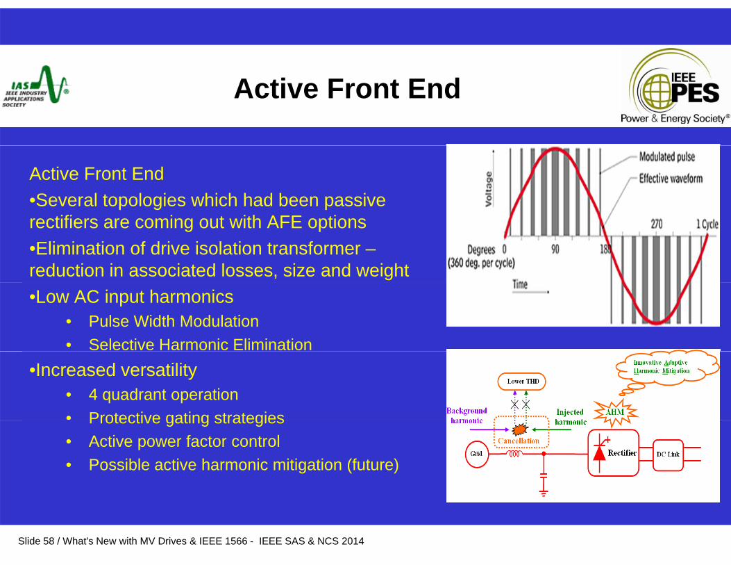
Active Front End
Active Front End•Several topologies which had been passive rectifiers are coming out with AFE options•Elimination of drive isolation transformer –reduction in associated losses, size and weight•Low AC input harmonics
• Pulse Width Modulation• Selective Harmonic Elimination
•Increased versatility• 4 quadrant operation• Protective gating strategiesProtective gating strategies• Active power factor control • Possible active harmonic mitigation (future)
Slide 58 / What's New with MV Drives & IEEE 1566 - IEEE SAS & NCS 2014
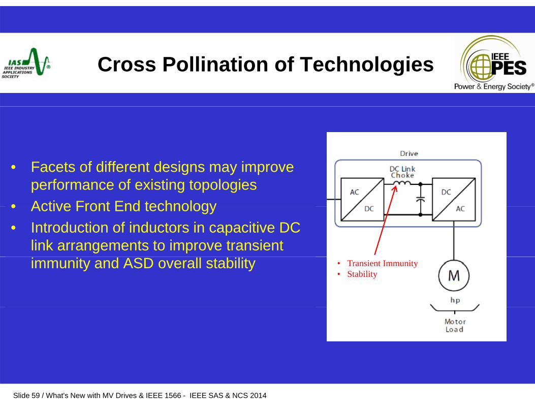
C fCross Pollination of Technologies
• Facets of different designs may improve performance of existing topologies
• Active Front End technology• Active Front End technology• Introduction of inductors in capacitive DC
link arrangements to improve transient immunity and ASD overall stability • Transient Immunity
• Stability
Slide 59 / What's New with MV Drives & IEEE 1566 - IEEE SAS & NCS 2014
Industry News & Trends
• More demand & extensive use of information• Intelligence – predictive maintenance – drive and application• Increased Connectivity
• EtherNet• Remote Communications
• Cloud ServicePLC i t ti f• PLC integration – ease of use
• Block Instructions • Automatic Device Configuration
• Integrated motion
Slide 60 / What's New with MV Drives & IEEE 1566 - IEEE SAS & NCS 2014
Ethernet
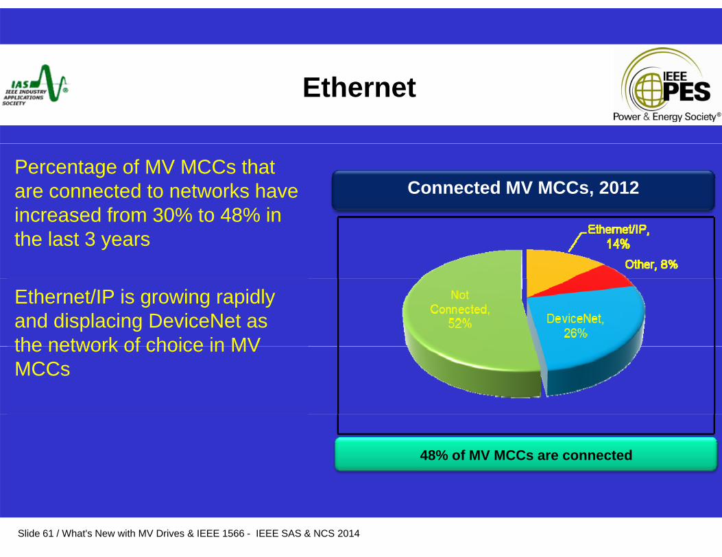
Percentage of MV MCCs that are connected to networks have i d f 30% t 48% i
Connected MV MCCs, 2012increased from 30% to 48% in the last 3 years
Ethernet/IP is growing rapidly and displacing DeviceNet as the network of choice in MVthe network of choice in MV MCCs
48% of MV MCCs are connected
Slide 61 / What's New with MV Drives & IEEE 1566 - IEEE SAS & NCS 2014
Remote HMI
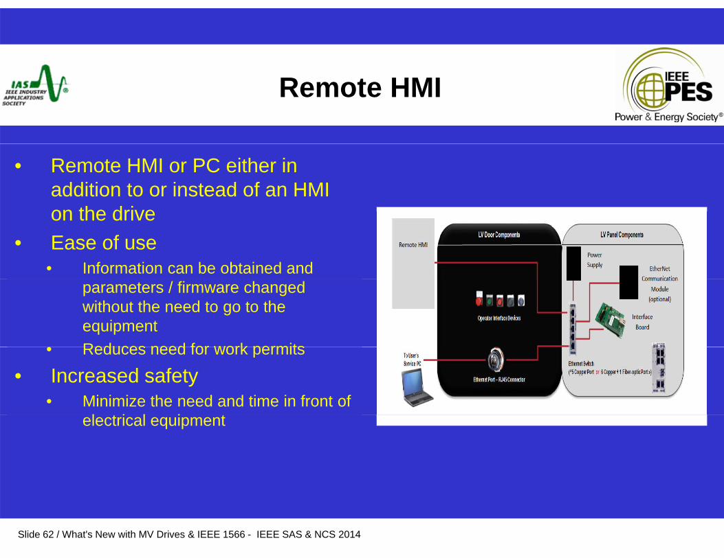
• Remote HMI or PC either in addition to or instead of an HMI on the driveon the drive
• Ease of use• Information can be obtained and
parameters / firmware changed without the need to go to the equipment
• Reduces need for work permits• Reduces need for work permits
• Increased safety• Minimize the need and time in front of
l t i l i telectrical equipment
Slide 62 / What's New with MV Drives & IEEE 1566 - IEEE SAS & NCS 2014
Remote Monitoring
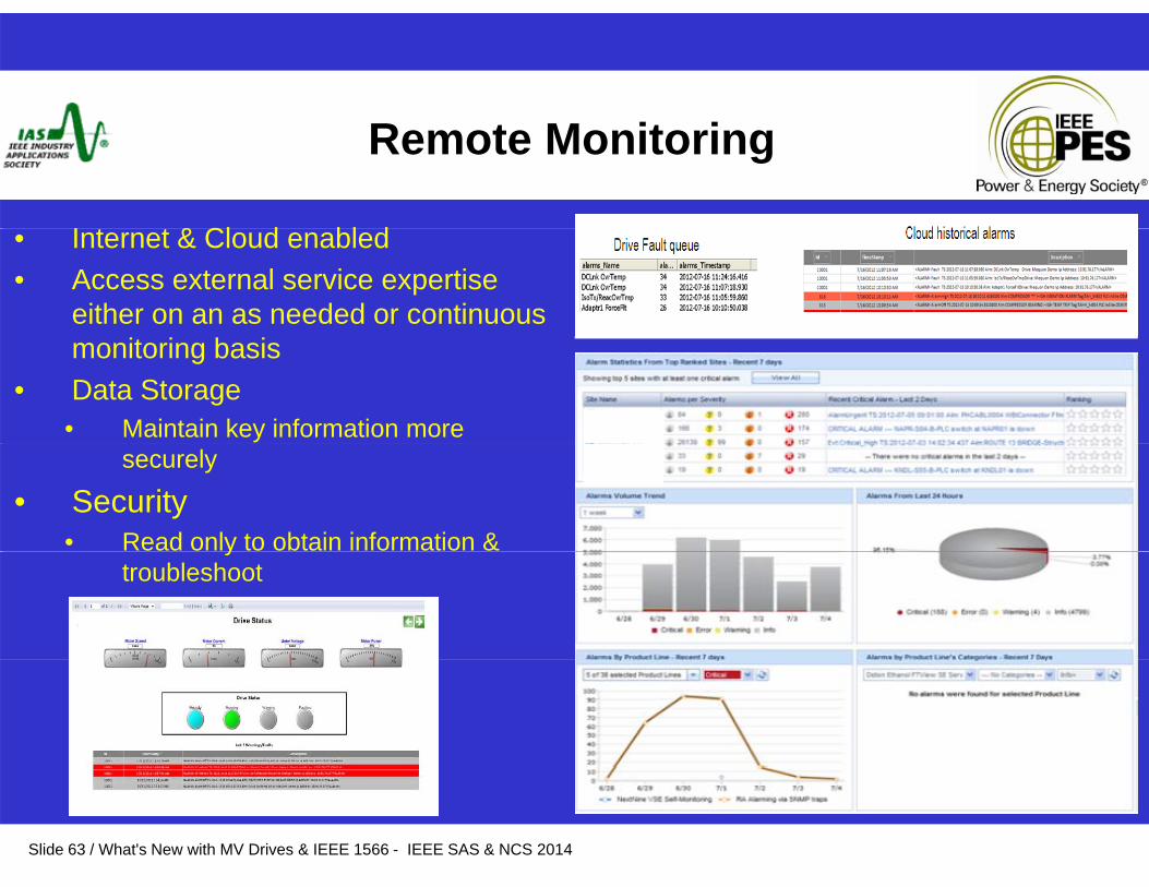
I t t & Cl d bl d• Internet & Cloud enabled • Access external service expertise
either on an as needed or continuous monitoring basis
• Data Storage• Maintain key information more
securely
• Security • Read only to obtain information & y
troubleshoot
Slide 63 / What's New with MV Drives & IEEE 1566 - IEEE SAS & NCS 2014
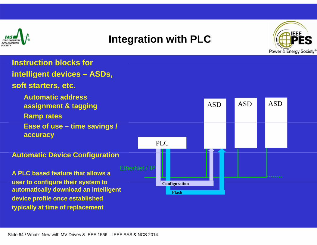
Integration with PLC
Instruction blocks forInstruction blocks forintelligent devices – ASDs, soft starters, etc.
Automatic address assignment & taggingRamp rates
ASD ASD ASD
Ease of use – time savings / accuracy
A i D i C fi iPLC
Automatic Device Configuration
A PLC based feature that allows a user to configure their system to
EtherNet / IP
C fi iuser to configure their system to automatically download an intelligent device profile once established typically at time of replacement
Flash
Configuration
Slide 64 / What's New with MV Drives & IEEE 1566 - IEEE SAS & NCS 2014

I d M iIntegrated Motion
Coordinates devices in a manner• EtherNet Enabled• Synchronized motion• “Electronic drive shaft”
Coordinates devices in a manner that’s similar to our own methods forcoordinating meetings and events
Electronic drive shaft• Equivalent to a process sequencer• Improve troubleshooting
Ti d t t t
– All members (devices) have clocks to compare time to an absolute base and scale
• Time date stamp events• Correlate activities on the system
– A destination (position) is targeted for the event
– A time (timestamp) is set for when the event shall occur
– A message is sent to each member (device) to meet at a given place at the pre-determined time
MeetingConf Rm 2:00 pm
Slide 65 / What's New with MV Drives & IEEE 1566 - IEEE SAS & NCS 2014
Conf Rm 2:00 pm
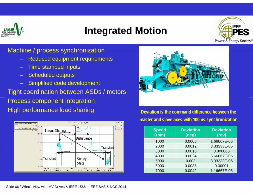
Integrated Motion
Machine / process synchronizationMachine / process synchronization– Reduced equipment requirements– Time stamped inputs
Scheduled outputs– Scheduled outputs– Simplified code development
Tight coordination between ASDs / motorsProcess component integrationHigh performance load sharing Deviation is the command difference between the
master and slave axes with 100 ns synchronization
Speed(rpm)
Deviation(deg)
Deviation(rev)
1000 0.0006 1.66667E-062000 0 0012 3 33333E 06
aste a d s a e a es t 00 s sy c o at o
Torque Sharing
Disturbance
2000 0.0012 3.33333E-063000 0.0018 0.0000054000 0.0024 6.66667E-065000 0.003 8.33333E-066000 0.0036 0.00001
Transient
Transient
Steady State
Slide 66 / What's New with MV Drives & IEEE 1566 - IEEE SAS & NCS 2014
7000 0.0042 1.16667E-05
Industry News & Trends
• Integral motor protection
• Safety• Arc Flash / Arc Mitigationg• SIL ratings
P t M t• Permanent Magnet
Slide 67 / What's New with MV Drives & IEEE 1566 - IEEE SAS & NCS 2014
Arc Mitigation - ASD
Under discussion in IEEE 1566 WGChallenge is to determine theChallenge is to determine the industry direction
•Arc Resistant •Light Detection•Other?
Slide 68 / What's New with MV Drives & IEEE 1566 - IEEE SAS & NCS 2014
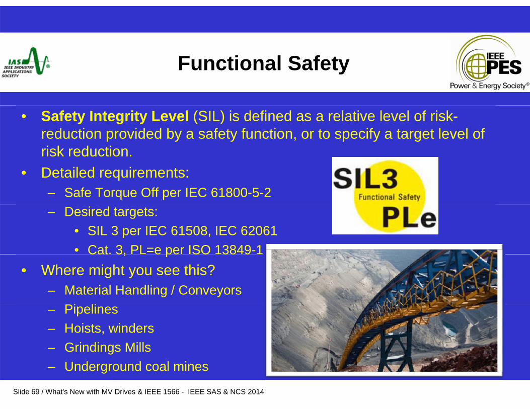
F i l S fFunctional Safety
• Safety Integrity Level (SIL) is defined as a relative level of risk-reduction provided by a safety function, or to specify a target level of risk reduction.risk reduction.
• Detailed requirements:– Safe Torque Off per IEC 61800-5-2– Desired targets:
• SIL 3 per IEC 61508, IEC 62061• Cat. 3, PL=e per ISO 13849-1Cat 3, e pe SO 38 9
• Where might you see this?– Material Handling / Conveyors – Pipelines– Hoists, winders– Grindings Mills
Slide 69 / What's New with MV Drives & IEEE 1566 - IEEE SAS & NCS 2014
g– Underground coal mines
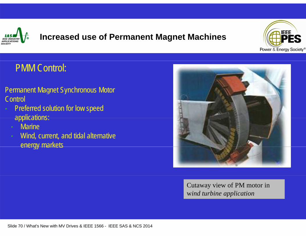
Increased use of Permanent Magnet Machines
Permanent Magnet Synchronous Motor
PMM Control:
Permanent Magnet Synchronous Motor Control• Preferred solution for low speed
applications:applications:• Marine• Wind, current, and tidal alternative
energy marketsenergy markets
Cutaway view of PM motor in wind turbine application
Slide 70 / What's New with MV Drives & IEEE 1566 - IEEE SAS & NCS 2014
Industry News & Trends
• Role of Operations & Maintenance in decision making process• Decline of Subject Matter Expertise • Increased demand for services & support
• Application Supportpp pp• Field Support• Training
El t i l• Electronic manuals• Electronic knowledge and product notification
Slide 71 / What's New with MV Drives & IEEE 1566 - IEEE SAS & NCS 2014
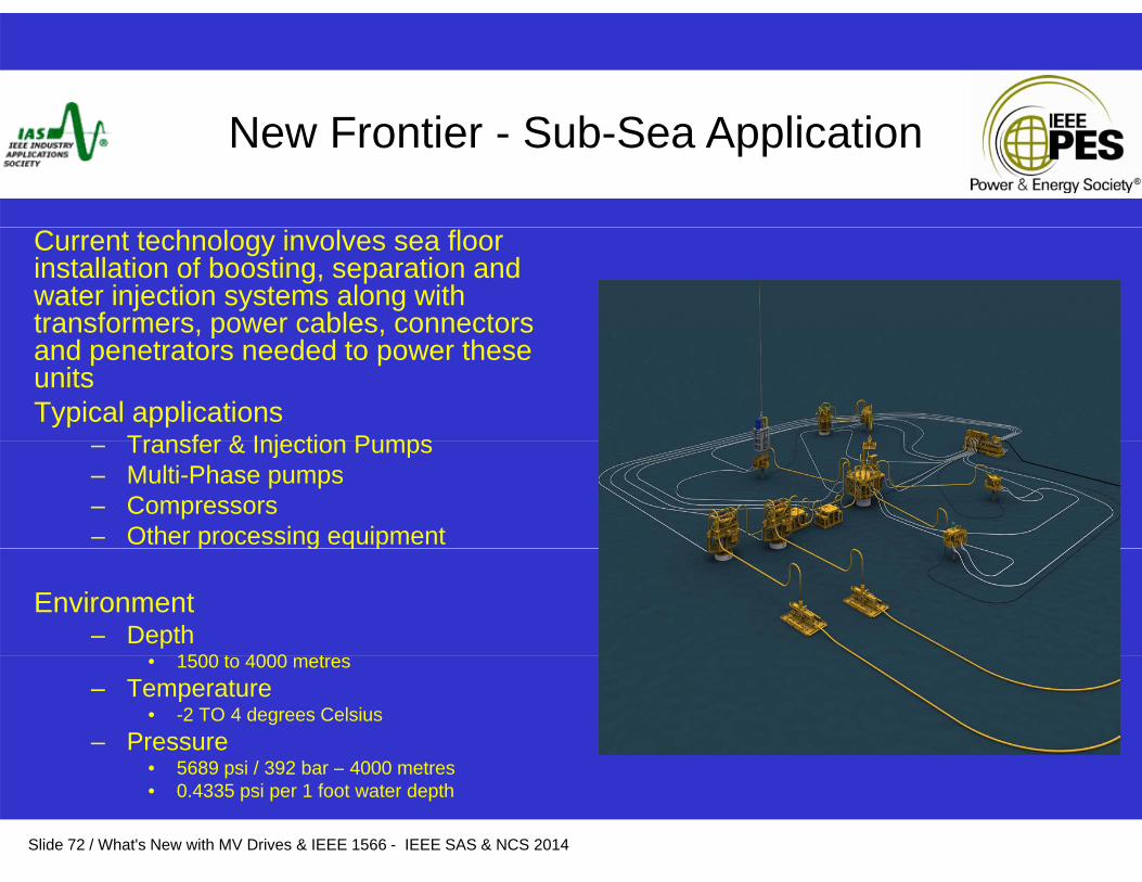
N F ti S b S A li tiNew Frontier - Sub-Sea Application
Current technology involves sea floor installation of boosting, separation and water injection systems along with transformers, power cables, connectors , p ,and penetrators needed to power these units Typical applications
Transfer & Injection Pumps– Transfer & Injection Pumps– Multi-Phase pumps– Compressors– Other processing equipmentp g q p
Environment– Depth
1500 t 4000 t• 1500 to 4000 metres– Temperature
• -2 TO 4 degrees Celsius– Pressure
5689 i / 392 b 4000 t
Slide 72 / What's New with MV Drives & IEEE 1566 - IEEE SAS & NCS 2014
• 5689 psi / 392 bar – 4000 metres• 0.4335 psi per 1 foot water depth
Ad t f S b S A hAdvantages of Sub-Sea Approach
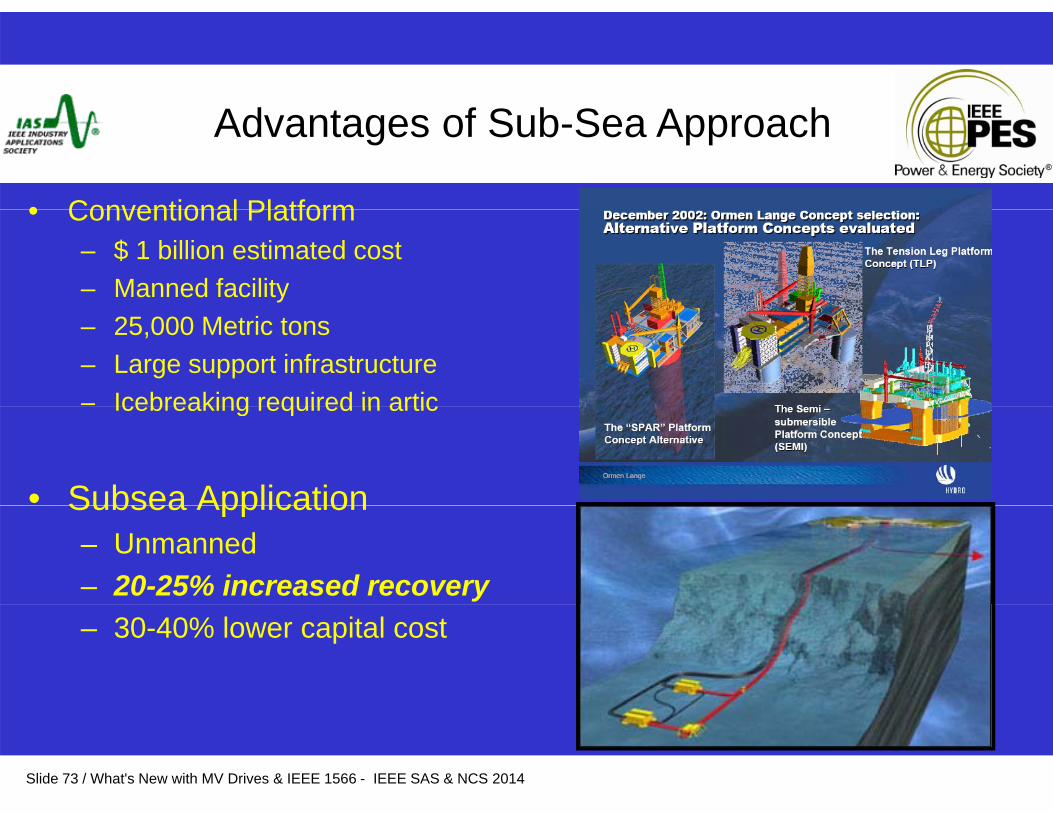
• Conventional Platform• Conventional Platform– $ 1 billion estimated cost– Manned facility– 25,000 Metric tons – Large support infrastructure– Icebreaking required in articIcebreaking required in artic
• Subsea ApplicationSubsea Application– Unmanned– 20-25% increased recovery– 30-40% lower capital cost
Slide 73 / What's New with MV Drives & IEEE 1566 - IEEE SAS & NCS 2014
Ad t f S b S A hAdvantages of Sub-Sea Approach
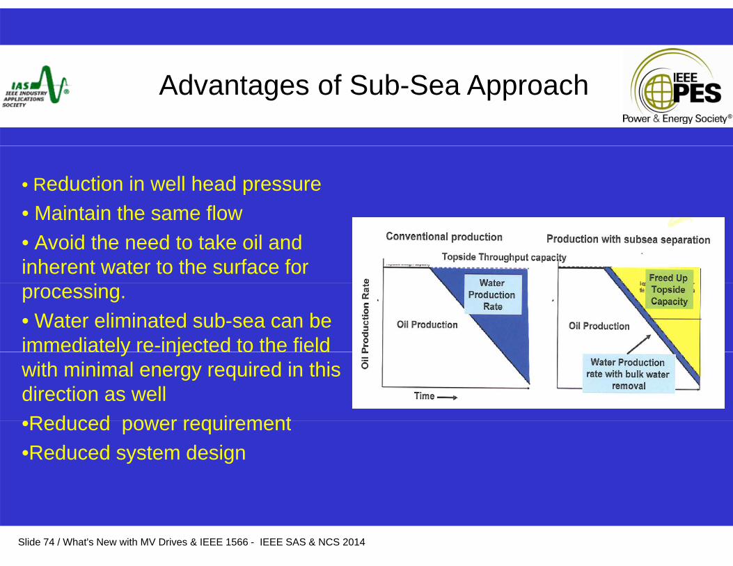
• Reduction in well head pressure• Maintain the same flow• Maintain the same flow • Avoid the need to take oil and inherent water to the surface for processing. • Water eliminated sub-sea can be immediately re-injected to the fieldimmediately re injected to the field with minimal energy required in this direction as well•Reduced power requirement•Reduced power requirement•Reduced system design
Slide 74 / What's New with MV Drives & IEEE 1566 - IEEE SAS & NCS 2014
D i i f S bDesigning for Subsea
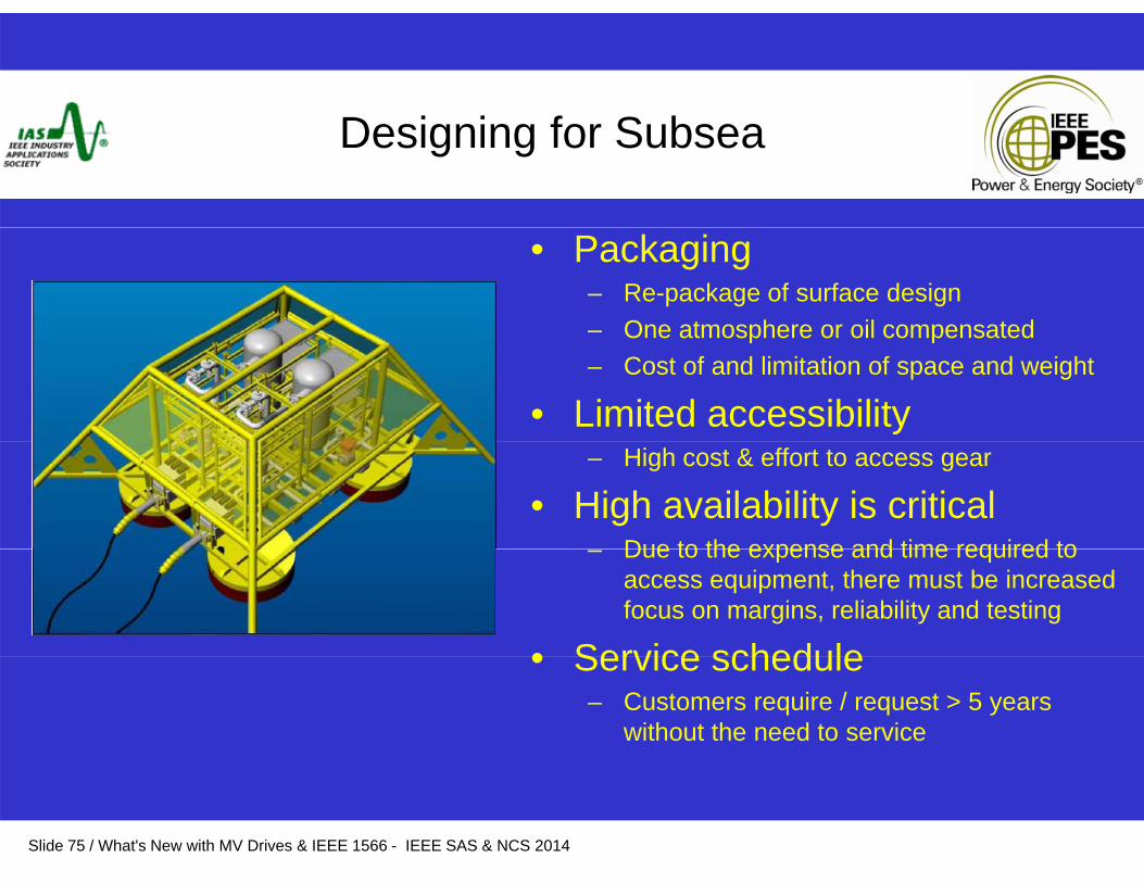
• Packaging– Re-package of surface design– One atmosphere or oil compensatedOne atmosphere or oil compensated– Cost of and limitation of space and weight
• Limited accessibility– High cost & effort to access gear
• High availability is criticalDue to the expense and time required to– Due to the expense and time required to access equipment, there must be increased focus on margins, reliability and testing
• Service schedule• Service schedule– Customers require / request > 5 years
without the need to service
Slide 75 / What's New with MV Drives & IEEE 1566 - IEEE SAS & NCS 2014
S CAdjustable Speed Drive Concepts
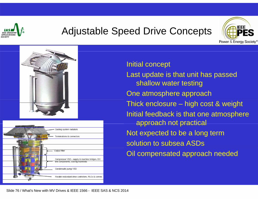
Initial conceptLast update is that unit has passedLast update is that unit has passed
shallow water testingOne atmosphere approachThick enclosure – high cost & weightInitial feedback is that one atmosphere
approach not practicalapproach not practicalNot expected to be a long term solution to subsea ASDsOil compensated approach needed
Slide 76 / What's New with MV Drives & IEEE 1566 - IEEE SAS & NCS 2014
S b St d GSubsea Study Group
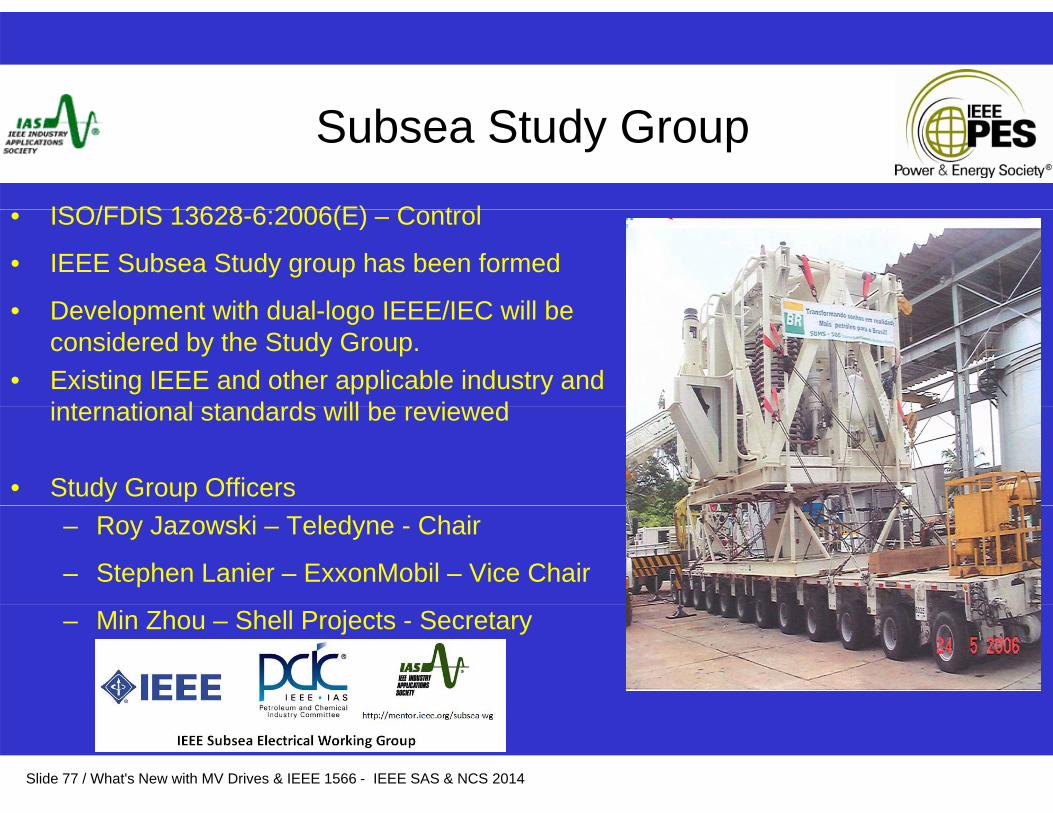
ISO/FDIS 13628 6 2006(E) C t l• ISO/FDIS 13628-6:2006(E) – Control
• IEEE Subsea Study group has been formed
• Development with dual logo IEEE/IEC will be• Development with dual-logo IEEE/IEC will be considered by the Study Group.
• Existing IEEE and other applicable industry and international standards ill be re ie edinternational standards will be reviewed
• Study Group Officers– Roy Jazowski – Teledyne - Chair
– Stephen Lanier – ExxonMobil – Vice Chair
– Min Zhou – Shell Projects - Secretary
Slide 77 / What's New with MV Drives & IEEE 1566 - IEEE SAS & NCS 2014

Expanding Applications list
MV D i I i bili iMV Drives Increasing capabilities– Expanding markets by improving performance, features & benefits– Power Factor improvement and control, VAR compensation– Comprehensive protection package for drive and motor– Permanent Magnet motor control– Process flexibility– Communication capabilities
• Variety of protocols• Integrated, transparent diagnostics automatically recording key g p g y g y
variables• Upgraded interface capabilities, incorporating manuals, drawings and
diagnostics– System type drive integration capabilities
Slide 78 / What's New with MV Drives & IEEE 1566 - IEEE SAS & NCS 2014
78
Summary
Numerous benefits of MV Drives– Energy savings
R d d l t i l d h i l di t b– Reduced electrical and mechanical disturbances– Enhanced process control– Improved reliabilityImproved reliability
Future of MV Drives lies in
• Improving features and benefitsE di d i i t d di li ti• Expanding drive use into more demanding applications
• Continued size and cost reductions• High availabilty
Slide 79 / What's New with MV Drives & IEEE 1566 - IEEE SAS & NCS 2014
High availabilty

Slide 80 / What's New with MV Drives & IEEE 1566 - IEEE SAS & NCS 2014
ASD History
• ASDs have been used in process applications for some time – since 70’s– Improved process control– Efficiency & energy savings– Allow starting on weak power systems within utility constraints– Eliminate mechanical components – valves gearboxes etcEliminate mechanical components valves, gearboxes, etc.– Reduce installation and maintenance costs
• Initially, as drives were new technology, the ASD was the projectWi h i i i i f f d h• With more extensive usage, innovation in terms of ease of use and other factors have made this simpler so the focus becomes application and required performance– Efficiency, power factor, etc.
Slide 81 / What's New with MV Drives & IEEE 1566 - IEEE SAS & NCS 2014

Large Adjustable Speed Drive Usage
• While drives have been in use since the 1970’s, usage has MV DRIVE SALESprogressed nearly exponentially• Currently a single manufacturer produces more drives in one year
6000
7000
UN
MV DRIVE SALES
p yin one facility than the total demand in year 2000• Northern Alberta represents 3000
4000
5000NITS
Spperhaps the highest concentration in the world. Majority of drives are current source
0
1000
2000
SOLD
01980 1985 1990 1995 2000 2005 2010 2015
YEAR
Slide 82 / What's New with MV Drives & IEEE 1566 - IEEE SAS & NCS 2014

Large Adjustable Speed Drive Usage
Reasons for increased usage– Need to reduce energy costs
Li it d ld id l t i l di t ib ti– Limited world wide electrical distribution– Improve motor performance – starting, dynamic – Industry acceptancey p– Environmental factors – greenhouse gas emissions – Technological improvements
Ease of design and use– Ease of design and use– Reduced footprint / ease of installation– ASD cost reductions - $$ per horsepower– Reliability– Proven technology
Slide 83 / What's New with MV Drives & IEEE 1566 - IEEE SAS & NCS 2014
Need for a performance standard
• Baseline for a variety of drive topology choices + benefits
• Many technology options, fast changing
• Provides industry wide alignment of terminology and approach
• Useful for suppliers to monitor industry needs• Useful for suppliers to monitor industry needs
• Need to define requirements and offeringq g
• Ability to make effective comparisons
Slide 84 / What's New with MV Drives & IEEE 1566 - IEEE SAS & NCS 2014
Need for a performance standard
Topology is discussed primarily as a means for technical personnel to understand performanceunderstand performanceAs can be seen, there are many variations in drive topologies Important items for ASD usersp
– Availability – MTBF / MTTR– Product life – 20 years
Ease of use– Ease of use– Maintenance – Features
• Regenerative braking• Communications / Connectivity
Slide 85 / What's New with MV Drives & IEEE 1566 - IEEE SAS & NCS 2014
Need for a performance standard
• Consolidates intent / requirements of various other standardsstandards
• IEC, NEMA• Eliminate confusionEliminate confusion • Reduce the time needed to define an application • Guiding direction for first time system designers• Guiding direction for first time system designers• Reference for more experienced users
Slide 86 / What's New with MV Drives & IEEE 1566 - IEEE SAS & NCS 2014

IEEE 1566 Objectives
• Stand alone document• Specify performance rather than design• Specify performance rather than design• Provide the required data sheets• Reduce confusionReduce confusion• Reflect industry trends & needs• Leverage on experience of numerous usersg p• Not all items can be achieved immediately
Slide 87 / What's New with MV Drives & IEEE 1566 - IEEE SAS & NCS 2014
IEEE STD 1566 STANDARD FOR PERFORMANCEIEEE STD. 1566 STANDARD FOR PERFORMANCE OF ASD AC DRIVES RATED 375 KW AND LARGER
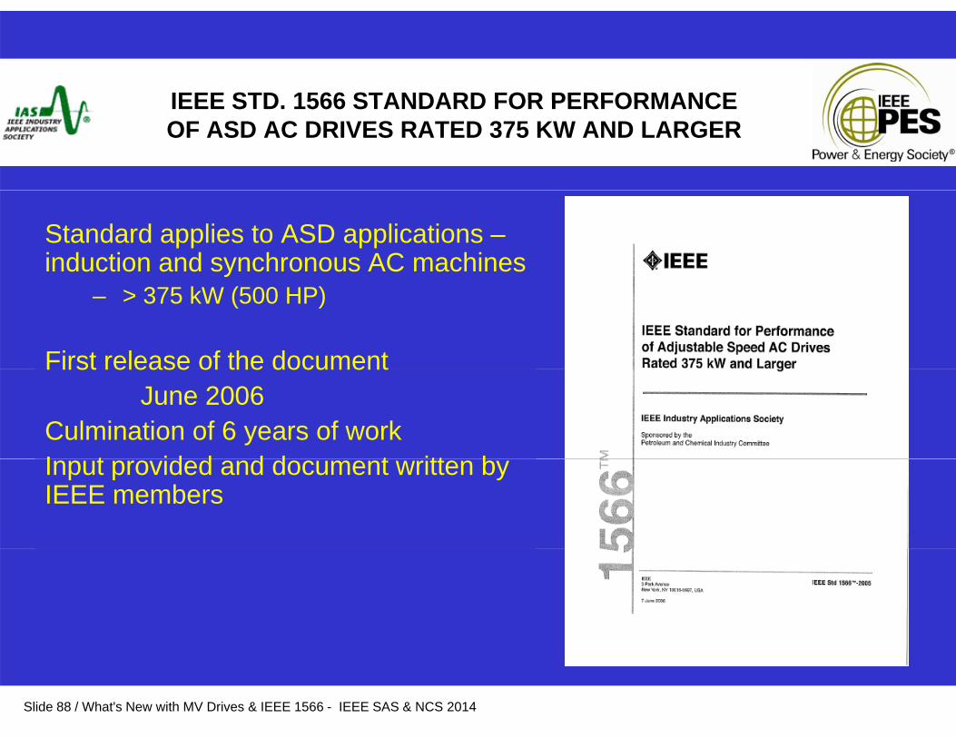
Standard applies to ASD applications –induction and synchronous AC machines
– > 375 kW (500 HP)
First release of the documentFirst release of the documentJune 2006
Culmination of 6 years of workI t id d d d t itt bInput provided and document written by IEEE members
Slide 88 / What's New with MV Drives & IEEE 1566 - IEEE SAS & NCS 2014
What’s New in 2014 revision
• Enhanced Data Sheets• Enhanced Data Sheets• Data Sheet Format – Excel
Data Sheet Guide• Data Sheet Guide• Adjustments to voltage sag & ride-through
I t d ti f fl h l t d t h t• Introduction of arc flash values to data sheets• Long Cables
M i• Marine• Generator Supply
Slide 89 / What's New with MV Drives & IEEE 1566 - IEEE SAS & NCS 2014
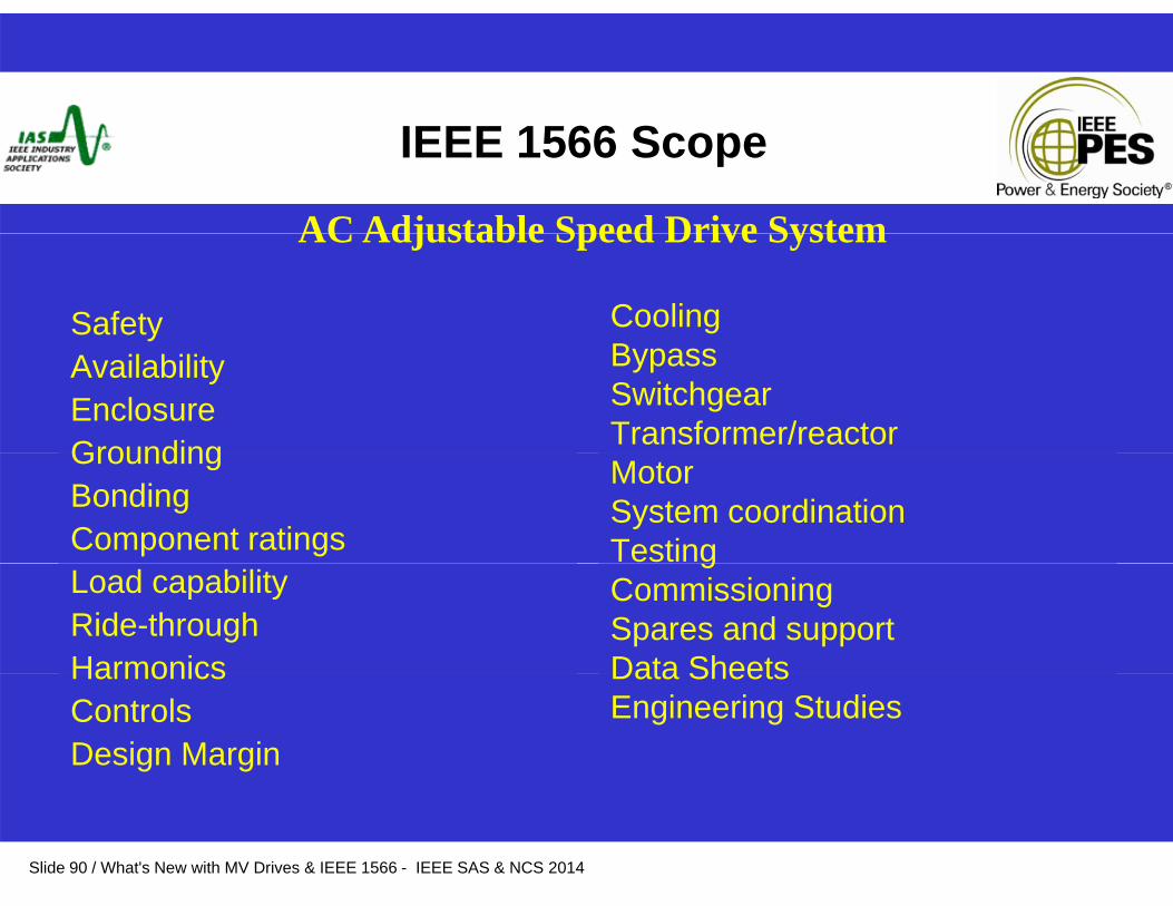
IEEE 1566 Scope
AC Adjustable Speed Drive System
Safety CoolingB
AC Adjustable Speed Drive System
AvailabilityEnclosure Grounding
BypassSwitchgearTransformer/reactorGrounding
BondingComponent ratings
MotorSystem coordinationTesting
Load capabilityRide-throughHarmonics
gCommissioningSpares and supportData SheetsHarmonics
ControlsDesign Margin
Data SheetsEngineering Studies
Slide 90 / What's New with MV Drives & IEEE 1566 - IEEE SAS & NCS 2014

Adjustable Speed Drive System
AC InputFi d
“An interconnected combination of equipment that provides a means of “An interconnected combination of equipment that provides a means of adjusting the speed of a mechanical load coupled to a motor“adjusting the speed of a mechanical load coupled to a motor“
Fixed Frequency,Fixed Voltage
AC-DCConversion
DC-ACConversion Motor
Input Impedance
OutputFilter
Input Switching
Device
AC Output;Adjustable Frequency,
CapacitorHarmonicFilter /
Adjustable Voltage
DC Link
Capacitoror
Inductor
Filter / PFCCUnit
Slide 91 / What's New with MV Drives & IEEE 1566 - IEEE SAS & NCS 2014
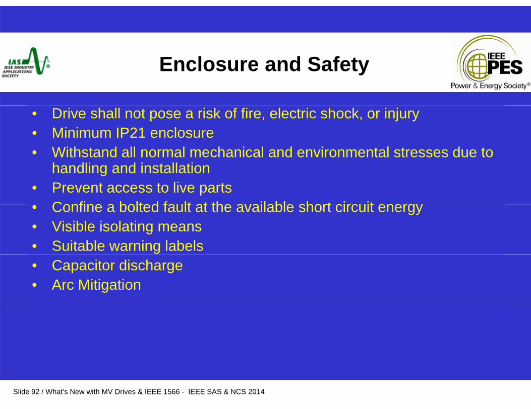
Enclosure and Safety
• Drive shall not pose a risk of fire, electric shock, or injury• Minimum IP21 enclosure• Withstand all normal mechanical and environmental stresses due toWithstand all normal mechanical and environmental stresses due to
handling and installation • Prevent access to live parts
Confine a bolted fault at the available short circuit energy• Confine a bolted fault at the available short circuit energy• Visible isolating means• Suitable warning labels • Capacitor discharge • Arc Mitigation
Slide 92 / What's New with MV Drives & IEEE 1566 - IEEE SAS & NCS 2014

Drive Topology
• Design requirements and performance rather than specific converter topology
• Power components conservatively rated• Redundancy (N+1) is discussed as an option• Replaceable components to be removable by no more
than two people • Isolation between power and control
Slide 93 / What's New with MV Drives & IEEE 1566 - IEEE SAS & NCS 2014
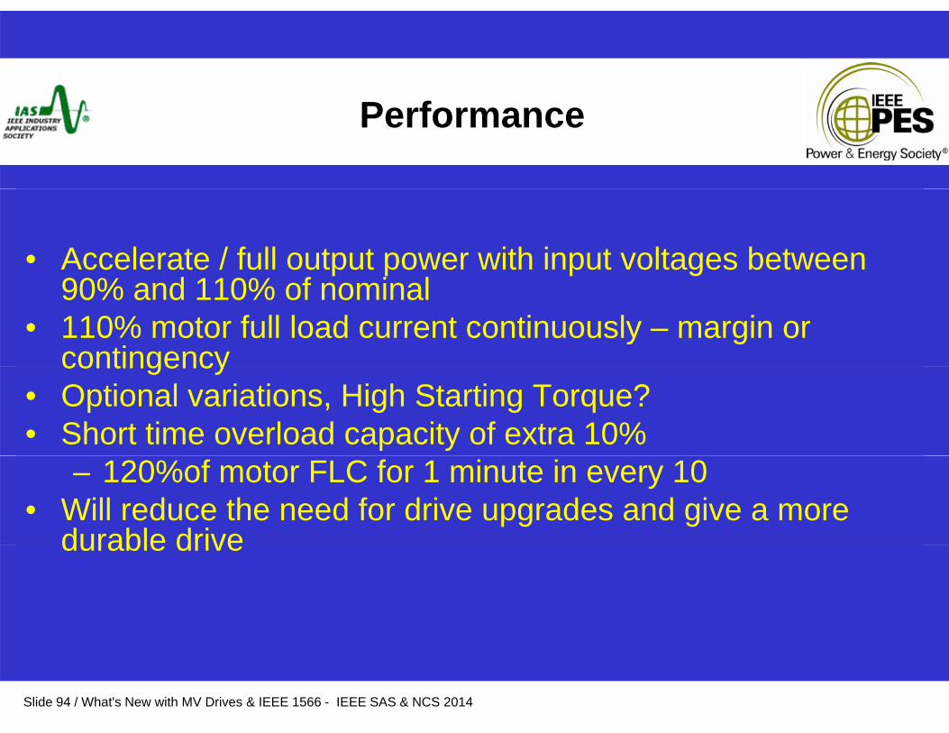
Performance
• Accelerate / full output power with input voltages between 90% d 110% f i l90% and 110% of nominal
• 110% motor full load current continuously – margin or contingencycontingency
• Optional variations, High Starting Torque?• Short time overload capacity of extra 10%
– 120%of motor FLC for 1 minute in every 10• Will reduce the need for drive upgrades and give a more
durable drivedurable drive
Slide 94 / What's New with MV Drives & IEEE 1566 - IEEE SAS & NCS 2014

Input Tolerance
• Transient Voltages
– Reliable operation with occasional input transients
• Flying Restart after 100% power loss of at least twoseconds
• Voltage Sags
Slide 95 / What's New with MV Drives & IEEE 1566 - IEEE SAS & NCS 2014
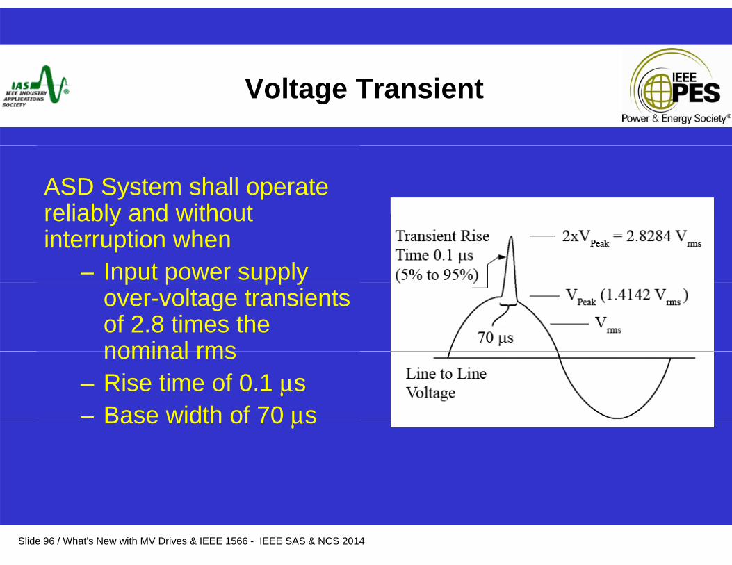
Voltage Transient
ASD System shall operate reliably and withoutreliably and without interruption when
– Input power supply p p pp yover-voltage transients of 2.8 times the nominal rmsnominal rms
– Rise time of 0.1 μs– Base width of 70 μsBase width of 70 μs
Slide 96 / What's New with MV Drives & IEEE 1566 - IEEE SAS & NCS 2014
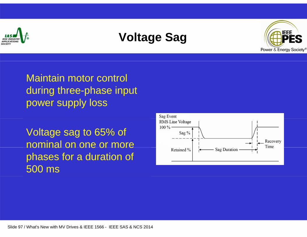
Voltage Sag
Maintain motor control during three phase inputduring three-phase input power supply loss
Voltage sag to 65% of nominal on one or morenominal on one or more phases for a duration of 500 ms
Slide 97 / What's New with MV Drives & IEEE 1566 - IEEE SAS & NCS 2014
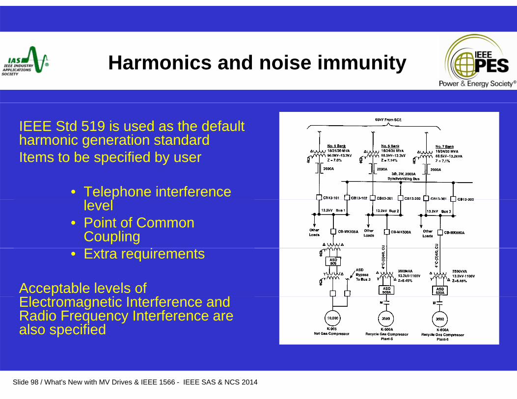
Harmonics and noise immunity
IEEE Std 519 is used as the default harmonic generation standardItems to be specified by user
• Telephone interference level
• Point of Common Coupling
• Extra requirements
Acceptable levels of El i I f dElectromagnetic Interference and Radio Frequency Interference are also specified
Slide 98 / What's New with MV Drives & IEEE 1566 - IEEE SAS & NCS 2014

Control
• Various control and communication options• Defines requirements for local/ remote operation• Alarm and fault diagnostics first out report sequenceAlarm and fault diagnostics, first out report sequence• Non volatile alarm and shutdown data • Trending and troubleshooting requirements• All data available on digital link• All data available on digital link• Include all required software and interface devices• Alarm and shutdown indications by both NC and NO contacts wired
to individual terminalsto individual terminals• Skip frequencies• Loss of speed reference signal - user selectable action
M i t i d– Maintain speed– Stop– Go to predefined speed level
Slide 99 / What's New with MV Drives & IEEE 1566 - IEEE SAS & NCS 2014
Bypass Operation
• Transfer motor between drive and utility, and back again• Useful for starting duty (speed control not required) or
approach to operational redundancy • Must consider whether maintenance / repair can be
f d d iperformed on drive• Multiple motors, one drive• Various options available
Slide 100 / What's New with MV Drives & IEEE 1566 - IEEE SAS & NCS 2014
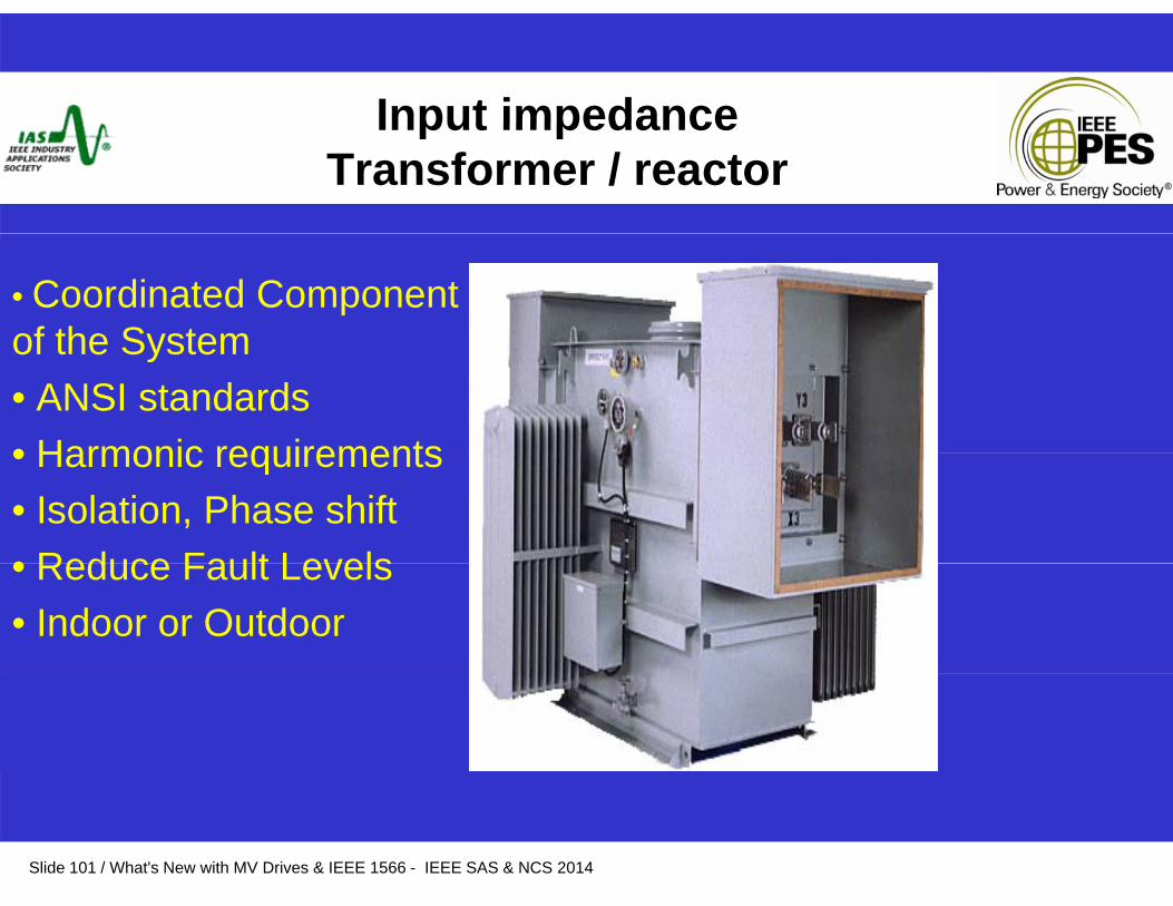
Input impedanceInput impedanceTransformer / reactor
• Coordinated Component of the Systemof the System• ANSI standards• Harmonic requirements• Harmonic requirements• Isolation, Phase shift• Reduce Fault Levels• Reduce Fault Levels• Indoor or Outdoor
Slide 101 / What's New with MV Drives & IEEE 1566 - IEEE SAS & NCS 2014
Cooling
• Air or Liquid CoolingR d d ti l f i d• Redundancy - optional on fans, required on pumps
• Single failure alarms; Second failure shuts down• Alarms and shutdowns for heat sink over-temperature.Alarms and shutdowns for heat sink over temperature.• Fans / pumps automatically switch a minimum of every 30 days
without requiring a shutdown• L10 bearing life of at least 50 000 hours.
Slide 102 / What's New with MV Drives & IEEE 1566 - IEEE SAS & NCS 2014
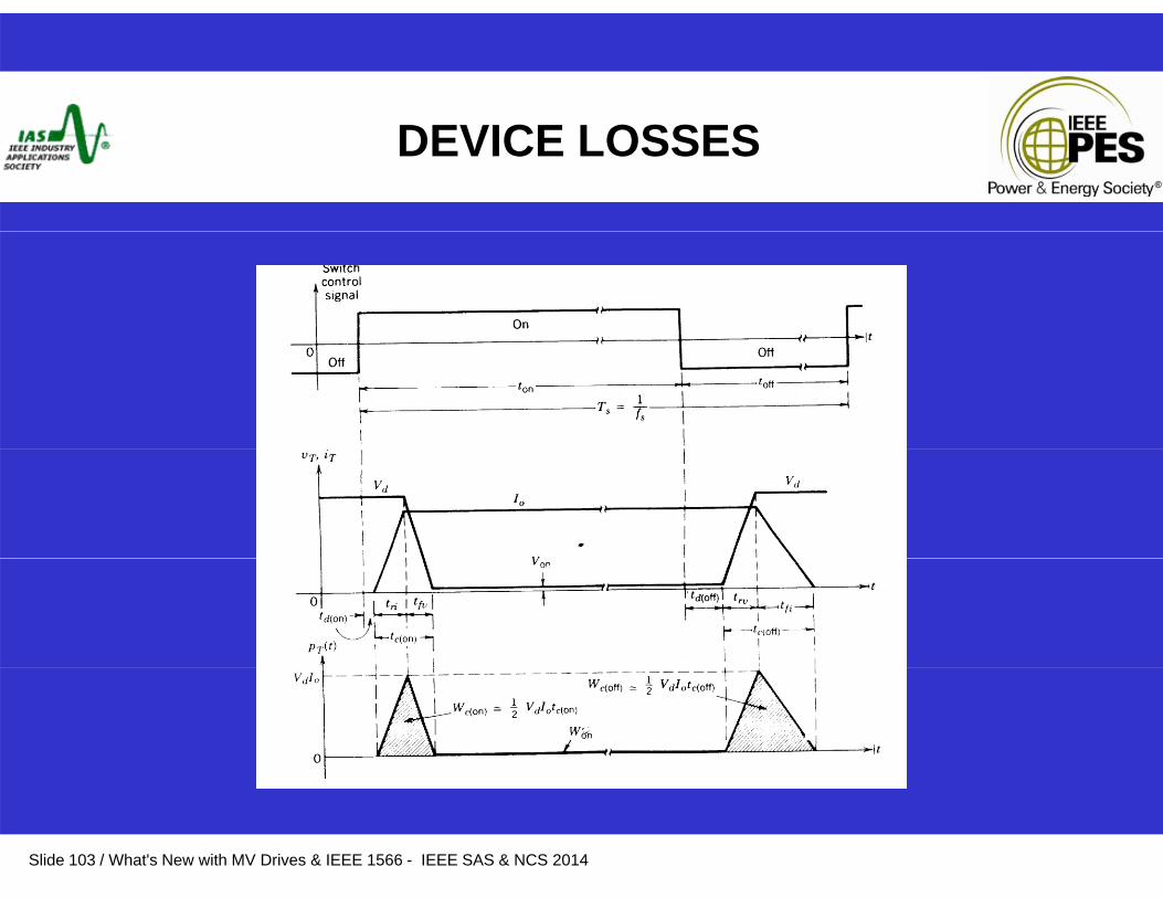
DEVICE LOSSES
Slide 103 / What's New with MV Drives & IEEE 1566 - IEEE SAS & NCS 2014

Switchgear & starters
Should be included in ASD supplier scope
Mechanical and electrical interlocking to be defined by ASD supplier if not in scope
Applicable ANSI/IEEE standards are referenced
Slide 104 / What's New with MV Drives & IEEE 1566 - IEEE SAS & NCS 2014
Motor
• API 541 (Induction) and API 546 (Synchronous)
• Diamond Bullets in API
• Effect of harmonics, voltage stresses – long motor life
• NEMA MG-1 Sections 30 and 31 has useful data
Slide 105 / What's New with MV Drives & IEEE 1566 - IEEE SAS & NCS 2014
Motor
• Consider effect of reduced cooling at lower operating speedsoperating speeds
S h hi fi ld it ti• Synchronous machines field excitation
• Hazardous Locations
Slide 106 / What's New with MV Drives & IEEE 1566 - IEEE SAS & NCS 2014
Documentation
Drawings must conform to local requirementsSymbols, etc.
Typical approval process describedTypical approval process described Final documentation
Storage and maintenance instructionsOperating instructionsOperating instructionsProject drawingsComplete list of renewal partsRecommended spare partseco e ded spa e pa sTest reports System studies
Slide 107 / What's New with MV Drives & IEEE 1566 - IEEE SAS & NCS 2014
Availability, Service and Support
System design shall provide– 20 year service life– 5 year continuous operation
• L10 life on cooling fan of 5 years +• Identify any redundancy requirements
20 i lif l h ld b il bl– 20 year service life plan should be available• Spare parts – identify components requiring replacement over 20
years • TrainingTraining • Service support• Provide expected MTBF and MTTR
There may be a point where replacement with new technology is more practical
Slide 108 / What's New with MV Drives & IEEE 1566 - IEEE SAS & NCS 2014
HAZARDOUS LOCATIONS & MOTORS
• DRIVES INCREASE HEAT GENERATION SLIGHTLY (HARMONICS ON ROTOR)SLIGHTLY (HARMONICS ON ROTOR)
• HEAT DISSIPATION FROM SHAFT MOUNTED FANS IS REDUCED AT LOWER SPEEDSFANS IS REDUCED AT LOWER SPEEDS
• CAN GIVE SLIGHT ROTOR TEMPERATURE INCREASEINCREASE
• AVAILABLE DATA SHOWS SELDOM A CONCERN• IEEE 1349 HAS EXTRA DATAIEEE 1349 HAS EXTRA DATA
Slide 109 / What's New with MV Drives & IEEE 1566 - IEEE SAS & NCS 2014
HAZARDOUS LOCATIONS ANDHAZARDOUS LOCATIONS AND VOLTAGES
• ALL DRIVES GENERATE “COMMON MODE VOLTAGE” (CMV) TO SOME EXTENT(CMV) TO SOME EXTENT
• NEUTRAL POINT IS DISPLACED FROM ZERO• MAGNITUDE DEPENDS ON DRIVE TOPOLOGY• STATOR WINDING VOLTAGES ARE DISPLACED FROM
ZERO• THE ROTOR BUILDS UP A CHARGE TYPICALLY ABOUT• THE ROTOR BUILDS UP A CHARGE TYPICALLY ABOUT
10% OF STATOR CMV (DEPENDS ON MOTOR CONFIGURATION)ENERGY STORED ON ROTOR• ENERGY STORED ON ROTOR
Slide 110 / What's New with MV Drives & IEEE 1566 - IEEE SAS & NCS 2014
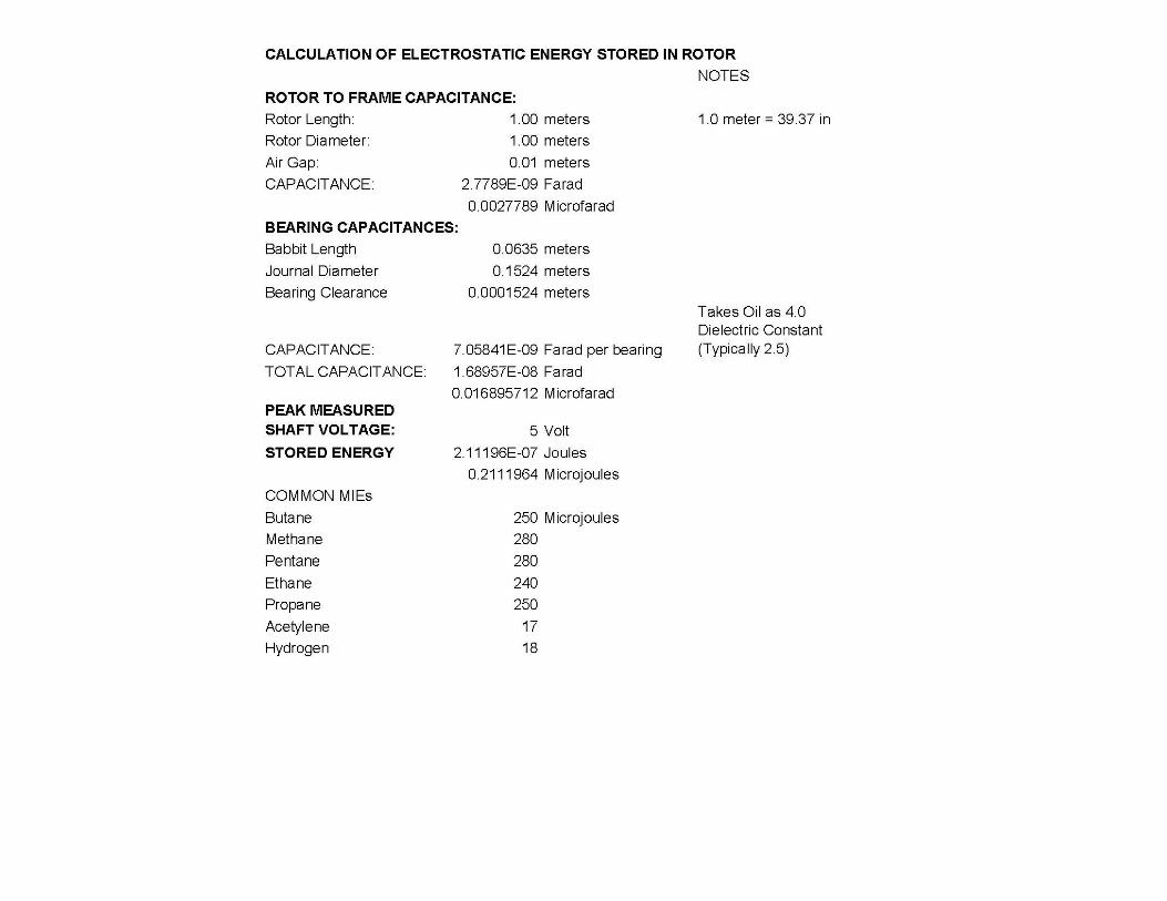
ROTOR ENERGY
ROTOR CAPACITANCE TO FRAME CROTOR VOLTAGE VROTOR VOLTAGE V
ENERGY = ½ CV2ENERGY ½ CV
CAN IT IGNITE EXPLOSIVE MIXTURES?
Slide 111 / What's New with MV Drives & IEEE 1566 - IEEE SAS & NCS 2014
H T R d R t RiHow To Reduce Rotor Rise
Copper Bars Rather Than Aluminum“Open” Construction Higher Number Of PolesOptimize Rotor Bar Shape ForOptimize Rotor Bar Shape For
InverterDucted RotorL Sli
Slide 112 / What's New with MV Drives & IEEE 1566 - IEEE SAS & NCS 2014
Low Slip
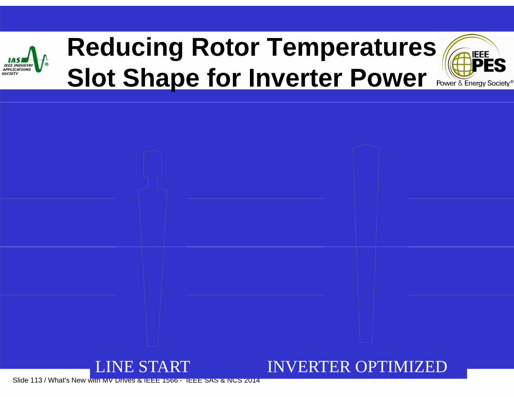
Reducing Rotor TemperaturesReducing Rotor Temperatures Slot Shape for Inverter Power
Slide 113 / What's New with MV Drives & IEEE 1566 - IEEE SAS & NCS 2014LINE START INVERTER OPTIMIZED
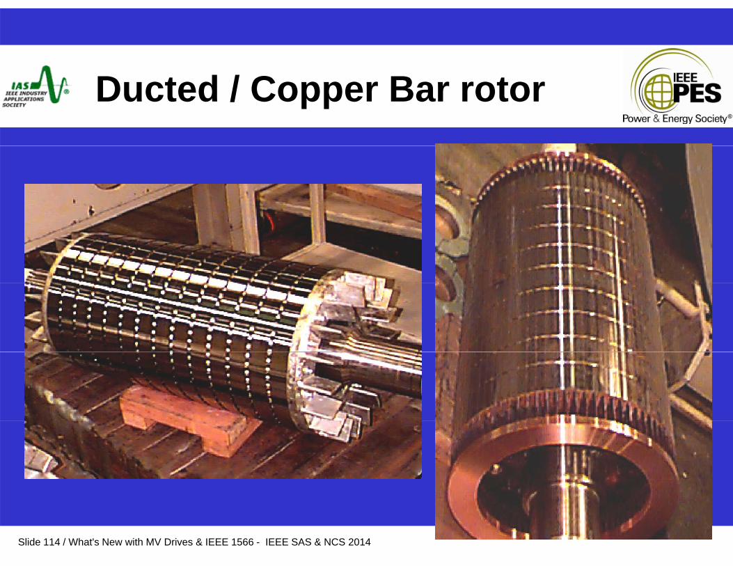
D t d / C B tDucted / Copper Bar rotor
Slide 114 / What's New with MV Drives & IEEE 1566 - IEEE SAS & NCS 2014
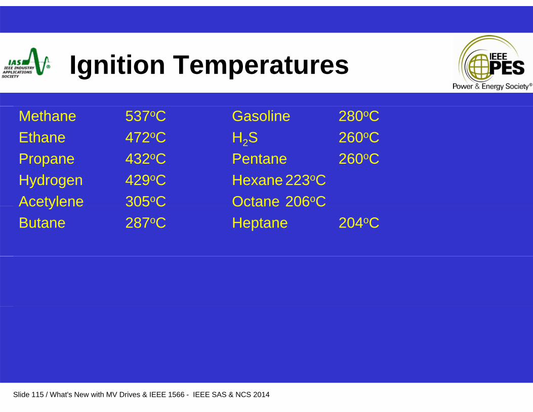
I iti T tIgnition Temperatures
Methane 537oC Gasoline 280oCEthane 472oC H2S 260oCPropane 432oC Pentane 260oCPropane 432oC Pentane 260oCHydrogen 429oC Hexane 223oCAcetylene 305oC Octane 206oCAcetylene 305 C Octane 206 CButane 287oC Heptane 204oC
Slide 115 / What's New with MV Drives & IEEE 1566 - IEEE SAS & NCS 2014
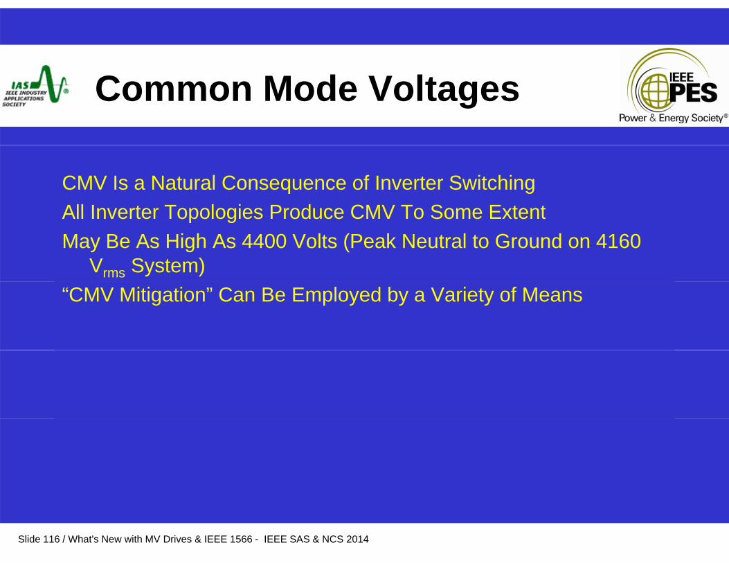
C M d V ltCommon Mode Voltages
CMV Is a Natural Consequence of Inverter SwitchingAll Inverter Topologies Produce CMV To Some ExtentAll Inverter Topologies Produce CMV To Some ExtentMay Be As High As 4400 Volts (Peak Neutral to Ground on 4160
Vrms System)“CMV Mitigation” Can Be Employed by a Variety of Means
Slide 116 / What's New with MV Drives & IEEE 1566 - IEEE SAS & NCS 2014

Testing – Factory & Combined
• Thorough Factory Testing is VitalB i D i• Burn in Devices
• HipotF ll C t d V lt H t R• Full Current and Voltage Heat Run
• Test all Auxiliaries• Test Motor Separately, and on Drive where Practical
Slide 118 / What's New with MV Drives & IEEE 1566 - IEEE SAS & NCS 2014
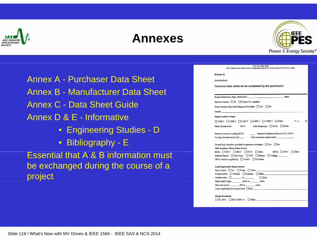
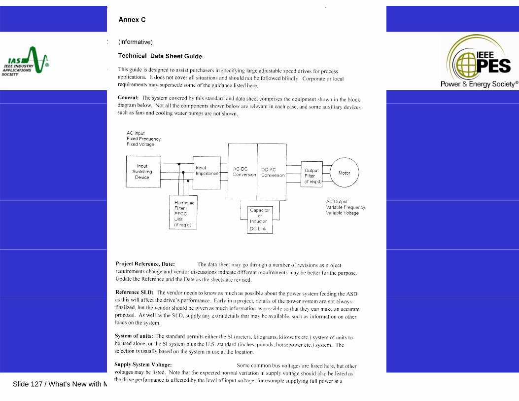
Annexes
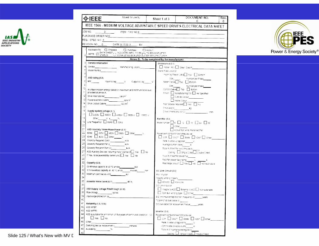
Annex A - Purchaser Data Sheet Annex B - Manufacturer Data SheetAnnex B - Manufacturer Data SheetAnnex C - Data Sheet GuideAnnex D & E - Informative
• Engineering Studies - D • Bibliography - E
& fEssential that A & B information must be exchanged during the course of a project
Slide 119 / What's New with MV Drives & IEEE 1566 - IEEE SAS & NCS 2014
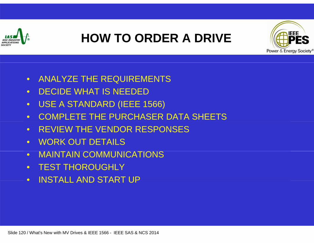
HOW TO ORDER A DRIVE
• ANALYZE THE REQUIREMENTS• DECIDE WHAT IS NEEDED• DECIDE WHAT IS NEEDED• USE A STANDARD (IEEE 1566)• COMPLETE THE PURCHASER DATA SHEETS• REVIEW THE VENDOR RESPONSES• WORK OUT DETAILS
CO C O S• MAINTAIN COMMUNICATIONS• TEST THOROUGHLY• INSTALL AND START UP• INSTALL AND START UP
Slide 120 / What's New with MV Drives & IEEE 1566 - IEEE SAS & NCS 2014

Ask for What You Need
Use a SpecificationIEEE 1566Complete the Data Sheet!
Slide 121 / What's New with MV Drives & IEEE 1566 - IEEE SAS & NCS 2014
Check That You Get WhatCheck That You Get What You Need
Review Vendor’s Data SheetAsk QuestionsTest at Factory Test at SiteTest at Site
Slide 122 / What's New with MV Drives & IEEE 1566 - IEEE SAS & NCS 2014

Training and Startup
Train the Owner’s PeopleDo a Thorough Startup
Slide 123 / What's New with MV Drives & IEEE 1566 - IEEE SAS & NCS 2014
IEEE 1566 DATA SHEETS
PURCHASER DATA SHEETSVENDOR DATA SHEETSDATA SHEET GUIDE
Slide 124 / What's New with MV Drives & IEEE 1566 - IEEE SAS & NCS 2014
Slide 125 / What's New with MV Drives & IEEE 1566 - IEEE SAS & NCS 2014

Slide 126 / What's New with MV Drives & IEEE 1566 - IEEE SAS & NCS 2014
Slide 127 / What's New with MV Drives & IEEE 1566 - IEEE SAS & NCS 2014

IEEE 1566 DATA SHEETSIEEE 1566 DATA SHEETS
VENDOR DATA SHEET
REVIEW THIS!REVIEW THIS!
Slide 128 / What's New with MV Drives & IEEE 1566 - IEEE SAS & NCS 2014

DATA SHEETS
ESSENTIAL FOR GETTING WHAT YOU NEED WITHOUT
CONFUSIONCONFUSION
COMMUNICATION!COMMUNICATION!
Slide 129 / What's New with MV Drives & IEEE 1566 - IEEE SAS & NCS 2014
TEST THOROUGHLY
• COMPLETE FACTORY TESTSSOLVE PROBLEMS IN THE FACTORY RATHER• SOLVE PROBLEMS IN THE FACTORY RATHER THAN ON SITE
• LOAD TEST• LOAD TEST• CONTROL TESTS
AUXILIARIES• AUXILIARIES• THOROUGH STARTUP
TRAIN PEOPLE• TRAIN PEOPLE• MAINTAIN PROPERLY
Slide 130 / What's New with MV Drives & IEEE 1566 - IEEE SAS & NCS 2014
Summary
• Adjustable Speed Drives have become common place• Adjustable Speed Drives have become common place• Increased use is due to the need for energy savings and other
benefits which these controllers bring to all industries and a wide variety of applications
• Numerous drive choices currently in the marketplace• IEEE 1566 has been created to assist users in specifying equipment• IEEE 1566 has been created to assist users in specifying equipment
on the basis of performance• Recommend that you become familiar with this standard• Standard must use the data sheets• IEEE 1566 is a living document which is reviewed and updated
regularlyregularly– Must be maintained by users through IEEE– Get involved
Slide 131 / What's New with MV Drives & IEEE 1566 - IEEE SAS & NCS 2014

WHATS NEW IN MV DRIVES
THANK YOUTHANK YOU
Slide 132 / What's New with MV Drives & IEEE 1566 - IEEE SAS & NCS 2014