woodenhaptics: a starting kit for crafting force...
TRANSCRIPT

WoodenHaptics: A Starting Kit for CraftingForce-Reflecting Spatial Haptic Devices
Jonas ForsslundRoyal Institute of Technology
Stockholm, [email protected]
Michael YipStanford UniversityStanford, CA, USA
Eva-Lotta SallnasRoyal Institute of Technology
Stockholm, [email protected]
ABSTRACTSpatial haptic interfaces have been around for 20 years. Yet,few affordable devices have been produced, and the designspace in terms of physical workspace and haptic fidelity ofdevices that have been produced are limited and discrete.In this paper, an open-source, open-hardware module-basedkit is presented that allows an interaction designer with littleelectro-mechanical experience to manufacture and assemble afully working spatial haptic interface. It also allows for mod-ification in shape and size as well as tuning of parameters tofit a particular task or application. Results from an evaluationshowed that the haptic quality of the WoodenHaptics devicewas on par with a Phantom Desktop and that a novice couldassemble it with guidance in a normal office space. This opensource starting kit, uploaded free-to-download online, affordssketching in hardware; it “unsticks” the hardware from beinga highly-specialized and esoteric craft to being an accessibleand user-friendly technology, while maintaining the feel ofhigh-fidelity haptics.
Author KeywordsGuides; do-it-yourself; open-source; open-hardware; spatialhaptics; force-feedback; haptic device; hardware sketching;interaction design
ACM Classification KeywordsH.5.2. Information Interfaces and Presentation (e.g. HCI):User Interfaces (D.2.2, H.1.2, I.3.6) Haptic I/O
PART I: INTRODUCTIONSpatial haptic interfaces are grounded human interface de-vices that track a physical manipulandum (handle) in space,and provides the means of reflecting a directional force onthat manipulandum and consequently the user. With the de-vice and appropriate haptic rendering algorithms, an end-usercan explore a virtual environment through virtual couplingbetween the manipulandum’s position and a representativeavatar [24]. As more applications have 3D user interfaces[1], spatial haptics becomes increasingly useful for feeling
Permission to make digital or hard copies of all or part of this work for personal orclassroom use is granted without fee provided that copies are not made or distributedfor profit or commercial advantage and that copies bear this notice and the full cita-tion on the first page. Copyrights for components of this work owned by others thanACM must be honored. Abstracting with credit is permitted. To copy otherwise, or re-publish, to post on servers or to redistribute to lists, requires prior specific permissionand/or a fee. Request permissions from [email protected] 2015, January 15–19, 2015, Stanford, California, USA.Copyright is held by the owner/author(s). Publication rights licensed to ACM.ACM 978-1-4503-3305-4/15/01 ...$15.00.http://dx.doi.org/10.1145/2677199.2680595
Figure 1. The completed wooden haptics device.
the shapes of occluded objects, collisions, object stiffness andinertias, surface textures, and so on [24]. While vibrotactilehaptics are ubiquitous in all cellular phones, the 3D force-displaying counterparts, spatial haptics, are not as widelypresent. Devices for spatial haptics have been used for sur-gical simulation [3], physical rehabilitation [2] and for handtool guidance [9]. Applications in other domains could ben-efit from including spatial haptics, but this requires finding agood match between the qualities of the device employed andthe application. The common devices commercially available(Figure 2) represent only a limited design space in terms offidelity, price and capabilities (e.g. workspace dimensionsand maximum force). Therefore, application specific deviceshave sometimes been developed, such as for simulation ofmicro-surgical bone drilling [22]. However, engineering ahaptic device is still a large commitment and only feasiblein highly specialized robotics labs that have the mathematicaland mechanical know-how to realize and achieve high qualityhaptics in their design.
Research and advances in haptics tend to be focused on tech-nological refinements and little attention is directed towardsholistic design and aestetics of the devices. As a response tothis, Moussette has proposed the intersection of Design andHaptics as a new field of study [17]. This approach is cen-tered around hands-on workshops [16], exploration, makingand sketching in hardware with simple haptics [18] in orderto get a heightened sensitivity to haptics. The benefits thatfollow from this approach can be extended to spatial haptics.

Figure 2. Common spatial haptic devices. From the left: Novint Falcon, Phantom Desktop (now 3D Systems Geomagic Touch X), Force DimensionOmega, Phantom Omni (now 3D Systems Geomagic Touch), and Phantom Premium 6-DOF (now 3D Systems Geomagic Phantom Premium).
In this paper we introduce a new spatial haptic device that isdesigned and packaged as a kit in a way that a designer can re-configure or re-design it, thus adapting it to different domainsor requirements. This kit, called WoodenHaptics, is designedto provide comparable haptic fidelity to commercial devices.We carefully chose to encapsulate certain technical details(e.g. the electrical system), whereas others are very visible(the mechanical structure and wire rope power transmission);this is intended to help designers focus more on designingfor their application rather than problem solving through me-chanical and electrical nuances and details. Through theseefforts we have reduced the “stickiness” [29] of constructingspatial haptic devices to a level where a designer can design,create, assemble and modify their own version of the device.We evaluated its ease of adoption on non-specialists and first-time builders (under guidance) to show that it provides a valu-able medium for “hardware sketching” in spatial haptics.
BackgroundWith the advent of Massie’s [10] force-reflecting device in1993, spatial haptics as a multi-purpose human-computer in-teraction interface became popular through the commercial-ized Phantom series [11] still available on the market to-day (figure 2). While all these devices can read a spa-tial position and render a directional force back to the userthrough the manipulandum, the experience and quality of theforces/movement is quite different, something that is also re-flected in the price tag that ranges from $300 to over $20,000USD. Other devices with equivalent functionality from theuser’s perspective have since appeared, but the market is farfrom being as diverse as that of computer mice and joysticks.
A great deal of fundamental theory for building a haptic de-vice has been described in e.g. [7] and [6]. However, bridgingthe gap from reading the fundamentals to constructing a fully-functional 3D spatial haptic device of the prototypical Phan-tom [10, 11] is still a daunting task to a common interactiondesigner and is only feasible for an expert roboticist. Muchpractical and tacit knowledge is required to actually make ahigh-fidelity haptic device, since it relates to making a correctcombination of design choices, ranging from which type of
motors, what mechanical structure, which control paradigmand even which type of screws to choose. Then the partsneed to be located and purchased, which can be very time-consuming and confusing. Furthermore, the robotics litera-ture describing the mathematics required to operate the hapticdevice [7, 4] might be overwhelming in scope and content tothe electro-mechanical novice.
Kits and Tools for DesignKits and tools for design through making and crafting is anactive research area in TEI/HCI [5, 8, 13, 14, 25, 26]. Phid-gets [5] is used to simplify development of physical interfacesthrough providing “everyday programmers” with a kit of pre-made electronic physical widgets. Toolkits have been de-scribed as particularily instrumental to sketching in hardware[19]. Software tools have been developed explicitly targetingdesigners without production training in electronics [8] andfurniture design [26]. Even the notion of an “untoolkit” hasbeen proposed as a conceptual tool to leverage existing stan-dard materials and components in new artifacts [14]. Opensource hardware designed for personal fabrication has beendescribed as an approach to support design of different as-pects of electronic products, since the designer only has tomodify those parts of the design pertinent to the designers in-terest and still get a working product [13]. Other kits such asthe Hapkit [15] is constructed with goal of teaching engineer-ing concepts per se through hands-on experience [21, 27].
In this paper, WoodenHaptics is presented as an open source“starting kit” for material exploration, design and realizationof application specific force reflecting haptic devices. Thisdistinguishes our kit from a toolkit where combinations ofprovided parts yield many designs (we only provide one ref-erence design in the kit itself), and an untoolkit where noneof the modules from the kit goes into the final design. Theintended audiences for the kit are interaction design studiosand HCI researchers, especially for cases where applicationsrequire different form factors (e.g. length of arms), and otherproperties (e.g. maximum force) that off-the-shelf deviceswon’t meet, something we in our own practice have seen aneed for. Our primary aim is to support professional design

Figure 3. The parts needed to be assembled by user: the base driving the body A, that in turn drives body B and, indirectly through C’, body C.
exploration of the interaction qualities that follows from mod-ifications of the reference design. A high-quality spatial hap-tic interface requires careful attention to its computational andphysical materials, which can only be experienced as a wholewith a fully assembled device. Therefore, a designer who de-cides to deepen her engagement beyond software will have toset up a workbench for explorations. WoodenHaptics servesas a complete kit for starting such explorations.
PART II: KIT DESCRIPTION AND USAGEA pair of interaction design researchers without training inmechanical engineering were provided with the kit consistingof a complete set of hardware components that make up a fullspatial haptic device. This included all the pre-cut plywoodparts, screws, bearings and all other mechanical components(Figure 4). The kit came with three motors (Maxon RE40)with pre-mounted encoders, and an electronics box (Figure5) that connects to a 48V lab power supply and a standardPC equipped with a Data Acquisition interface (DAQ, Sen-soray S826). The kit requires only a limited set of tools:hex keys, a steel wire crimping tool and snippers, a torchand an arbor press (Figure 8); a list of these tools and whereto purchase them are available online. Software required tooperate the device was included as well. Thus, the buildercan immediately run available demo programs and proceedto application-specific development.
Figure 4. The parts included in the kit. Not shown here are the threemotors, electrical cables and the electronics box (Figure 5), and config-urable software that completes the kit.
AssemblyThe entire structural pieces are manufactured from a laser cut-ter out of 6 mm (or approximately 1/4 inch) plywood. Toform stiff three-dimensional parts from the flat sheets, severallayers are stacked and held together with screws. All holes inthe plywood parts are adjusted with sub-millimeter precisionsuch that all screws can self-tap (self-thread) the holes, allow-ing for quick assembly and disassembly. Stacked parts arealigned by inserting dowel pins (precision cylindrical pins)with an arbor press before adding screws. Bearings are press-fit as well using the arbor press. In fact, there is no use ofbondants or adhesives, resulting in a visually and mechani-cally clean, quickly disassemble-able and reconfigurable de-vice. The kit comes with instructions on how to assemble themain bodies, as well as video documentation.
The bodies A, B and C (figure 3) form the three links or de-grees of freedom (DOF) that together enable the tip of the de-vice (P in figure 6) to be moved left/right, up/down and in/out.Each DOF is coupled independently to a motor through wirerope. The angle of each DOF is a fixed ratio to the rotation ofthe motor shaft, and therefore the angles are measured by theencoders mounted on each motor (figure 5).
Figure 5. The first degree of freedom motor connected with power andencoder wires to the electrical interface. The close-up view shows thealuminum capstan and wire rope coupling.
CablingThe kit utilizes cable drive for all its transmissions: a strongsteel wire rope transmits the power from each motor to itsown respective link. Figure 5 shows a standard cable drive

transmission used in all degrees of freedom. The motor shaftis attached to the capstan, which is a shaft for a cable to wraparound and grip. The cable makes 5 wraps around the capstanand is terminated at both ends. The cable needs to be taut togrip the capstan, which is done at the termination by eithertightening or loosening a screw. For the last link, a turnbuckleis used to maintain a taut cable. Now, for each body, when thecapstan is rotated with the cable gripped firmly to it, the bodyis then rotated; alternately, when the body is rotated, the cap-stan is subsequently rotated. This completes the transmissionassembly, allowing for the motors and the driven axis to notrequire collocation. This allows for gearing up of the motortorques for achieving larger forces without using gearboxes,as well for easy replacement of motors. The reasons for thesedesign choices are further discussed in Part III.
Electrical systemThe kit comes with three high-quality motors, each driving arespective degree of freedom. The designer only has to con-nect the encoder to the electronics box (that routes them to thecomputer), and each motor power cable to respective outputof the electronics box (figure 5). Two ribbon cables connectsthe electronics box with the Sensoray S826 board on the PC.
The motors chosen are more powerful than is common in thedevices pictured in figure 2. They are specified for allow-ing a max continuous current of 3.16A safely, and we havelimited the maximum current to 3 ampere. This means thatthe user will not have to worry about electrical heat, burning,etc, which is the case when the motors are overdriven in shortperiods of time, which is common practice otherwise.
Software ConfigurationThe kit is complete with a working open-source softwaremodule for the mechanical design that comes with the kit.If a dimension have been changed by the user or tuning ofthe experience is desired, the user can easily modify a vari-able in a text file to represent this change. The variables ofinterest to change are: the diameter of each capstan and body,the length of each link and the mass and mass center of eachbody. This effectively is equivalent to changing the gearingof the motor, and changing the size of the workspace, respec-tively. The design also affords the easy replacement of motorswith different motors, but the user will then need to adjustthe torque/current ratio as defined by their motor datasheet.The maximum stiffness and damping of the complete devicecan be found retroactively by experimenting and adjusting thevalues accordingly.
PART III: FUNDAMENTALS AND THEORYThis section describes how the kit was developed and thedesign principles/considerations involved. We cover herebriefly, the mechanical structure, the kinematics and controltheory applied and why certain design decisions were madeto support easy user fabrication and modification in partic-ular. We are knowingly only addressing one kind of me-chanical structure (the serially linked) and one control type(impedance control). Alternatives are parallel mechanicalstructure like e.g. Novint Falcon, and admittance control [28]that requires force sensing.
Haptic fidelity and transparencyThe power transmission of a haptic device is a critical com-ponent that needs to be designed carefully as it transmits theforces and velocities from software to the hand of the user.Haptic fidelity is achieved by having transparency in the sys-tem – that is, desired forces and velocities defined in softwareaccurately match forces and velocities delivered to the user.Three major contributions that reduce the transparency of asystem is friction (resulting in diminished haptic perception),backlash (resulting in chatter in the motors and the device),and physical compliance (resulting in a loss of ability to per-ceive stiff environments).
Although motor and gearbox combinations are commerciallymuch more common, cable drive transmission is the stan-dard for haptic devices because it provides a near friction-less transmission and has no backlash, which no gearbox canachieve. The choice of cable is also an important factor: a ca-ble with high flexibility will provide greater transparency asthe users will not percieve the forces required to “bend” and“unbend” the cable as the capstan rolls. Therefore, uncoatedstainless steel cables with high count of individual steel fibers(we use a cable of 0.54 mm diameter, with fibers in a 7 × 7configuration, more is recommended if available) present aviable option. The grip of the cable on the capstan increasesexponentially as the cable wraps around, and therefore evena few turns will immediately prevent the cable from slipping.In practice, 5 turns is more than enough to prevent any slip-ping between the capstan and the cable. This principle is alsohow the final link’s cable transmission (using the cable loopand turnbuckle) works without slipping.
Figure 6. The device is a serially linked mechanism, where the angle ofA, B and C uniquely defines point P in the base reference frame N.
Another major design choice for achieving high haptic fi-delity was to mount the second and third axis motors on bodyA (figure 6). This choice is highlighted by three intentionalbenefits: the simplified and shorter cable routing affords bet-ter transparency in the system, placement of the motors allowfor easy access, removal, and installation for other motors ofdifferent sizes, and shorter cable routing reduces the chance
of the transmission de-cabling. Failure in the cable transmis-sion (e.g. cable snap or comes loose) is thereby localized toits own small section of the device, while allowing for the restof the device to remain in working order.
The third major contribution to achieving transparency in thesystem is having a physically stiff device. Increasing stiffness(ie. reducing compliance) in the device’s structure is doneby increasing the second moment of inertia of each link (e.g.making link wider so they do not twist), improving the jointstiffnesses (e.g. by increasing shaft diameters, increasing dis-tance between shaft bearings that hold the shafts straight), andusing a stiff material. Because plywood is a layered compos-ite, it is in fact quite stiff and yet still reasonably light; it isalso soft enough for self-tapping holes and very minor mis-alignments that all contribute to making the device more ac-cessible and forgiving to build, without sacrificing substantialhaptic fidelity.
Finally, each motor to capstan combination is connected thr-ough a flexible shaft coupler, which acts to not only reducefriction caused by misalignments in the axes of the motor andthe capstan, but also serves as an easy way to swap out differ-ent motors and find the best motor for an application withoutperforming any disassembly of the cable transmission. Thisserves to promote hardware sketching on the actuator side.
Mathematical description and analysisIn order for the spatial haptic interface to be useful, the posi-tion of the user’s hand and thus the end-effector of the devicemust be known in space. This is achieved by measuring theangle of the motor shafts using encoders, and doing the for-ward kinematics to map motor angles to cartesian-space po-sition. Below we provide only a very brief overview of themathematics involved in achieving haptic feedback; all thedetails regarding the position and force mappings discussedin this section are derived from [4] using standard techniquesfor robot manipulators.We derive the manipulandum positionthrough forward kinematics, which in this case is a classic’RRR’ configuration manipulator; that is, it has three mov-ing links which are serially-linked through revolute(R) joints(figure 6), and can be calculated as follows:
Px =Py =Pz =
cos θa(Lb sin θb + Lc cos(θb + θc))sin θa(Lb sin θb + Lc cos(θb + θc))
Lb cos θb − Lc sin(θb + θc)(1)
where L is the length of each body to the next and θa,b,c arethe angles of respective body. To give a force F at the manip-ulandum, the body torque τ is computed as:
τ = J>F, (2)
where J is called the Jacobian matrix, and is the first par-tial derivative of the forward kinematics (1) with respect tothe body angles θ [4]. A final necessity to account for is theweight of the manipulandum: without compensating for themanipulandum weight, the user will have to hold up the de-vice’s weight in their hands. To compensate for gravity, theweights of the three links as well as their centers of gravityare estimated, and motor torques to counter gravity forces areapplied. For ease of use, the kit’s software module allow for
tuning of the link parameters while masking the mathematicsinvolved to solve for force, position, and gravity.
Electrical systemThe electrical system has two purposes: to drive the motorsand to measure their angular position. The torque of the mo-tor used is proportional to the current that is driven throughit, not the voltage it is supplied. Therefore a current or torquecontroller (in our case Maxon ESCON 50/5) is connected be-tween a generic power supply and the motor.
It is worth mentioning that the components used (motors, am-plifiers, encoders and acquisition card) are of professional labquality and should not be confused with hobbyist counter-parts. While efforts to replace them with lower cost alterna-tives are very welcome, one has to be careful in preserving theprecision needed. For example, the delay has to be less than 1ms and the resolution and quality of D/A converter sufficient[23]. However, this also brings to the surface the potentials ofthis starting kit, as it allows users to explore what their haptictolerance is for lower-cost alternatives.
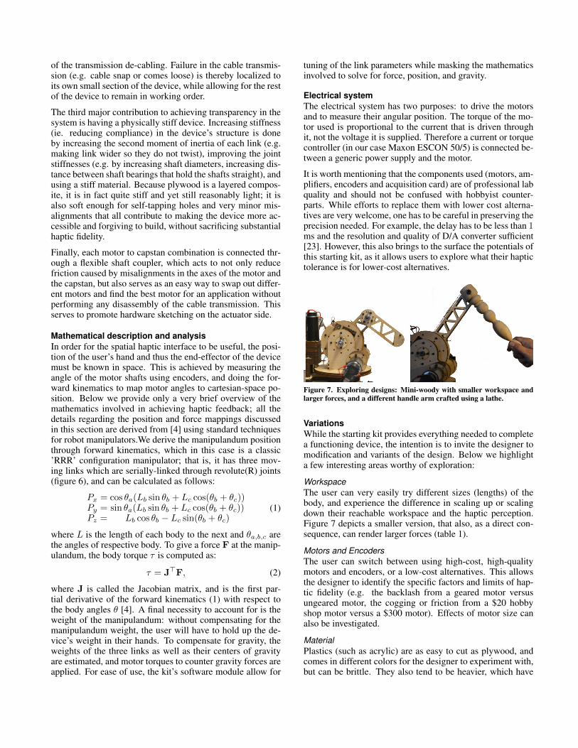
Figure 7. Exploring designs: Mini-woody with smaller workspace andlarger forces, and a different handle arm crafted using a lathe.
VariationsWhile the starting kit provides everything needed to completea functioning device, the intention is to invite the designer tomodification and variants of the design. Below we highlighta few interesting areas worthy of exploration:
WorkspaceThe user can very easily try different sizes (lengths) of thebody, and experience the difference in scaling up or scalingdown their reachable workspace and the haptic perception.Figure 7 depicts a smaller version, that also, as a direct con-sequence, can render larger forces (table 1).
Motors and EncodersThe user can switch between using high-cost, high-qualitymotors and encoders, or a low-cost alternatives. This allowsthe designer to identify the specific factors and limits of hap-tic fidelity (e.g. the backlash from a geared motor versusungeared motor, the cogging or friction from a $20 hobbyshop motor versus a $300 motor). Effects of motor size canalso be investigated.
MaterialPlastics (such as acrylic) are as easy to cut as plywood, andcomes in different colors for the designer to experiment with,but can be brittle. They also tend to be heavier, which have
to be supported with more motor torque for gravity compen-sation. Aluminum is lightweight and stiff, but needs to becut using special equipment (warter-jet cutter) and requiresthreading holes separately. Solid and composite wood choicecan provide different stiffness and weight tradeoffs. Physi-cal stiffness, the inertia of the device, and even Visual appealcan be explored by using different materials. Figure 7 showsa variant where one part is hand-fabricated from solid woodusing a lathe.
Add-onsA user may add buttons, sensors or even vibrotactile actuatorson the manipulandum, which can further improve perceptionof textures [12]. Different grips or end-attachments that inter-face with the user can be explored.
PART IV: EVALUATIONThree aspects of the reference design and starting kit wereevaluated. First, to what extent could someone withoutrobotics training or access to a sophisticated lab use the kit,assemble the device and make it work? Second, how does thedevice compare to commercially-produced haptic devices?And finally, what are the technical properties?
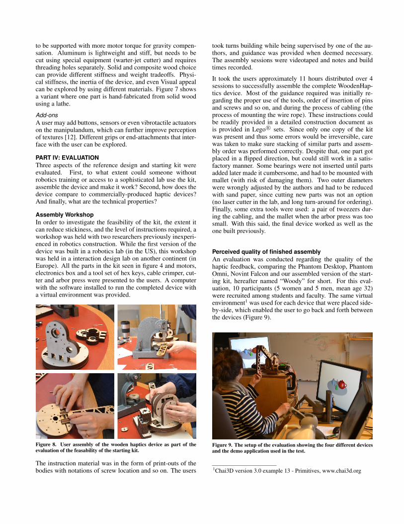
Assembly WorkshopIn order to investigate the feasibility of the kit, the extent itcan reduce stickiness, and the level of instructions required, aworkshop was held with two researchers previously inexperi-enced in robotics construction. While the first version of thedevice was built in a robotics lab (in the US), this workshopwas held in a interaction design lab on another continent (inEurope). All the parts in the kit seen in figure 4 and motors,electronics box and a tool set of hex keys, cable crimper, cut-ter and arbor press were presented to the users. A computerwith the software installed to run the completed device witha virtual environment was provided.
Figure 8. User assembly of the wooden haptics device as part of theevaluation of the feasability of the starting kit.
The instruction material was in the form of print-outs of thebodies with notations of screw location and so on. The users
took turns building while being supervised by one of the au-thors, and guidance was provided when deemed necessary.The assembly sessions were videotaped and notes and buildtimes recorded.
It took the users approximately 11 hours distributed over 4sessions to successfully assemble the complete WoodenHap-tics device. Most of the guidance required was initially re-garding the proper use of the tools, order of insertion of pinsand screws and so on, and during the process of cabling (theprocess of mounting the wire rope). These instructions couldbe readily provided in a detailed construction document asis provided in Lego R© sets. Since only one copy of the kitwas present and thus some errors would be irreversible, carewas taken to make sure stacking of similar parts and assem-bly order was performed correctly. Despite that, one part gotplaced in a flipped direction, but could still work in a satis-factory manner. Some bearings were not inserted until partsadded later made it cumbersome, and had to be mounted withmallet (with risk of damaging them). Two outer diameterswere wrongly adjusted by the authors and had to be reducedwith sand paper, since cutting new parts was not an option(no laser cutter in the lab, and long turn-around for ordering).Finally, some extra tools were used: a pair of tweezers dur-ing the cabling, and the mallet when the arbor press was toosmall. With this said, the final device worked as well as theone built previously.
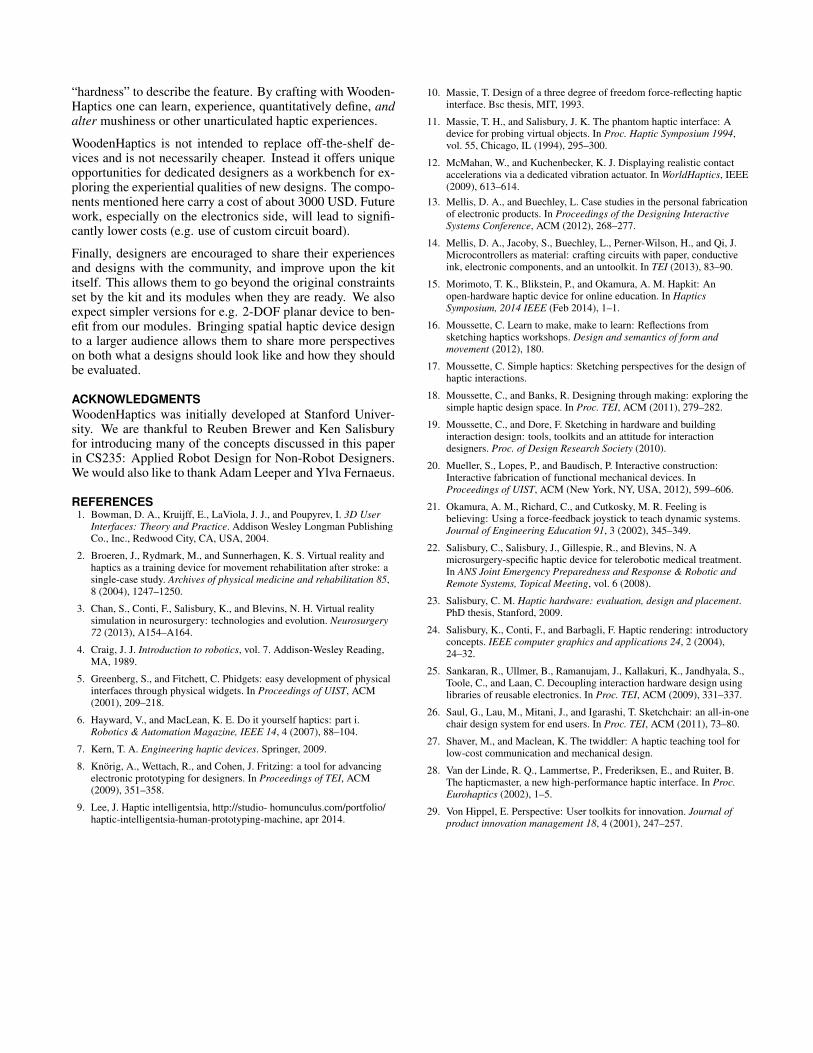
Perceived quality of finished assemblyAn evaluation was conducted regarding the quality of thehaptic feedback, comparing the Phantom Desktop, PhantomOmni, Novint Falcon and our assembled version of the start-ing kit, hereafter named “Woody” for short. For this eval-uation, 10 participants (5 women and 5 men, mean age 32)were recruited among students and faculty. The same virtualenvironment1 was used for each device that were placed side-by-side, which enabled the user to go back and forth betweenthe devices (Figure 9).
Figure 9. The setup of the evaluation showing the four different devicesand the demo application used in the test.
1Chai3D version 3.0 example 13 - Primitives, www.chai3d.org

The evaluation consisted of two parts. The participants firsttask was to rate the experienced quality of the haptic feed-back using the devices one at a time. Experienced qualitywas evaluated in a questionnaire using a seven point Likert-type scale with four items asking about to what degree thehaptic feedback felt being of high quality, precise, smoothand distinct. In the analysis, the four items were summedinto one dimension measuring subjective experience of hapticfeedback quality. The questionnaire was filled in after expe-riencing each haptic device respectively. In the second part,participants compared all devices again and reported whichone of the commercial devices they felt most closely matchedthat of Woody in haptic quality on their own terms.
The results, as the average summed ratings (std. dev.) ofeach device was as follows. Desktop 25.8 (2.10), Omni 19.5(5.7), Falcon 11.2 (6.3) and Woody 24.4 (3.37). The partici-pants thus rated Woody’s experience between Phantom andOmni. It resonates with the second part of the evaluationwhen the participants were explicitly asked to draw a line be-tween Woody and the device they thought was most similarto Woody. The results show that 7 of the participants thoughtthat Woody was most similar to the Desktop, 3 reported thatWoody felt the most similar to the Omni.
Changing haptic properties when varying designIn order to demonstrate the ability to modify haptic perfor-mance through design, different versions of the device wereconstructed with the starting kit as a base. Woody (B=20cm, C=22cm) and a “mini” variant (B=10 cm, C=12 cm)were created to explore the trade-off betweeen workspace andforce-feedback properties (Figure 7). Stiffness was empiri-cally tuned at a level where no vibrations was felt while in-teraction were at a maximal stiffness (5 N/mm). The resultsare presented in Table 1. For comparison, maximum forcevalues for Omni and Falcon were added from [22] and fric-tion and workspace measurements were taken for these de-vices as well. A lower bound for the workspace was foundby placing a virtual sphere in the virtual origin and increas-ing its diameter while maintaining that the whole sphere caneasily be touched from the outside. Peak force was found forWoody and Mini-woody by calculating, but not physicallyoutputting, the largest force that could be applied in x, y, andz direction until at least one motor saturates. The workspacewas swept and the lowest value was recorded. Since the mo-tors were specified to handle more than 3 ampere nominallythe continuous force and peak force is the same. Back-drivefriction was measured using a hand-held digital force gauge(FG-5000A-232, Lutron Electronics, Taiwan) slowly movedfrom one side of the workspace (as defined above) to the otherpassing the origin, sideways, inwards and upwards. Ten mea-surements were taken and averaged for each direction and de-vice. Gravity compensation was enabled if available. Omni,which lacked active gravity compensation was supported bya 2 m thin string from the ceiling in sideways and inwardsmeasurements.
This study demonstrated the exploration of trade-offs inchanging workspace dimensions with forces and friction. Thecommercial devices provided the static performance mark for
Woody Mini-w. Omni Falconworkspace 200+ 80+ 100+ 60+peak force 9.9+ 19.0+ 3.3 8.9+cont. force 9.9 19.0 0.88 8.9
friction 0.6/0.7/0.9 0.6/1.0/0.9 0.2/0.4/1.1 1.2/3.6/1.3Table 1. Varying haptic properties through different design changes,and comparison to commercial devices.
which the modified designs were compared against. It canbe seen that there is no one device that provides the largestworkspace, forces, or minimum friction altogether, showingthe strengths and limitations of each design and the benefitfor hardware sketching.
PART VI: DISCUSSIONWe have shown how the WoodenHaptics starting kit can be anengaging spatial haptics device testbed without many of thesticky issues usually involved in the craft. We have further-more demonstrated that high haptic fidelity was achievableusing WoodenHaptics, on par with commercial devices. Foran interaction designer, the WoodenHaptics toolkit serves to:
• help the designer understand the fundamentals of themechanism (e.g. it shows clearly how three motors worktogether to generate one force vector at the end point of themanipulandum).
• enable the designer to incorporate the device into theirown projects quickly and easily without being a electro-mechanical expert.
• enable the designer to explore the user experience (byobjectively changing/tuning certain parameters or replacecomponents such as motors).
• establish a common language between designers and ex-perienced hardware engineers. The designer can now say“can you make a device like this, but smaller?” or “whatcould or needs to change for us to manufacture somethinglike this for our application?”
With WoodenHaptics, a designer can create variations of aserially-linked 3-DOF grounded spatial haptic device. Theconstraints imposed by the kit frees the designer from solv-ing many electrical, computational and mechanical problemssince these have already been solved; it instead allows theuser to innovate in terms of motor choices, workspace di-mensions, physical material, aesthetics and extended func-tions like buttons. As personal fabrication of parts becomeseasier, e.g. through direct interaction with a laser cutter [20]or software tools [26], designers can quickly explore differ-ent variations that can optimize their haptic experience for aparticular application.
Common haptic devices and application programming inter-faces sometimes give wrong expectations of what experiencesthey actually support. For example, Mousette [17] noted that“hardware hard is relative” from his experiments with a com-mercial haptic device where a virtual object specified to beof maximum stiffness still yielded a sensation he refer to as“mushy hard”. It is likely that he would have had a differentexperience with a device equipped with more powerful mo-tors, or if the developers had used another terminology than
“hardness” to describe the feature. By crafting with Wooden-Haptics one can learn, experience, quantitatively define, andalter mushiness or other unarticulated haptic experiences.
WoodenHaptics is not intended to replace off-the-shelf de-vices and is not necessarily cheaper. Instead it offers uniqueopportunities for dedicated designers as a workbench for ex-ploring the experiential qualities of new designs. The compo-nents mentioned here carry a cost of about 3000 USD. Futurework, especially on the electronics side, will lead to signifi-cantly lower costs (e.g. use of custom circuit board).
Finally, designers are encouraged to share their experiencesand designs with the community, and improve upon the kititself. This allows them to go beyond the original constraintsset by the kit and its modules when they are ready. We alsoexpect simpler versions for e.g. 2-DOF planar device to ben-efit from our modules. Bringing spatial haptic device designto a larger audience allows them to share more perspectiveson both what a designs should look like and how they shouldbe evaluated.
ACKNOWLEDGMENTSWoodenHaptics was initially developed at Stanford Univer-sity. We are thankful to Reuben Brewer and Ken Salisburyfor introducing many of the concepts discussed in this paperin CS235: Applied Robot Design for Non-Robot Designers.We would also like to thank Adam Leeper and Ylva Fernaeus.
REFERENCES1. Bowman, D. A., Kruijff, E., LaViola, J. J., and Poupyrev, I. 3D User
Interfaces: Theory and Practice. Addison Wesley Longman PublishingCo., Inc., Redwood City, CA, USA, 2004.
2. Broeren, J., Rydmark, M., and Sunnerhagen, K. S. Virtual reality andhaptics as a training device for movement rehabilitation after stroke: asingle-case study. Archives of physical medicine and rehabilitation 85,8 (2004), 1247–1250.
3. Chan, S., Conti, F., Salisbury, K., and Blevins, N. H. Virtual realitysimulation in neurosurgery: technologies and evolution. Neurosurgery72 (2013), A154–A164.
4. Craig, J. J. Introduction to robotics, vol. 7. Addison-Wesley Reading,MA, 1989.
5. Greenberg, S., and Fitchett, C. Phidgets: easy development of physicalinterfaces through physical widgets. In Proceedings of UIST, ACM(2001), 209–218.
6. Hayward, V., and MacLean, K. E. Do it yourself haptics: part i.Robotics & Automation Magazine, IEEE 14, 4 (2007), 88–104.
7. Kern, T. A. Engineering haptic devices. Springer, 2009.
8. Knorig, A., Wettach, R., and Cohen, J. Fritzing: a tool for advancingelectronic prototyping for designers. In Proceedings of TEI, ACM(2009), 351–358.
9. Lee, J. Haptic intelligentsia, http://studio- homunculus.com/portfolio/haptic-intelligentsia-human-prototyping-machine, apr 2014.
10. Massie, T. Design of a three degree of freedom force-reflecting hapticinterface. Bsc thesis, MIT, 1993.
11. Massie, T. H., and Salisbury, J. K. The phantom haptic interface: Adevice for probing virtual objects. In Proc. Haptic Symposium 1994,vol. 55, Chicago, IL (1994), 295–300.
12. McMahan, W., and Kuchenbecker, K. J. Displaying realistic contactaccelerations via a dedicated vibration actuator. In WorldHaptics, IEEE(2009), 613–614.
13. Mellis, D. A., and Buechley, L. Case studies in the personal fabricationof electronic products. In Proceedings of the Designing InteractiveSystems Conference, ACM (2012), 268–277.
14. Mellis, D. A., Jacoby, S., Buechley, L., Perner-Wilson, H., and Qi, J.Microcontrollers as material: crafting circuits with paper, conductiveink, electronic components, and an untoolkit. In TEI (2013), 83–90.
15. Morimoto, T. K., Blikstein, P., and Okamura, A. M. Hapkit: Anopen-hardware haptic device for online education. In HapticsSymposium, 2014 IEEE (Feb 2014), 1–1.
16. Moussette, C. Learn to make, make to learn: Reflections fromsketching haptics workshops. Design and semantics of form andmovement (2012), 180.
17. Moussette, C. Simple haptics: Sketching perspectives for the design ofhaptic interactions.
18. Moussette, C., and Banks, R. Designing through making: exploring thesimple haptic design space. In Proc. TEI, ACM (2011), 279–282.
19. Moussette, C., and Dore, F. Sketching in hardware and buildinginteraction design: tools, toolkits and an attitude for interactiondesigners. Proc. of Design Research Society (2010).
20. Mueller, S., Lopes, P., and Baudisch, P. Interactive construction:Interactive fabrication of functional mechanical devices. InProceedings of UIST, ACM (New York, NY, USA, 2012), 599–606.
21. Okamura, A. M., Richard, C., and Cutkosky, M. R. Feeling isbelieving: Using a force-feedback joystick to teach dynamic systems.Journal of Engineering Education 91, 3 (2002), 345–349.
22. Salisbury, C., Salisbury, J., Gillespie, R., and Blevins, N. Amicrosurgery-specific haptic device for telerobotic medical treatment.In ANS Joint Emergency Preparedness and Response & Robotic andRemote Systems, Topical Meeting, vol. 6 (2008).
23. Salisbury, C. M. Haptic hardware: evaluation, design and placement.PhD thesis, Stanford, 2009.
24. Salisbury, K., Conti, F., and Barbagli, F. Haptic rendering: introductoryconcepts. IEEE computer graphics and applications 24, 2 (2004),24–32.
25. Sankaran, R., Ullmer, B., Ramanujam, J., Kallakuri, K., Jandhyala, S.,Toole, C., and Laan, C. Decoupling interaction hardware design usinglibraries of reusable electronics. In Proc. TEI, ACM (2009), 331–337.
26. Saul, G., Lau, M., Mitani, J., and Igarashi, T. Sketchchair: an all-in-onechair design system for end users. In Proc. TEI, ACM (2011), 73–80.
27. Shaver, M., and Maclean, K. The twiddler: A haptic teaching tool forlow-cost communication and mechanical design.
28. Van der Linde, R. Q., Lammertse, P., Frederiksen, E., and Ruiter, B.The hapticmaster, a new high-performance haptic interface. In Proc.Eurohaptics (2002), 1–5.
29. Von Hippel, E. Perspective: User toolkits for innovation. Journal ofproduct innovation management 18, 4 (2001), 247–257.