x-ray diffractionbeaucag/classes/xrd/some history of... · theory. materials characterization lab...
TRANSCRIPT
Materials Characterization Labwww.mri.psu.edu/mcl
X-Ray DiffractionSummer Open House
Thursday, Aug. 5, 200410:00 AM
250 MRL Building
Nichole Wonderling
Materials Characterization Labwww.mri.psu.edu/mcl
HISTORY

Materials Characterization Labwww.mri.psu.edu/mcl
Wavelength Range of X-rays
Encyclopedia Britannica, Inc.

Materials Characterization Labwww.mri.psu.edu/mcl
The Discovery of X-Rays• On 8 Nov, 1895, Wilhelm Conrad Röntgen (accidentally)
discovered an image cast from his cathode ray generator, projected far beyond the possible range of the cathode rays(now known as an electron beam). Further investigation showed that the rays were generated at the point of contact of the cathode ray beam on the interior of the vacuum tube, that they were not deflected by magnetic fields, and they penetrated many kinds of matter.
• A week after his discovery, Rontgen took an X-ray photograph of his wife's hand which clearly revealed her wedding ring and her bones. The photograph electrified the general public and aroused great scientific interest in the new form of radiation. Röntgen named the new form of radiation X-radiation (X standing for "Unknown").
http://inventors.about.com/library/inventors/blxray.htm

Materials Characterization Labwww.mri.psu.edu/mcl
Physical Institute of the University of Wurzburg, taken in 1896. The Roentgens lived in apartments on the upper story, with laboratories and classrooms in the basement and first floor.
Laboratory room in which Roentgen first noted and investigated X-rays
http://www.xray.hmc.psu.edu/rci/ss1/ss1_2.html Images are copyrighted by Radiology Centennial, Inc

Materials Characterization Labwww.mri.psu.edu/mcl
It was the Rage……..
Get your bone portrait!
Images are copyrighted by Radiology Centennial, Inc

Materials Characterization Labwww.mri.psu.edu/mcl
Laue - 1912
Max von Laue
Showed that if a beam of X rays passed through a crystal, diffraction would take place and a pattern would be formed on a photographic plate placed at a right angle to the direction of the rays.
Today, known as the Laue pattern

Materials Characterization Labwww.mri.psu.edu/mcl
A few months later – Two Braggs
Sir William Henry BraggSonFather
Sir William Lawrence Bragg
http://www.britannica.com/nobel/micro/83_18.html
….as a boy
as a man….
Materials Characterization Labwww.mri.psu.edu/mcl
THEORY
Materials Characterization Labwww.mri.psu.edu/mcl
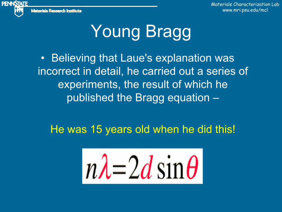
Young Bragg• Believing that Laue's explanation was incorrect in detail, he carried out a series of
experiments, the result of which he published the Bragg equation –
He was 15 years old when he did this!

Materials Characterization Labwww.mri.psu.edu/mcl
Bragg’s Law - defined
Wavelength1.54 A for Cu(known value)
X-ray incidence angle(known value)
Assume n=1 for the first order reflection (hkl=111)
Lattice inter-planar spacing of the crystal
Tells us at what angles X rays will be diffracted by a crystal when the X-ray wavelength and distance between
the crystal atoms are known

Materials Characterization Labwww.mri.psu.edu/mcl
Bragg’s Law
Assumptions:Monochromatic beamParallel beam
http://hyperphysics.phy-astr.gsu.edu/hbase/quantum/bragg.html

Materials Characterization Labwww.mri.psu.edu/mcl
Eventually……… Bragg-Brentano Diffractometer andThe Diffraction Pattern
10 20 30Two-Theta (deg)
0
500
1000
1500
2000
2500
3000
Intensity(C
ounts)
[solid-2R-2.raw]

Materials Characterization Labwww.mri.psu.edu/mcl
Development of Modern Spectrometers

Materials Characterization Labwww.mri.psu.edu/mcl
Invention of the X-ray Tube
• William D. Coolidge's name is inseparably linked with the X-ray tube-popularly called the 'Coolidge tube.'
Invention Impact
This invention completely revolutionized the generation of X-rays and remains to this day the model upon which all X-ray tubes are patterned.
• William D. Coolidge Born Oct 23 1873 - Died Feb 4 1975
Vacuum Tube (X-Ray) -Patented 1913
http://inventors.about.com/gi/dynamic/offsite.htm?site=http://www.invent.org/hall%5Fof%5Ffame/1%5F1%5F6%5Fdetail.asp%3FvInventorID=33

Materials Characterization Labwww.mri.psu.edu/mcl
The Coolidge Tube
• Ductile Tungsten- General Electric
• Metal powder was pressed, sintered and forged to thin rods.
•High Melting point – 3410 C •Low evaporation at high temp.•Tensile strength greater than steel
•Early filaments still sublimed too quickly; later added N2 and Ar to decrease tungsten evaporation
•But, these gases carried heat away from the filament – reducing brightness – winding into a fine coil reduced this heat loss.
http://inventors.about.com/gi/dynamic/offsite.htm?site=http://invsee.asu.edu/Modules/lightbulb/meathist4.htm

Materials Characterization Labwww.mri.psu.edu/mcl
Modern X-Ray Tube
Cross Section• In an X-ray tube, the high voltage
maintained across the electrodes draws electrons toward a metal target (the anode). X-rays are produced at the point of impact, and radiate in all directions.
http://pubs.usgs.gov/of/of01-041/htmldocs/xrpd.htm

Materials Characterization Labwww.mri.psu.edu/mcl
X-ray TubesATPS - Copper, normal focus, glass, x-ray tube used in Scintag diffractometers
Ceramic x-ray tubes used in Philips diffractometers

Materials Characterization Labwww.mri.psu.edu/mcl
Schematic of Bragg-Brentano Diffractometer
From the Siemens (now Bruker AXS) manual for the D5000

Materials Characterization Labwww.mri.psu.edu/mcl
Strengths / Limitations

Materials Characterization Labwww.mri.psu.edu/mcl
Strengths of X-ray Diffraction• Non-destructive – small amount of sample• Relatively rapid• Identification of compounds / phases – not just elements• Quantification of concentration of phases – (sometimes)• Classically for powders, but solids possible too• Gives information regarding crystallinity, size/strain, crystallite size, and
orientation
Limitations of X-ray Diffraction• Bulk technique – generally – unless a camera is uses• Not a “stand-alone” technique – often need chemical data• Complicated spectra – multiphase materials – identification /
quantification can be difficult
Materials Characterization Labwww.mri.psu.edu/mcl
MCL Instruments / Capabilities
Materials Characterization Labwww.mri.psu.edu/mcl
Powder Diffraction

Materials Characterization Labwww.mri.psu.edu/mcl
Scintag……Scintag 1
Scintag 2………
Both used for basic powderDiffraction.
Both horizontal θ/2θ geometry-tube is stationary- detector and sample move
Both located in 158 MRL building

Materials Characterization Labwww.mri.psu.edu/mcl
Scintag (cont’d)……..Scintag 3
Vertical θ/θ geometry- sample is stationary- tube and detector move
Hot (up to 1500C), Cold, and sample rotation stagesavailable
Grazing angle geometry possibleLocated in 158 MRL

Materials Characterization Labwww.mri.psu.edu/mcl
Philips X’Pert MPD
Located in room 164 MRI building
Standard θ/2θ Bragg-Brentano diffractometer
Grazing angle geometry possible.

Materials Characterization Labwww.mri.psu.edu/mcl
Single Crystal Diffractometers

Materials Characterization Labwww.mri.psu.edu/mcl
LaueMultiwire Laboratories
Consists of a position sensitive x-ray proportional counter connected to a computer system -orients and characterizes single crystals quickly in real-time.
Laue patterns can be easily stored, displayed, and printed - completely avoiding the use of film.
Located in 156 MRL

Materials Characterization Labwww.mri.psu.edu/mcl
Bruker 4-Circle
Located in 156 MRL
Structure determination ofSingle crystals – maximumDimension 0.3 mm.

Materials Characterization Labwww.mri.psu.edu/mcl
Philips 4-Circle
Located in room 164 MRI building
Low Resolution Optics –For Stress / Texture measurements inpoly-crystalline aggregates.
High Resolution Optics –uses an asymmetrical Bartelsmonochromator for collecting rocking curve data, crystal quality, and reciprocal space mapping.

Materials Characterization Labwww.mri.psu.edu/mcl
Applications at PSU

Materials Characterization Labwww.mri.psu.edu/mcl
Oxidation States of Copper
• The major phase is quartz, SiO2, (red) also a significant amount of Cu, (green). Perhaps, some Cu2O, (blue) but Cu2O directly overlaps the SiO2 lines. There is no CuO detected.
• Other unidentified phases also present. 34 35 36 37 38 39 40 41 42 43 44
Two-Theta (deg)
0
50
100
150
200
250
300
350
400
Inte
nsity
(Cou
nts)
[522-03.raw] , SCAN: 5.0/70.0/0.02/2(sec ), Cu(35kV,30mA), I(max)=2806, 07/03/03 08:20
46-1045> Quartz, syn - SiO244-0706> CuO - Copper Oxide
85-1326> Copper - Cu78-2076> Cuprite - Cu2O
CuOCuO
CuO
Cu2OSiO2
SiO2
SiO2
Cu2O
SiO2
Cu
As a fungicide on roofing materials

Materials Characterization Labwww.mri.psu.edu/mcl
Pyrite• Example of the mineral
pyrite, FeS2, that was found at a local road construction site.
25 30 35 40 45 50Two-Theta (deg)
0
50
100
150
200
250
300
350
Inte
nsity
(Cou
nts)
[pyrite sample.raw] , SCAN: 20.0/60.0/0.02/2(sec), Cu, I(max)=2179, 02/26/04 15:20
42-1340> Pyrite - FeS246-1045> Quartz, syn - SiO2
(Eq. 1) FeS2 + 7/2O2 + H2O = Fe2+ + 2SO4
2- + 2H+
(Eq. 2) Fe2+ + 1/4O2 + 3/2H2O = FeOOHppt + 2H+
(Eq. 3) FeS2 + 15/4O2 + 7/2H2O = Fe(OH)3ppt + 2SO4
2- + 4H+

Materials Characterization Labwww.mri.psu.edu/mcl
Rietveld Refinement• Quantify monoclinic and tetragonal zirconia – only the
100% tetragonal peak visible / clear from overlap
15 20 25 30 35 400
500
1000
45 50 55 60 65Two-Theta (deg)
0
500
1000
[powder ZrO2.raw] , SCAN: 5.0/70.0/0.02/2(sec), Cu(35kV,30mA), I(max)=2435, 03/04/04 14:58
37-1484> Baddeleyite, syn - ZrO250-1089> ZrO2 - Zirconium Oxide
Inte
nsity
(Cou
nts)
29 .5 29.6 29.7 29.8 29.9 30.0 30.1 30.2 30.3 30.4 30 .5 30.6 30.7 30 .8
mixture of tetragonal and monoclinic ZrO2.Goal: To quantif y the amount of tetragonal ZrO2 in a
red=monoclinicblue=tetragonal

Materials Characterization Labwww.mri.psu.edu/mcl
Crystallite Size Measurement
10 20 30 40 50 60 70Two-Theta (deg)
0
50
100
150
200
250
300
Inte
nsity
(Cou
nts)
[1%Rh5%Ni-CeO2-600C calcined (4degpermin).raw] , SCAN: 5.0/70.0/0.02/4(sec), Cu(35kV,30mA), I(max)=288, 05/13/04 09:50
43-1002> Cerianite-(Ce), syn - CeO247-1049> Bunsenite, syn - NiO
10 20 30 40 50 60 70Two-Theta (deg)
0
100
200
300
400
500
Inte
nsity
(Cou
nts)
[1%Rh5%Ni-CeO2-Aldrich(4degpermin).raw] , SCAN: 5.0/70.0/0.02/4(sec), Cu(35kV,30mA), I(max )=480, 05/13/04 08:39
43-1002> Cerianite-(Ce), syn - CeO2
10 20 30 40 50 60 70Two-Theta (deg)
0
50
100
150
200
Inte
nsity
(Cou
nts)
[1%Rh5%Ni-CeO2-Rhodia(4degpermin).raw] , SCAN: 5.0/70.0/0.02/4(sec), Cu(35kV,30mA), I(max)=208, 05/13/04 07:55
43-1002> Cerianite-(Ce), syn - CeO2
Rh-Ni CeO2 powdersτ = K λ
_______β cos θ
τ = particle sizeK = shape factor
(typically 0.85-0.9)λ = wavelength (Angstroms)β = corrected FWHM (radians)θ = ½ 2θ (peak position)
Decreasing crystallite size
Good for particle sizes < 500A and no strain.If strain, other Methods:Warren / AverbachWilliamson-Hall plot

Materials Characterization Labwww.mri.psu.edu/mcl
Grazing Angle Geometry
32.2 ATN (110)
46.0 ATN (200)
57.4 ATN (211)
Pt (111)
X
W Lα Pt (111)
Cu Kβ Pt (111)
Si (200)
32.2 ATN (110)
46.0 ATN (200)
57.4 ATN (211)
Normal Powder mode Grazing angle modeReflected X-rays
Incident x-rays
Silicon
Pt
ATN film
Materials Characterization Labwww.mri.psu.edu/mcl

Materials Characterization Labwww.mri.psu.edu/mcl
How to Get Started

Materials Characterization Labwww.mri.psu.edu/mcl
Dosimetry
• Wrist dosimeters are issued once each quarter.
• Worn on the wrist closest to the x-ray source (varies by instrument)

Materials Characterization Labwww.mri.psu.edu/mcl
Inside a Dosimeter
Measures radiation exposure due to x, gamma and beta radiation with optically stimulated luminescence (OSL) technology.
Thin strip of specially formulated aluminum oxide (Al2O3) crystalline material. During analysis, the Al2O3 strip is stimulated with selected frequencies of laser light causing it to luminesce in proportion to the amount of radiation exposure.
The luminescence measured during analysis is applied to a dose algorithm that relies on the response ratios between different filter positions within the dosimeter to discriminate between beta and photon (x and gamma) radiation fields to determine exposure results.

Materials Characterization Labwww.mri.psu.edu/mcl
Sample Preparation

Materials Characterization Labwww.mri.psu.edu/mcl
The “Perfect” Powder Sample• A “representative” sample – is it possible?
http://volcano.und.nodak.edu/vwdocs/minerals/bauxite.html
Bauxite

Materials Characterization Labwww.mri.psu.edu/mcl
The “Perfect” Powder Sample
• A “representative” sample
• Total randomness of the crystallite orientations• Sufficient number of crystallites • Sufficient intensity – limit of detection ~5%
Particle Size
< 325 mesh or < 400 mesh (38-44 micron) – qualitative
10 micron or less for quantitative – very difficult !

Materials Characterization Labwww.mri.psu.edu/mcl
“Real World” Samples
Some things can’t practically be powders:
filmspelletscrystalsmineral specimens
There are techniques available to deal with many of these – ask!

Materials Characterization Labwww.mri.psu.edu/mcl
Zero Background Holders (ZBH)
Flat Silicon ZBHCut parallel to Si (510)
Si (511) – also available, but has peak at 96ºθ
Quartz ZBH with cavityCut 6 º from (0001)
See www.gemdugout.com for additional information

Materials Characterization Labwww.mri.psu.edu/mcl
Flat Quartz ZBH
Vaseline Mount Smear Mount

Materials Characterization Labwww.mri.psu.edu/mcl
Side Drift Mount
Assembled
Disassembled
Designed to reduce preferred orientation – clay samples
Materials Characterization Labwww.mri.psu.edu/mcl
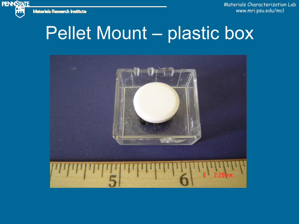
Pellet Mount – plastic box

Materials Characterization Labwww.mri.psu.edu/mcl
Shimmed Pellet Mount