xilinx xapp887 prc/eprc: data integrity and security ...€¦ · prc/eprc: data integrity and...
TRANSCRIPT
XAPP887 (v1.1) June 7, 2012 www.xilinx.com 1
© Copyright 2011–2012 Xilinx, Inc. XILINX, the Xilinx logo, Virtex, Spartan, ISE, and other designated brands included herein are trademarks of Xilinx in the United States and other countries. All other trademarks are the property of their respective owners.
Summary This application note describes a data integrity controller for partial reconfiguration (PRC) that can be included in any partially reconfigurable FPGA design to process partial bitstreams for data integrity. The controller achieves this by implementing cyclic redundancy check (CRC) in FPGA logic for partial bitstreams before loading them through the internal configuration access port (ICAP). A special version of the controller for encrypted partial reconfiguration (EPRC) also enables encrypted partial bitstreams to use the internal configuration logic for decryption.
This application note is only applicable to Virtex®-5 and Virtex-6 devices. It is assumed that the reader is familiar with partial reconfiguration concepts and tools flow.
Note: The Perl script required for the software step of this application note uses two Perl modules that provide encryption functionality. These modules, provided with the application note materials, are copyrighted by various third parties and licensed by such third parties under the Artistic License.
Introduction Partial reconfiguration of Virtex FPGAs requires the use of partial bitstreams. These bitstreams reprogram region(s) of an operational FPGA with new functionality without disrupting the functionality or compromising the integrity of the remainder of the device. However, loading a faulty or corrupted partial bitstream might cause incorrect design behavior not only in the region undergoing reprogramming but also in the entire device. Although no device damage has ever been reported for loading a faulty partial bitstream, it is not a certainty that damage could never occur, nor that the system that the FPGA device is controlling would not be damaged.
Reprogramming the device with a correct partial or full bitstream can be the simplest recovery method. However, for some systems, it is essential to validate the integrity of partial bitstreams before loading them into the device. This is because halting the design operation to reprogram the entire device is undesirable or delivering partial bitstreams is error prone (e.g., radio transmission).
All these precautions are critical features of a robust and reliable design. Additionally, secure applications might use encrypted partial bitstreams that require special handling. The PRC/EPRC core provides mechanisms, in both software and hardware, to achieve data integrity and encryption support for partial bitstreams.
General Description
Error Checking
In Virtex architectures, the configuration logic continuously calculates a CRC value as it loads a full bitstream into the configuration memory. After completely loading the configuration data, configuration logic can match the calculated CRC value with the expected value contained at the end of the full bitstream. If not matched, the device aborts configuration and never enters the user mode for normal operation. After initial configuration, because partial bitstreams are loaded into an operational device, it is desirable to perform error checking prior to altering any part of the configuration memory.
The configuration logic cannot facilitate this type of CRC checking for partial bitstreams mainly because it lacks a buffering mechanism as it reads the partial bitstreams. Thus, the PRC system implements CRC checking of partial bitstreams in FPGA logic before loading them through the ICAP. To make buffering of partial bitstreams feasible, software packetizes the
Application Note: Virtex-5 and Virtex-6 FPGAs
XAPP887 (v1.1) June 7, 2012
PRC/EPRC: Data Integrity and Security Controller for Partial ReconfigurationAuthor: Amir Zeineddini and Jim Wesselkamper

General Description
XAPP887 (v1.1) June 7, 2012 www.xilinx.com 2
partial bitstreams into 2 KB segments. The two steps involved in the process are described below.
Software Step
Using the provided Perl script, the user splits a partial bitstream (originally generated by BitGen) into packets. Each packet contains a sequence number, length, configuration data, and CRC value.
A single packet can be up to 2,048 bytes or 512 32-bit words. The first 32-bit word of the packet is a packet header that contains a packet length in the least significant nine bits of the low-order 16 bits and a sequence number in the least significant eight bits of the high-order 16 bits. The last word of the packet contains a CRC32 value calculated across the entire packet, including the packet header. The length includes all the words in the packet, including the packet header and the final word containing the CRC value.
The Perl script also scrambles the IDCODE in the partial bitstream. This precaution is used so that script-modified partial bitstreams are not mistakenly used as normal partial bitstreams. The PRC/EPRC core in hardware descrambles the IDCODE into its original value. The BitGen-generated .bit files contain proprietary header information that does not need to be downloaded to the FPGA. The last word of this header information contains the total byte size of the configuration data that follows the header. The script-generated .prc files preserve the header information and update the total byte size with the added number of bytes for all packet headers and CRC words. This updated value can inform the user of the total byte size of the configuration data that needs to be sent to the PRC/EPRC core.
The following code illustrates the structure of a sample partial bitstream after running the script:
- Bitstream Header (if included)- 00 00 01 FF (Packet 0, length: 512)- Configuration Data (510 words)- 95 BD EA 34 (Packet 0 CRC)- 00 01 01 FF (Packet 1, length: 512)- Configuration Data (510 words)- 26 A1 C6 19 (Packet 1 CRC)
.
.
.- 00 1D 00 11 (Packet 29, length: 4)- Configuration Data (Two words)- 8E D7 C8 47 (Last Packet CRC)
Script Usage
The eprBitgen.pl script splits the partial bitstream into packets and adds CRC values to each packet. For all Virtex-6 FPGA designs and non-encrypted Virtex-5 FPGA designs, the script can be run from the command prompt by typing:
xilperl eprBitgen.pl -pb <partialbitfile1[.bit]> -pb <partialbitfileN[.bit]>
Where -pb <partialbitfile[.bit]> is the input partial bitstream file. Multiple partial bitstreams can be specified. The generated file(s) have a .prc extension.
Hardware Step
The PRC core, provided as a netlist (PRC.ngc) and implemented with the user design, validates the content of each packet in hardware by calculating a new CRC value and matching it to the one contained in the packet. The core also checks the ordering of the received packets by monitoring the contained sequence number in each packet. After successful verification, the PRC core forwards only the configuration data of each packet to the ICAP for partial reconfiguration.

General Description
XAPP887 (v1.1) June 7, 2012 www.xilinx.com 3
Encryption Support
Virtex-5 and Virtex-6 devices have on-chip advanced encryption standard (AES) decryption logic that provides design security against potential attacks aimed at copying or reverse-engineering the design. To generate encrypted full bitstreams, the user specifies a 256-bit key and sets the encryption options for BitGen. (For specific BitGen commands and syntax, refer to Command Line Tools User Guide [Ref 1].)
After loading the encryption key into the device, the configuration logic decrypts the encrypted full bitstream while loading it into the configuration memory. For encrypted partial bitstreams, the same process applies, with the exception that BitGen is only capable of generating encrypted partial bitstreams for Virtex-6 devices, not Virtex-5 devices.
The following sections explain how the EPRC system incorporates encryption support in addition to its error-checking scheme for each device.
Virtex-5 Devices
Because BitGen does not generate encrypted partial bitstreams for Virtex-5 devices, the EPRC system also encrypts the content of partial bitstreams in the software step before packetizing and inserting CRC values. The two steps involved in the process are described here.
Software Step
Using the provided Perl script, the user encrypts the partial bitstream and then splits the encrypted partial bitstream into packets. Each encrypted packet contains a sequence number, length, configuration data, and CRC value. Packet details are similar to PRC.
Script Usage
The eprBitgen.pl script splits the partial bitstream into packets, decrypts, and adds CRC values to each packet. For all encrypted Virtex-5 FPGA designs, the script can be run from the command prompt by typing:
xilperl eprBitgen.pl -fb <fullbitfile[.bit]> -pb <partialbitfile1[.bit]> -pb <partialbitfileN[.bit]> -key <keyfile[.nky]> --encrypt
Where
-fb <fullbitfile[.bit]> is the input full bitstream file
-pb <partialbitfile[.bit]> is the input partial bitstream file
-key <keyfile[.bit]> is the input key file
--encrypt enables encryption
Note: The eprBitgen.pl script uses two Perl modules (Crypt::CBC and Crypt::Rijndael) that provide encryption functionality. These modules are copyrighted by various third parties and licensed by such third parties under the Artistic License.
Multiple partial bitstreams can be specified. A full bitstream is needed to borrow static frames to round out the partial reconfiguration data into full AES-256 blocks.
The internal configuration memory of a Virtex device is subdivided into segments called frames. Bitstreams contain the address and content of these frames in the form of write commands to specific registers used by internal configuration logic: the Frame Data Register In (FDRI) and the Frame Address Register (FAR). The FDRI is a pipeline input stage for configuration data frames to be stored in the configuration memory. The FAR specifies the frame address. A non-encrypted partial bitstream generated by BitGen contains write blocks to the FDRI register. Each FDRI block consists of an address write to the FAR register and a multi-word write to the FDRI register.
For Virtex-5 devices, BitGen protects the full bitstreams by encrypting the FDRI writes with AES-256. However, this method of encrypting FDRI requires FDRI data to be evenly divisible by the AES-256 block size and the data content of FAR writes to be zero.
General Description
XAPP887 (v1.1) June 7, 2012 www.xilinx.com 4
The script makes all FDRI writes evenly divisible by an AES-256 block by adding additional configuration data from static regions. The script also changes the ordering in which frames are written so that I/O frames are written last. Another restriction when working with encrypted Virtex-5 device bitstreams is that the FAR cannot be written with non-zero values. Thus, the script substitutes the data content of FAR writes with frame word offsets so that the EPRC can perform read-ahead commands to reach the appropriate configuration frames within the device.
Note: Virtex-5 device encrypted partial bitstreams cannot initialize block RAMs. This is because the read-ahead commands needed for replacing the FAR writes make static block RAMs inaccessible to the user design during reconfiguration.
Hardware Step
The Virtex-5 device EPRC core, provided as a netlist (EPRC_V5.ngc) and implemented with the user design, validates the content of each packet in hardware similar to the PRC core.
After the verification is successfully completed, the configuration module of the Virtex-5 device EPRC core sends additional configuration commands (details described in CONFIG, page 6) to handle the encrypted partial bitstream. This happens before forwarding the encrypted configuration data of each packet to the ICAP for partial reconfiguration. Internal decryption logic then decrypts the encrypted configuration data while loading it into the configuration memory.
Note: The netlist provided contains an 8-bit ICAP interface and requires x8 ICAP instantiation.
Virtex-6 Devices
BitGen generates both encrypted and non-encrypted partial bitstreams for Virtex-6 devices. The process is similar to the full bitstreams explained at the beginning of Encryption Support, page 3. (For specific BitGen commands and syntax, refer to Command Line Tools User Guide [Ref 1].) BitGen encrypts the entire Virtex-6 FPGA partial bitstream and pads the end of the bitstream with NOP commands so that the entire bitstream is evenly divided into AES-256 encryption blocks. The partial bitstream requires no further processing besides CRC checking by the EPRC system before forwarding the encrypted configuration data of each packet to the ICAP for partial reconfiguration. The two steps involved in the process are:
Software step
For Virtex-6 devices, the EPRC system processes BitGen-generated encrypted partial bitstreams in the same way as non-encrypted bitstreams to packetize the content and insert CRC values. Script usage is the same as for the PRC as described in Script Usage, page 2.
Hardware step
The Virtex-6 FPGA EPRC core, provided as a netlist (EPRC_V6.ngc) and implemented with the user design, validates the content of each packet in hardware similar to the PRC core.
After successful verification, the PRC core only forwards the configuration data of each packet to the ICAP for partial reconfiguration. Internal decryption logic then decrypts the encrypted configuration data while loading it into the configuration memory.
Note: The netlist provided contains an 8-bit ICAP interface and requires x8 ICAP instantiation.

Functional Description
XAPP887 (v1.1) June 7, 2012 www.xilinx.com 5
Functional Description
Figure 1 shows a top-level view of the different blocks in the PRC/EPRC core.
Note: ICAP_CLK and FIFO_CLK are independent clocks (asynchronous) with different domains. The maximum frequency recommended for ICAP_CLK is 100 MHz, as specified for ICAP primitives. The maximum frequency recommended for FIFO_CLK is 250 MHz. However, higher frequencies might be possible if the design meets timing.
PACKET FIFO
This module ensures that incoming packets pass error checking prior to being forwarded onto other modules in the core. The PACKET FIFO module receives the packets through a FIFO interface and uses the packet information (length, sequence number, and CRC value) to perform error checking.
After PR_LOAD assertion, the first received packet must contain a sequence number equal to 0x0. Each subsequent packet contains a sequence number one greater than the prior packet. At 0xFF, the sequence number should roll back over to 0x0. If the CRC32 value or the sequence number does not match the expected value, the PACKET_ERROR signal is asserted and the packet is not forwarded.
The data is stored in a FIFO until the last word of the packet is received. The last word is identified based on the length received in the first word. After the last word is received, the count for the number of packets stored in the FIFO is incremented if the sequence number and CRC check pass. The FIFO is determined to be full if the number of stored words equals 1,023. The FIFO size is 4 KB which can contain up to two maximum-size (512 words) packets.
The packet information (length, sequence number, and CRC value) provides error checking up to the packet FIFO. Parity calculation is used to maintain data integrity throughout the rest of the core. The read data from the FIFO is forwarded to the next module with back pressure control.
The PACKET FIFO module asserts the error signal, PACKET_ERROR, when the error checking fails, data is written into a full packet FIFO (overflow), or data is read from an empty packet FIFO (underflow). The error signal persists until PR_LOAD is removed, resulting in an PRC/EPRC-wide reset. Any remaining packets received after an error is reported will not be
X-Ref Target - Figure 1
Figure 1: PRC/EPRC Architecture
PACKETFIFO
CONFIGICAP
OUTPUTS
RESET ERROR
FIFO 16 x 11
ICAP_CLK Clock DomainFIFO_CLK Clock Domain
PR_ERROR
X887_01_120810
PACKET ERROR
CONFIGERROR
CONFIGDATA/WE
PR_LOAD
FIFO_LOW
FIFO STATUS
FIFO_CLKFIFODATA/
STATUS
FIFO RD
ICAP_BUSY
ICAP_CLKPACKET
DATA/STATUS
PACKET RDFIFO_DIN
FIFO_WE
FIFO_FULL
PR_ERROR_CODE
PR_DONE
ICAP_DO
ICAP_DI
ICAP_DIP
ICAP_WEB
ICAP_CEB

Functional Description
XAPP887 (v1.1) June 7, 2012 www.xilinx.com 6
forwarded to other modules. Thus, it is not required to complete sending all remaining packets after an error.
CONFIG
The CONFIG module monitors configuration data forwarded from the PACKET FIFO module for configuration commands. It also descrambles the IDCODE into its original value.
Note: For encrypted partial bitstreams in Virtex-5 devices only, the CONFIG module substitutes all FAR writes with read operations equivalent in size to the number of words specified in the FAR data for that write. The module applies back pressure on the incoming data stream rather than reading data from the PACKET FIFO. When a non-zero FAR write occurs, the next configuration command is left in the PACKET FIFO while the configuration logic performs the read ahead.
The EPRC configuration logic then divides the data into bytes and sends the data to the ICAP interface through the ICAP FIFO. The full signal from the FIFO applies back pressure towards CONFIG. The empty signal is used by the ICAP OUTPUTS module to know when to read data from the FIFO. The CONFIG module asserts the error signal, CONFIG_ERROR, when the original partial bitstream contains invalid commands or information. The error is determined internally and the faulty data is never passed to the ICAP. The ICAP output (ICAP_DO) is not used for determining error conditions. The CONFIG module always asserts PR_DONE, even in case of an error. It is expected to always wait for PR_DONE assertion before deasserting PR_LOAD even if PR_ERROR is asserted first. This allows for any clean-up that needs to be done by the core (e.g. sending an ABORT to ICAP). PR_DONE assertion always requires EXT_PR_DONE input to be high (Logic 1).
ICAP OUTPUTS
The ICAP OUTPUTS module is responsible for reading the ICAP FIFO and output. It also monitors the PR_ERROR signals for status. The ICAP OUTPUTS module generates an abort sequence and stops reading the ICAP FIFO if it detects an error condition.
RESET
The RESET module consists of a 3-bit down counter. The most significant bit (MSB) of the counter decrements the counter and is tied to the active-High RESET output. The counter is asynchronously loaded with 111 when PR_LOAD is deasserted (logic 0). After PR_LOAD is asserted, the down counter counts down until the MSB is zero. At this point, the counter stops decrementing and the RESET output is deasserted. The final count value is 011.
ERROR
The ERROR module encodes the various error signals inside the core into PR_ERROR and PR_ERROR_CODE signals for external usage. Table 1 shows the encoding of the PR_ERROR_CODE signal.
Table 1: PR_ERROR_CODE Encoding
Inputs Outputs
EXT_PR_ERROR RESERVED CONFIG_ERROR PACKET_ERROR PR_ERROR_CODE
1 X X X 1 and EXT_PR_ERROR_CODE
0 0 1 X 0010
0 0 0 1 0001
0 0 0 0 0000
Top-Level Interface Signals
XAPP887 (v1.1) June 7, 2012 www.xilinx.com 7
Resending Procedure after Errors
The error signal persists until PR_LOAD is deasserted which results in a PRC/EPRC-wide reset that allows for a new partial bitstream to be sent to the PRC/EPRC core. After the occurrence of any type of an error (PACKET/CONFIG), PR_ERROR is always followed by PR_DONE. Thus, it is required to wait for PR_DONE assertion before deasserting PR_LOAD. This allows the core to complete any action that needs to be done after the error.
A PR_ERROR from the PRC/EPRC core should result in a system-level decision of either retrying with the same partial bitstream or first cleaning up with a blank partial bitstream. In case of a packet error, it is not possible to resend the packets from where the error was encountered. Reconfiguration of any reconfigurable partition is allowed after an error.
Top-Level Interface Signals
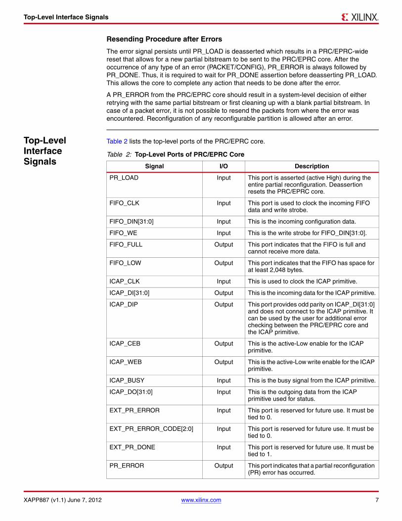
Table 2 lists the top-level ports of the PRC/EPRC core.
Table 2: Top-Level Ports of PRC/EPRC Core
Signal I/O Description
PR_LOAD Input This port is asserted (active High) during the entire partial reconfiguration. Deassertion resets the PRC/EPRC core.
FIFO_CLK Input This port is used to clock the incoming FIFO data and write strobe.
FIFO_DIN[31:0] Input This is the incoming configuration data.
FIFO_WE Input This is the write strobe for FIFO_DIN[31:0].
FIFO_FULL Output This port indicates that the FIFO is full and cannot receive more data.
FIFO_LOW Output This port indicates that the FIFO has space for at least 2,048 bytes.
ICAP_CLK Input This is used to clock the ICAP primitive.
ICAP_DI[31:0] Output This is the incoming data for the ICAP primitive.
ICAP_DIP Output This port provides odd parity on ICAP_DI[31:0] and does not connect to the ICAP primitive. It can be used by the user for additional error checking between the PRC/EPRC core and the ICAP primitive.
ICAP_CEB Output This is the active-Low enable for the ICAP primitive.
ICAP_WEB Output This is the active-Low write enable for the ICAP primitive.
ICAP_BUSY Input This is the busy signal from the ICAP primitive.
ICAP_DO[31:0] Input This is the outgoing data from the ICAP primitive used for status.
EXT_PR_ERROR Input This port is reserved for future use. It must be tied to 0.
EXT_PR_ERROR_CODE[2:0] Input This port is reserved for future use. It must be tied to 0.
EXT_PR_DONE Input This port is reserved for future use. It must be tied to 1.
PR_ERROR Output This port indicates that a partial reconfiguration (PR) error has occurred.

Timing Diagrams
XAPP887 (v1.1) June 7, 2012 www.xilinx.com 8
The PR_DONE output port is dependent on multiple internal flags for a greater number of clock cycles to ensure that all configuration information has been given adequate time to be delivered to the ICAP. In the design archive on www.xilinx.com, the PRC and EPRC .ngc cores have been updated with this more exhaustive check. The example designs and sample bitstreams have also been recompiled with these new cores. The Perl scripts require no modification to accommodate the new cores.
Timing Diagrams
PRC/EPRC provides a simple FIFO interface to the user. Timing diagrams that show major core interface transactions are shown in Figure 2 to Figure 6.
Figure 2 shows the FIFO write for the first word of the first packet. The user asserts PR_LOAD and waits for FIFO_FULL to go Low. Then, the user asserts FIFO_WE while the data word is present on FIFO_DIN at the same cycle. Any subsequent FIFO write should happen while FIFO_FULL is Low to avoid overflow.
PR_ERROR_CODE[3:0] Output This is the error code for the PR error.
PR_DONE Output This port indicates that the PR operation has completed.
Table 2: Top-Level Ports of PRC/EPRC Core (Cont’d)
Signal I/O Description
X-Ref Target - Figure 2
Figure 2: FIFO Write
PRC_PR_LOAD
PRC_FIFO_FULL
PRC_FIFO_LOW
PRC_FIFO_DIN
PRC_FIFO_WE
PRC_PR_ERROR
PRC_PR_ERROR_CODE
PRC_PR_DONE
ICAP_DO
ICAP_DI
ICAP_BUSY
ICAP_CEB
ICAP_WEB
000001FF
X887_02_111910

Timing Diagrams
XAPP887 (v1.1) June 7, 2012 www.xilinx.com 9
Figure 3 shows a FIFO write that causes the core to deassert FIFO_LOW (logic 0). This indicates that the FIFO has space for less than 2,048 bytes.
Figure 4 shows a FIFO write that causes the core to assert FIFO_FULL (logic 1). This indicates that the FIFO cannot receive any more data.
X-Ref Target - Figure 3
Figure 3: FIFO_LOW Deassertion After Write
X-Ref Target - Figure 4
Figure 4: FIFO_FULL Assertion After Write
PRC_PR_LOAD
PRC_FIFO_FULL
PRC_FIFO_LOW
PRC_FIFO_DIN
PRC_FIFO_WE
PRC_PR_ERROR
PRC_PR_ERROR_CODE
PRC_PR_DONE
ICAP_DO
ICAP_DI
ICAP_BUSY
ICAP_CEB
ICAP_WEBX887_03_111910
PRC_PR_LOAD
PRC_FIFO_FULL
PRC_FIFO_LOW
PRC_FIFO_DIN
PRC_FIFO_WE
PRC_PR_ERROR
PRC_PR_ERROR_CODE
PRC_PR_DONE
ICAP_DO
ICAP_DI
ICAP_BUSY
ICAP_CEB
ICAP_WEBX887_04_111910
Timing Diagrams
XAPP887 (v1.1) June 7, 2012 www.xilinx.com 10
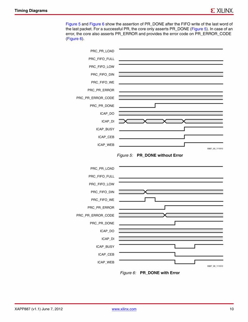
Figure 5 and Figure 6 show the assertion of PR_DONE after the FIFO write of the last word of the last packet. For a successful PR, the core only asserts PR_DONE (Figure 5). In case of an error, the core also asserts PR_ERROR and provides the error code on PR_ERROR_CODE (Figure 6).
X-Ref Target - Figure 5
Figure 5: PR_DONE without Error
X-Ref Target - Figure 6
Figure 6: PR_DONE with Error
PRC_PR_LOAD
PRC_FIFO_FULL
PRC_FIFO_LOW
PRC_FIFO_DIN
PRC_FIFO_WE
PRC_PR_ERROR
PRC_PR_ERROR_CODE
PRC_PR_DONE
ICAP_DO
ICAP_DI
ICAP_BUSY
ICAP_CEB
ICAP_WEBX887_05_111910
PRC_PR_LOAD
PRC_FIFO_FULL
PRC_FIFO_LOW
PRC_FIFO_DIN
PRC_FIFO_WE
PRC_PR_ERROR
PRC_PR_ERROR_CODE
PRC_PR_DONE
ICAP_DO
ICAP_DI
ICAP_BUSY
ICAP_CEB
ICAP_WEBX887_06_111910

PRC/EPRC Deliverables
XAPP887 (v1.1) June 7, 2012 www.xilinx.com 11
PRC/EPRC Deliverables
The PRC/EPRC deliverables consist of:
• Perl script required for .prc partial bitstream generation
• PRC netlist (PRC.ngc) for both Virtex-5 FPGA and Virtex-6 FPGA designs (CRC checking only)
• EPRC netlist (EPRC_V5.ngc) for Virtex-5 FPGA encrypted designs
• EPRC netlist (EPRC_V6.ngc) for Virtex-6 FPGA encrypted designs
• Example designs for ML505 and ML605 boards
Example Designs
The purpose of the reference designs created for this application note is to show the integration of the PRC/EPRC core into Virtex-5 FPGA or Virtex-6 FPGA PR designs. The example designs incorporate the netlist provided for each core and include additional features to facilitate working with PRC/EPRC core.
The Color2 sample design, used in Partial Reconfiguration User Guide [Ref 2], is augmented with the PRC/EPRC core targeting both ML505 and ML605 boards. The original Color2 design generates RGB color bars for the digital visual interface (DVI) of a display and allows partial reconfiguration of color bars through external configuration interfaces. In addition, slow or fast variants of each color match the speed of blinking LEDs on the target board.
In the reference designs, the Color2 design keeps its original functionality and incorporates the PRC/EPRC core with the addition of:
• ICAP primitive: This is required as the configuration interface instead of an external one. The instantiation must have the correct width parameter for each design: X32 width for PRC and X8 width for EPRC.
• System ACE™ interface: This is used as a delivery method for partial bitstreams. The task of this system is to send the partial bitstreams from a storage device (such as a CompactFlash card) to the PRC/EPRC core. To do so, the system correctly interacts with the PRC/EPRC interface (e.g., asserting load/write, monitoring FIFO/error status, etc.). In addition, System ACE interface provides a simple UART console to help the user select the partial bitstreams, check the design status after PR, and identify the error conditions, if any. This system is provided as an example for delivering the partial bitstream to the PRC/EPRC core. Users are allowed to select any desirable method for delivering the configuration data to the cores.
• ChipScope™ analyzer core: This is implemented in each design in order for the user to observe the PRC/EPRC interface signals as the design operates on the board.
Figure 7 shows the hierarchy of the example designs.
X-Ref Target - Figure 7
Figure 7: Color2 Design Hierarchy with PRC/EPRC Core
Top Level
ICAP Primitive(Static)
DVI_IF, IIC_INIT, VGA,CLK Modules
(Static)
RGB Modules(Reconfigureable)
X887_07_111910
SysACE System(Static)
PRC/EPRC(Static)

Example Designs
XAPP887 (v1.1) June 7, 2012 www.xilinx.com 12
Directory Structure
The directory structure of the example designs is set up as:
• PRC or EPRC
• ML505 or ML605
- planahead: This folder contains the PR implementation of the design.
- ready_bitfiles: This folder contains script files, script-generated .prc files, and input partial bitfiles copied and renamed from the planahead folder for PRC and full_encrypted folder for EPRC.
Note: For EPRC designs, ready_bitfiles also contains the full_encrypted folder that contains encrypted full and partial bitfiles generated by BitGen, as well as the required input files.
- synthesis: This folder contains the ISE® software projects for static and reconfigurable modules, along with the required HDL and netlist files.
Note: For each design, the top.v file in the static folder contains the instantiation of the PRC/EPRC core.
Demonstration
Figure 8 shows how to set up the hardware to run each design on its target board.
The steps involved in the demonstration process are:
1. For each PRC/EPRC design, copy all the script-generated .prc files to the root directory of the CompactFlash card of the target board. The copied files should keep the original naming.
2. Set up the physical connections:
a. Insert the CompactFlash card onto the target board.
b. Connect the JTAG cable to the host PC.
c. Connect the UART cable to the host PC. A serial port cable is used for the ML505 board, while a USB cable is used for the ML605 board. Ensure that the Silicon Labs USB-to-UART drivers are installed on the PC and the assigned COM port matches the settings of the UART console program used. (The Silicon Labs USB-to-UART drivers can be downloaded from http://www.silabs.com/products/mcu/Pages/USBtoUARTBridgeVCPDrivers.aspx.)
X-Ref Target - Figure 8
Figure 8: Example Designs Hardware Setup
UARTConsole
UART
JTAG
DVI
X887_08_111910
FlashCard

Appendix
XAPP887 (v1.1) June 7, 2012 www.xilinx.com 13
d. Connect the DVI cable to a display.
3. Set up the software:
a. Launch iMPACT.
b. Launch a terminal program at 115200, 8, N, 1.
4. Load the initial configuration:
a. For PRC designs, program the FPGA with the full bitstream.
b. For EPRC designs, program the FPGA with the key used for encrypting the full bitstream. Select the Enable Encrypted Reconfig option in iMPACT.
Note: For the ML605 board, press the PROG pulse before loading the key. The provided key is a sample key used for the example designs. A more secure key should be used for any actual encrypted design.
c. Program the FPGA with the full bitstream.
5. Carry out the partial reconfiguration:
a. Follow the instructions on the UART console to select and load the desired partial bitstream. After partial reconfiguration, the shade of the color bars on the display and the speed of blinking LEDs change accordingly. This message appears on the console:
<PR download success>
b. Use a hex editor to open any of the copied partial bitstreams on the flash card. Modify a value inside a packet. Save the file and copy it back to the CompactFlash card. Follow the instructions on the UART console to select and load the modified partial bitstream. After partial reconfiguration, this message appears on the console:
<PR download error> Packet Error!
6. Use the ChipScope analyzer:
a. Launch the ChipScope analyzer and use the .cdc file generated in the PlanAhead™ tool runs of each design.
b. Analyze the transactions of the PRC/EPRC core interface in the ChipScope analyzer.
Appendix HDL Instantiation Templates
The VHDL instantiation template is shown here:
component PRC port (
-- Module-wide load signal synchronous to fifo_clk PR_LOAD : in std_logic;
-- Incoming fifo signals FIFO_CLK : in std_logic; FIFO_DIN : in std_logic_vector(31 downto 0); FIFO_WE : in std_logic; FIFO_FULL : out std_logic; FIFO_LOW : out std_logic; -- Outgoing icap interface ICAP_CLK : in std_logic; ICAP_DI : out std_logic_vector(31 downto 0); ICAP_DIP : out std_logic; ICAP_CEB : out std_logic; ICAP_WEB : out std_logic; ICAP_BUSY : in std_logic; ICAP_DO : in std_logic_vector(31 downto 0);

Appendix
XAPP887 (v1.1) June 7, 2012 www.xilinx.com 14
-- Programming status EXT_PR_ERROR : in std_logic; EXT_PR_ERROR_CODE : in std_logic_vector(2 downto 0); EXT_PR_DONE : in std_logic; PR_ERROR : out std_logic; PR_ERROR_CODE : out std_logic_vector(3 downto 0); PR_DONE : out std_logic
);end component;
NOTE: for EPRC, only bits 7 to 0 of ICAP_DI and ICAP_DO actually connect to ICAP primitive.
The Verilog instantiation template is shown here.
module PRC ( PR_LOAD, FIFO_CLK, FIFO_DIN, FIFO_WE, FIFO_FULL, FIFO_LOW, ICAP_CLK, ICAP_DI, ICAP_DIP, ICAP_CEB, ICAP_WEB, ICAP_BUSY, ICAP_DO, EXT_PR_ERROR, EXT_PR_ERROR_CODE, EXT_PR_DONE, PR_ERROR, PR_ERROR_CODE, PR_DONE);
input PR_LOAD; input FIFO_CLK; input [31:0] FIFO_DIN; input FIFO_WE; input ICAP_CLK; input ICAP_BUSY; input [31:0] ICAP_DO; input EXT_PR_ERROR; input [2:0] EXT_PR_ERROR_CODE; input EXT_PR_DONE;
output FIFO_FULL; output FIFO_LOW; output [31:0] ICAP_DI; output ICAP_DIP; output ICAP_CEB; output ICAP_WEB; output PR_ERROR; output [3:0] PR_ERROR_CODE; output PR_DONE;endmodule
NOTE: for EPRC, only bits 7 to 0 of ICAP_DI and ICAP_DO actually connect to ICAP primitive.
Reference Design
XAPP887 (v1.1) June 7, 2012 www.xilinx.com 15
Reference Design
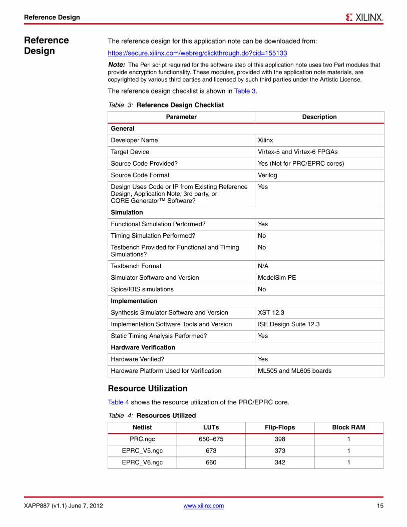
The reference design for this application note can be downloaded from:
https://secure.xilinx.com/webreg/clickthrough.do?cid=155133
Note: The Perl script required for the software step of this application note uses two Perl modules that provide encryption functionality. These modules, provided with the application note materials, are copyrighted by various third parties and licensed by such third parties under the Artistic License.
The reference design checklist is shown in Table 3.
Resource Utilization
Table 4 shows the resource utilization of the PRC/EPRC core.
Table 3: Reference Design Checklist
Parameter Description
General
Developer Name Xilinx
Target Device Virtex-5 and Virtex-6 FPGAs
Source Code Provided? Yes (Not for PRC/EPRC cores)
Source Code Format Verilog
Design Uses Code or IP from Existing Reference Design, Application Note, 3rd party, or CORE Generator™ Software?
Yes
Simulation
Functional Simulation Performed? Yes
Timing Simulation Performed? No
Testbench Provided for Functional and Timing Simulations?
No
Testbench Format N/A
Simulator Software and Version ModelSim PE
Spice/IBIS simulations No
Implementation
Synthesis Simulator Software and Version XST 12.3
Implementation Software Tools and Version ISE Design Suite 12.3
Static Timing Analysis Performed? Yes
Hardware Verification
Hardware Verified? Yes
Hardware Platform Used for Verification ML505 and ML605 boards
Table 4: Resources Utilized
Netlist LUTs Flip-Flops Block RAM
PRC.ngc 650–675 398 1
EPRC_V5.ngc 673 373 1
EPRC_V6.ngc 660 342 1

References
XAPP887 (v1.1) June 7, 2012 www.xilinx.com 16
References This application note uses the following references:
1. UG628, Command Line Tools User Guide.
2. UG702, Partial Reconfiguration User Guide.
3. DS152, Virtex-6 FPGA Data Sheet: DC and Switching Characteristics.
4. UG360, Virtex-6 FPGA Configuration User Guide.
5. DS202, Virtex-5 FPGA Data Sheet: DC and Switching Characteristics.
6. UG191, Virtex-5 FPGA Configuration User Guide.
Revision History
The following table shows the revision history for this document.
Notice of Disclaimer
Xilinx is disclosing this Application Note to you “AS-IS” with no warranty of any kind. This Application Noteis one possible implementation of this feature, application, or standard, and is subject to change withoutfurther notice from Xilinx. You are responsible for obtaining any rights you may require in connection withyour use or implementation of this Application Note. XILINX MAKES NO REPRESENTATIONS ORWARRANTIES, WHETHER EXPRESS OR IMPLIED, STATUTORY OR OTHERWISE, INCLUDING,WITHOUT LIMITATION, IMPLIED WARRANTIES OF MERCHANTABILITY, NONINFRINGEMENT, ORFITNESS FOR A PARTICULAR PURPOSE. IN NO EVENT WILL XILINX BE LIABLE FOR ANY LOSS OFDATA, LOST PROFITS, OR FOR ANY SPECIAL, INCIDENTAL, CONSEQUENTIAL, OR INDIRECTDAMAGES ARISING FROM YOUR USE OF THIS APPLICATION NOTE.
The Crypt::Rijndael module was obtained from http://cpansearch.perl.org/src/DELTA/Crypt-Rijndael_PP-0.04/Rijndael_PP.pm and the Crypt::CBC module was obtained fromhttp://cpansearch.perl.org/src/LDS/Crypt-CBC-2.24/CBC.pm. Xilinx believes that the version of theArtistic License below (which was obtained from http://dev.perl.org/licenses/artistic.html) is the relevantlicense for these items.
The “Artistic License”Preamble
The intent of this document is to state the conditions under which a Package may be copied, such that the Copyright Holder maintainssome semblance of artistic control over the development of the package, while giving the users of the package the right to use anddistribute the Package in a more-or-less customary fashion, plus the right to make reasonable modifications.
Definitions"Package" refers to the collection of files distributed by the Copyright Holder, and derivatives of that collection of files created throughtextual modification."Standard Version" refers to such a Package if it has not been modified, or has been modified in accordance with the wishes of theCopyright Holder as specified below."Copyright Holder" is whoever is named in the copyright or copyrights for the package."You" is you, if you're thinking about copying or distributing this Package."Reasonable copying fee" is whatever you can justify on the basis of media cost, duplication charges, time of people involved, and so on.(You will not be required to justify it to the Copyright Holder, but only to the computing community at large as a market that must bear thefee.)"Freely Available" means that no fee is charged for the item itself, though there may be fees involved in handling the item. It also meansthat recipients of the item may redistribute it under the same conditions they received it1. You may make and give away verbatim copies of the source form of the Standard Version of this Package without restriction, providedthat you duplicate all of the original copyright notices and associated disclaimers.2. You may apply bug fixes, portability fixes and other modifications derived from the Public Domain or from the Copyright Holder. APackage modified in such a way shall still be considered the Standard Version.3. You may otherwise modify your copy of this Package in any way, provided that you insert a prominent notice in each changed filestating how and when you changed that file, and provided that you do at least ONE of the following:
a) place your modifications in the Public Domain or otherwise make them Freely Available, such as by posting said modifications toUsenet or an equivalent medium, or placing the modifications on a major archive site such as uunet.uu.net, or by allowing theCopyright Holder to include your modifications in the Standard Version of the Package.b) use the modified Package only within your corporation or organization.c) rename any non-standard executables so the names do not conflict with standard executables, which must also be provided, and
Date Version Description of Revisions
01/12/11 1.0 Initial Xilinx release.
06/07/12 1.1 Added description of PR_DONE output port after Table 2.

Notice of Disclaimer
XAPP887 (v1.1) June 7, 2012 www.xilinx.com 17
provide a separate manual page for each non-standard executable that clearly documents how it differs from the Standard Version.d) make other distribution arrangements with the Copyright Holder.
4. You may distribute the programs of this Package in object code or executable form, provided that you do at least ONE of the following:a) distribute a Standard Version of the executables and library files, together with instructions (in the manual page or equivalent) onwhere to get the Standard Version.b) accompany the distribution with the machine-readable source of the Package with your modifications.c) give non-standard executables non-standard names, and clearly document the differences in manual pages (or equivalent),together with instructions on where to get the Standard Version.d) make other distribution arrangements with the Copyright Holder.
5. You may charge a reasonable copying fee for any distribution of this Package. You may charge any fee you choose for support of thisPackage. You may not charge a fee for this Package itself. However, you may distribute this Package in aggregate with other (possiblycommercial) programs as part of a larger (possibly commercial) software distribution provided that you do not advertise this Package asa product of your own. You may embed this Package's interpreter within an executable of yours (by linking); this shall be construed as amere form of aggregation, provided that the complete Standard Version of the interpreter is so embedded.6. The scripts and library files supplied as input to or produced as output from the programs of this Package do not automatically fallunder the copyright of this Package, but belong to whoever generated them, and may be sold commercially, and may be aggregated withthis Package. If such scripts or library files are aggregated with this Package via the so-called "undump" or "unexec" methods ofproducing a binary executable image, then distribution of such an image shall neither be construed as a distribution of this Package norshall it fall under the restrictions of Paragraphs 3 and 4, provided that you do not represent such an executable image as a StandardVersion of this Package.7. C subroutines (or comparably compiled subroutines in other languages) supplied by you and linked into this Package in order toemulate subroutines and variables of the language defined by this Package shall not be considered part of this Package, but are theequivalent of input as in Paragraph 6, provided these subroutines do not change the language in any way that would cause it to fail theregression tests for the language.8. Aggregation of this Package with a commercial distribution is always permitted provided that the use of this Package is embedded;that is, when no overt attempt is made to make this Package's interfaces visible to the end user of the commercial distribution. Such useshall not be construed as a distribution of this Package.9. The name of the Copyright Holder may not be used to endorse or promote products derived from this software without specific priorwritten permission.10. THIS PACKAGE IS PROVIDED "AS IS" AND WITHOUT ANY EXPRESS OR IMPLIED WARRANTIES, INCLUDING, WITHOUTLIMITATION, THE IMPLIED WARRANTIES OF MERCHANTIBILITY AND FITNESS FOR A PARTICULAR PURPOSE.
The End