advanced silicide based materials - mosi2
TRANSCRIPT
8/8/2019 Advanced Silicide Based Materials - MoSi2
http://slidepdf.com/reader/full/advanced-silicide-based-materials-mosi2 1/13
Los Alamos National Laboratory, an affirmative action/equal opportunity employer, is operated by the University of California for the U.S. Department of Energy under contract W-7405-ENG-36. By acceptance of this article, the publisher recognizes that the U.S. Government retains a nonexclusive, royalty-free license to publish or reproduce the published form of this contribution, or to allow others to do so, for U.S. Government purposes. Los Alamos NationalLaboratory requests that the publisher identify this article as work performed under the auspices of the U.S. Department of Energy. Los Alamos National Laboratorystrongly supports academic freedom and a researcher's right to publish; as an institution, however, the Laboratory does not endorse theviewpoint of a publication or guarantee its technical correctness.
FORM 836 (10/96)
LA-UR-01-2085 Approved for public release;distribution is unlimited.
Title:Advanced Silicide-Based Materials for HighTemperature Glass Processing Sensors
Author(s): Richard G. Castro, Maria I. Peters, Daniel E. Mendoza,Rajendra U. Vaidya , John J. Petrovic
Submitted to:
http://lib-www.lanl.gov/la-pubs/00818577.pdf
8/8/2019 Advanced Silicide Based Materials - MoSi2
http://slidepdf.com/reader/full/advanced-silicide-based-materials-mosi2 2/13
Advanced Silicide-Based Materials for High Temperature Glass
Processing Sensors
Richard G. Castro, Maria I. Peters, Daniel E. Mendoza, Rajendra U.
Vaidya , John J. Petrovic,
Materials Science and Technology Division
Los Alamos National Laboratory
1.0 ABSTRACT
Materials research is needed to improve the performance of high temperature materials that
must withstand the hostile environment of the glassmaking process and to improve the operatingefficiency. Advances in materials used for sensors and controls is perhaps one of the most
important requirements for improving the efficiency of the glass production process. The use of
molybdenum disilicide (MoSi2) based materials, which are corrosion resistant in glass, are beinginvestigated for improving the performance of advance temperature sensors. Using advanced
plasma spray forming techniques, laminate and functionally graded composite tubes of MoSi2and Al2O3 are being developed to protect advanced temperature sensors from the hostileenvironment of the glassmaking process.
2.0 INTRODUCTION
In 1994, the glass industry consumed over 200 trillion Btu’s of process energy [1].
Approximately 83 percent of this energy was in the form of natural gas, 13 percent in the form of
electricity, and the remaining 4 percent in the form of residual and distillated fuel oil. Whereasmelting one ton of glass should theoretically require only about 2.2 million Btu’s, in practice it
requires a minimum of twice that much because of the variety of losses and inefficiencies in theglass melting process [1]. Temperature sensors play an important role in controlling the melt
processing of glass but as a consequence of the degradation and inefficiency of the temperature
sensor, significant energy consumption can result. Increasing energy consumption results in an
increase in the particulate emissions of CO2, NOx and SOx. Glass melting operations haveresulted in the production of approximately 30,000 metric tons of CO2, NOx and SOx [1]. One of
the major objectives of the glass industry of the future is to improve the temperature sensors used
in the melting of glass in order to help reduce energy consumption and improve the operatingefficiency.
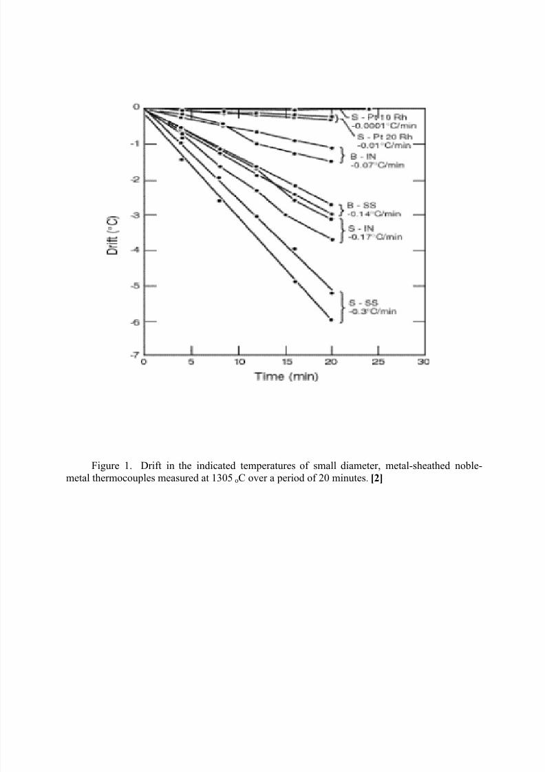
Three major problem areas associated with temperature measurement technology are; 1)uncertain, “drifting” temperature data, 2) short sensor life due to the failure of the internal
components of the temperature sensor and 3) short sensor life due to the failure of the protective
sheath material. An example of the drift that is associated with metal-sheathed noble-metalthermocouples measured at 1305
oC over a period of minutes is given in Figure 1. The drift in
temperature is directly associated with the type of sheathed material used to protect the
thermocouple.
8/8/2019 Advanced Silicide Based Materials - MoSi2
http://slidepdf.com/reader/full/advanced-silicide-based-materials-mosi2 3/13
When selecting a protective sheath material for a glass temperature sensor a number of factors need to be considered including; the chemical stability of the sheath material in the glass
processing environment (above the glass, below the glass and at the glass line), the potential
contamination of the glass from the sheath material, decalibration of the temperature sensor dueto impurity migration from the sheath material and the mechanical and thermal shock
performance of the sheath material in the aggressive glass melting process. The use of platinum
coatings on alumina (Al2O3) sheaths for thermocouples is a widely employed practice in the
glass industry. The cost associated with providing platinum coatings on the Al2O3 sheathmaterial can be prohibitively high when taking into consideration the infrastructure needed at the
glass plants to maintain and secure an inventory of available platinum. There are also issues
associated with improving the performance of the platinum coated Al2O3. The failure rate due tothermal shock of the thermocouples can be as high as 50%. The U.S. glass industry has been in
search of alternative materials that can replace platinum and still provide the durability and
performance needed to survive in an extremely corrosive glass environment.
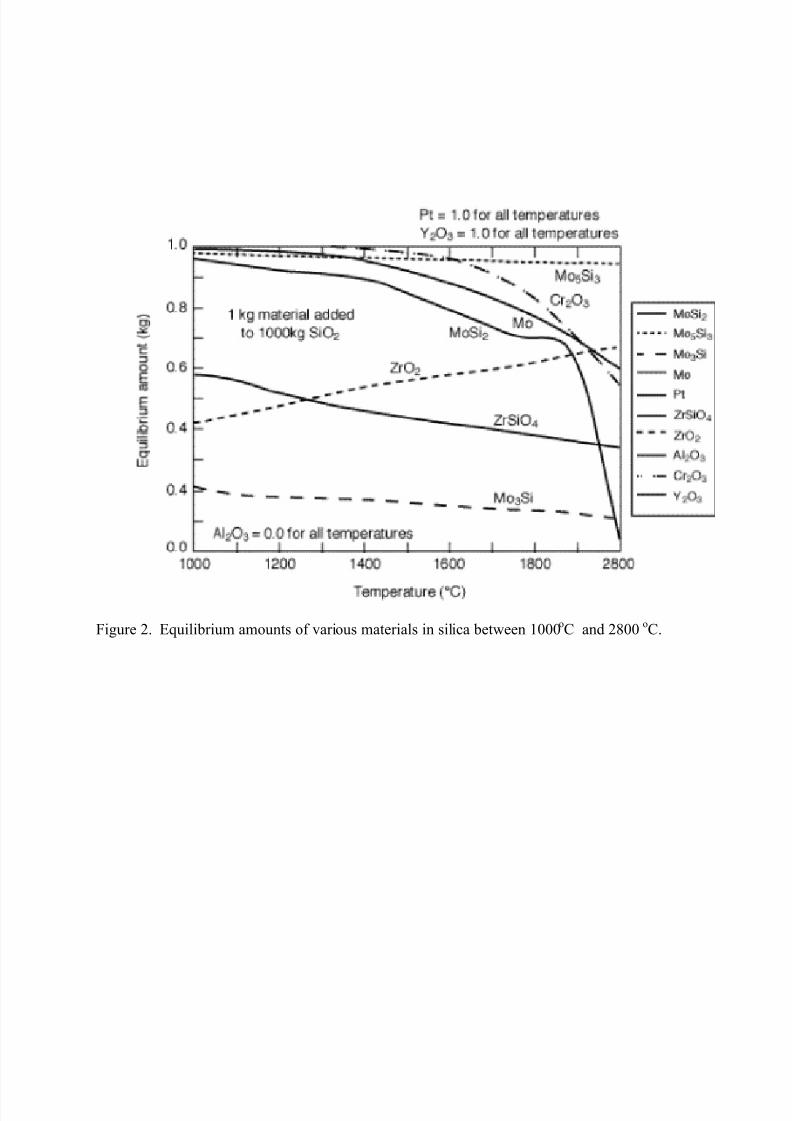
Investigations by Y.S. Park et al [3] have shown that molybdenum disilicide (MoSi2) has
similar performance properties in molten glass as some refractory materials that are currently
being used in glass processing applications. Above the glass line MoSi2 forms a protective SiO2
layer preventing oxidation of the material. Below the glass line molybdenum rich phases(Mo5Si3) can form which enhances the performance of the material when in contact with the
molten glass. A thermodynamic analysis of equilibrium amounts of various materials in silica between 1000
oC and 2800
oC is shown in Figure 2. From this analysis Pt, Mo5Si3, Cr 2O3, Mo
and MoSi2 are relatively stable when in contact with molten SiO2.
Plasma spraying has been demonstrated by a number of researchers [4,5,6,7] to be a cost
effective method for producing coatings and spray formed components of MoSi2 and MoSi2-
based composites. In this paper we will report on the use of plasma sprayed MoSi 2 as a potentialcoating over Al2O3 to replace platinum and the use of MoSi2-Al2O3 spray formed composites to
enhance the mechanical performance and damage tolerance of the protective sheath material.
3.0 Experimental
Atmospheric plasma spraying was used to produce MoSi2 coatings on Al2O3 thermocouplesheaths and layered and graded thermocouple sheaths of MoSi2 - Al2O3 composites. The plasma
spray equipment used included a Praxair Surface Technologies SG100 plasma torch and two
Model 1264 powder feed hoppers. The plasma torch was mounted on a Fanuc S10 6-axis robot.A LabView based computer control system was used to monitor and control the processing gases
and the powder hopper-dispensing rate. Details on how the powder hoppers can be controlled to
produce graded and layered microstructures are found in reference [8]. A closed end graphite
tube (12.7mm OD x 9.5 mm ID) was used as a substrate for producing the MoSi2-Al2O3
composite thermocouple sheaths. To determine the mechanical behavior of the graded MoSi2-
Al2O3 structures C-rings and four-point bend samples were machined from the material
deposited on the graphite rods. C-ring samples were wire electro-discharge machined (EDM) outof the sprayed tube samples. The C-rings had an OD of 25.93mm, an ID of 12.8mm and a width
of 10.76 mm. The critical b/(r o-r i) ratio was 1.64, within the required range of 1 to 4. The C-ring
samples were tested in diametrical compression using a hydraulic Instron test frame (Type 1331with an 8500 Plus controller and a 10kN load cell), at a cross-head speed of 0.125 mm/min
8/8/2019 Advanced Silicide Based Materials - MoSi2
http://slidepdf.com/reader/full/advanced-silicide-based-materials-mosi2 4/13
(strain rate ~ 0.316 x 10⁻⁴
s-1
). Machine compliance was corrected using a standard Al2O3 sample
of known stiffness. The C-ring samples were machined and tested in accordance with ASTMStandard C 1323-96. Four-point bend test samples 25mm long x 5mm wide x 2.5mm thick were
also machined from plasma sprayed composites. The samples were (EDM) machined and surface
ground (approximately .00254 mm per pass) using a 150 and 320 grit grinding wheel. Bendtesting was performed in an Instron machine using a cross-head speed of 0.5 mm/min. The
samples were tested in a hardened steel fixture which were supported on steel pins 19 mm apart.
Loading was accomplished by two steel pins 9.5 mm apart. The four-point bend tests were
carried out in accordance with ASTM standard C-1161/90. The maximum stress was calculatedusing the following equation:
σf = 3PL/4bd2
(1)
where σf is the maximum stress in the sample, P is the maximum load at which the sample
fractured, L is the support span length, b is the specimen width and d is the specimen thickness.
4.0 RESULTS
4.1 Layered Composites
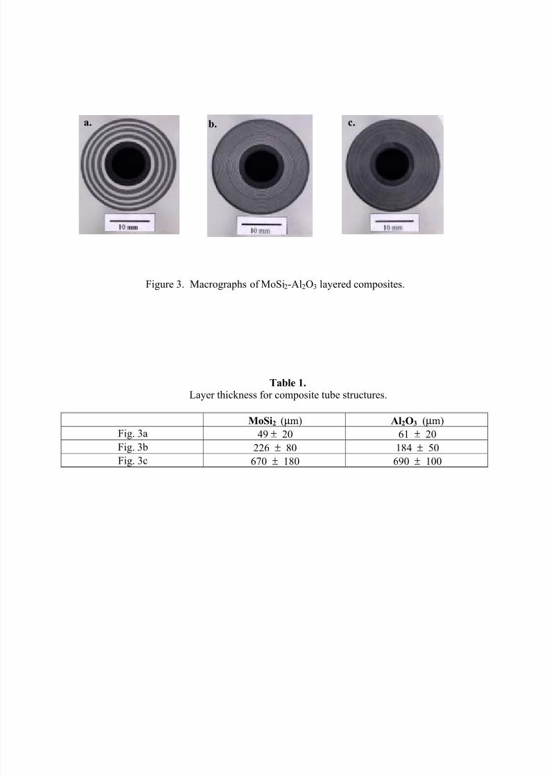
Macrographs demonstrating the flexibility of using atmospheric plasma spraying to produce
tubular layer composites of MoSi2-Al2O3 are shown in Figure 3. The white phase is the Al2O3
and the dark phase is MoSi2. Figure 3a, b and c show progressively thinner discrete layers of
both MoSi2 and Al2O3. The thickness of each layer is given in Table 1. Optimizing the
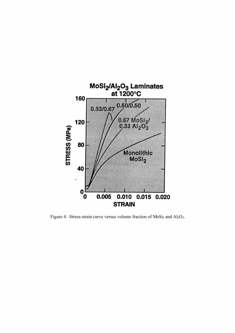
microstructure of the composite layered structure will require a better understanding of theinfluence of the layer thickness and spacing of each phase. Figure 4 shows the stress-strain
behavior of MoSi2-Al2O3 laminate composites tested at 1200oC with varying volume fractions
of each phase. Increasing the volume fraction of MoSi2 will decrease the strength of thecomposite but will improve the fracture energy (area under the stress-strain curve) of the
composite system. This improvement in fracture energy can be attributed to the brittle-to-ductiletransformation that occurs in MoSi2 at approximately 1000
oC [9]. For this composite system at
temperatures above 1000oC MoSi2 acts like a ductile reinforcement for Al2O3 improving its
damage tolerance at elevated temperatures. Investigations are currently being performed to
understand the influence of the layer thickness on the mechanical and thermal properties of the
composite and how this can effect the thermal shock behavior [10].
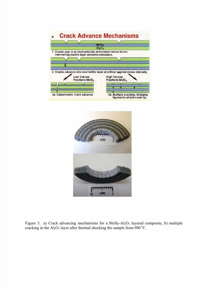
Crack mechanisms associated with a layered MoSi2-Al2O3 composite are illustrated in
Figure 5a. The advancement of a crack at elevated temperatures will depend on the layer thickness of the ductile MoSi2 layer. Under an initial applied stress, cracks will be introduced
stochastically in the Al2O3 layer. Crack advancement into the next brittle Al2O3 layer will occur
at some critical applied stress intensity. Catastrophic crack advancement through the compositelayers will be effected by the ability of the ductile MoSi2 layers to provide bridging ligaments,
crack deflection, and multiple cracking which can reduce the stress intensity at the tip of the
advancing crack. The cracking behavior of a MoSi2-Al2O3 composite after thermal shocking the
composite from 900oC to room temperature water is shown in Figure 5b. Multiple cracking
occurred in the Al2O3 layers. The sample did not catastrophically fail after the thermal shock
test.
8/8/2019 Advanced Silicide Based Materials - MoSi2
http://slidepdf.com/reader/full/advanced-silicide-based-materials-mosi2 5/13
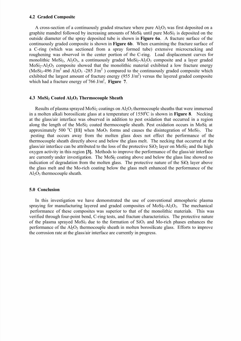
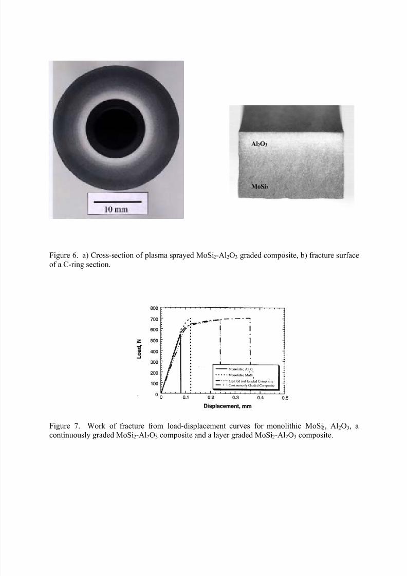
4.2 Graded Composite
A cross-section of a continuously graded structure where pure Al2O3 was first deposited on a
graphite mandrel followed by increasing amounts of MoSi2 until pure MoSi2 is deposited on the
outside diameter of the spray deposited tube is shown in Figure 6a. A fracture surface of thecontinuously graded composite is shown in Figure 6b. When examining the fracture surface of
a C-ring (which was sectioned from a spray formed tube) extensive microcracking and
roughening was observed in the center portion of the C-ring. Load displacement curves for
monolithic MoSi2, Al2O3, a continuously graded MoSi2-Al2O3 composite and a layer gradedMoSi2-Al2O3 composite showed that the monolithic material exhibited a low fracture energy
(MoSi2-496 J/m2
and Al2O3 -285 J/m2
) compared to the continuously graded composite which
exhibited the largest amount of fracture energy (955 J/m2) versus the layered graded composite
which had a fracture energy of 766 J/m2, Figure 7.
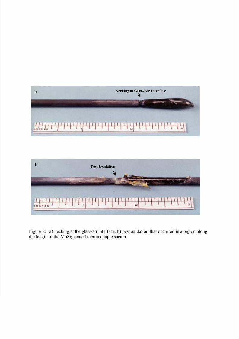
4.3 MoSi2 Coated Al2O3 Thermocouple Sheath
Results of plasma sprayed MoSi2 coatings on Al2O3 thermocouple sheaths that were immersed
in a molten alkali borosilicate glass at a temperature of 1550oC is shown in Figure 8. Necking
at the glass/air interface was observed in addition to pest oxidation that occurred in a regionalong the length of the MoSi2 coated thermocouple sheath. Pest oxidation occurs in MoSi2 at
approximately 500oC [11] when MoO3 forms and causes the disintegration of MoSi2. The
pesting that occurs away from the molten glass does not effect the performance of the
thermocouple sheath directly above and below the glass melt. The necking that occurred at the
glass/air interface can be attributed to the loss of the protective SiO2 layer on MoSi2 and the highoxygen activity in this region [3]. Methods to improve the performance of the glass/air interface
are currently under investigation. The MoSi2 coating above and below the glass line showed no
indication of degradation from the molten glass. The protective nature of the SiO2 layer abovethe glass melt and the Mo-rich coating below the glass melt enhanced the performance of the
Al2O3 thermocouple sheath.
5.0 Conclusion
In this investigation we have demonstrated the use of conventional atmospheric plasmaspraying for manufacturing layered and graded composites of MoSi2-Al2O3. The mechanical
performance of these composites was superior to that of the monolithic materials. This was
verified through four-point bend, C-ring tests, and fracture characteristics. The protective natureof the plasma sprayed MoSi2 due to the formation of SiO2 and Mo-rich phases enhances the
performance of the Al2O3 thermocouple sheath in molten borosilicate glass. Efforts to improve
the corrosion rate at the glass/air interface are currently in progress.
8/8/2019 Advanced Silicide Based Materials - MoSi2
http://slidepdf.com/reader/full/advanced-silicide-based-materials-mosi2 6/13
6.0 Acknowledgements
This research has been supported by the U.S. Department of Energy, Office of Industrial
Technologies, Advanced Industrial Materials Program, Glass Industry.
References
1. Report: Glass Technology Roadmap Workshop, Energetics Incorporated, April 24-25, 1997
pp. 21-29.
2. R.L. Anderson, Temperature: Its Measurements and Control in Science and Industry,American Institute of Physics, Ed. J.F. Schooley, Vol 5., (1982) 977-1007.
3. Y.S. Park, D.P. Butt, R. Castro, J. Petrovic, W. Johnson, Mat. Sci. and Eng.,
A261, 278-283 (1999).
4. R. Tiwari, H. Herman, and S. Sampath, “Vacuum Plasma Spraying of MoSi2 and its
Composites,” Mat. Sci. Eng., A155 95-100 (1992).
5. A. Newman, S. Sampath, and H. Herman, “Processing and Properties of MoSi2-SiC andMoSi2-Al2O3,” Mat. Sci. Eng., A261 252-260 (1999).
6. H. Kung, R.G. Castro, A.H. Bartlett, and J.J. Petrovic, “The Structure of Plasma Sprayed
MoSi2-Al2O3 Microlaminate Tubes,” Scripts Metall. Et. Mater., 32 [2] 179-183 (1995).
7. R.G. Castro, J.R. Hellman, A.E. Segall, and D.L. Shellman, “Fabrication and Testing of
Plasma-Sprayed Formed MoSi2 and MoSi2 Composite Tubes,” Mat. Res. Soc. Symp. Proc.,322 81-86 (1994).
8 M.I. Peters, R. U. Vaidya, R. G. Castro, J.J. Petrovic and K.J. Hollis,
FUNCTIONALLY GRADED MOSI2-AL2O3 TUBES FOR TEMPERATURESENSOR APPLICATIONS”
9. K. Ito, K. Matsuda, Y. Shirai, H. Inui, and M. Yamagucji, “Brittle-Ductile Behavior of Single Crystals of MoSi2,” Mat. Sci. Eng., A261 99-105 (1999).
10. Daniels Thesis
11. T.C. Chou and T.G. Nieh, “Pesting of the High-Temperature Intermetallic MoSi2,” JOM
[12] 15-21 (1993).
8/8/2019 Advanced Silicide Based Materials - MoSi2
http://slidepdf.com/reader/full/advanced-silicide-based-materials-mosi2 7/13
8/8/2019 Advanced Silicide Based Materials - MoSi2
http://slidepdf.com/reader/full/advanced-silicide-based-materials-mosi2 8/13
Figure 2. Equilibrium amounts of various materials in silica between 1000oC and 2800
oC.
8/8/2019 Advanced Silicide Based Materials - MoSi2
http://slidepdf.com/reader/full/advanced-silicide-based-materials-mosi2 9/13
Figure 3. Macrographs of MoSi2-Al2O3 layered composites.
Table 1.Layer thickness for composite tube structures.
MoSi2 (µm) Al2O3 (µm)
Fig. 3a 49 ± 20 61 ± 20
Fig. 3b 226 ± 80 184 ± 50
Fig. 3c 670 ± 180 690 ± 100
a. b. c.
8/8/2019 Advanced Silicide Based Materials - MoSi2
http://slidepdf.com/reader/full/advanced-silicide-based-materials-mosi2 10/13
Figure 4. Stress-strain curve versus volume fraction of MoSi2 and Al2O3.
8/8/2019 Advanced Silicide Based Materials - MoSi2
http://slidepdf.com/reader/full/advanced-silicide-based-materials-mosi2 11/13
Figure 5. a) Crack advancing mechanisms for a MoSi2-Al2O3 layered composite, b) multiple
cracking in the Al2O3 layer after thermal shocking the sample from 900oC.
a
8/8/2019 Advanced Silicide Based Materials - MoSi2
http://slidepdf.com/reader/full/advanced-silicide-based-materials-mosi2 12/13
Al2O3
MoSi2
Figure 6. a) Cross-section of plasma sprayed MoSi2-Al2O3 graded composite, b) fracture surface
of a C-ring section.
Figure 7. Work of fracture from load-displacement curves for monolithic MoSi2, Al2O3, a
continuously graded MoSi2-Al2O3 composite and a layer graded MoSi2-Al2O3 composite.
8/8/2019 Advanced Silicide Based Materials - MoSi2
http://slidepdf.com/reader/full/advanced-silicide-based-materials-mosi2 13/13
Figure 8. a) necking at the glass/air interface, b) pest oxidation that occurred in a region along
the length of the MoSi2 coated thermocouple sheath.
Pest Oxidationb
Necking at Glass/Air Interfacea