basic concepts and vbc 2000-c digital vibration control ... · basic concepts and vbc 2000-c...
TRANSCRIPT
VibroBlock® Feeder Systems
Basic Concepts and VBC 2000-C Digital Vibration Control
Functions

Copyright 2015 Arthur G. Russell Co., Inc. All rights reserved.
No part of this publication may be reproduced in any form (print, photocopy, microfilm, or other means, or electronically processed,
reproduced, or transmitted) without the written consent of Arthur G. Russell Co., Inc.
United States and foreign patents protect the machine and equipment illustrated and described in this manual. These illustrations and
specifications are not binding in detail. AGR reserves the right to make changes and improvements and to incorporate them in the machine as
conditions warrant.
VibroBlock® is a registered trademark of the Arthur G. Russell Co., Inc.
All brand names, product names or trademarks appearing in this manual belong to their respective holders.

Arthur G. Russell Co., Inc.
Basic Concepts and VBC 2000-C
Digital Vibration Control Functions Rev. 01 02/01/2016
Page 3 of 17
Revision History and Distribution
Document Name Date of Issue Details Distribution
Basic Concepts and VBC 2000-C Digital Vibration Control Functions
04/2002 Digital Copy Initial Release
Basic Concepts and VBC 2000-C Digital Vibration Control Functions
02/01/2016 Digital Copy Rev. 01

Arthur G. Russell Co., Inc.
Basic Concepts and VBC 2000-C
Digital Vibration Control Functions Rev. 01 02/01/2016
Page 4 of 17
This page left blank intentionally.
Arthur G. Russell Co., Inc.
Basic Concepts and VBC 2000-C
Digital Vibration Control Functions Rev. 01 02/01/2016
Page 5 of 17
Contents
Revision History and Distribution .................................................................................................................................................. 3
INTRODUCTION ................................................................................................................................................................ 7
Resonance ....................................................................................................................................................................... 7
Tuning ............................................................................................................................................................................. 8
Controllers ....................................................................................................................................................................... 8
SCR Drives ....................................................................................................................................................................... 9
Servo Control ................................................................................................................................................................... 9
Servo Concept ................................................................................................................................................................. 9
VBC 2000-C ......................................................................................................................................................................11
Transducers ................................................................................................................................................................... 11
Pulse Control ................................................................................................................................................................. 13
Load Current ................................................................................................................................................................. 15
Frequency ...................................................................................................................................................................... 16
Figures
FIGURE 1: FRONT PANEL BUTTONS .................................................................................................................................11
FIGURE 2: CORRECT TRANSDUCER INSTALLATION ...........................................................................................................12
FIGURE 3: ADJUST AMPLITUDE ........................................................................................................................................14
FIGURE 4: MOUNTED NAMEPLATE ..................................................................................................................................16

Arthur G. Russell Co., Inc.
Basic Concepts and VBC 2000-C
Digital Vibration Control Functions Rev. 01 02/01/2016
Page 6 of 17
This page left blank intentionally.

Arthur G. Russell Co., Inc.
Basic Concepts and VBC 2000-C
Digital Vibration Control Functions Rev. 01 02/01/2016
Page 7 of 17
INTRODUCTION
The following will explain some of the basics of vibration, and more specifically, how they relate to
VibroBlock feeders, tracks and bins. The importance of tuning and its relationship to the control
system will also be covered. These concepts will be explained in terms useful to the non-technical
person as well as the experienced feeder technician.
Resonance
Virtually everything in the world has resonance. If you strike an object, it will vibrate at some
frequency. This frequency is determined by many factors, but only those relating to the VibroBlock
will be examined. Pushing a child on a swing uses the same type of resonance that is present in a
VibroBlock system. The length of the chains and the weight of the child create a particular resonant
frequency. As long as the swing is pushed at the proper time, very little energy is required to keep
the swing moving. Stepping closer will force the swing to be pushed before it comes to a complete
stop. It will take more energy to keep the swing moving. This is an example of trying to move a
device that is higher than its resonant frequency. Stepping back a little from the original position will
waste some of the forward push while the swing is not contacted. This is an example of trying to
move a device that is lower than its resonant frequency. These examples are virtually the same as the
concepts used to tune a VibroBlock system.

Arthur G. Russell Co., Inc.
Basic Concepts and VBC 2000-C
Digital Vibration Control Functions Rev. 01 02/01/2016
Page 8 of 17
Tuning
Proper tuning is essential to the operation of all VibroBlock systems. A properly tuned VibroBlock
system will feed efficiently, run cool and use minimal electricity. The swing examples given above
could lead feeder technicians to believe that exact resonant tuning is the best approach. However,
this is not entirely true. Experience has shown that tuning a VibroBlock system approximately 1.5
cycles above line frequency provides the best performance and longest life.
When a VibroBlock system is run at its resonant frequency, it is so efficient that the system can
become unstable. Tuning slightly above frequency provides the equivalent of a slight friction on the
system, which enhances stability. Always tune a VibroBlock system above rather than below
frequency because tuning decays somewhat over time. Tuning at a frequency higher than 1.5 cycles
above line frequency may be done to increase load current. While this is not usually harmful, it can
cause some instability such as pulsations.
It is usually preferential to tune at approximately 1.5 cycles above line frequency. Tuning should be
done at a higher level than the highest amplitude ever anticipated to be run on that particular
VibroBlock system. This is important because resonant frequency drops as amplitude increases. If
tuned at lower amplitude initially and increased later, it could be too close to the line frequency,
which would trigger the tuning indicator light to go on due to a tuning fault.
Controllers
Various methods have been employed to maintain controllers used to drive vibratory equipment. The
simplest is the variable transformer and rectifier. This method provides adjustable half-wave DC
power to the vibrators. Servo feedback cannot be provided with this method in order to compensate
for load in the feeder bowl. The most popular controller is the SCR drive. SCR drives offer many
advantages including ease of incorporating servo control. This type of drive is used in all VibroBlock
controllers.

Arthur G. Russell Co., Inc.
Basic Concepts and VBC 2000-C
Digital Vibration Control Functions Rev. 01 02/01/2016
Page 9 of 17
Variable frequency controllers are also available, which enable running the feeder at its own resonant
frequency. While a variable frequency controller offers some advantages, it also has drawbacks. The
controls are generally much larger and more complex. Also, running two (2) vibratory devices on a
machine can cause significant vibration problems caused by the difference between the two (2)
frequencies. Running feeders and tracks at different frequencies can also cause part transfer
problems.
SCR Drives
The SCR is a silicon-controlled rectifier that changes AC current into DC. The SCR is unique for its
ability to be controlled. When the AC cycle is changed by turning on an SCR, it will electronically
control the amount of power going to the vibratory system in real time. VibroBlock controllers
typically turn on between 90° and 180° positive. SCR drives are small, simple and able to switch
large amounts of alternating current to direct current.
Servo Control
The most effective way of maintaining proper vibration over time is servo control. Servo control
incorporates some type of sensor to measure the vibration and report the data back to the controller.
The controller then acts on the data and adjusts the power output of the controller. Various devices
can be used to detect vibration including magnetic, proximity and photoelectric. The single-chip
accelerometer is the most accurate and dependable method of measuring vibration. This is the
method used in the latest series of VibroBlock controllers. These are the VBC 2000-C series of
controllers. The accelerometer assembly is referred to as the transducer.
Servo Concept
The basic servo concept used by VibroBlock controllers is similar to how cruise control functions in
an automobile. When the controller is activated, power output rapidly increases toward maximum
output. As the transducer senses vibration, it sends an increasing-voltage signal back to the
controller. When a user set vibration level is achieved, the transducer causes the controller to hold
the power output at that level. As the transducer continues to monitor vibration, it makes small
adjustments in power output to keep the vibration constant.

Arthur G. Russell Co., Inc.
Basic Concepts and VBC 2000-C
Digital Vibration Control Functions Rev. 01 02/01/2016
Page 10 of 17
This page left blank intentionally.

Arthur G. Russell Co., Inc.
Basic Concepts and VBC 2000-C
Digital Vibration Control Functions Rev. 01 02/01/2016
Page 11 of 17
VBC 2000-C
Transducers
As the transducer vibrates, it produces a low-voltage sine wave signal. The sine wave peaks
correspond to acceleration and deceleration of the VibroBlock. The controller stores the peak
positive voltage every cycle. The previously-stored signal is erased first, so the new stored signal has
no accumulated error. This stored signal is compared to a reference sine wave signal provided by the
user, and is retrieved from either the front panel buttons (Figure 1) or PLC interface.
Figure 1: Front Panel Buttons
Arthur G. Russell Co., Inc.
Basic Concepts and VBC 2000-C
Digital Vibration Control Functions Rev. 01 02/01/2016
Page 12 of 17
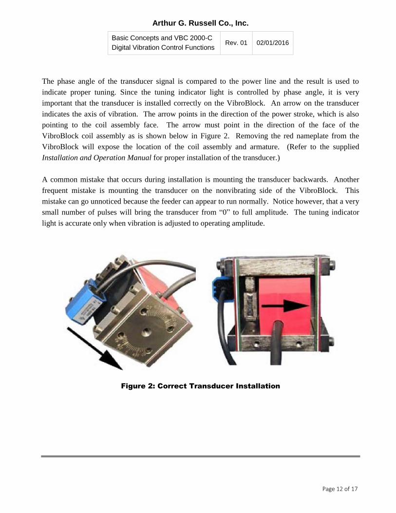
The phase angle of the transducer signal is compared to the power line and the result is used to
indicate proper tuning. Since the tuning indicator light is controlled by phase angle, it is very
important that the transducer is installed correctly on the VibroBlock. An arrow on the transducer
indicates the axis of vibration. The arrow points in the direction of the power stroke, which is also
pointing to the coil assembly face. The arrow must point in the direction of the face of the
VibroBlock coil assembly as is shown below in Figure 2. Removing the red nameplate from the
VibroBlock will expose the location of the coil assembly and armature. (Refer to the supplied
Installation and Operation Manual for proper installation of the transducer.)
A common mistake that occurs during installation is mounting the transducer backwards. Another
frequent mistake is mounting the transducer on the nonvibrating side of the VibroBlock. This
mistake can go unnoticed because the feeder can appear to run normally. Notice however, that a very
small number of pulses will bring the transducer from “0” to full amplitude. The tuning indicator
light is accurate only when vibration is adjusted to operating amplitude.
Figure 2: Correct Transducer Installation
Arthur G. Russell Co., Inc.
Basic Concepts and VBC 2000-C
Digital Vibration Control Functions Rev. 01 02/01/2016
Page 13 of 17
Pulse Control
VBC 2000-C controllers offer a unique method to control amplitude. Rather than utilizing a
potentiometer, amplitude is adjusted using push buttons or digital inputs. To increase output power,
press the Up/Down Arrow button repeatedly (Figure 3). To decrease output power, press the
Up/Down Arrow button repeatedly while simultaneously pressing and holding the Center button.
When the desired vibration amplitude is reached, press the Save button to store the setting in the
controller’s nonvolatile memory.
The functions of the Up/Down Arrow and Center buttons are also available via optically-isolated
digital inputs. These inputs allow remote adjustments from a PLC or other intelligent controller.
This method makes analog-type adjustments available without the cost of analog. Note that the save
function is not available when optically-isolated digital inputs are used. No setting above zero (0)
should be saved when using this control method.

Arthur G. Russell Co., Inc.
Basic Concepts and VBC 2000-C
Digital Vibration Control Functions Rev. 01 02/01/2016
Page 14 of 17
Figure 3: Adjust Amplitude

Arthur G. Russell Co., Inc.
Basic Concepts and VBC 2000-C
Digital Vibration Control Functions Rev. 01 02/01/2016
Page 15 of 17
To guarantee complete shutoff under all conditions when using pulse control, a 5-to-7 pulse deadband
(pulse is zero [0]) until vibration starts has been provided. The number of pulses required to achieve
amplitude will vary with each application. There are three (3) reasons for this.
1. The transducer measures amplitude at the VibroBlock, so real amplitude measurement on a
feeder bowl will depend on the distance from the transducer to the bowl rim.
2. The transducer is an accelerometer and acceleration increases with frequency. The basic
servo concept indicates that more pulses of amplitude must be set to overcome the larger
transducer signal at a higher frequency.
3. Tuning and power-to-weight ratio also have a small effect on actual amplitude.
Pulsing by the PLC provides a means to a soft start/stop of the feeder, so the vibration level can be
adjusted during operation. This may not be practical for some components, such as tracks and bins,
when instant on/off is desired. Contacts C1 and C2 are available to perform this function.
Load Current
The load current meter provides useful information. The numbers displayed represent actual direct
current flowing to the VibroBlock system. The units of measurement are amperes (A) to one (1)
decimal point. The meter does not display vibration amplitude, and the DC flow will not always
increase; it may decrease when output power increases. As vibration increases, the resonant tuning
frequency decreases slightly which makes the vibrator more efficient. This is why current can
decrease while amplitude increases.

Arthur G. Russell Co., Inc.
Basic Concepts and VBC 2000-C
Digital Vibration Control Functions Rev. 01 02/01/2016
Page 16 of 17
The load current reading can be used to detect overload on the VibroBlocks by comparing the reading
to the sum of the VibroBlock amperage that appears on the mounted nameplate. VibroBlock systems
typically run at 50 to 80 percent of full-load current. The load current is a function of the overall
power-to-weight ratio, as well as the tuning of the system. Record the load current on a new system
and recheck it periodically. Doing so can provide early warning of potential problems. Potential
problems include broken springs, loose or broken screws, or weight added or removed from the
system.
Frequency
VBC 2000-C controls are available for 120 VAC and 50 or 60 Hz power sources. Check the
mounted nameplate for the correct application (Figure 4).
Figure 4: Mounted Nameplate

Arthur G. Russell Co., Inc.
750 Clark Avenue, P.O. Box 237, Bristol, CT 06011-0237
Phone (860) 583-4109 Fax (860) 583-0686
www.arthurgrussell.com