cable supported barrel vault structure system …868 cable supported barrel vault structure system...
TRANSCRIPT
Advanced Steel Construction Vol. 6, No. 3, pp. 867-878 (2010) 867
CABLE SUPPORTED BARREL VAULT STRUCTURE SYSTEM AND RESEARCH ON MECHANICS FEATURE
Zhihua Chen1,*, Wentao Qiao2 and Xiangyu Yan3
1Professor, School of Civil Engineering, TianJin University, China
2PhD. Student, School of Civil Engineering, TianJin University, China 3PhD. Student, School of Civil Engineering, TianJin University, China
*(Corresponding author: E-mail: [email protected])
Received: 27 April 2009; Revised: 10 December 2009; Accepted: 22 December 2009
ABSTRACT: A new prestressed spatial steel structure system--cable supported barrel vault structure system is proposed in this paper. Firstly, the prestress design method for the structure is proposed. Then, we present in-depth analysis on the proposed structure. Research results suggest that the cable supported barrel vault is an efficient spatial steel structure system with improved rigidity, reduced horizontal arch thrust and well controlled horizontal displacement. The influence of several key parameters on the mechanics characteristics of the cable supported barrel vault is evaluated as well. The following conclusions are drawn from our study: (i) the impact of the rise-span ratio on the mechanics characteristics is significant, so the rise-span ratio should be designed properly. Values from 0.08 to 0.12 are suggest; (ii) the influence of the sag-span ratio is also great. The sag-span ratio with range from 0.02 to 0.06 is suggested; (iii) the impact of the strut number on the mechanics characteristics is small. The strut number is usually determined by the span of the structure. Generally speaking, the longer the span is the larger the strut number should be. Struts should be used as few as possible while meeting the safe standards, but the strut number should be more than one.
Keywords: Cable supported barrel vault; beam string structure; cylindrical latticed shell; rise-span ratio; sag-span ratio; strut number
1. INTRODUCTION Cylindrical latticed shell (Dong and Yao [1], Wang and Li [2], He et al. [3]) has been widely used in spatial structure projects due to its desirable merits such as beautiful fabrication, reasonable mechanics characteristics, mathematical tractability design method, and automatic machining, etc. However, considering that the out-plane stability of the structure itself is poor, it is very difficult for the single-layer or thin double-layer cylindrical latticed shell to span a long distance, As for the thick double-layer or multi-layer cylindrical latticed shell, it is flawed by the following demerits: (1) Too much steel is required when a latticed shell is very thick, which makes it cost-ineffective. (2) The lower supporting structures of the latticed shell such as columns and frames may be overloaded because of the big horizontal arch thrust (i.e., the transverse constraint reactions). (3) The fabrication and construction of joints is complicated since too many rods converge on a joint. (4) Long rods in a thick latticed shell complicates the site assembly.
The Hong Kong Institute of Steel Construction www.hkisc.org
868 Cable Supported Barrel Vault Structure System and Research on Mechanics Feature
In order to overcome these mentioned drawbacks above, a new-style prestressed spatial steel structure--cable supported barrel vault structure system (abbr. CSBVSS) is proposed in this paper inspired by cable supported structure system such as beam string structure (Masao and Kurasiro [4], Masao [5], Masao and Ohtake [6], Saitoh and Okasa [7], Wu [8], Xue and Liu [9]) and suspendome (Kawaguchi et al. [10], Tatemichi et al. [11], Chen and Li [12], Kang et al. [13], Kitipornchai et al. [14]), the proposed CSBVSS is composed of a single-layer or thin double-layer cylindrical latticed shell, struts and cables. On the one hand, the rigidity and the out-plane stability of the proposed structure are improved because of the action of struts and cables, consequently, the problem of the span is solved; on the other hand, less steel is used for the single-layer or the thin double-layer cylindrical latticed shell, which makes it cost-efficient and reduces the construction difficulty considerably as well. Moreover, the horizontal arch thrust is reduced effectively by the prestressed cables, so the heavy burden on the lower supporting structures is released significantly. 2. FABRICATION OF CABLE SUPPORTED BARREL VAULT STRUCTURE
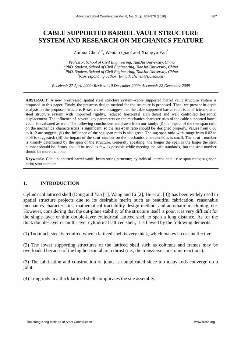
SYSTEM As shown in Figure 1, the proposed cable supported barrel vault structure is composed of a upper cylindrical latticed shell, lower cables and middle struts. The struts are placed vertically along the span direction. The lower end of the struts is linked by a cable via dead joints and the upper end is attached to the upper latticed shell by a pin roll joint. The two ends of the cable are linked with the latticed shell by anchor joints, which are set up in the place of supports.
Figure 1. Cable supported Barrel Vault Structure For the upper latticed shell of the cable supported barrel vault structure, the single-layer or the thin double-layer cylindrical latticed shell is usually used. The span, grid pattern and grid size are determined by demands of the architecture. As for the pattern of the single-layer latticed shell, single-rib orthogonal latticed grids, cross-rib orthogonal latticed grids, lamella latticed grids, or three-way latticed grids can be used; while the thin double-layer latticed shell can adopt two-way orthogonal latticed grids, two-way diagonal latticed grids, orthogonal square pyramid spatial grids, diagonal square pyramid spatial grids, orthogonal square pyramid spatial grids with openings, or square pyramid spatial grids of checkerboard pattern. The number of vertically placed struts along the span direction is determined by the span and optimized by calculation. The cables are set up along the longitudinal direction with the space between two or multiple grids, which is decided by practical conditions. Moreover, the cables should have certain sag. It can be seen in Figure 1 that single-rib orthogonal latticed grids are adopted in the demonstration model and three struts are placed.
Zhihua Chen, Wentao Qiao and Xiangyu Yan 869
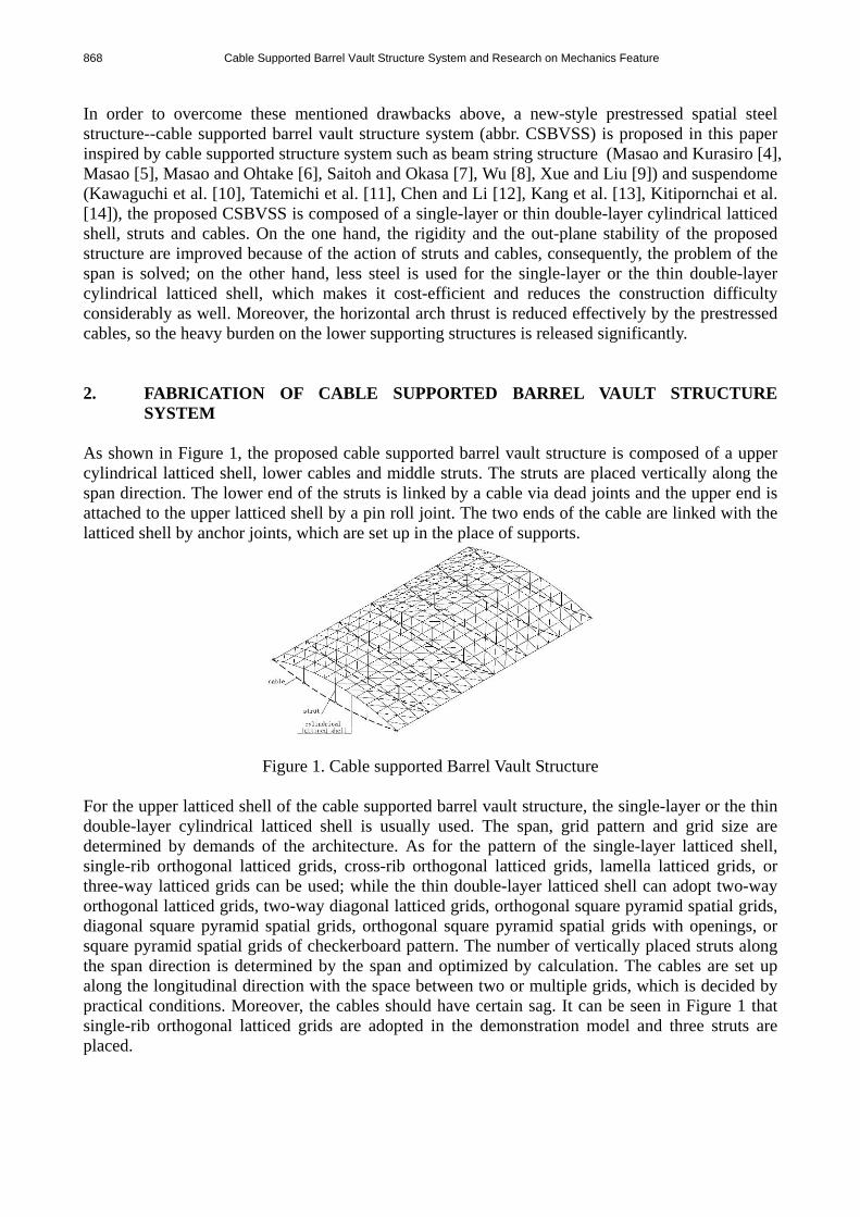
3. PRESTRESS DESIGN The peripheral restriction, in the cable supported barrel vault structure, is usually the spatial pin, i.e., transverse restriction of one side of the structure is released, so the structure can slide freely along this direction, therefore, the huge horizontal arch thrust induced by the cylindrical latticed shell is released, which, of course, causes huge transverse displacement, however, this displacement can be controlled due to the action of cables. From the analysis above, it is easy to find the prestress design principle of the cable supported barrel vault structure. The transverse displacement of each support of the structure (considering the symmetry of this structure system, the transverse displacement of each pin support is similar, so the maximum displacement can be used as the representative value, if it is zero or close to zero, all the transverse displacement can be considered zero or close to zero) is reduced to zero or close to zero by the action of prestressed cables, the detail process is introduced as follows.
n-1 n4321
Figure 2. Cable Disposition
The cable disposition of the cable supported barrel vault is shown in Figure 2. Firstly, the prestress is not imposed, i.e., the prestress value of each cable is set to zero, subject to the roof live load and dead weight of the structure, the forces of the cables are calculated as:
nn NNNNNNN ,,,,,, 14321 . Then, N is updated by the calculated prestress of each cable,
the structure is re-analyzed, and the transverse displacement of each support of the structure is figured out. Updating the value of N and recalculating again, this process is repeated and terminated until the displacement reaches zero or a certain predefined threshold, the calculated prestress N put on the cables is the target value. When the cable supported barrel vault is constructed, the steel latticed shell, struts and cables are fixed and supported by the temporary braces. Then the cables are tensioned, according to the mechanical balance principle, the genuine initial prestress of cable is the calculated stress of the cable with the target value put into the cable and the dead weight imposed on the structure. It is worth noting that the geometry nonlinearity of the structure should be taken into account during the calculation process above. The whole process can be carried out by general finite element analysis software such as ANSYS, ABAQUS, Sap, Midas/gen etc.. In the following section, a practical project employing the proposed cable supported barrel vault structure is presented as an example, the prestress design of which is carried out by Midas/gen according to the prestress design method proposed above. 3.1 Example Analysis The project analyzed in this paper is a textile workshop roof, which is the first cable supported barrel vault structure in China. It is 410m long and divided into four parts with span of 50m. One part of them, 116.2m long, is analyzed. According to the demand of the architecture, the rise of this cable supported barrel vault structure is 4.3m, and the sag is 0.7m. Three-way latticed grids are used for the upper single-layer latticed shell, and the grid size is 4.5m. For the rod section, five types of sections are selected, includingΦ180x6,Φ203x8,Φ245x8,Φ299x8 andΦ325x10. While
870 Cable Supported Barrel Vault Structure System and Research on Mechanics Feature
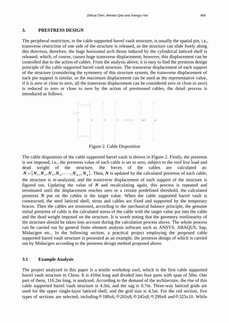
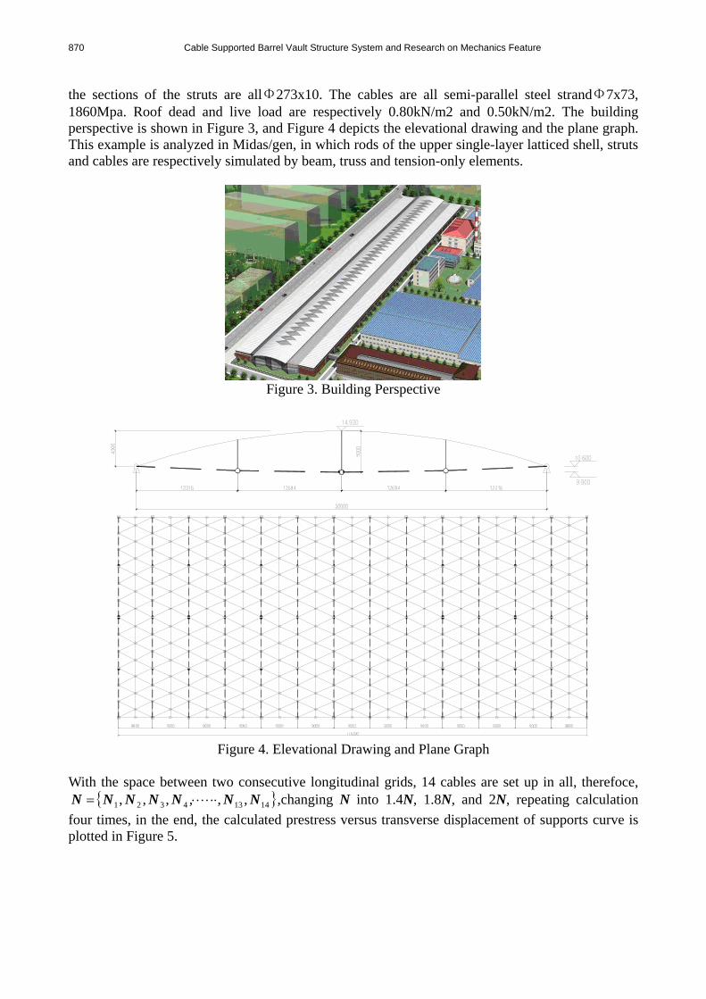
the sections of the struts are allΦ273x10. The cables are all semi-parallel steel strandΦ7x73, 1860Mpa. Roof dead and live load are respectively 0.80kN/m2 and 0.50kN/m2. The building perspective is shown in Figure 3, and Figure 4 depicts the elevational drawing and the plane graph. This example is analyzed in Midas/gen, in which rods of the upper single-layer latticed shell, struts and cables are respectively simulated by beam, truss and tension-only elements.
Figure 3. Building Perspective
Figure 4. Elevational Drawing and Plane Graph
With the space between two consecutive longitudinal grids, 14 cables are set up in all, therefoce,
14134321 ,,,,,, NNNNNNN ,changing N into 1.4N, 1.8N, and 2N, repeating calculation
four times, in the end, the calculated prestress versus transverse displacement of supports curve is plotted in Figure 5.
Zhihua Chen, Wentao Qiao and Xiangyu Yan 871
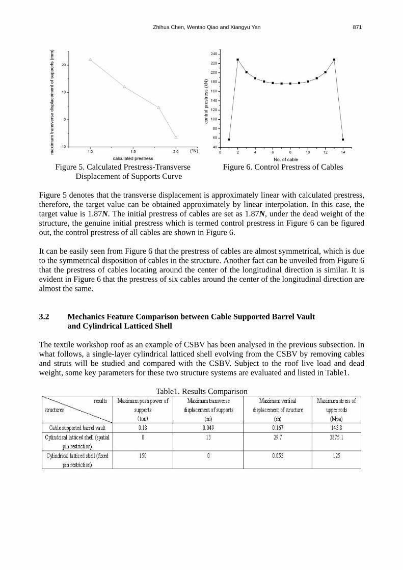
Figure 5. Calculated Prestress-Transverse Figure 6. Control Prestress of Cables
Displacement of Supports Curve Figure 5 denotes that the transverse displacement is approximately linear with calculated prestress, therefore, the target value can be obtained approximately by linear interpolation. In this case, the target value is 1.87N. The initial prestress of cables are set as 1.87N, under the dead weight of the structure, the genuine initial prestress which is termed control prestress in Figure 6 can be figured out, the control prestress of all cables are shown in Figure 6. It can be easily seen from Figure 6 that the prestress of cables are almost symmetrical, which is due to the symmetrical disposition of cables in the structure. Another fact can be unveiled from Figure 6 that the prestress of cables locating around the center of the longitudinal direction is similar. It is evident in Figure 6 that the prestress of six cables around the center of the longitudinal direction are almost the same. 3.2 Mechanics Feature Comparison between Cable Supported Barrel Vault and Cylindrical Latticed Shell The textile workshop roof as an example of CSBV has been analysed in the previous subsection. In what follows, a single-layer cylindrical latticed shell evolving from the CSBV by removing cables and struts will be studied and compared with the CSBV. Subject to the roof live load and dead weight, some key parameters for these two structure systems are evaluated and listed in Table1.
Table1. Results Comparison
872 Cable Supported Barrel Vault Structure System and Research on Mechanics Feature
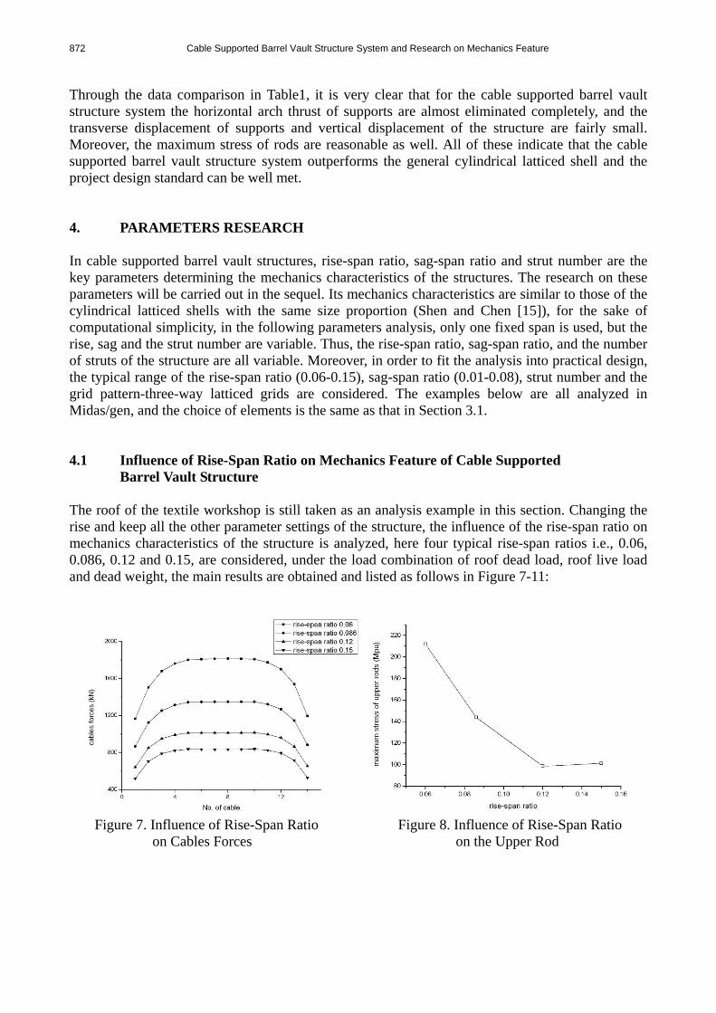
Through the data comparison in Table1, it is very clear that for the cable supported barrel vault structure system the horizontal arch thrust of supports are almost eliminated completely, and the transverse displacement of supports and vertical displacement of the structure are fairly small. Moreover, the maximum stress of rods are reasonable as well. All of these indicate that the cable supported barrel vault structure system outperforms the general cylindrical latticed shell and the project design standard can be well met. 4. PARAMETERS RESEARCH In cable supported barrel vault structures, rise-span ratio, sag-span ratio and strut number are the key parameters determining the mechanics characteristics of the structures. The research on these parameters will be carried out in the sequel. Its mechanics characteristics are similar to those of the cylindrical latticed shells with the same size proportion (Shen and Chen [15]), for the sake of computational simplicity, in the following parameters analysis, only one fixed span is used, but the rise, sag and the strut number are variable. Thus, the rise-span ratio, sag-span ratio, and the number of struts of the structure are all variable. Moreover, in order to fit the analysis into practical design, the typical range of the rise-span ratio (0.06-0.15), sag-span ratio (0.01-0.08), strut number and the grid pattern-three-way latticed grids are considered. The examples below are all analyzed in Midas/gen, and the choice of elements is the same as that in Section 3.1. 4.1 Influence of Rise-Span Ratio on Mechanics Feature of Cable Supported Barrel Vault Structure The roof of the textile workshop is still taken as an analysis example in this section. Changing the rise and keep all the other parameter settings of the structure, the influence of the rise-span ratio on mechanics characteristics of the structure is analyzed, here four typical rise-span ratios i.e., 0.06, 0.086, 0.12 and 0.15, are considered, under the load combination of roof dead load, roof live load and dead weight, the main results are obtained and listed as follows in Figure 7-11:
Figure 7. Influence of Rise-Span Ratio Figure 8. Influence of Rise-Span Ratio
on Cables Forces on the Upper Rod
Zhihua Chen, Wentao Qiao and Xiangyu Yan 873
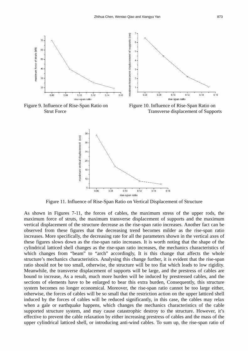
Figure 9. Influence of Rise-Span Ratio on Figure 10. Influence of Rise-Span Ratio on Strut Force Transverse displacement of Supports
Figure 11. Influence of Rise-Span Ratio on Vertical Displacement of Structure
As shown in Figures 7-11, the forces of cables, the maximum stress of the upper rods, the maximum force of struts, the maximum transverse displacement of supports and the maximum vertical displacement of the structure decrease as the rise-span ratio increases. Another fact can be observed from these figures that the decreasing trend becomes milder as the rise-span ratio increases. More specifically, the decreasing rate for all the parameters shown in the vertical axes of these figures slows down as the rise-span ratio increases. It is worth noting that the shape of the cylindrical latticed shell changes as the rise-span ratio increases, the mechanics characteristics of which changes from “beam” to “arch” accordingly, It is this change that affects the whole structure’s mechanics characteristics. Analysing this change further, it is evident that the rise-span ratio should not be too small, otherwise, the structure will be too flat which leads to low rigidity. Meanwhile, the transverse displacement of supports will be large, and the prestress of cables are bound to increase, As a result, much more burden will be induced by prestressed cables, and the sections of elements have to be enlarged to bear this extra burden, Consequently, this structure system becomes no longer economical. Moreover, the rise-span ratio cannot be too large either, otherwise, the forces of cables will be so small that the restriction action on the upper latticed shell induced by the forces of cables will be reduced significantly, in this case, the cables may relax when a gale or earthquake happens, which changes the mechanics characteristics of the cable supported structure system, and may cause catastrophic destroy to the structure. However, it’s effective to prevent the cable relaxation by either increasing prestress of cables and the mass of the upper cylindrical latticed shell, or introducing anti-wind cables. To sum up, the rise-span ratio of
874 Cable Supported Barrel Vault Structure System and Research on Mechanics Feature
the cable supported barrel vault structure should be selected appropriately. If the architecture permits, values ranging from 0.08 to 0.12 are suggested. 4.2 Influence of Sag-Span Ratio on Mechanics Feature of
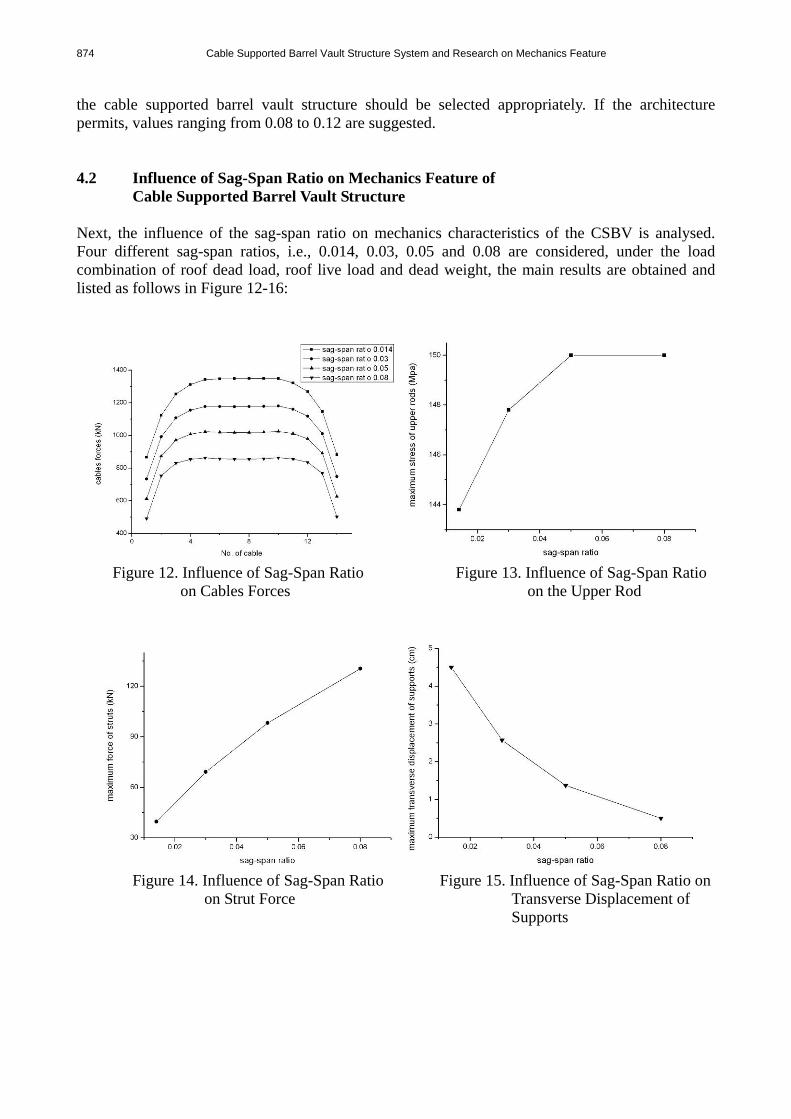
Cable Supported Barrel Vault Structure Next, the influence of the sag-span ratio on mechanics characteristics of the CSBV is analysed. Four different sag-span ratios, i.e., 0.014, 0.03, 0.05 and 0.08 are considered, under the load combination of roof dead load, roof live load and dead weight, the main results are obtained and listed as follows in Figure 12-16:
Figure 12. Influence of Sag-Span Ratio Figure 13. Influence of Sag-Span Ratio
on Cables Forces on the Upper Rod
Figure 14. Influence of Sag-Span Ratio Figure 15. Influence of Sag-Span Ratio on
on Strut Force Transverse Displacement of Supports
Zhihua Chen, Wentao Qiao and Xiangyu Yan 875
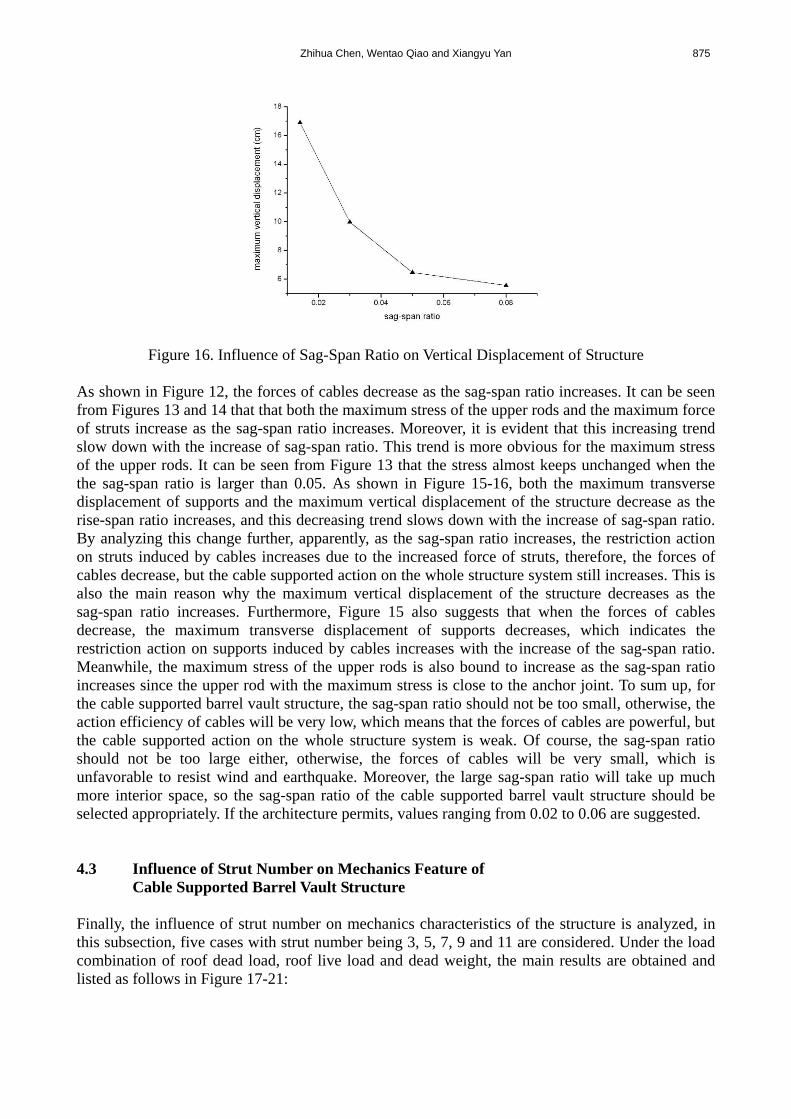
Figure 16. Influence of Sag-Span Ratio on Vertical Displacement of Structure As shown in Figure 12, the forces of cables decrease as the sag-span ratio increases. It can be seen from Figures 13 and 14 that that both the maximum stress of the upper rods and the maximum force of struts increase as the sag-span ratio increases. Moreover, it is evident that this increasing trend slow down with the increase of sag-span ratio. This trend is more obvious for the maximum stress of the upper rods. It can be seen from Figure 13 that the stress almost keeps unchanged when the the sag-span ratio is larger than 0.05. As shown in Figure 15-16, both the maximum transverse displacement of supports and the maximum vertical displacement of the structure decrease as the rise-span ratio increases, and this decreasing trend slows down with the increase of sag-span ratio. By analyzing this change further, apparently, as the sag-span ratio increases, the restriction action on struts induced by cables increases due to the increased force of struts, therefore, the forces of cables decrease, but the cable supported action on the whole structure system still increases. This is also the main reason why the maximum vertical displacement of the structure decreases as the sag-span ratio increases. Furthermore, Figure 15 also suggests that when the forces of cables decrease, the maximum transverse displacement of supports decreases, which indicates the restriction action on supports induced by cables increases with the increase of the sag-span ratio. Meanwhile, the maximum stress of the upper rods is also bound to increase as the sag-span ratio increases since the upper rod with the maximum stress is close to the anchor joint. To sum up, for the cable supported barrel vault structure, the sag-span ratio should not be too small, otherwise, the action efficiency of cables will be very low, which means that the forces of cables are powerful, but the cable supported action on the whole structure system is weak. Of course, the sag-span ratio should not be too large either, otherwise, the forces of cables will be very small, which is unfavorable to resist wind and earthquake. Moreover, the large sag-span ratio will take up much more interior space, so the sag-span ratio of the cable supported barrel vault structure should be selected appropriately. If the architecture permits, values ranging from 0.02 to 0.06 are suggested. 4.3 Influence of Strut Number on Mechanics Feature of Cable Supported Barrel Vault Structure Finally, the influence of strut number on mechanics characteristics of the structure is analyzed, in this subsection, five cases with strut number being 3, 5, 7, 9 and 11 are considered. Under the load combination of roof dead load, roof live load and dead weight, the main results are obtained and listed as follows in Figure 17-21:

876 Cable Supported Barrel Vault Structure System and Research on Mechanics Feature
Figure 17. Influence of Strut Number Figure 18. Influence of Strut Number
on Cables Forces on the Upper Rod
Figure 19. Influence of Strut Number on Strut Force Figure 20. Influence of Strut Number on
Transverse Displacement of Supports
Figure 21. Influence of Strut Number on Vertical Displacement of Structure
As shown in Figure 17, as the strut number increases the forces of cables almost keep the same, and the maximum change is less than 2.5%. It can be seen from Figure 18 and 19 that both the maximum stress of the upper rods and the maximum force of struts decreases as the strut number increases. Similar as Figure 8 and 9, their decreasing rate slows down with the increase of strut number. This phenomenon is more obvious for the influence on the maximum stress of the upper rods. Moreover, the stress almost does not change as the strut number exceeds 5, and the maximum

Zhihua Chen, Wentao Qiao and Xiangyu Yan 877
change is less than 1.5%. Also, the maximum force of struts almost remains unchanged when the strut number exceeds 9. As demonstrated in Figure 20 and 21, the maximum transverse displacement of supports and the maximum vertical displacement of the structure both increase with the increase of the strut number, For the strut number ranging from 5 to 9, both displacements seem unchanged. However, when the strut number is more than 9, both of them begin to increase again. The following facts can be also observed that (i) the impact of strut number on the forces of cables is weak; (ii) only when the strut number is less than 3, the increase of the strut number makes the latticed shell bear load more evenly, in consequence, the maximum stress of the upper rods will be reduced, but this decreasing is very limited, and as the strut number augments this effect becomes weaker. If the strut number increases excessively, as a result, the dead weight of the structure will increase as well, which leads to the increase of the displacement of the structure. Therefore, it is not wise to improve the mechanics behaviors of the upper latticed shell by increasing the strut number excessively. Furthermore, in the cable supported barrel vault, the strut number is usually more than one, when only one strut is used, the structure is usually unstable or the displacement of the strut is too large, so the calculation becomes hard to converge. To sum up, the strut number is usually decided by the span and must be more than one. However, struts should be used as less as possible if the structure permits. 5. CONCLUSIONS A cable supported barrel vault structure has been proposed and analysed in this paper. The research results indicate that it is an efficient spatial structure system and the rigidity of the whole structure system is advanced due to the action of struts and cables. The horizontal arch thrust of supports can almost be eliminated completely, and the horizontal displacement is still under control. By investigating the influence of rise-span ratio, sag-span ratio and strut number on the mechanics characteristics of the structure, the following conclusions have been drawn: (1) The influence of the rise-span ratio on the proposed CSBV is significant. Reducing the rise-span ratio will decrease the rigidity of the structure and increase the transverse displacements of supports. It has been shown that increasing the cables prestress is not a good solution to solve these problems above, since it makes structure system uneconomical. Moreover, the increase of the rise-span ratio weakens the cable supported action. Meanwhile, it is also unfavorable to resist wind and earthquake, due to the reduced cable forces. Therefore, the choice of the rise-span ratio should be appropriate, the proper value from 0.08 to 0.12 has been suggested. (2) The impact of the sag-span ratio is also great. Reducing the sag-span ratio will lower the action efficiency of cables, which means that the forces of cables are powerful, but the cable supported action is weak, furthermore, increasing the sag-span ratio strengthens cable supported action but weakens cables forces, which is unfavorable as well to resist wind and earthquake. Large sag-span ratio takes up much much space, so the sag-span ratio should be designed appropriate. The proper value from 0.02 to 0.06 has been suggested.
878 Cable Supported Barrel Vault Structure System and Research on Mechanics Feature
(3) The influence of the strut number is small. The strut number is usually decided by the span of the structure, and struts should be used as few as possible under the condition of meeting standards. But the strut number must be more than one, otherwise, the structure is usually unstable or the displacement of the strut is too large, which eventually makes the calculation hard to converge. REFERENCES [1] Dong, S.L. and Yao, J., “The Future and Prospect of Latticed Shell Structures”, Spatial
Structures, 1994, Vol. 1, No. 1, pp. 3–10. [in Chinese] [2] Wang, B.B. and Li, Y.Y., “A Theoretical Study of Super-Span Latticed Shells”, Journal of
Constructional Steel Research, 1999, Vol. 51, pp. 287–96. [3] He, Y.J., Zhou, X.H. and Dong, S.L., “Research on Static and Stability Properties of Single
Layer Latticed Intersected Cylindrical Shell”, Journal of Hunan University (Nature Sciences), 2004, Vol. 31, No. 4, pp. 45–50. [in Chinese]
[4] Masao, Saitoh and Kurasiro Tosiya, “A Study on Structural Behaviors of Beam String Structure”, Summaries of Technical Papers of Annual Meeting Architectural Institute of Japan [C], Tokyo, Japan, B 1.1985, pp. 280–284.
[5] Masao, Saitoh, “A Study on Structural Planning of Radial Type Beam String Structures”, Summaries of Technical Papers of Annual Meeting Architectural Institute of Japan [C], Tokyo, Japan, B 1.1988, pp. 1365–1366.
[6] Masao, Saitoh and Ohtake, Tohru, “A Study on Beam String Structure with Flat Circular Arch”, Summaries of Technical Papers of Annual Meeting Architectural Institute of Japan [C], Tokyo, Japan, B 1.1988, pp. 1369–1374.
[7] Masao, Saitoh and Okasa, Akira, “The Role of String in Hybrid String Structure”, Engineering Structures, 1999, Vol. 21, No. 8, pp. 756–69.
[8] Wu, M.E., “Analytical Method for the Lateral Buckling of the Struts in Beam String Structures”, Engineering Structures, 2008, Vol. 30, No. 9, pp. 2301–2310.
[9] Xue, W.C. and Liu, S., “Design Optimization and Experimental Study on Beam String Structures”, Journal of Constructional Steel Research, 2008, No. 9, pp. 1-11.
[10] Kawaguchi, Mamoru, Abe, Masaru and Tatemichi, Ikuo, “Design, Tests and Realization of "Suspen-Dome" System”, Journal of the IASS, 1999, Vol. 40, No. 131, pp. 179-192.
[11] Tatemichi, I., Hatato, T. and Anma, Y., et al., “Vibration Tests on a Full-Size Suspen-Dome Structure”, International Journal of Space Structure, 1997, Vol. 12, No. 3 & 4, pp. 217-224.
[12] Chen, Z.H. and Li, Y., “Parameter Analysis on Stability of a Suspen-Dome”, International Journal of Space Structure, 2005, Vol. 20, No. 2, pp. 115-124.
[13] Kang, W.J., Chen, Z.H. and Lam, Heung-Fai, et al., “Analysis and Design of the General and Outmost-Ring Stiffed Suspen-Dome Structures”, Engineering Structures, Vol. 25, 2003, pp. 1685-1695.
[14] Kitipornchai, S., Kang, W.J. and Lam, Heung-Fai, et al., “Factors Affecting the Design and Construction of Lamella Suspen-Dome Systems”, Journal of Constructional Steel Research, Vol. 61, 2005, pp. 764-785.
[15] Shen, S.Z. and Chen, X., “Stability of the Shell Structures”, Beijing: Science Press, 1999. [in Chinese]