chapter 11 powerplant hose assemblies test - faa fire … · 11-1 chapter 11 powerplant hose...
TRANSCRIPT
11-1
Chapter 11Powerplant Hose Assemblies Test
11.1 Scope
11.1.1 This test method is used to determine the fire resistance of high-temperature hose assemblies used indesignated fire zones to damage due to flame and vibration for showing compliance with TSO C42,C53A, and C75.
11.1.2 The requirements and procedures of this test method vary according to hose materials and hoseassembly application.
11.2 Definitions
11.2.1 Designated Fire Zone
A designated fire zone is defined as a region of the aircraft, such as engine and auxiliary power unitcompartments designated to require fire detection and extinguishing equipment, and as appropriate,the use of materials that are fire resistant or fireproof.
11.2.2 Fireproof
Per FAR Part 1, (found in Subchapter ADefinitions, Part IDefinitions and Abbreviations) “indesignated fire zones means the ability of materials to withstand the heat from a severe fire ofextended duration at least as well as steel in dimensions appropriate for their purpose.”
Powerplant hose assemblies are demonstrated to be fireproof by meeting the requirements of this testfor a flame exposure time of 15 minutes.
11.2.3 Fire Resistant
Per FAR Part 1, (found in Subchapter ADefinitions, Part IDefinitions and Abbreviations) “withrespect to fluid carrying lines, fluid system parts, wiring, air ducts, fittings, and powerplant controlsmeans the capacity to perform the intended functions under the heat and other conditions likely tooccur when there is a fire at the place concerned.”
Powerplant hose assemblies are demonstrated to be fire resistant by meeting the requirements of thistest for a flame exposure time of 5 minutes.
11.2.4 Class A Hose Assembly
A class A hose assembly is defined as a hose assembly capable of withstanding exposure to this firetest procedure for 5 minutes without failure (e.g., leaking circulating oil) per TSO C53a.
11.2.5 Class B Hose Assembly
A class B hose assembly is defined as a hose assembly capable of withstanding exposure to this firetest procedure for 15 minutes without failure (e.g., leaking circulating oil) per TSO C53a.
11.2.6 Velometer
A device for measuring airflow velocity.
11.2.7 Photocell
An electronic device having output that varies in response to the intensity of incident visible light.
11.3 Apparatus
11.3.1 Test Burner
A modified gun-type conversion oil burner as described in table 11-1 will be used. The burner willbe calibrated to provide a minimum average flame temperature of 2,000°F (1,100°C) and a minimum

11-2
Tab
le 1
1-1.
Tes
t Bur
ner
Info
rmat
ion
Bur
ner
Sta
ndar
d M
odel
Des
igna
tion
Pow
er S
uppl
yT
est
Noz
zle
Tes
t F
uel F
low
-0, +
0.05
gal
/hr
Tes
t A
irP
ress
ure
inD
raft
Tub
e (r
ef)
Mod
ific
atio
ns t
o S
tand
ard
Bur
ner
Ste
war
t War
ner
HP
R-2
50
Thi
s bu
rner
is n
o lo
nger
avai
labl
e.
Sup
plie
rS
tew
art-
War
ner
Cor
p.H
eati
ng &
Air
Con
diti
onin
gL
eban
on, I
ndia
na 4
6052
1/4
HP
/115
V/
60H
z/si
ngle
ph
2.25
gal
/hr
80-d
egre
ean
gle
2 ga
l/hr
(95-
psig
pum
ppr
ess
ref)
0.14
inH
2O1.
Air
tube
dia
met
er r
educ
ed to
2.5
inch
es (
63.5
mm
),st
arti
ng 1
.5 in
ches
(38
mm
) fo
rwar
d of
noz
zle
tip.
2. A
dded
fou
r 3/
4- b
y 1/
16-i
nch
(19-
by
1.59
-mm
)st
ainl
ess
stee
l fue
l def
lect
ors
mou
nted
on
the
redu
cing
con
e at
3, 6
, 9, a
nd 1
2 o’
cloc
k. T
hede
flec
tor
edge
s w
ere
3.4
inch
es (
19 m
m)
off
cent
erli
ne (
CL
) an
d 3.
4 in
ches
(19
mm
) fo
rwar
d of
fue
lno
zzle
up.
3. A
dded
sta
tic
air
pres
sure
por
t 1 in
ch (
25.4
mm
)fo
rwar
d of
the
burn
er tu
be m
ount
ing
flan
ge.
4. A
dded
a 1
2.5
inch
(31
7.5
mm
) bu
rner
ext
ensi
on s
oth
at th
e w
ide
end
is 1
0 in
ches
(25
4 m
m)
beyo
nd th
een
d of
the
air
tube
.S
tew
art W
arne
rF
R-6
00
Thi
s bu
rner
is n
o lo
nger
avai
labl
e.
Sup
plie
rS
tew
art-
War
ner
Cor
p.H
eati
ng &
Air
Con
diti
onin
gL
eban
on, I
ndia
na 4
6052
1/3
HP
/115
V/
60H
z/si
ngle
ph
Sam
e as
abov
e2
gal/
hr(1
00-p
sig
pum
ppr
ess
ref)
0.01
inH
2O1.
Air
tube
dia
met
er r
educ
ed to
2.5
inch
es (
63.5
mm
),st
arti
ng 1
.5 in
ches
(38
mm
) fo
rwar
d of
noz
zle
tip.
2. A
dded
fou
r 3/
4- b
y 1/
16-i
nch
(19-
by
1.59
-mm
)st
ainl
ess
stee
l fue
l def
lect
ors
mou
nted
on
the
redu
cing
con
e at
3, 6
, 9, a
nd 1
2 o’
cloc
k. T
hede
flec
tor
edge
s w
ere
3.4
inch
es (
19 m
m)
off
CL
and
3.4
inch
es (
19 m
m)
forw
ard
of f
uel n
ozzl
e up
.3.
Add
ed s
tati
c ai
r pr
essu
re p
ort 1
inch
(25
.4 m
m)
forw
ard
of th
e bu
rner
tube
mou
ntin
g fl
ange
.4.
Add
ed a
12.
5-in
ch (
317.
5-m
m)
burn
er e
xten
sion
so
that
the
wid
e en
d is
10
inch
es (
254
mm
) be
yond
the
end
of th
e ai
r tu
be.
Len
nox
OB
-32
(Thi
s is
now
obs
olet
e an
dca
nnot
be
purc
hase
d.)
2.25
gal
/hr
80-d
egre
ean
gle
2 ga
l/hr
(80-
psig
pum
ppr
ess
ref)
0.17
inH
2O1.
Add
a 1
2.5-
inch
(31
7.5
mm
) bu
rner
ext
ensi
on.
11-3
Tab
le 1
1-1.
Tes
t Bur
ner
Info
rmat
ion—
(Con
tinu
ed)
Bur
ner
Sta
ndar
d M
odel
Des
igna
tion
Pow
er S
uppl
yT
est
Noz
zle
Tes
t F
uel F
low
-0, +
0.05
gal
/hr
Tes
t A
irP
ress
ure
inD
raft
Tub
e (r
ef)
Mod
ific
atio
ns t
o S
tand
ard
Bur
ner
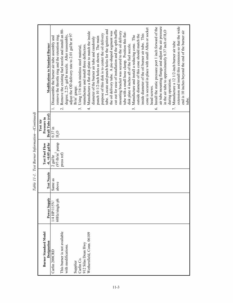
Car
lin
200C
RD
Thi
s bu
rner
is n
ot a
vail
able
wit
h m
odif
icat
ions
.
Sup
plie
rC
arli
n C
o.91
2 S
ilas
Dea
n H
wy
Wet
hers
fiel
d, C
onn.
061
09
1/4
HP
/115
V/
60H
z/si
ngle
ph
Sam
e as
abov
e2
gal/
hr(9
7-lb
/in2 p
ump
pres
s re
f)
0.37
inH
2O1.
Dis
asse
mbl
e th
e bu
rner
air
tube
ass
embl
y an
dre
mov
e th
e th
rott
le r
ing
and
the
rete
ntio
n ri
ng.
2. R
emov
e th
e ex
isti
ng f
uel n
ozzl
e an
d in
stal
l an
80-
degr
ee, 2
.25-
gal
/hr
nozz
le.
Aft
er r
eass
embl
y,ad
just
the
OD
del
iver
y ra
te to
2.0
1 ga
l/hr
at 9
7lb
/in2 g
auge
.3.
Usi
ng 1
/16
inch
sta
inle
ss s
teel
mat
eria
l,m
anuf
actu
re a
nd in
stal
l thr
ee d
efle
ctor
s.4.
Man
ufac
ture
a f
lat-
disk
pla
te to
mat
ch th
e in
side
diam
eter
of
the
burn
er a
ir tu
be a
nd r
ando
mly
punc
h 10
1/2
-inc
h ho
les
as s
how
n. T
he m
ain
purp
ose
of th
is d
isk
is to
cen
ter
the
oil d
eliv
ery
tube
. L
ocat
e an
d pu
nch
hole
s fo
r th
e ig
nito
rs a
ndth
e oi
l del
iver
y tu
be.
A p
ie-s
hape
d se
gmen
t was
cut o
ut f
or e
ase
of in
stal
lati
on a
nd th
e sp
lit-
baff
lem
ount
ing
brac
ket w
as s
ecur
ed to
the
oil d
eliv
ery
tube
wit
h a
smal
l hos
e cl
amp.
Pos
itio
n th
is f
lat-
disk
pla
te 4
inch
es a
ft o
f th
e fu
el n
ozzl
e.5.
Man
ufac
ture
and
inst
all a
red
ucin
g co
ne.
The
outs
ide
diam
eter
of
this
con
e sh
ould
mat
ch th
ein
side
dia
met
er o
f th
e oi
l bur
ner
air
tube
. T
his
cone
is s
ecur
ed in
pla
ce w
ith
smal
l All
en o
r so
cket
head
scr
ews.
6. I
nsta
ll th
e st
atic
pre
ssur
e po
rt 1
inch
for
war
d of
the
air
tube
mou
ntin
g fl
ange
and
adj
ust t
he a
ir p
ress
ure
in th
e ai
r tu
be to
app
roxi
mat
ely
0.37
inch
of
H2O
duri
ng o
pera
tion
.7.
Man
ufac
ture
a 1
2 1/
2-in
ch b
urne
r ai
r tu
beex
tens
ion
and
inst
all t
his
exte
nsio
n so
that
the
wid
een
d is
10
inch
es b
eyon
d th
e en
d of
the
burn
er a
irtu
be.

11-4
Tab
le 1
1-1.
Tes
t Bur
ner
Info
rmat
ion—
(Con
tinu
ed)
Bur
ner
Sta
ndar
d M
odel
Des
igna
tion
Pow
er S
uppl
yT
est
Noz
zle
Tes
t F
uel F
low
-0, +
0.05
gal
/hr
Tes
t A
irP
ress
ure
inD
raft
Tub
e (r
ef)
Mod
ific
atio
ns t
o S
tand
ard
Bur
ner
Par
k D
PL
340
0
Sup
plie
rP
ark
Man
ufac
turi
ng C
ompa
nyN
ew Y
ork
and
Abs
econ
Blv
d.A
tlan
tic
Cit
y, N
ew J
erse
y08
401
Thi
s bu
rner
wil
l be
buil
t to
the
FA
A’s
spe
cifi
cati
ons
upon
req
uest
.

11-5
heat input of 4,500 Btu/hr to the Btu heat transfer device described in section 11.3.3.2, or9.3 Btu/ft2-sec (10.6 W/cm2) as measured by a calorimeter described in section 11.3.3.1.
11.3.1.1 Burner Extension
A stainless steel funnel extension, fabricated in accordance with figure 11-1, will be used.The funnel will have an oblong exit 6 inches (152 mm) high by 11 inches (279 mm) wide.The funnel will be installed on the burner with the air tube shown in figure 11-2.
Figure 11-1. Burner Extension Funnel
Figure 11-2. Air Tube Reducing Cone
Material: 0.031-in inconelA = Burner extension tube OD

11-6
11.3.1.2 Burner Fuel
Society of Automotive Engineers (SAE) No. 2 diesel, kerosene, or equivalent will be usedfor burner fuel.
11.3.2 Thermocouples
A thermocouple rake containing at least five American National Standard Institute (ANSI) 22-gaugeChromel-Alumel (Type K) thermocouple sheathed in 1/16-inch (1.6-mm) -thick stainless steel orinconel tubes, or equivalent, will be provided. The thermocouples will be aligned in a row 1 ± 0.1 inch(25 ± 3 mm) apart.
11.3.3 Heat Flux Measuring Device
One of the following devices will be used to measure the heat flux density of the flame.
11.3.3.1 Calorimeter
A water-cooled calorimeter capable of measuring heat flux densities up to 15 Btu/ft2-sec
(17 W/cm2) may be provided for burner calibration. A Hy-Cal model 1300A total heat flux
density calorimeter available from Hy-Cal Engineering, Santa Fe Springs, California, orequivalent has been found suitable.
11.3.3.2 Btu Heat Transfer Device
Figures 11-4 to 11-10 show fabrication details of an acceptable copper tube device used tomeasure heat flux density. The mercury thermometers will be positioned in the mountingtubes so that the bottom of the bulb is within 1/16 inch (1.6 mm) of the bottom of thepassage in the heat transfer tube (see figures 11-7 and 11-8).
11.3.3.2.1 Thermometers
Two glass scientific thermometers calibrated in 0.05°C (0.1°F) increments,immersible thermocouples, or equivalent will be provided for the heat transfertube assembly.
11.3.4 Test Setup
A steel table measuring 60 inches (1,524 mm) wide, 28 inches (711 mm) deep, and 32 inches (813 mm)high has been found acceptable. The vibrating mechanism and hood, described below, may bemounted on this table. See figure 11-1 for an acceptable test setup.
Figure 11-3. Hose Assemblies Test Setup

11-7
Figure 11-4. Burner Calibration Standardization Apparatus
Figure 11-5. Btu Heat Transfer Device
Figure 11-6. Btu Heat Transfer Device—Reducer
Btu TransferDevice

11-8
Figure 11-7. Btu Heat Transfer Device—Inlet Tube
Figure 11-8. Btu Heat Transfer Device—Outlet Tube
Figure 11-9. Btu Heat Transfer Device—Thermometer Mounting

11-9
Figure 11-10. Btu Heat Transfer Device—Test Specimen
11.3.4.1 Vibration Source
A means will be provided to vibrate the hose assembly as shown in figure 11-8 at 33 Hz witha total displacement of a least 1/8 inch (3.2 mm), i.e., with an amplitude of at least 1/16 inch(1.6 mm).
11.3.4.2 Hood
A hood measuring 25 inches (635 mm) wide and 25 inches (635 mm) high has been foundacceptable. The hood may be placed on the bench near the vibration source so that thevibrating fitting for the hose attachment is located 7 inches (178 mm) behind the open frontof the hood.
11.3.4.2.1 Fan
The hood will have a fan installed on the rear to draw air through it at a velocityof 400 ft/min (203 cm/s), as measured by a velometer located at the positionoccupied by the hose assembly specimen during the test.
11.3.4.2.2 Photocell
The hood may contain a photocell to detect a flareup resulting from burning oildue to a hose failure.
11.3.4.3 Automatic Shutdown System
If a flareup of burning oil escaping from a failed hose assembly is detected, an automaticshutdown system may be provided to terminate the test by turning off the burner, vibratingmechanism, hood fan, and oil flow.
11.3.4.4 Temperature Measuring and Recording Equipment
A temperature sensing system will be provided that includes a sufficient number ofthermocouples to ensure that the specified temperature exists along the entire end fitting andalong the hose for a distance of not less than 5 inches (127 mm). The system will include arecorder to monitor the flame temperature throughout the fire test duration.
11.3.5 Oil Circulator and Heater
A device consisting of an oil tank with a temperature-controlled immersion heater and an electric oilpump will be provided if the hose assembly being tested must have oil pumped through the hose(s)during the test. The plumbing will include appropriate flow indicators, pressure gauges, control andselector valves, and pressure relief valves.

11-10
11.3.5.1 Oil
SAE No. 20 oil, in accordance with Military Specification MIL-L-2104C or equivalent, willbe provided and used in the oil circulator and heater to pump through the hose assembly testspecimen during the test.
11.4 Test Specimens
11.4.1 Prepare three specimens, 24 inches (610 mm) long, for the test.
11.4.2 The configuration of the hose test specimens will be as used in service. A firesleeve may be added tothe hose assembly, if needed, to enable the test specimens to withstand the fire test durationspecified.
11.5 Calibration
11.5.1 Place the thermocouple rake on the test stand at a distance 4 inches (102 mm) above the centerline ofthe burner extension. Connect the thermocouples to a stripchart recorder.
11.5.2 Light the burner, allow a 3-minute warmup, and move the burner into test position.
11.5.3 Begin monitoring the temperatures indicated by the thermocouples after 3 minutes. Makeadjustments as necessary to either the gas flow or the airflow to the burner in order to achieve aminimum average thermocouple reading of 2,000°F (1,100°C).
11.5.4 Turn the burner off, move it out of test position, and remove the thermocouple rake.
11.5.5 Replace the thermocouple rake with the heat flux measuring device. Follow section 11.5.5.1 if usinga water-cooled calorimeter for measuring heat flux. Follow section 11.5.5.2 if using a Btu heattransfer device for this purpose.
11.5.5.1 If using the water-cooled calorimeter described in section 11.3.3.1, place the calorimeter atthe same distance as the thermocouple rake centered over the burner exit.
11.5.5.1.1 Light the burner, allow a 2-minute warmup, and move the burner into testposition.
11.5.5.1.2 Measure the heat flux density continuously or at intervals no greater than 10seconds. If the heat flux density is not at least 9.3 Btu/ft2-sec (10.6 W/cm2),readjust the burner to achieve the proper heat flux. If burner adjustments arenecessary, remove the heat flux measuring device and repeat sections 11.5.1through 11.5.5.1.2.
11.5.5.2 If using the Btu heat transfer device described in section 11.3.3.2, ensure the externalsurface of the copper tubing on the Btu heat transfer device is clean prior to measuring heatflux. Use fine steel wool to clean the copper tubing. Inspect the tubing bore for corrosionand/or scale accumulation and remove before each test. A .45-caliber pistol cleaningbrush, or equivalent, with an extension has been found suitable for this purpose.
11.5.5.2.1 The calibration setup is shown in figure 11-3. Provide a 5-foot (1.5 m)constant head of water above the heat transfer device and a 2-foot (0.61 m)drop to the end of the tailpipe for adjustment of the water flow rate. Use a 1gallon (3.8 L) measuring container (a container and a weighing scale are alsoacceptable). Adjust the water flow rate to 500 lb/hr (227 kg/hr) or 1 gal/min(3.8 L/min). Supply water at a temperature of 50 to 70°F (10 to 21°C).
11.5.5.2.2 Start the water flowing through the Btu heat transfer device. Center the heattransfer tube in the flame at the same location that a hose assembly would beplaced for testing. Allow a 2-minute warmup period to stabilize flameconditions before temperature measurements from the mercury thermometersare recorded.

11-11
11.5.5.2.3 After the warmup period, record the inlet and outlet temperatures every 30seconds for a 3-minute period. Determine the rate of Btu increase of thewater as follows:
Heat transfer = 146 × (To - Ti) watts (for Celsius)
= 500 × (To - Ti) Btu/hr (for Fahrenheit)
where: To = temperature (°C or °F) at outlet
Ti = temperature (°C or °F) at inlet
11.5.5.2.4 The heat rate output, as determined by the equation shown in section11.5.5.2.3, will be a minimum of 4,500 Btu’s per hour. If the heat outputfrom the burner is not above this minimum, make adjustments to the burnerand repeat sections 11.5.1 through 11.5.5.2 until the burner is withintolerance.
11.6 Procedure
11.6.1 Specimen Mounting
Mount the hose assembly in the test setup to include at least one full 90-degree bend so that thepressure existing inside the hose will exert an axial force on the hose end fitting. Locate the hoseassembly 4 inches (102 mm) beyond the burner barrel extension so that the entire hose assembly endfitting and at least a minimum 5 inches (127 mm) of the hose is exposed to the flame. Install theentire hose assembly inside the hood unless limited by the physical characteristics of the hose such asminimum bend radius (see figure 11-1).
11.6.2 Preheat the oil in the oil tank to 200° ± 10°F (93° ± 6°C). Start the oil circulating pump and circulatethe oil through the test hose assembly at a flow rate and pressure as specified by hose type, size, andapplication. Pressures and flow rates are as shown in table 11-2.
Table 11-2. Circulating Oil Pressure and Flow Rate
Circulating Oil
Flow Rate
Hose Type Pressure GPM L/min
1a System Working 5 × ID (in)2
0.03 × ID (mm)2
1b System Working 1 × ID (in)2
0.006 × ID (mm)2
11a System Working 5 × ID (in)2
0.03 × ID (mm)2
11b System Working 1 × ID (in)2
0.006 × ID (mm)2
11.6.3 Start the vibrating mechanism and observe the movement of the hose. Ensure that no whipping ofthe hose occurs.
11.6.4 Start the hood air fan and begin monitoring the thermocouple recorder.
11.6.5 Start the burner. Periodically observe the recorded temperature to ensure that the required minimumflame temperature of 2,000°F (1,093°C) is maintained.
11.6.6 If a flareup of burning oil occurs due to a hose failure, terminate the test.
11.6.7 After the required test duration has been reached (i.e., 5 minutes for class A hose assemblies and15 minutes for class B hose assemblies), terminate the test.
11.6.7.1 Stop the burner.
11.6.7.2 Relieve the oil pressure in the hose assembly.
11.6.7.3 Turn off the temperature recorder.

11-12
11.7 Report
11.7.1 Fully identify the hose configuration, including the assembly and fittings, and the class for which it isbeing tested.
11.7.2 Report if there were any flareups of leaking oil and any other pertinent observations.
11.7.3 Report whether the hose configuration met the requirements of class A or class B assemblies.
11.8 Requirements
11.8.1 Class A Hose Assembly
A class A assembly will withstand the test procedure in section 6 for at least 5 minutes withoutleaking circulating oil.
11.8.2 Class B Hose Assembly
A class B hose assembly will withstand the test procedure described in section 6 for at least 5minutes without leaking circulating oil.

Chapter 11 Supplement 11-13
Chapter 11 Supplement
This supplement contains advisory material pertinent to referenced paragraphs.
11.2.6 A velometer manufactured by Alnor Instrument Company, 7555 North Linder Avenue, Skokie, Illinois60077-3822, catalog number 01518, has been found satisfactory.
11.3.3.2 A satisfactory version of the woven copper fabric shown in figure 11-5 is manufactured by Metal TextileCorporation, Roselle, New Jersey.
11.3.4.4 Permanent installation of temperature measuring thermocouples and continuous recorder has been addedfor better control of the flame temperature during calibration and test.
11.4.2 If a firesleeve is required to be added for a hose type to pass the test, a firesleeve must be fitted to that hosetype before it can be used in designated fire zones on an airplane.
11.6.2 Flow rate values given in table 11-2 were derived from the most recent TSO C53. Flow rates used for thetest will be minimum flow rates given for the actual installation, if known.