chapter 11 powerplant hose assemblies test
TRANSCRIPT
11-1
Chapter 11
Powerplant Hose Assemblies Test
11.1 Scope
11.1.1 This test method is used to determine the fire resistance of high-temperature hose assemblies used in
designated fire zones and to evaluate the damage due to flame and vibration for showing compliance
with TSO C42, C53A, and C75.
11.1.2 The requirements and procedures of this test method vary according to hose materials and hose
assembly application.
11.2 Definitions
11.2.1 Designated Fire Zone
A designated fire zone is defined as a region of the aircraft, such as engine and auxiliary power unit
compartments designated to require fire detection and extinguishing equipment, and as appropriate,
the use of materials that are fire resistant or fireproof.
11.2.2 Fireproof
Per FAR Part 1, (found in Subchapter ADefinitions, Part IDefinitions and Abbreviations) “in
designated fire zones means the ability of materials to withstand the heat from a severe fire of
extended duration at least as well as steel in dimensions appropriate for their purpose.”
Powerplant hose assemblies are demonstrated to be fireproof by meeting the requirements of this test
for a flame exposure time of 15 minutes.
11.2.3 Fire Resistant
Per FAR Part 1, (found in Subchapter ADefinitions, Part IDefinitions and Abbreviations) “with
respect to fluid carrying lines, fluid system parts, wiring, air ducts, fittings, and powerplant controls
means the capacity to perform the intended functions under the heat and other conditions likely to
occur when there is a fire at the place concerned.”
Powerplant hose assemblies are demonstrated to be fire resistant by meeting the requirements of this
test for a flame exposure time of 5 minutes.
11.2.4 Class A Hose Assembly
A class A hose assembly is defined as a hose assembly capable of withstanding exposure to this fire
test procedure for 5 minutes without failure (e.g., leaking circulating oil) per TSO C53a.
11.2.5 Class B Hose Assembly
A class B hose assembly is defined as a hose assembly capable of withstanding exposure to this fire
test procedure for 15 minutes without failure (e.g., leaking circulating oil) per TSO C53a.
11.2.6 Velometer
A device for measuring airflow velocity.
11.2.7 Photocell
An electronic device having output that varies in response to the intensity of incident visible light.
11.3 Apparatus
11.3.1 Test Burner
A modified gun-type conversion oil burner as described in table 11-1 will be used. The burner will
be calibrated to provide a minimum average flame temperature of 2,000°F (1,100°C) and a
minimum
11
-2
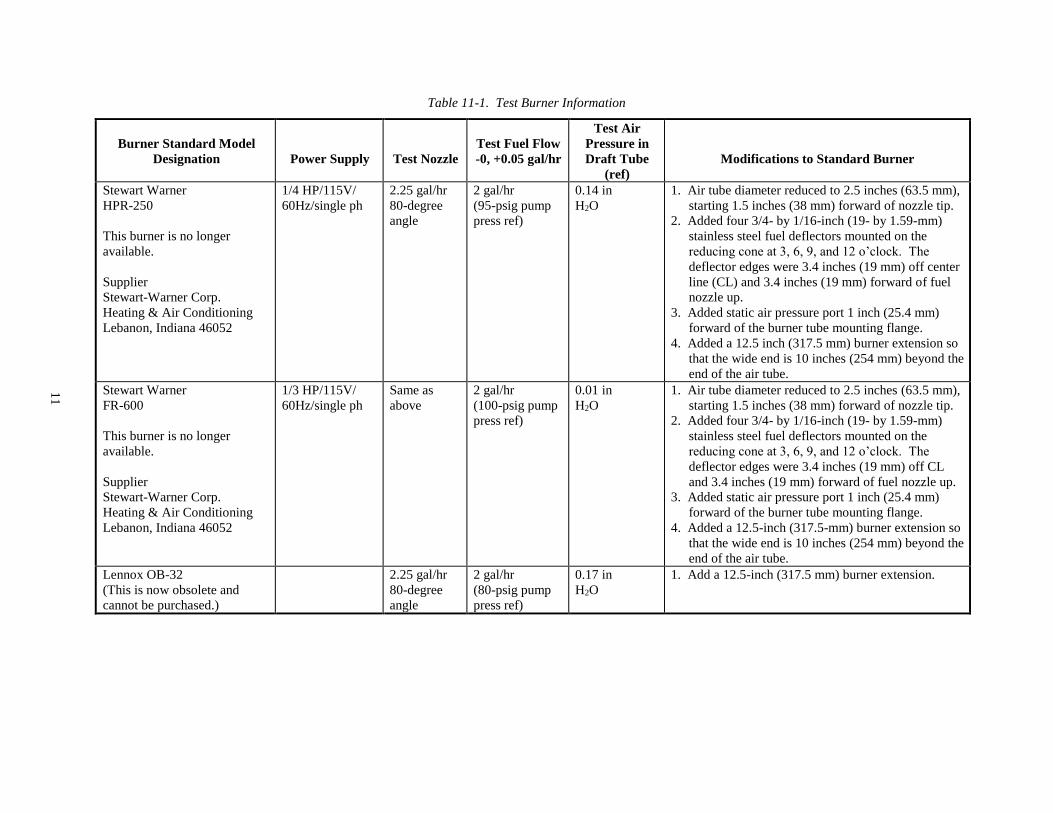
Table 11-1. Test Burner Information
Burner Standard Model
Designation
Power Supply
Test Nozzle
Test Fuel Flow
-0, +0.05 gal/hr
Test Air
Pressure in
Draft Tube
(ref)
Modifications to Standard Burner
Stewart Warner
HPR-250
This burner is no longer
available.
Supplier
Stewart-Warner Corp.
Heating & Air Conditioning
Lebanon, Indiana 46052
1/4 HP/115V/
60Hz/single ph
2.25 gal/hr
80-degree
angle
2 gal/hr
(95-psig pump
press ref)
0.14 in
H2O
1. Air tube diameter reduced to 2.5 inches (63.5 mm),
starting 1.5 inches (38 mm) forward of nozzle tip.
2. Added four 3/4- by 1/16-inch (19- by 1.59-mm)
stainless steel fuel deflectors mounted on the
reducing cone at 3, 6, 9, and 12 o’clock. The
deflector edges were 3.4 inches (19 mm) off center
line (CL) and 3.4 inches (19 mm) forward of fuel
nozzle up.
3. Added static air pressure port 1 inch (25.4 mm)
forward of the burner tube mounting flange.
4. Added a 12.5 inch (317.5 mm) burner extension so
that the wide end is 10 inches (254 mm) beyond the
end of the air tube.
Stewart Warner
FR-600
This burner is no longer
available.
Supplier
Stewart-Warner Corp.
Heating & Air Conditioning
Lebanon, Indiana 46052
1/3 HP/115V/
60Hz/single ph
Same as
above
2 gal/hr
(100-psig pump
press ref)
0.01 in
H2O
1. Air tube diameter reduced to 2.5 inches (63.5 mm),
starting 1.5 inches (38 mm) forward of nozzle tip.
2. Added four 3/4- by 1/16-inch (19- by 1.59-mm)
stainless steel fuel deflectors mounted on the
reducing cone at 3, 6, 9, and 12 o’clock. The
deflector edges were 3.4 inches (19 mm) off CL
and 3.4 inches (19 mm) forward of fuel nozzle up.
3. Added static air pressure port 1 inch (25.4 mm)
forward of the burner tube mounting flange.
4. Added a 12.5-inch (317.5-mm) burner extension so
that the wide end is 10 inches (254 mm) beyond the
end of the air tube.
Lennox OB-32
(This is now obsolete and
cannot be purchased.)
2.25 gal/hr
80-degree
angle
2 gal/hr
(80-psig pump
press ref)
0.17 in
H2O
1. Add a 12.5-inch (317.5 mm) burner extension.
11
-3
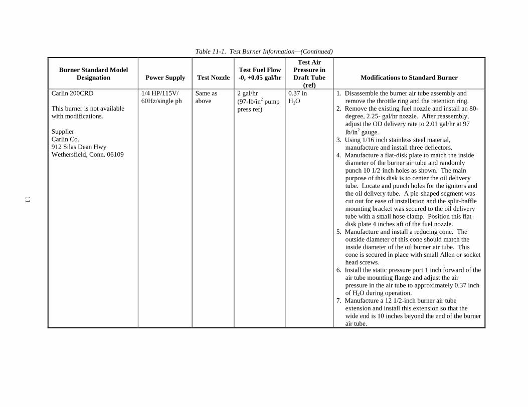
Table 11-1. Test Burner Information—(Continued)
Burner Standard Model
Designation
Power Supply
Test Nozzle
Test Fuel Flow
-0, +0.05 gal/hr
Test Air
Pressure in
Draft Tube
(ref)
Modifications to Standard Burner
Carlin 200CRD
This burner is not available
with modifications.
Supplier
Carlin Co.
912 Silas Dean Hwy
Wethersfield, Conn. 06109
1/4 HP/115V/
60Hz/single ph
Same as
above
2 gal/hr
(97-lb/in2 pump
press ref)
0.37 in
H2O
1. Disassemble the burner air tube assembly and
remove the throttle ring and the retention ring.
2. Remove the existing fuel nozzle and install an 80-
degree, 2.25- gal/hr nozzle. After reassembly,
adjust the OD delivery rate to 2.01 gal/hr at 97
lb/in2 gauge.
3. Using 1/16 inch stainless steel material,
manufacture and install three deflectors.
4. Manufacture a flat-disk plate to match the inside
diameter of the burner air tube and randomly
punch 10 1/2-inch holes as shown. The main
purpose of this disk is to center the oil delivery
tube. Locate and punch holes for the ignitors and
the oil delivery tube. A pie-shaped segment was
cut out for ease of installation and the split-baffle
mounting bracket was secured to the oil delivery
tube with a small hose clamp. Position this flat-
disk plate 4 inches aft of the fuel nozzle.
5. Manufacture and install a reducing cone. The
outside diameter of this cone should match the
inside diameter of the oil burner air tube. This
cone is secured in place with small Allen or socket
head screws.
6. Install the static pressure port 1 inch forward of the
air tube mounting flange and adjust the air
pressure in the air tube to approximately 0.37 inch
of H2O during operation.
7. Manufacture a 12 1/2-inch burner air tube
extension and install this extension so that the
wide end is 10 inches beyond the end of the burner
air tube.
11
-4
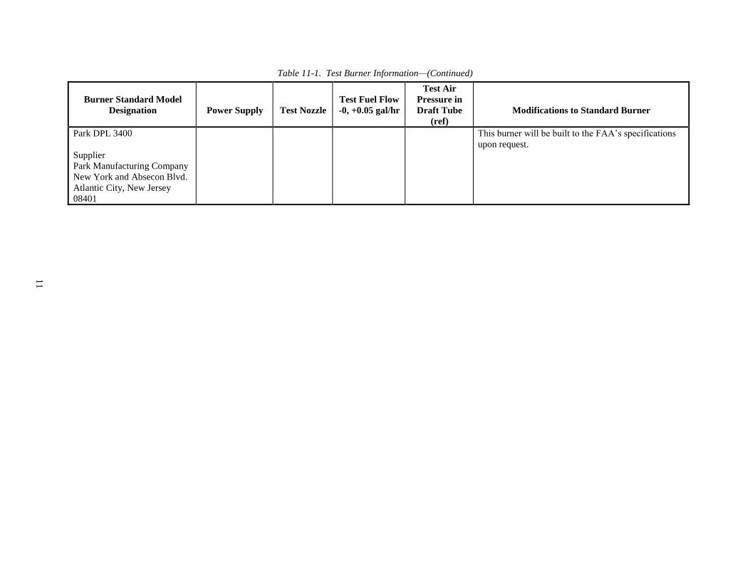
Table 11-1. Test Burner Information—(Continued)
Burner Standard Model
Designation
Power Supply
Test Nozzle
Test Fuel Flow
-0, +0.05 gal/hr
Test Air
Pressure in
Draft Tube
(ref)
Modifications to Standard Burner
Park DPL 3400
Supplier
Park Manufacturing Company
New York and Absecon Blvd.
Atlantic City, New Jersey
08401
This burner will be built to the FAA’s specifications
upon request.
11-5
heat input of 4,500 Btu/hr to the Btu heat transfer device described in section 11.3.3.2, or
9.3 Btu/ft2-sec (10.6 W/cm2) as measured by a calorimeter described in section 11.3.3.1.
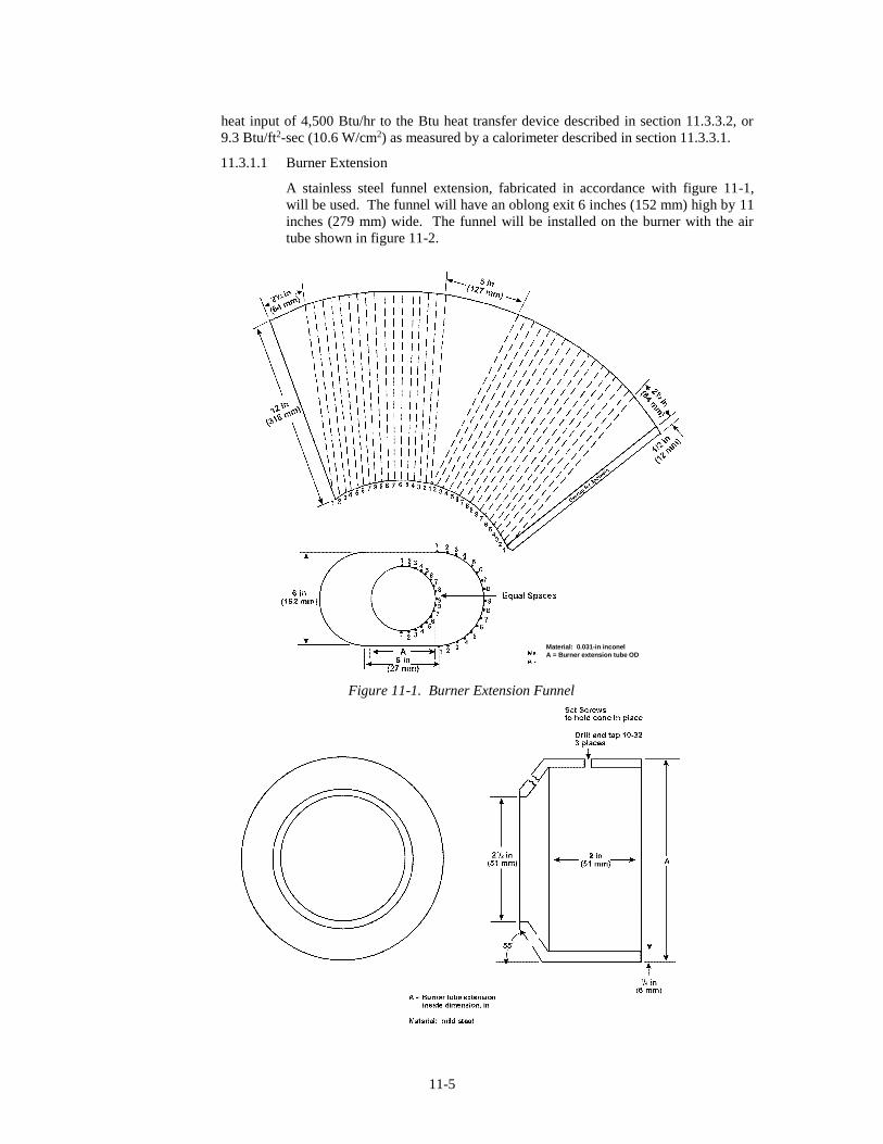
11.3.1.1 Burner Extension
A stainless steel funnel extension, fabricated in accordance with figure 11-1,
will be used. The funnel will have an oblong exit 6 inches (152 mm) high by 11
inches (279 mm) wide. The funnel will be installed on the burner with the air
tube shown in figure 11-2.
Figure 11-1. Burner Extension Funnel
Material: 0.031-in inconel
A = Burner extension tube OD
11-6
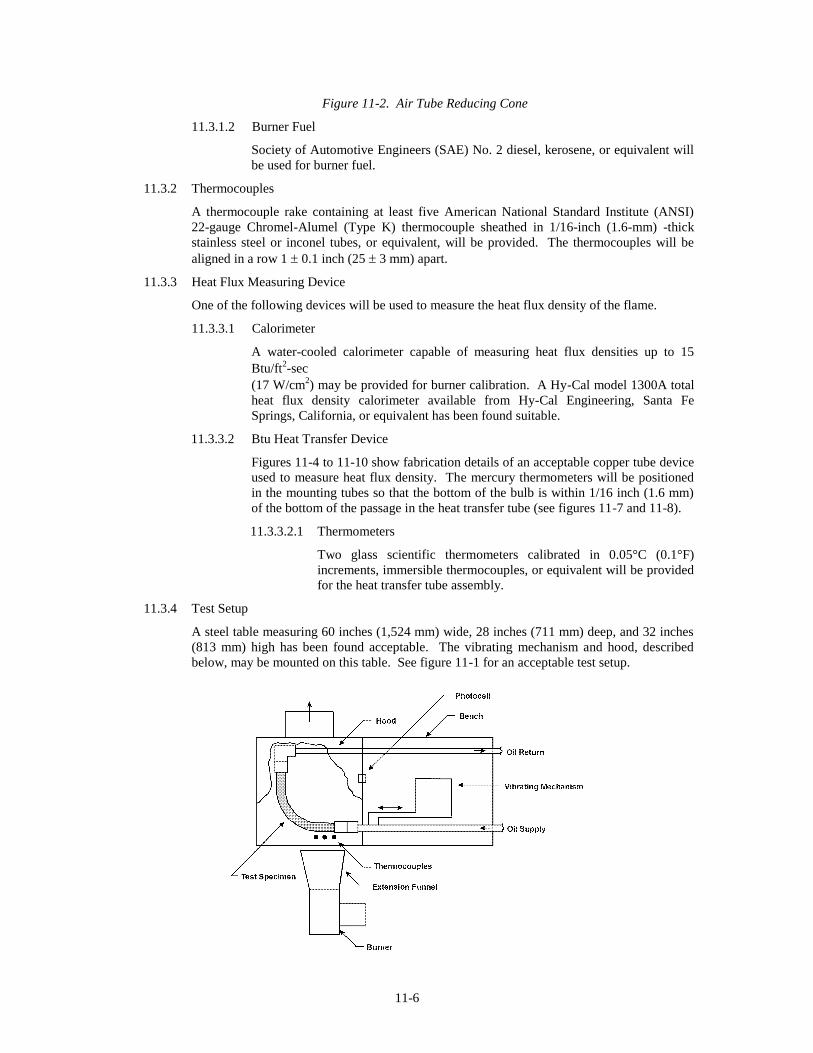
Figure 11-2. Air Tube Reducing Cone
11.3.1.2 Burner Fuel
Society of Automotive Engineers (SAE) No. 2 diesel, kerosene, or equivalent will
be used for burner fuel.
11.3.2 Thermocouples
A thermocouple rake containing at least five American National Standard Institute (ANSI)
22-gauge Chromel-Alumel (Type K) thermocouple sheathed in 1/16-inch (1.6-mm) -thick
stainless steel or inconel tubes, or equivalent, will be provided. The thermocouples will be
aligned in a row 1 0.1 inch (25 3 mm) apart.
11.3.3 Heat Flux Measuring Device
One of the following devices will be used to measure the heat flux density of the flame.
11.3.3.1 Calorimeter
A water-cooled calorimeter capable of measuring heat flux densities up to 15
Btu/ft2-sec
(17 W/cm2) may be provided for burner calibration. A Hy-Cal model 1300A total
heat flux density calorimeter available from Hy-Cal Engineering, Santa Fe
Springs, California, or equivalent has been found suitable.
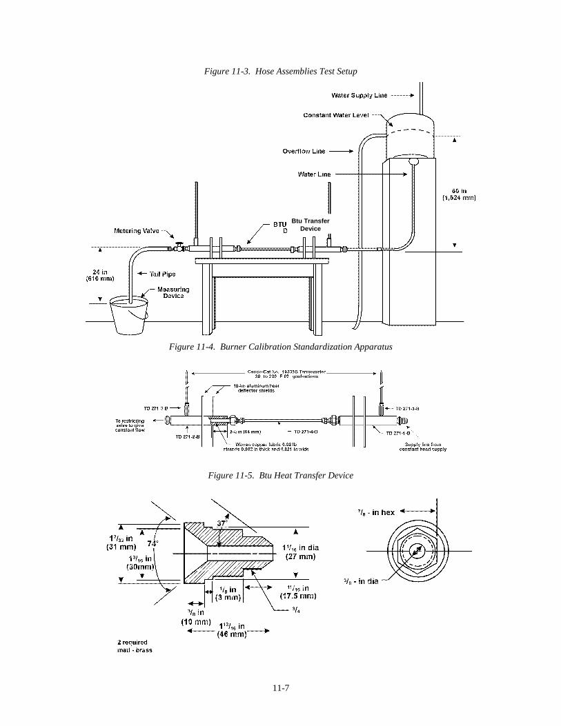
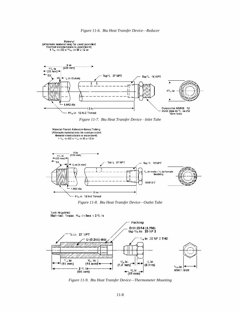
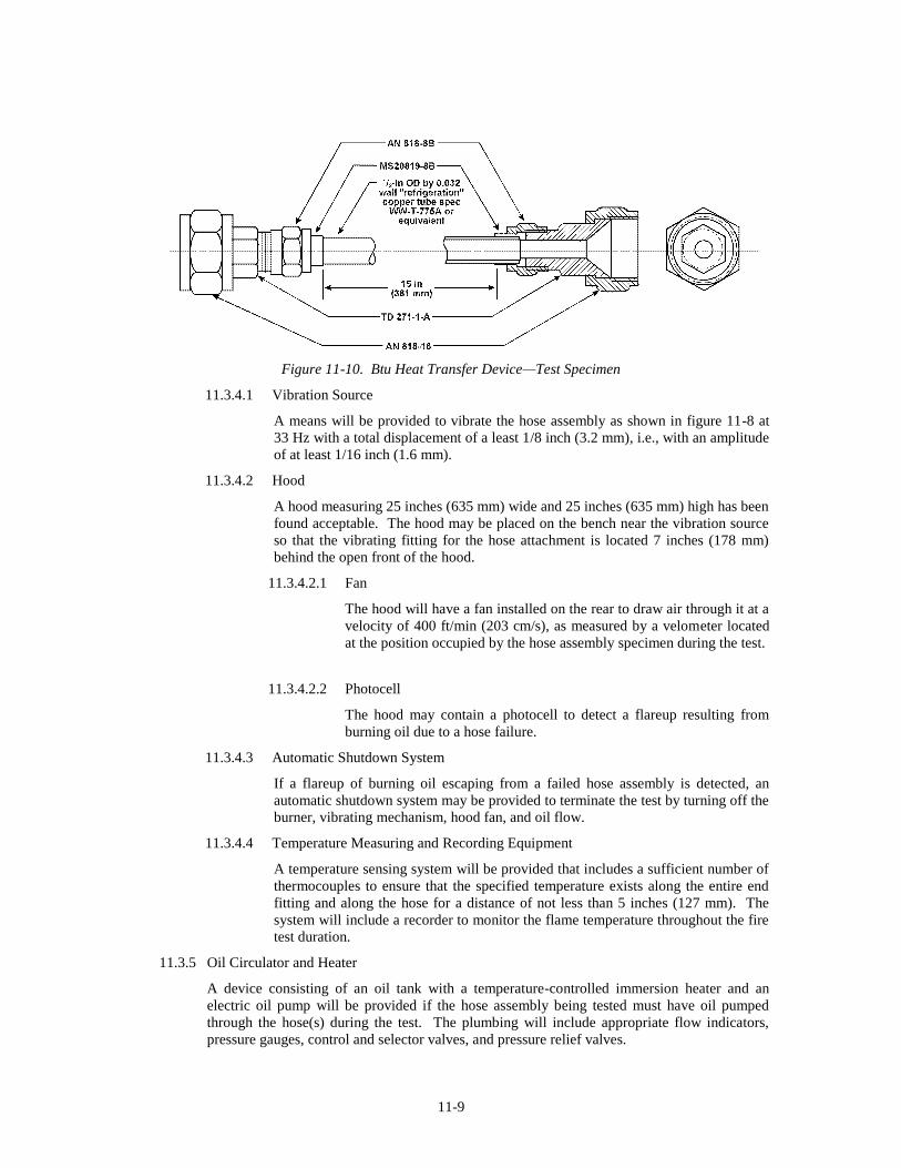
11.3.3.2 Btu Heat Transfer Device
Figures 11-4 to 11-10 show fabrication details of an acceptable copper tube device
used to measure heat flux density. The mercury thermometers will be positioned
in the mounting tubes so that the bottom of the bulb is within 1/16 inch (1.6 mm)
of the bottom of the passage in the heat transfer tube (see figures 11-7 and 11-8).
11.3.3.2.1 Thermometers
Two glass scientific thermometers calibrated in 0.05°C (0.1°F)
increments, immersible thermocouples, or equivalent will be provided
for the heat transfer tube assembly.
11.3.4 Test Setup
A steel table measuring 60 inches (1,524 mm) wide, 28 inches (711 mm) deep, and 32 inches
(813 mm) high has been found acceptable. The vibrating mechanism and hood, described
below, may be mounted on this table. See figure 11-1 for an acceptable test setup.
11-7
Figure 11-3. Hose Assemblies Test Setup
Figure 11-4. Burner Calibration Standardization Apparatus
Figure 11-5. Btu Heat Transfer Device
Btu Transfer
Device
11-8
Figure 11-6. Btu Heat Transfer Device—Reducer
Figure 11-7. Btu Heat Transfer Device—Inlet Tube
Figure 11-8. Btu Heat Transfer Device—Outlet Tube
Figure 11-9. Btu Heat Transfer Device—Thermometer Mounting
11-9
Figure 11-10. Btu Heat Transfer Device—Test Specimen
11.3.4.1 Vibration Source
A means will be provided to vibrate the hose assembly as shown in figure 11-8 at
33 Hz with a total displacement of a least 1/8 inch (3.2 mm), i.e., with an amplitude
of at least 1/16 inch (1.6 mm).
11.3.4.2 Hood
A hood measuring 25 inches (635 mm) wide and 25 inches (635 mm) high has been
found acceptable. The hood may be placed on the bench near the vibration source
so that the vibrating fitting for the hose attachment is located 7 inches (178 mm)
behind the open front of the hood.
11.3.4.2.1 Fan
The hood will have a fan installed on the rear to draw air through it at a
velocity of 400 ft/min (203 cm/s), as measured by a velometer located
at the position occupied by the hose assembly specimen during the test.
11.3.4.2.2 Photocell
The hood may contain a photocell to detect a flareup resulting from
burning oil due to a hose failure.
11.3.4.3 Automatic Shutdown System
If a flareup of burning oil escaping from a failed hose assembly is detected, an
automatic shutdown system may be provided to terminate the test by turning off the
burner, vibrating mechanism, hood fan, and oil flow.
11.3.4.4 Temperature Measuring and Recording Equipment
A temperature sensing system will be provided that includes a sufficient number of
thermocouples to ensure that the specified temperature exists along the entire end
fitting and along the hose for a distance of not less than 5 inches (127 mm). The
system will include a recorder to monitor the flame temperature throughout the fire
test duration.
11.3.5 Oil Circulator and Heater
A device consisting of an oil tank with a temperature-controlled immersion heater and an
electric oil pump will be provided if the hose assembly being tested must have oil pumped
through the hose(s) during the test. The plumbing will include appropriate flow indicators,
pressure gauges, control and selector valves, and pressure relief valves.
11-10
11.3.5.1 Oil
SAE No. 20 oil, in accordance with Military Specification MIL-L-2104C or
equivalent, will be provided and used in the oil circulator and heater to pump
through the hose assembly test specimen during the test.
11.4 Test Specimens
11.4.1 Prepare three specimens, 24 inches (610 mm) long, for the test.
11.4.2 The configuration of the hose test specimens will be as used in service. A firesleeve may
be added to the hose assembly, if needed, to enable the test specimens to withstand the fire
test duration specified.
11.5 Calibration
11.5.1 Place the thermocouple rake on the test stand at a distance 4 inches (102 mm) above the
centerline of the burner extension. Connect the thermocouples to a stripchart recorder.
11.5.2 Light the burner, allow a 3-minute warmup, and move the burner into test position.
11.5.3 Begin monitoring the temperatures indicated by the thermocouples after 3 minutes. Make
adjustments as necessary to either the gas flow or the airflow to the burner in order to
achieve a minimum average thermocouple reading of 2,000°F (1,100°C).
11.5.4 Turn the burner off, move it out of test position, and remove the thermocouple rake.
11.5.5 Replace the thermocouple rake with the heat flux measuring device. Follow section
11.5.5.1 if using a water-cooled calorimeter for measuring heat flux. Follow section
11.5.5.2 if using a Btu heat transfer device for this purpose.
11.5.5.1 If using the water-cooled calorimeter described in section 11.3.3.1, place the
calorimeter at the same distance as the thermocouple rake centered over the
burner exit.
11.5.5.1.1 Light the burner, allow a 2-minute warmup, and move the burner
into test position.
11.5.5.1.2 Measure the heat flux density continuously or at intervals no greater
than 10 seconds. If the heat flux density is not at least 9.3 Btu/ft2-
sec (10.6 W/cm2), readjust the burner to achieve the proper heat
flux. If burner adjustments are necessary, remove the heat flux
measuring device and repeat sections 11.5.1 through 11.5.5.1.2.
11.5.5.2 If using the Btu heat transfer device described in section 11.3.3.2, ensure the
external surface of the copper tubing on the Btu heat transfer device is clean prior
to measuring heat flux. Use fine steel wool to clean the copper tubing. Inspect
the tubing bore for corrosion and/or scale accumulation and remove before each
test. A .45-caliber pistol cleaning brush, or equivalent, with an extension has
been found suitable for this purpose.
11.5.5.2.1 The calibration setup is shown in figure 11-3. Provide a 5-foot (1.5
m) constant head of water above the heat transfer device and a 2-
foot (0.61 m) drop to the end of the tailpipe for adjustment of the
water flow rate. Use a 1 gallon (3.8 L) measuring container (a
container and a weighing scale are also acceptable). Adjust the
water flow rate to 500 lb/hr (227 kg/hr) or 1 gal/min (3.8 L/min).
Supply water at a temperature of 50 to 70°F (10 to 21°C).
11.5.5.2.2 Start the water flowing through the Btu heat transfer device. Center
the heat transfer tube in the flame at the same location that a hose
assembly would be placed for testing. Allow a 2-minute warmup
11-11
period to stabilize flame conditions before temperature
measurements from the mercury thermometers are recorded.
11.5.5.2.3 After the warmup period, record the inlet and outlet temperatures
every 30 seconds for a 3-minute period. Determine the rate of Btu
increase of the water as follows:
Heat transfer = 146 (To - Ti) watts (for Celsius)
= 500 (To - Ti) Btu/hr (for Fahrenheit)
where: To = temperature (C or F) at outlet
Ti = temperature (C or F) at inlet
11.5.5.2.4 The heat rate output, as determined by the equation shown in
section 11.5.5.2.3, will be a minimum of 4,500 Btu’s per hour. If
the heat output from the burner is not above this minimum, make
adjustments to the burner and repeat sections 11.5.1 through
11.5.5.2 until the burner is within tolerance.
11.6 Procedure
11.6.1 Specimen Mounting
Mount the hose assembly in the test setup to include at least one full 90-degree bend so that
the pressure existing inside the hose will exert an axial force on the hose end fitting. Locate
the hose assembly 4 inches (102 mm) beyond the burner barrel extension so that the entire
hose assembly end fitting and at least a minimum 5 inches (127 mm) of the hose is exposed
to the flame. Install the entire hose assembly inside the hood unless limited by the physical
characteristics of the hose such as minimum bend radius (see figure 11-1).
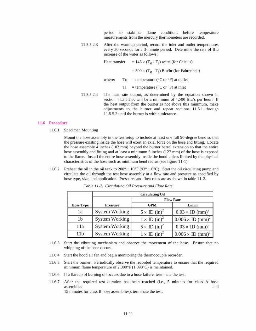
11.6.2 Preheat the oil in the oil tank to 200° 10°F (93° 6°C). Start the oil circulating pump and
circulate the oil through the test hose assembly at a flow rate and pressure as specified by
hose type, size, and application. Pressures and flow rates are as shown in table 11-2.
Table 11-2. Circulating Oil Pressure and Flow Rate
Circulating Oil
Flow Rate
Hose Type Pressure GPM L/min
1a System Working 5 ID (in)2 0.03 ID (mm)
2
1b System Working 1 ID (in)2 0.006 ID (mm)
2
11a System Working 5 ID (in)2 0.03 ID (mm)
2
11b System Working 1 ID (in)2 0.006 ID (mm)
2
11.6.3 Start the vibrating mechanism and observe the movement of the hose. Ensure that no
whipping of the hose occurs.
11.6.4 Start the hood air fan and begin monitoring the thermocouple recorder.
11.6.5 Start the burner. Periodically observe the recorded temperature to ensure that the required
minimum flame temperature of 2,000°F (1,093°C) is maintained.
11.6.6 If a flareup of burning oil occurs due to a hose failure, terminate the test.
11.6.7 After the required test duration has been reached (i.e., 5 minutes for class A hose
assemblies and
15 minutes for class B hose assemblies), terminate the test.
11-12
11.6.7.1 Stop the burner.
11.6.7.2 Relieve the oil pressure in the hose assembly.
11.6.7.3 Turn off the temperature recorder.
11.7 Report
11.7.1 Fully identify the hose configuration, including the assembly and fittings, and the class for
which it is being tested.
11.7.2 Report if there were any flareups of leaking oil and any other pertinent observations.
11.7.3 Report whether the hose configuration met the requirements of class A or class B
assemblies.
11.8 Requirements
11.8.1 Class A Hose Assembly
A class A assembly will withstand the test procedure in section 6 for at least 5 minutes
without leaking circulating oil.
11.8.2 Class B Hose Assembly
A class B hose assembly will withstand the test procedure described in section 6 for at least
15 minutes without leaking circulating oil.
11-13
Chapter 11 Supplement
This supplement contains advisory material pertinent to referenced paragraphs.
11.2.6 A velometer manufactured by Alnor Instrument Company, 7555 North Linder Avenue, Skokie,
Illinois 60077-3822, catalog number 01518, has been found satisfactory.
11.3.3.2 A satisfactory version of the woven copper fabric shown in figure 11-5 is manufactured by
Metal Textile Corporation, Roselle, New Jersey.
11.3.4.4 Permanent installation of temperature measuring thermocouples and continuous recorder has
been added for better control of the flame temperature during calibration and test.
11.4.2 If a firesleeve is required to be added for a hose type to pass the test, a firesleeve must be fitted to
that hose type before it can be used in designated fire zones on an airplane.
11.6.2 Flow rate values given in table 11-2 were derived from the most recent TSO C53. Flow rates used
for the test will be minimum flow rates given for the actual installation, if known.