feasibility study final report - gaslight...
TRANSCRIPT

DILWORTH HOTEL
Boyne City, Michigan
FEASIBILITY STUDY FINAL REPORT
30 June 2010
Prepared for: City of Boyne City
21000029


Architectural Study Report Wolverine Dilworth Hotel
Quinn Evans Architects 1 30 June 2010
INTRODUCTION DESCRIPTION
The Wolverine Dilworth Hotel is located at 300 Water Street in downtown Boyne City, Michigan. It was constructed in 1912 as a hotel with a restaurant and bar. It underwent major renovation in 1984. At that time the public spaces were restored and the guestrooms were reconfigured to create 27 unique guestrooms and suites. It continued to operate as a hotel and gathering space until 2008 when it closed. This study was commissioned by the Boyne City Mainstreet Program to determine the potential for rehabilitating the building and reopening it. The study evaluates the condition of the building and the building systems to determine the extent of rehabilitation necessary to return the building to use. It also evaluates the economic potential for returning the building to use as a hotel, restaurant/bar and banquet facility. This report summarizes the findings of the building condition survey. A separate (attached) report contains the findings of the economic feasibility study. If the project uses historic preservation tax credits as a component of its funding, the design and construction must meet the Secretary of the Interior’s Standards for Rehabilitation. These Standards require that both the historic character and historic fabric of the building be retained. The recommendations for repair and improvements presented below are intended to meet these Standards. The hotel is a three story, Classical Revival building with load-bearing masonry walls and wood frame construction. It also has a full basement. A covered porch runs the full length of the north elevation, and the north half of the east and west elevations. A decorative cornice is intact at the west and south elevations, but missing from the east and north elevations. The first floor contains the majority of the gathering spaces for the hotel, banquet room, and restaurant guests. Upon entry through the vestibules, the lobby contains the hotel front desk and informal gathering space around a fireplace. From the lobby, guests have access to the banquet room, restaurant, grand staircase, and an elevator to the upstairs guest rooms or downstairs bar. The second and third floors contain the guest rooms and support spaces. Upon arrival at each floor, a small informal gathering space is provided for guests to socialize with each other. Each guest room is equipped with its own attached bathroom.

Architectural Study Report Wolverine Dilworth Hotel
Quinn Evans Architects 2 30 June 2010
Over half of the basement is unfinished and houses mechanical equipment and support services for the hotel such as laundry and maintenance. The remainder of the basement contains a bar and supporting restrooms.
BUILDING CODES Michigan is currently working under the 2006 Michigan Building Code and the 2006 Michigan Rehabilitation Code. It is anticipated the State of Michigan will adopt the 2009 versions by the end of 2010. Given the schedule for this project, it is expected that the project will fall under the requirements of the 2009 codes.
The project can be designed under the provisions of the Michigan Building Code or the Michigan Rehabilitation Code. The Rehabilitation Code provides code compliance options that are sometimes more compatible with the existing conditions in historic buildings. This study will point out where the Rehabilitation Code might provide desired flexibility over the Building Code.
LIFE SAFETY
Although the building has been operated as hotel, restaurant and banquet facility for many years, it does not meet all current code requirements. The following paragraphs are a general code review. They describe specific code requirements and identify deficiencies that should be addressed in any major rehabilitation of the building. Construction Type and Size The building is Type III construction. It falls within the permitted size and height for hotel use. The assembly spaces at the first floor and basement are also permitted within this construction type. Fire Resistance Rated Construction It appears that when the building was renovated in 1984, the corridor walls and ceilings were clad in 5/8” drywall giving them the required one hour fire resistance rating. The inspection was not able to determine if openings where building systems penetrate the floor/ceiling construction are protected as required by code. As these systems are repaired and replaced any penetrations must be protected. The guestroom doors off the corridors are historic five panel doors with transom panels. They are character defining features of the building, but they are not fire rated. In addition, the doors are not automatic closing as required. The Rehabilitation Code provides some flexibility for retention of historic doors and transoms. Under the building code, the doors and transoms may be retained if the building can meet the alternative code compliance standards outlined in Chapter 34. Under the historic Rehabilitation Standards

Architectural Study Report Wolverine Dilworth Hotel
Quinn Evans Architects 3 30 June 2010
for the tax credits, if the doors cannot be retained, they must be replaced with new doors that match the character of the original doors. The stairs must be enclosed in fire-resistant rated construction. None of the stairs meet this requirement. The east stair could be enclosed by closing off the end of the corridor. This would capture the door to four guest rooms in the stair enclosure. The Building Code would not permit these doors in the stairway, but the Rehabilitation Code would. The grand stair in the middle of the building is open to the basement, first, second and third floors. This is not permitted by the Building Code. In fully sprinkled buildings, the Rehabilitation Code permits stairs to be open to three floors, but not four. Therefore, the stair will need to be separated from at least one floor. Under the provisions for historic buildings in the Building Code the use of water curtains and other special safety features may permit the retention of the open stair between more than two floors. Fire Protection Systems The building currently has a fire suppression riser. It does not have a fire suppression system throughout. Installation of a fire suppression system would be required by the Michigan Building Code and would be necessary under the Rehabilitation Code to take advantage of other provisions of that code. The building does not have a fire alarm system. One is required by both the Building and Rehabilitation Codes. Means of Egress The building is required to have two means of egress from each floor. It does not. The construction of a new stair at the south end of the west wing would provide a necessary exit from that wing at each floor. Both the Building Code and the Rehab Code permit the construction of either an unenclosed or an enclosed stair in this location. Enclosure of the existing stair near the south end is discussed above. Under the Building Code this exit cannot continue to exit through the first floor. It can under the Rehabilitation Code. Neither of the exits from the basement bar meets code requirements. Construction of a new stair tower at the south end of the west wing would provide one means. Improvement of the grand stair could provide the second means. Exits signs and emergency lighting are required throughout the egress paths including corridors, stairways, and public areas at the first floor. The existing signs and emergency lights do not

Architectural Study Report Wolverine Dilworth Hotel
Quinn Evans Architects 4 30 June 2010
EXTERIOR ROOF
FIGURE 1: Roof termination at parapet cap
FIGURE 2: Roof at north-east corner
appear to meet current standards. Accessibility Access to the building is provided by a ramp from the exterior and an elevator at the interior. The restroom and bathrooms do not meet current accessibility standards. None of the hardware meets accessibility requirements. The roof over the main building is an EPDM membrane. The membrane may have been replaced since the 1980s renovation. However, the membrane has reached the end of its useful life. The membrane shows signs of cracking and ripples have formed in certain areas. Additionally, there are areas where mastic has been used to mend cracks in the membrane, or splice seams together at the location of previous repairs. One severe condition with the existing roof is the lack of proper membrane termination. The membrane is lapped over parapet cap stones and held in place with mastic (Figure 1). The mastic is dried and cracked. The edge of the membrane is loose allowing moisture to penetrate under the membrane. The height of the parapet is rather shallow, making it difficult to terminate the membrane using recommended details. QEA recommends that through wall flashing be installed below the cap stone to accommodate recommended roofing edge details while protecting the masonry from water penetration from the parapet. The historic standards will most likely not permit the installation of metal cap flashing over the historic stone cap flashing. Similarly, the membrane was not terminated properly at the chimney allowing those joints to open over time. The current roof structure has a substantial slope to channel the water to the roof drains (Figure 2). However, the current drainage system appears to be inadequate to handle the amount of rainwater generated on the roof. Two (2) approximately 3” roof drains are provided without overflow drainage. Installation of larger, and potentially more roof drains with overflows is recommended. They will be required under the Building Code, but not the Rehabilitation Code.
Architectural Study Report Wolverine Dilworth Hotel
Quinn Evans Architects 5 30 June 2010
PORCH ROOF
FIGURE 3: North Porch Roof
FIGURE 4: Porch roof flashing and gutter
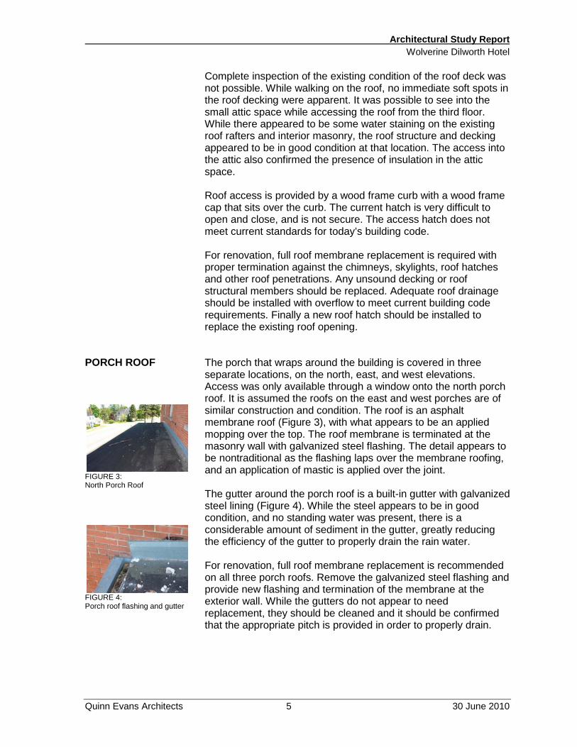
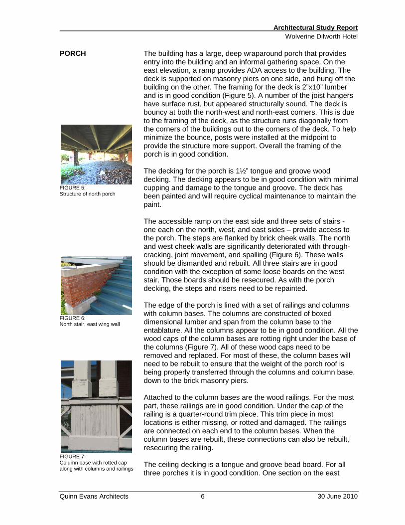
Complete inspection of the existing condition of the roof deck was not possible. While walking on the roof, no immediate soft spots in the roof decking were apparent. It was possible to see into the small attic space while accessing the roof from the third floor. While there appeared to be some water staining on the existing roof rafters and interior masonry, the roof structure and decking appeared to be in good condition at that location. The access into the attic also confirmed the presence of insulation in the attic space. Roof access is provided by a wood frame curb with a wood frame cap that sits over the curb. The current hatch is very difficult to open and close, and is not secure. The access hatch does not meet current standards for today’s building code. For renovation, full roof membrane replacement is required with proper termination against the chimneys, skylights, roof hatches and other roof penetrations. Any unsound decking or roof structural members should be replaced. Adequate roof drainage should be installed with overflow to meet current building code requirements. Finally a new roof hatch should be installed to replace the existing roof opening. The porch that wraps around the building is covered in three separate locations, on the north, east, and west elevations. Access was only available through a window onto the north porch roof. It is assumed the roofs on the east and west porches are of similar construction and condition. The roof is an asphalt membrane roof (Figure 3), with what appears to be an applied mopping over the top. The roof membrane is terminated at the masonry wall with galvanized steel flashing. The detail appears to be nontraditional as the flashing laps over the membrane roofing, and an application of mastic is applied over the joint. The gutter around the porch roof is a built-in gutter with galvanized steel lining (Figure 4). While the steel appears to be in good condition, and no standing water was present, there is a considerable amount of sediment in the gutter, greatly reducing the efficiency of the gutter to properly drain the rain water. For renovation, full roof membrane replacement is recommended on all three porch roofs. Remove the galvanized steel flashing and provide new flashing and termination of the membrane at the exterior wall. While the gutters do not appear to need replacement, they should be cleaned and it should be confirmed that the appropriate pitch is provided in order to properly drain.
Architectural Study Report Wolverine Dilworth Hotel
Quinn Evans Architects 6 30 June 2010
PORCH
FIGURE 5: Structure of north porch
FIGURE 6: North stair, east wing wall
FIGURE 7: Column base with rotted cap along with columns and railings
The building has a large, deep wraparound porch that provides entry into the building and an informal gathering space. On the east elevation, a ramp provides ADA access to the building. The deck is supported on masonry piers on one side, and hung off the building on the other. The framing for the deck is 2”x10” lumber and is in good condition (Figure 5). A number of the joist hangers have surface rust, but appeared structurally sound. The deck is bouncy at both the north-west and north-east corners. This is due to the framing of the deck, as the structure runs diagonally from the corners of the buildings out to the corners of the deck. To help minimize the bounce, posts were installed at the midpoint to provide the structure more support. Overall the framing of the porch is in good condition. The decking for the porch is 1½” tongue and groove wood decking. The decking appears to be in good condition with minimal cupping and damage to the tongue and groove. The deck has been painted and will require cyclical maintenance to maintain the paint. The accessible ramp on the east side and three sets of stairs - one each on the north, west, and east sides – provide access to the porch. The steps are flanked by brick cheek walls. The north and west cheek walls are significantly deteriorated with through-cracking, joint movement, and spalling (Figure 6). These walls should be dismantled and rebuilt. All three stairs are in good condition with the exception of some loose boards on the west stair. Those boards should be resecured. As with the porch decking, the steps and risers need to be repainted. The edge of the porch is lined with a set of railings and columns with column bases. The columns are constructed of boxed dimensional lumber and span from the column base to the entablature. All the columns appear to be in good condition. All the wood caps of the column bases are rotting right under the base of the columns (Figure 7). All of these wood caps need to be removed and replaced. For most of these, the column bases will need to be rebuilt to ensure that the weight of the porch roof is being properly transferred through the columns and column base, down to the brick masonry piers. Attached to the column bases are the wood railings. For the most part, these railings are in good condition. Under the cap of the railing is a quarter-round trim piece. This trim piece in most locations is either missing, or rotted and damaged. The railings are connected on each end to the column bases. When the column bases are rebuilt, these connections can also be rebuilt, resecuring the railing. The ceiling decking is a tongue and groove bead board. For all three porches it is in good condition. One section on the east

Architectural Study Report Wolverine Dilworth Hotel
Quinn Evans Architects 7 30 June 2010
CORNICE
FIGURE 8: Cornice at northwest corner MASONRY
FIGURE 9: Masonry at top of building
porch is sagging and needs to be reattached. This sagging may be caused by water leaking into the porch from the roof above, causing rotting of the ceiling. However, currently there is no indication of water damage and rot. The wood entablature and cornice is in good condition. There are a few areas on all three porches where the crown molding is damaged or coming loose and should be replaced with a matching profile. The building originally had a cornice that wrapped around all four elevations. Currently the cornice is only on the south and west elevations. The cornice has been removed from the north and east elevations. The wood outriggers were cut. Some remain in place in their masonry pockets. Some were removed leaving the masonry pockets empty. In either case, the exposed brick and mortar that was originally behind the cornice has begun to fail causing bricks to shift and or fall from the face of the building. The end of the cornice has been left exposed, allowing for an attractive nesting spot for birds (Figure 8). The cornice at the north and east elevations should be rebuilt to match the profile of the remaining original cornice. Masonry work should be performed to ensure the new outriggers that support the cornice are secure. The remaining original cornice does not appear to need rebuilding; however, the end sections that have been exposed to the elements should be removed and rebuilt. The roof of the cornice appears to be metal, and should be replaced in its entirety along with proper flashing back into the masonry wall. The entire cornice should be fully repainted. The building has solid load-bearing exterior brick walls. They are in generally good condition with specific areas of deterioration where moisture appears to be eroding the face of the brick. The Rehabilitation Standards require that historic masonry be repaired using brick and mortar that matches the original. The majority of the masonry damage occurs above the third story windows (Figure 9). As noted above, the parapet caps should be removed and reinstalled, so that through-wall flashing can be installed under them to prevent continued moisture penetration into the masonry below. Several bricks are damaged directly underneath the parapet cap. These bricks should be removed and replaced with matching bricks. Moving down a couple courses, the masonry steps outward, creating a ledge that wraps around the entire building. This ledge was covered with a sloped mortar wash. The wash varies in

Architectural Study Report Wolverine Dilworth Hotel
Quinn Evans Architects 8 30 June 2010
FIGURE 10: Masonry at top of building
FIGURE 11: Masonry at cornice band
FIGURE 12: Masonry at head of third floor windows
FIGURE 13: Masonry at basement window
FIGURE 14: Concrete sill
condition and should be replaced around the entire perimeter. The bricks immediately underneath this wash have spalled. These bricks should be removed and replaced with matching bricks. Moving down a few more courses, there is band of bricks that was originally located behind the cornice. The masonry exposed by the removal of the cornice on the north and east elevation is in poor condition (Figure 10). Some of the masonry supporting the outriggers has either fallen out completely, is shifting, or is unsupported. Temporary 2x blocking has been installed to help secure the brick in some locations (Figure 11). A significant amount of the brick directly below the cornice is spalled. It is suspected that moisture is getting into the masonry wall behind the cornice (possibly due to improper flashing between the masonry and the cornice roof. This is causing the face of the brick to erode and spall. At the top of the third story windows, the masonry corbels out creating a ledge (Figure 12). Unlike the masonry step mentioned above, this ledge does not have a mortar wash, causing moisture and snow to rest on top of the brick. This is causing the masonry to spall and break. A mortar wash should be installed on the brick ledge. The brick under the wood porch on the west side of the north elevation and at the foundation under the west porch is eroding (Figure 13). Damaged brick in both these locations should be replaced with new brick to match the original. Overall the mortar joints are sound. Checking a few locations around the building at grade, the mortar was not soft and could not be scraped out of the joint easily. The mortar joints have a raked joint profile. The building does not need full repointing. However there are pockets that will require repointing, including some locations under windows on the west elevation, and areas within the light well area between the east and west wings of the building. All of the windows in the building have concrete sills (Figure 14). For the most part, these sills are in good condition and no work is required. However, there is a small percentage that have cracked, or shown other signs of damage. These sills should be removed and replaced with new sills to match the existing sills. Below the head of the third story windows, the masonry appears to be in relatively good condition with the exception of certain isolated areas mentioned above. The proper use of flashing at the parapets and at the cornice should prevent these problems from recurring. All spalled and eroding bricks should be replaced to match the existing brick masonry. The mortar joints where eroded should be repointed to match the original mortar in color, texture

Architectural Study Report Wolverine Dilworth Hotel
Quinn Evans Architects 9 30 June 2010
EXTERIOR SIDING
FIGURE 15: One story addition WINDOWS
FIGURE 16 : Mortar bed under window sill
FIGURE 17: Window bottom rail
and strength. This will require the use of a custom mortar. A one story addition at the south end of the east wing expanded the kitchen (Figure 15). This addition is clad in wood siding. The siding is in good condition with the exception of a few boards near the base. The siding and trim need to be painted. The addition is not historic. Improvements of the appearance of the addition may be necessary, to reflect the improved quality of the hotel. The building has wood windows, varying in size and type. Types include fixed, single-hung and casement windows. On the third floor, the sash are six over one lites. At the basement, they are three over one lites. Windows are a special concern for projects that use historic preservation tax credits. The Rehabilitation Standards have a strong preference for retaining historic windows rather than replacing them. If historic wood windows are to be replaced, it must be proved that it is not reasonable to repair them. A preliminary survey of the windows at the Dilworth indicates that they can be repaired. None of the windows require full replacement. There is definite cracking of some of the sills, and some frames will need repair. Most of the windows need to be painted. The windows have a mortar bed that is placed between the top of the concrete sill and the bottom of the wood window sill (Figure 16). In some locations, this mortar has swelled, forcing the wood sill to bow upwards. In these locations, the wood sill and the mortar will need to be removed and replaced. Some of the sash will need to be rebuilt or replaced as they have fallen apart or are no longer installed in the frame. At some of the windows the lower bar of the upper sash has begun to sag, pulling apart from the muntins (Figure 17). For all windows, the existing glazing putty needs to be replaced and they need to be painted. The windows have aluminum interior storms. These storms are in good condition. Tests have determined that interior storms can provide energy efficiency equal to or greater than typical replacement windows. If the developers wish to replace the windows, QEA recommends that they work closely with the State Historic Preservation Office and the National Park Service to determine if such replacement

Architectural Study Report Wolverine Dilworth Hotel
Quinn Evans Architects 10 30 June 2010
SKYLIGHT
FIGURE 18: Skylight over first floor corridor DOORS
FIGURE 19: North entry exterior doors
FIGURE 20: Restaurant east entry
FIGURE 21: Basement bar door
will be compatible with use of historic preservation tax credits. The building has two skylights. One is located in the elevator shaft, while the second is located in the first floor connector between the east and west wings of the building (Figure 18). Both skylights have wire glass. A few of the panes have cracks. The damaged panes should be replaced with glass to match the original wire glass. If the developer wants to replace the skylights to improvement their energy efficiency, they should work with the SHPO and NPS to determine is such replacement would meet the Rehabilitation Standards for the tax credits. The hotel has two main entrances, one each off the north and west porches. There is a secondary entrance off the east porch that leads directly into the restaurant. There is a basement entrance for access to the basement bar underneath the west porch. There are a few service entrances into the support spaces of the first floor. The two main entrance doors are pairs of three-quarter vision panel wood doors opening into the vestibule of the main lobby (Figure 19). These doors are in good condition and should be restored. The hardware is push/pull style hardware with a deadbolt. Currently these doors swing in. Based upon the code analysis, the swing of these doors may need to be reversed to meet emergency egress requirements. The hardware needs to be evaluated for each door to determine if it meets egress requirements. The restaurant has its own separate entrance off the east porch. This door is a full vision panel aluminum storefront door with transom, and is not original (Figure 20). Replacement of this door with a more historically appropriate door is recommended. The bar located in the basement also has its own access. This door is a solid panel metal door, and is not original (Figure 21). Due to the lack of hardware on the exterior, it would appear this door was an exit only door. There is a second exit only door from the bar that leads out the south side of the building. Again, this is a solid panel metal door, and is not original to the building. Additionally there are secondary access doors, one on the south and one on the east elevation that are not original to the building.

Architectural Study Report Wolverine Dilworth Hotel
Quinn Evans Architects 11 30 June 2010
FIRE ESCAPES
FIGURE 22: Northwest fire escape
FIGURE 23: South fire escape DOWNSPOUTS
FIGURE 24: Restaurant east entry
FIGURE 26: Downspout under porch
The building has four fire escapes, one each located on the west and south elevations and two on the east elevation. The fire escapes are in poor condition and do not appear to be in working order. The structural stability of the fire escapes and their connections to the building appear to be compromised. There are two fire escapes toward the north of the building, one each on the west and east elevations. These are a single platform escape with a ladder that leads down to the roofs of the west and east porches (Figure 22). These fire escapes are not accessible from a public access, but rather from individual suites located on the third floor. The second set of fire escapes is located on the south elevation and southern half on the east elevation. Both of these escapes lead from public corridors through windows. These escapes have platforms on the second and third floors, with a gravity ladder that leads from the second floor platform to grade (Figure 23). All of these fire escapes do not meet current code, are currently unsafe, and should be removed. The porches on the building are drained with built-in gutters and surface mounted downspouts. None of the downspouts are connected to a drain system, allowing the downspouts to discharge directly at the base of the building (Figure 24). The water that discharges at grade near the foundation wall (Figure 26) may be contributing to the deterioration of the brick masonry in the north west corner. There have also been reports of water entering into the basement that may be cause by water from the downspouts. It would be ideal to reconnect the downspouts into a perimeter drain system. However, if this is not possible, extensions need to be added to the base of the downspouts to carry the water away from the perimeter of the foundation wall.

Architectural Study Report Wolverine Dilworth Hotel
Quinn Evans Architects 12 30 June 2010
LANDSCAPE
FIGURE 27: West elevation landscaping
FIGURE 28: North elevation landscaping PARKING
FIGURE 29: Parking lot INTERIOR LOBBY
FIGURE 30:
The landscaping on the property is rather minimal. The majority of the property is a grass lawn. Around the perimeter of the building there is no landscaping along the south elevation. On the west elevation there are large bushes south of the porch (Figure 27). North of the porch is another set of bushes with a rock trim edge. This landscaping continues around the north elevation and stops at the end of the porch on the east elevation. There is minimal landscaping along the east elevation south of the porch. In addition there are a few large pine trees on the east elevation near the ADA accessible ramp. Redesign of the landscaping is recommended. Parking for the building is located on the south half of the property. The parking lot is accessed from North Park Street. The parking lot has the capacity to hold 27 cars. The hotel lobby is accessed from the north and west porches. The lobby is one large open space, easy for visitors to navigate through to find the restaurant, banquet hall, front desk, or the grand staircase to the upper floors. The lobby is adorned with a mosaic pattern tile floor and with a mosaic tile band that runs along the room perimeter. The walls are plaster with a dark stained wood wainscot. Three large windows with upper transoms allow natural light to enter into the space, and provide a view to the north and west porch (Figure 30). Centered

Architectural Study Report Wolverine Dilworth Hotel
Quinn Evans Architects 13 30 June 2010
Lobby FRONT DESK / FRONT OFFICE
FIGURE 31: Front desk in the lobby
FIGURE 32: Historic room management system
FIGURE 33: Historic window in front desk office
between the two north windows is a brick wood-burning fireplace. The plaster ceiling is flat and subdivided by beams, and trimmed with crown molding. For the most part, the lighting does not appear to be original, but period replacements. In addition, two ceiling fans mounted to the underside of the beams are not original. The room is in generally good condition. Minor cracks have appeared in the tile floor. The wood wainscot and trim, along with the plaster walls, are in good condition. Minor patching and painting may be required. Immediately adjacent to the main lobby is the hotel’s front desk and front office. The front desk is constructed of wood to match the adjacent woodwork in the lobby. The west portion of the desk is a display case (Figure 31). At the east corner, a column extends from the marble base through the desk to the header. The column is capped with a decorative stained wood capital. The floor behind the desk is stained wood. Hanging on the wall behind the desk is the old room mailbox system (Figure 32), used to store room keys and messages to hotel guests. Also behind the front desk is access to the hotel’s front office. The front office is a rather nondescript room. On the west wall of the office is an original window that looked into the ante room. The window is located high on the wall and has patterned glass to prevent a view into the office, while allowing the natural light to come through from the west exterior windows in the ante room. Unfortunately this window is covered over in the ante room (Figure 33). In addition to the historic window in the front office, plans indicated a similar window on the west wall of the front desk area. There is no evidence this window still exists behind the added layers of drywall. A large cutout of the drywall in the ceiling shows several pipes running in that area. It is hoped that the wall was furred out and the pipes were able to pass the window without causing damage. Test cutouts of the wall in the front desk area will indicate the location of the pipes, and the current condition of the historic window behind. The large cutout in the ceiling was made due to leaking pipes in that area. The cutout shows the magnitude of the pipes and their current condition. A later plumbing section will review the current plumbing condition and recommendations.

Architectural Study Report Wolverine Dilworth Hotel
Quinn Evans Architects 14 30 June 2010
GRAND STAIRCASE
FIGURE 34: Grand stairs at Lobby
FIGURE 35: Handrail ELEVATOR
While the front desk is in good condition, it does not meet current ADA requirements. Since guest transactions will occur, the maximum height for an ADA accessible counter is thirty-four inches. Given the historic character of the counter, alternative provisions can be made to meet ADA requirements. The drywall needs to be repaired where the hole was created to uncover the plumbing. Restoration of these interior windows is an option under the Rehabilitation Standards. It is not required. No other significant work is required. To the east of the front desk is the grand staircase that leads to the guest rooms on the second and third floors. The grand staircase is part of the corridor that leads back to the secondary entrances to the banquet room, the restaurant, and the kitchen. This is also where the stairs lead down to the bar located in the basement. The stairs are constructed of wood with carpeted treads and risers. The stringers, balustrade, newel post, and handrail are all stained wood (Figure 34). The handrail mounted to the wall does not meet ADA graspability requirements, but if the stairs are not used as a required means of egress, the railing does not need to meet ADA requirements (Figure 35). The height of the railing is 30- ½”, which does not meet current codes, but can be acceptable under the Rehabilitation Code and under the historic building provisions of the Building Code. Behind the grand staircase is the secondary access point for the restaurant and the banquet room. Natural light is brought into the space by the skylight above. Coat racks and luggage storage are built in for guests. These decorative racks are complete with metal panels and the “Wolverine” logo. No significant work is required. The building is equipped with a hydraulic lift elevator that services all floors including the basement. The power to the building was turned off, therefore the elevator was not functioning and access to the cab was not possible. The size and condition of the cab is unknown. The shaft doors are wide enough to meet ADA accessibility. However, the controls for the elevator do not meet current ADA guidelines. Code should be reviewed to determine if the elevator is required to be large enough to transport an emergency stretcher. At minimum, the elevator will need updated controls to meet ADA guidelines, and the elevator will need to be recertified with the local jurisdiction. Additional work maybe requirement to meet the

Architectural Study Report Wolverine Dilworth Hotel
Quinn Evans Architects 15 30 June 2010
RESTAURANT
FIGURE 36: Restaurant
FIGURE 37: Secondary doors with patterned stained glass windows ANTE ROOM
FIGURE 38: Ante Room looking into the Banquet Room
owners’ desired finishes for the cab. The restaurant is located in the east portion of the building. The main entrance into the restaurant is from the lobby area. The secondary entrances are from the corridor behind the grand staircase and from the exterior off the east porch. This entrance is mostly used to serve restaurant patrons sitting on the east porch. Based upon the drawings, several modifications have been made to this space. The walls are all lined with a three-quarter height wainscot, topped with a plate rail. Non original decorative wood beams have been installed on the ceiling (Figure 36). Originally there were two fireplaces, one on the north and one on the east walls. Both fireplaces have been removed. In the north east corner, behind the bar back, were two windows. From the interior these windows have been covered up by the back of the bar. From the exterior, the masonry opening has wood infill. Another interior window looking from the restaurant into the lobby has been covered over by drywall on both sides. The secondary entrance on the south side of the restaurant has two original doors with stained glass (Figure 37). Hardware has been added, but overall these doors are in good condition. Light fixtures and ceiling fans all appear to have been modified and added in previous renovations of the restaurant, and are not original to the building. The flooring is carpet, with the exception of the southern portion of the room. This area is a harder surface, presumably for dancing. No significant work is required. It is assumed that the flooring will be replaced. Restoration of altered exterior and interior windows is an option, but is not required. A banquet room is located on the west side of the building. To travel from the lobby into the banquet room, one passes through an ante room. The ante room was the transition from the lobby into the banquet room. The ante room is a simple, small room with two windows on the west elevation (Figure 38). Historically the room had two windows on the east side of the room that allowed natural light to transfer into the hotel’s front desk and front office. These windows have been covered with drywall. Along the west wall, a series of three vents have been installed running vertically up the wall. Visible behind the vents is a PVC pipe. The actual purpose of the pipe is unknown, but the vents were most likely installed to allow warm air from the ante room to keep the pipe warm to prevent freezing during the winters. The

Architectural Study Report Wolverine Dilworth Hotel
Quinn Evans Architects 16 30 June 2010
BANQUET ROOM
FIGURE 39: Banquet Room
FIGURE 40: Wait staff counter area addition CORRIDORS
mechanical report will address the plumbing issues. However, the condition should be addressed to properly allow the pipe to drain in the winter months without the need to install vents in the exterior wall to keep the pipe from freezing. Wood pocket doors on the north and south wall allowed guests to move through the ante room. These pocket doors are in good condition and operate well. Additional hardware has been added. No significant work is required in this room. Restoration of the interior windows is an option. Relocation of the pipe and removal of the wall vents and restoration of the wall surface is recommended. The banquet room is located beyond the ante room at the southwest corner of the first floor. The banquet room has access via the ante room, a secondary entrance on the east wall into the grand staircase hall, and a service entry into the kitchen space. The room has four large windows on the west wall, and two on the south wall. A fireplace is centered on the south wall. Minor repairs need to be done to the tile surround as the trim is missing around the fire box. The ceiling is flat and subdivided by beams, and trimmed with crown molding. A wood chair rail runs along the perimeter of the room. The flooring is carpeted and does not show any indication of being a wood floor originally (Figure 39). A wait staff counter area was built into the space during an earlier renovation. This area has two sets of doors that lead into the banquet hall, and another door that leads directly into the kitchen. This addition into the space distracts from the overall flow of the room, and should be removed during future renovations. The lighting in the room appears to be non-original period fixtures. Some of the globes are either missing or mismatched. The room has three ceiling fans mounted to the undersides of the beams. These ceiling fans are not original to the building. The carpeting should be replaced. The serving room should be removed, but its removal is not required. The light fixtures should be restored or replaced. Arrival at the second and third floors is by the grand staircase or the elevator located adjacent to the stairs. The staircase is open and large windows on the third floor allow ample light to filter into the second and third floors (Figure 41). On the second and third floors, an open informal gathering space is adjacent to the stair and elevator landing.

Architectural Study Report Wolverine Dilworth Hotel
Quinn Evans Architects 17 30 June 2010
FIGURE 41: Grand staircase on second floor
FIGURE 42: Informal gathering area on second floor GUEST ROOMS
FIGURE 43: Typical guest room
FIGURE 44: Typical guest room bathroom
The informal gathering spaces on the second and third floor were created as part of the 1980’s renovation and not original (Figure 42). Conversion or alterations of these two spaces into additional guest rooms would be possible. Increasing the potential total room count from 27 up to 29. A corridor runs east/west to access the east and west wings of the second and third floors. The corridors in each wing have rooms on both sides. Each room has a private access off the corridor. The doors to the rooms are wood, five panel doors with a glazed transom. They appear to be original. The walls are smooth drywall with wood trim. The ceilings are smooth drywall. The floor is carpeted. The finishes are in good condition. The carpet may be replaced as desired by the hotel operator. If possible, the doors should be retained. See discussion about life safety issues related to the doors. There are 27 guest rooms on the second and third floors including five suites, two on each floor in the northwest and northeast corners of the building, and a fifth one on the second floor south end of the east wing. Most of the guest rooms are large enough to accommodate a single queen-size bed. Each room has at least one single large window to the outside. Each room is also furnished with a closet, and a private bath with shower tub, sink, and toilet. All rooms have carpet flooring. The walls and ceilings are drywall. The walls are finished with wall paper. The lighting types vary from room to room. The light fixture is installed as a pendent in the center of the room. The finishes are in generally good condition. Due to the layout of the rooms, there are different configurations for the private bathrooms (Figure 44). With the exception of a few claw foot tubs, all fixtures and materials have been replaced in earlier renovations. The bathrooms have a mixture of flooring from tile to vinyl. Ceilings in all the bathrooms are a lay-in dropped ceiling that hides and provides access to mechanical equipment above. None of the bathrooms are mechanically ventilated. The mechanical issues will be addressed later in this report. The five suites have enough square footage and are currently laid out that splitting them into two guest rooms would be possible. Adding the additional rooms will require new guest room doors. This work would not impact the eligibility of the project for historic preservation tax credits.

Architectural Study Report Wolverine Dilworth Hotel
Quinn Evans Architects 18 30 June 2010
BASEMENT BAR
FIGURE 45: Basement Bar BASEMENT RESTROOMS BASEMENT
The finishes should be replaced as required by the hotel operator. Finishes other than paint and drywall should be reviewed by the SHPO and NPS to assure that they will not endanger the tax credits. No other major work will be required in the guest rooms. The basement bar is located in the west wing. Access to the bar is through the corridor from the stairs or the elevator. An additional means of egress is required as discussed earlier in this report. Throughout the basement, plaster was originally applied to the masonry walls in finished spaces. However, the majority of the plaster has been removed and the underlying brick exposed. Under the Rehabilitation Standards for the tax credits, exposure of building elements that were originally covered with plaster is not permitted. However, retention of previously uncovered elements such as these is permitted. The ceiling is a textured drywall ceiling with soffits to conceal ductwork. The use of textured ceilings is also typically not permitted on tax credit projects, but existing textured ceilings may be retained. The lighting in the room is surface mounted can lighting. The west half of the floor is wood floor, while the east half is carpeted (Figure 45). The basement bar needs significant improvements to the architectural finishes. These finishes must be designed to be compatible with the historic character of the hotel without directly copying the historic finishes elsewhere in the building. There are two restrooms located in the basement across the corridor from the restaurant bar. Due to the lack of restrooms on the main floor, these restrooms are to be sized large enough to meet the requirements for the banquet hall and restaurant upstairs, along with the bar located downstairs. These restrooms were not original, and added during a later renovation. Currently both restrooms are dated and do not meet accessibility requirements. The restrooms will need to be complete redesigned to meet the required fixture count, along with current accessibility requirements. All new fixtures and finishes will need to be installed. The remainder of the basement is mostly unfinished and used for maintenance, support services and storage for the hotel (Figure 46). Historically the masonry walls were covered with plaster. The plaster remains in certain areas, but for most part has been removed. The only areas that did not originally have plaster over the masonry walls were the original mechanical spaces in the south east corner. The floors are mostly raw concrete and the

Architectural Study Report Wolverine Dilworth Hotel
Quinn Evans Architects 19 30 June 2010
FIGURE 46: Existing laundry facility in the basement KITCHEN
FIGURE 47: Existing kitchen
ceilings are mostly unfinished. The lighting is utilitarian in nature. These areas required standard maintenance and upgrade of building systems. The kitchen is located at the southeast corner of the first floor. The addition to the building off the east wing houses a large cooler for the kitchen. Over time the kitchen has been updated to meet the needs of the hotel and the services provided. Evaluation of the kitchen equipment is not included in this study The floor is a quarry tile floor. The walls are currently covered with a wall panel system. The ceiling is a lay-in grid with translucent panels to allow for fluorescent lighting to be installed above the ceiling grid. The kitchen equipment is installed. Off the kitchen is a small office for the head chef. The office is part of the addition to the building. A door was punched through the south exterior wall for access to the office. There are no historically significant elements in the kitchen. The quarry tile floor is probably the only element in the kitchen that would be of value to retain. It is unknown if the floor is original, but the material and condition lends itself to being reused. Complete replacement of the kitchen finishes with the possible exception of the flooring is recommended.

Architectural Study Report Wolverine Dilworth Hotel
Quinn Evans Architects 20 30 June 2010

Engineering Building Systems Report Wolverine Dilworth Hotel
Quinn Evans Architects 21 30 June 2010
ENGINEERING FIRE PROTECTION PLUMBING
FIGURE: 1 Water service
FIGURE: 2 200 MBH water heater
The hotel has fire hose cabinets at each level of the building. The hose cabinets are supplied by a fire department connection located at the basement level adjacent the exit door on the west side of the building. The existing system would be classified as a dry manual standpipe which would not comply with current life safety codes. As a Group R occupancy, an automatic sprinkler system is required by Michigan Building Code. Under the renovation project a new fire protection service for the building will be required. The new service may enter from the west into the basement where an automatic wet pipe sprinkler riser would be located. A new fire department connection will also be required. The sprinkler system water flow switches and water supply control valves will require electronic supervision and connection to a central station fire alarm system. Since the third floor level is not greater than 30 feet above the lowest level of fire department vehicle access, the building is not required to be provided with a standpipe system. A two inch water service enters the building from the north in the northwest corner of the basement (Figure 1). The service enters the basement as galvanized piping and transitions to copper piping downstream of the water meter. There is a two inch connection upstream of the meter which flows through a backflow preventer, is marked as “hard water” and travels above the ceiling, destination unknown. The metered water flows through water softening equipment. Water piping visible throughout the basement and at guest room floor access panels was copper. Most water piping, both hot and cold water was not insulated. Hot water is generated through two gas fired tank type water heaters located in the basement mechanical/electrical room (Figures 2 and 3). Estimated capacity of both heaters combined is approximately 250 gallons per hour. This would not be sufficient for hot water needs of kitchen, laundry and guest room baths. New 95% high efficiency hot water heater and storage tank should be installed during renovation. Solar thermal collectors may be located on the roof, if they would not adversely affect historic credits, to supplement the domestic hot water heating system. Federal investment tax credits of 30% for solar, accelerated depreciation deductions, and utility rebates
Engineering Building Systems Report Wolverine Dilworth Hotel
Quinn Evans Architects 22 30 June 2010
FIGURE: 3 75 MBH water heater
FIGURE: 4 Roof drainage areas
FIGURE: 5 Roof drain opening
FIGURE: 6 Rainwater conductor wall grilles
FIGURE: 7 Basement rainwater conductor HVAC
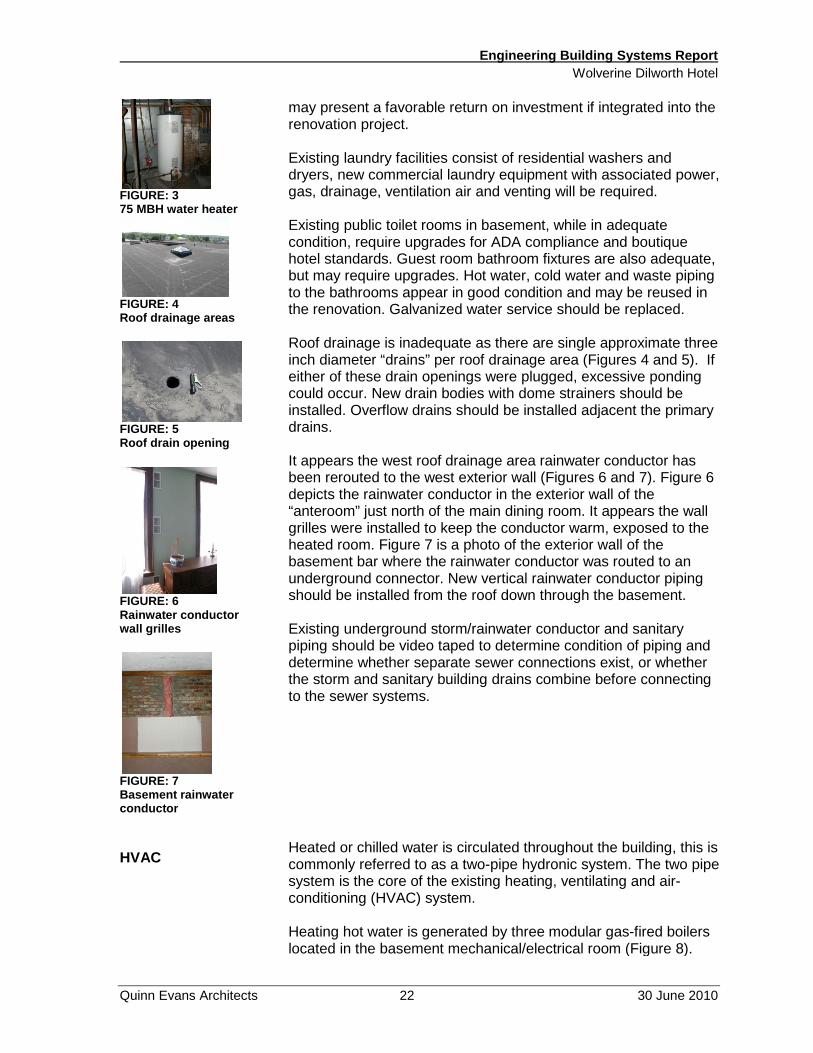
may present a favorable return on investment if integrated into the renovation project. Existing laundry facilities consist of residential washers and dryers, new commercial laundry equipment with associated power, gas, drainage, ventilation air and venting will be required. Existing public toilet rooms in basement, while in adequate condition, require upgrades for ADA compliance and boutique hotel standards. Guest room bathroom fixtures are also adequate, but may require upgrades. Hot water, cold water and waste piping to the bathrooms appear in good condition and may be reused in the renovation. Galvanized water service should be replaced. Roof drainage is inadequate as there are single approximate three inch diameter “drains” per roof drainage area (Figures 4 and 5). If either of these drain openings were plugged, excessive ponding could occur. New drain bodies with dome strainers should be installed. Overflow drains should be installed adjacent the primary drains. It appears the west roof drainage area rainwater conductor has been rerouted to the west exterior wall (Figures 6 and 7). Figure 6 depicts the rainwater conductor in the exterior wall of the “anteroom” just north of the main dining room. It appears the wall grilles were installed to keep the conductor warm, exposed to the heated room. Figure 7 is a photo of the exterior wall of the basement bar where the rainwater conductor was routed to an underground connector. New vertical rainwater conductor piping should be installed from the roof down through the basement. Existing underground storm/rainwater conductor and sanitary piping should be video taped to determine condition of piping and determine whether separate sewer connections exist, or whether the storm and sanitary building drains combine before connecting to the sewer systems. Heated or chilled water is circulated throughout the building, this is commonly referred to as a two-pipe hydronic system. The two pipe system is the core of the existing heating, ventilating and air-conditioning (HVAC) system. Heating hot water is generated by three modular gas-fired boilers located in the basement mechanical/electrical room (Figure 8).

Engineering Building Systems Report Wolverine Dilworth Hotel
Quinn Evans Architects 23 30 June 2010
FIGURE: 8 Boilers
FIGURE: 9 Chiller
FIGURE: 10 AH-1
FIGURE: 11 AH-2
FIGURE: 12 AH-3
FIGURE: 13 Kitchen hood
Chilled water is generated by an air-cooled chiller which sits on grade at the southeast corner of the building Figure 9). There are manual changeover valves located in the basement which determines whether the two-pipe building supply and return water is diverted through the boilers or through the chillers. The major disadvantage of the two-pipe system is there can only be heating hot water or chilled water circulated through the building. Therefore if the west side of the building requires cooling, there will be times when other areas of the building may need heating. The two pipe hydronic system circulating piping is connected to three small air-handling units (AH) located throughout the basement Figures 10, 11 and 12). AH-1 serves the main dining room and lower level bar, AH-2 serves the main floor bar and AH-3 serves the lobby. The two pipe system is also distributed up in two vertical pipe chases to each guest room floor. Each guest room has a fan coil unit concealed above the bathroom ceiling. These units do not have adequate space for maintenance, and have evidence of pipe condensation and drain pan leakage. Guest room bathrooms do not have exhaust. The kitchen cooking appliances are located under a commercial kitchen hood. The hood is a compensating type with make-up air introduced directly into the front of the hood (Figure 13). The hood is provided with a fire suppression system. The kitchen hood grease fan and make-up air unit are located on the addition roof directly above the hood (Figure 14). Current codes do not allow the exhaust fan discharge to occur within 10 feet of an operable window. Possible reuse of the kitchen hood is dependent upon proposed new kitchen appliance type and locations. From HVAC equipment serial numbers and discussions with familiar parties, the two pipe hydronic system was installed around 1989 or 1990. At twenty plus years, the system is nearing the end of its useful service life. Control valves, isolation valves, pumps and piping fittings in the basement appear to be deteriorating. Under the proposed renovation project, the entire existing HVAC system should be replaced. Copper piping mains and branch lines may be reused after further evaluation. Reuse of vertical pipe chases and two pipe hydronic piping mains is possible with a new heat pump heating and cooling system for the renovated facility. The new heat pump system could either be; a “traditional” type with a boiler for supplemental heat in the winter and a cooling tower for supplemental heat rejection in the summer, or a geothermal system which uses the earth for heat exchange. We recommend the installation of a geothermal HVAC system to serve the renovated facility.

Engineering Building Systems Report Wolverine Dilworth Hotel
Quinn Evans Architects 24 30 June 2010
FIGURE: 14 Kit. EF And MAU
FIGURE: 15 Geothermal manifold
FIGURE: 16 Vertical geo heat pump POWER
FIGURE: 17 Service entrance
The geothermal system would consist of a series of vertical boreholes drilled under the parking lot. Within the boreholes, HDPE piping loops would be installed with each loop circuited back to a manifold in the basement. The manifold would serve as the “bridge” between the ground heat exchanger piping circuits and the circulating loop within the building utilizing the existing two pipe hydronic copper mains (Figure 15). Vertical geothermal ground loop heat pump units would be located in the basement to serve first floor and basement zones; main dining room, main floor bar, lobby, kitchen, lower level bar, lower level laundry, lower level employee lounge. An air energy recovery ventilator would be installed to provide code mandated minimum outdoor air ventilation to patron areas and utilize exhaust air to pre-condition the outdoor air through an energy recovery wheel. Each guest room would be provided with a vertical geothermal ground source heat pump which would be recessed within a closet or new enclosure (Figure 16). New guest room thermostats with occupancy sensors would be provided. Federal investment tax credits of 10% for geothermal, accelerated depreciation deductions, and utility rebates may present a favorable return on investment if integrated into the renovation project. Attached at the end of the engineering building systems report section is a basic simple payback analysis with preliminary geothermal HVAC system costs with tax credits and accelerated depreciation which reflects a very favorable return on investment for geothermal HVAC. A 120/240 volt, 3 phase electrical service enters through a current transformer (CT) cabinet at the southeast corner of the building (Figure 17). The 200A (amp) disconnect switch on the right of the cabinet serves the HVAC system chiller. Two four inch conduit enter the basement mechanical /electrical room; one supplies a wireway(Figure 18), while the other supplies a switchboard (Figure 19). The wire way supplies: a 200A branch circuit panel “A” which contains circuit breakers for the elevator and kitchen equipment, enclosed circuit breakers for exit signs, 400A disconnect for wireway extension feeding enclosed circuit breakers for panels

Engineering Building Systems Report Wolverine Dilworth Hotel
Quinn Evans Architects 25 30 June 2010
FIGURE: 18 Wireway
FIGURE: 19 Switchboard
FIGURE: 20 Hazardous panel
FIGURE: 21 Open function box
FIGURE: 22 Old knob and tube wiring LIGHTING
“C”, “D”, “E”, “F”, “G” and “H”. Branch circuit panels C through H are located throughout the basement and first floors. The 800A distribution panel has four 200A two pole switches feeding branch circuit panels located on guest room floors two and three. It appears the distribution panel may be in code violation as there is no means of disconnect for the power feeding the switchboard, and the number of service disconnects exceed code limits. Also, the chilled water piping in front of the switchboard creates a potential hazard as the switchboard does not have code required working clearance to remove the panel front. Other code violations and potential electrical hazards exist; non-code compliant sheet metal panel cover with hazardous wiring methods (Figure 20), and numerous locations of open junction boxes with improperly terminated or abandoned wiring (Figures 21 and 22). During renovations the entire electrical service should be brought into code compliance with proper disconnect means established, code required working clearances, grouping of service disconnects, equipment grounding conductors and system grounding, with all abandoned wireways and conductors removed. Guest room receptacle locations both standard and ground fault type will need to be integrated during renovations with the proposed boutique hotel room finish and interior design standards. Lighting in the basement consists of porcelain lamp holders with primarily screw-in fluorescent lamps, downlights in the lower level bar and lay-in 2x4 fluorescent fixtures. All existing lighting and switching should be removed during renovations. Mechanical/electrical rooms, laundry room, employee lounge and other lower level service areas should be provided with compact fluorescent or lay-in fluorescent fixtures with high efficiency T8 lamps and electronic ballasts. Occupancy sensors should be installed to provide automatic control of service area lighting. Patron areas such as elevator lobby, toilet rooms and the lower level bar should have new lighting fixtures installed to match the

Engineering Building Systems Report Wolverine Dilworth Hotel
Quinn Evans Architects 26 30 June 2010
FIRE ALARM
aesthetics of the first floor period lighting fixtures. First floor patron areas currently have period lighting fixtures and exit signs installed. The light fixtures should be upgraded to meet UL rating requirements. Existing emergency egress lighting is non-code compliant. New recessed downlights with battery back-up should be installed throughout first floor and upper guest room lobbies and corridors to provide emergency egress lighting. Egress pathways leading from the building exits will also need to be provided with emergency egress lighting. The new egress lighting will be integrated with new exterior porch lighting and step lights. New signage lighting, landscape lighting and parking area lighting should be provided with the renovations. The kitchen has lay-in fluorescent fixtures. New fixtures with T8 lamps and high efficiency ballasts should be installed. New combination exit/emergency egress lighting fixtures with battery back-up should be installed throughout the kitchen. Guest room lighting and code compliant lighting controls (occupancy sensors) will need to be integrated during renovations with the proposed boutique hotel room finish and interior design standards. Existing fire alarm for Group R occupancy is non-code compliant as it consists of only smoke detectors. Under renovation the entire building shall be equipped with a automatic fire alarm system throughout egress pathways, and smoke alarms in all sleeping areas and paths of means of egress. The new fire alarm system primary power source shall be the building AC system with battery power as a secondary source. As mentioned in the Fire Protection section above, the new fire suppression system water flow indicators and supervisory valves shall be monitored through the central station fire alarm system. Kitchen hood suppression systems would also be monitored through the fire alarm system.

Wolverine Dilworth HotelGeothermal HVAC System Economic Analysis6/3/2010
Project Data & Assumptions
Building Area: 34,500 sq. ft.Target Annual Energy Savings: $0.60 per sq. ft. per yearTax Rate: 35%Total Geothermal HVAC Sysem Cost: $485,000Premium Cost of Geothermal System: $185,000Target EPACT Tax Deduction ($1.80 max): $1.10 per sq. ft.
Geothermal Incentives
10% Federal Tax Credit (may be taken as a grant) $48,500 (first year only)Cash Benefit of EPACT Tax Deduction $13,283 (first year only)Estimated Annual Energy Savings $20,700 (each year, no inflation)
Depreciable Basis (System Cost ‐ 1/2 Tax Credit) $460,750Year MACRS Depreciation MACRS Depreciation MACRS Tax Benefit1 20% $92,150 $32,2532 32% $147,440 $51,6043 19.2% $88,464 $30,9624 11.52% $53,078 $18,5775 11.52% $53,078 $18,5776 5 76% $26 539 $9 289
Geothermal HVAC System Depreciation Schedule
6 5.76% $26,539 $9,289
Year Annual Cumulative
1 (tax credit, EPACT, MACRS, energy savings) $114,735 $114,7352 MACRS & energy savings $72,304 $187,0393 MACRS & energy savings $51,662 $238,7014 MACRS & energy savings $39,277 $277,9795 MACRS & energy savings $39,277 $317,2566 MACRS & energy savings $29,989 $347,2457 energy savings $20,700 $367,9458 energy savings $20,700 $388,6459 energy savings $20,700 $409,34510 energy savings $20,700 $430,045
Total: $430,045
Cash Flow Analysis
$0
$100,000
$200,000
$300,000
$400,000
$500,000
1 2 3 4 5 6 7 8 9 10
Years In Service
Cumulative Cash Flow & Simple Payback
geo premiumsimple payback


Scope of Work Wolverine Dilworth Hotel
Quinn Evans Architects 29 30 June 2010
SCOPE OF WORK The following scope of work outlines recommended construction
to address deteriorated buildings elements, inadequate building systems, and code violations. It does not include work required to improve the appearance or operational features of the facility. This scope assumes use of the Michigan Rehabilitation Code. Use of the Michigan Building Code may result in additional work. Roofing
• Replace 100% of roof membrane and flashing at upper roof and addition roof.
• Install counter flashing below parapet cap. • Replace limited areas of roof decking; assume 10%. • Replace roof drainage system. • Replace roof hatch. • Replace 100% of roof membrane and flashing at porch
roofs. • Clean out built-in gutters at porch roofs. • Extend downspouts or connect them to perimeter drain
system. Fire Escapes
• Remove the fire escapes. Masonry
• Replace deteriorated brick with new to match. • Repoint deteriorated mortar joints; assume 15% • Reconstruct cheek walls at the porch stairs. • Replace masonry damage where fire escapes are
removed. Cornice
• Replace the missing cornice to match the original. • Repair the remaining cornice. • Paint the cornice.
Porch • Repair the column bases. • Repair the deteriorated ceiling. • Replace deteriorated crown molding to match. • Repair loose steps. • Repaint.

Scope of Work Wolverine Dilworth Hotel
Quinn Evans Architects 30 30 June 2010
Windows
• Repair deteriorated windows. • Prep, prime and paint windows.
Skylights
• Replace cracked panes. • Replace glazing compound. • Paint metal frame.
Exterior Doors
• Replace hardware to meet accessibility requirements. • Replace aluminum doors to the restaurant with historically
appropriate doors.
Emergency Egress at South West Wing • Construct new enclosed emergency egress stairway to
serve all four levels; or • Construct new emergency egress stairs to serve floors one
through three. • Reconfigure egress stairs from the basement to meet
current code requirements. Lobby
• Repair damaged drywall and paint. Stair Hall, Vestibule, Restaurant, Banquet Room
• Remove vents from ante room wall. • Repair damaged drywall and paint. • Replace carpeting to meet requirements of the new
operator. Kitchen
• Replace interior finishes as needed to meet requirements of new operator.
Grand Staircase
• Replace carpeting to meet requirements of the new operator.
• Provide enclosure at one level, so that no more than three levels are connected by the stair.
• Replace/modify handrail to meet ADA guidelines. Corridors at Second and Third Floors
• Replace carpeting to meet requirements of the new operator.
• Reconfigure corridors to convert gathering spaces to

Scope of Work Wolverine Dilworth Hotel
Quinn Evans Architects 31 30 June 2010
rooms only if the gather spaces did not exist historically. Interior Doors
• Replace hardware to meet accessibility requirements. • Install closers or self closing hinges where required by
code. Southeast Stair
• Provide doors and walls to complete enclosure around southeast stair.
• Confirm one hour fire resistant structure at southeast stair. • Improve fire resistant rating of walls and ceilings, if
required. Guest Rooms
• Replace carpeting and wall paper to meet requirements of the new operator.
Basement Bar
• Replace finishes to meet the requirements of the new operator.
Basement Restrooms
• Provide enough fixtures to meet fixture count for restaurant, banquet hall, and bar.
• Modify fixtures to meet accessibility requirements. • Replace finishes to meet the requirements of the new
operator. Elevator
• Replace elevator controls to meet ADA guidelines • Replace finishes to meet the requirements of the new
operator. Basement Utility Areas
• Replace finishes to meet the requirements of the new operator.
Fire Protection
• Install fire protection system through the building. Pipes may be exposed.
• Plan location of exposed pipes to minimize their impact on the historic character of the building.
• Guest room sprinkler heads may be sidewall type which would limit impact within rooms.
Fire Alarm System
• Install fire alarms system throughout the egress system. • Install smoke detectors in the sleeping rooms.

Scope of Work Wolverine Dilworth Hotel
Quinn Evans Architects 32 30 June 2010
• Monitor the fire suppression system. • Monitor the kitchen hood system.
Plumbing
• Replace galvanized water service. • insulate all domestic hot and cold water piping throughout
building • Install 95% energy efficient water heater and storage tank. • Modify or replace plumbing fixtures at basement
restrooms. • Install commercial laundry facilities with associated power,
gas, drainage, ventilation and ventilation air. • Install new roof drainage. • Video connection to sewer to determine its condition. • New water heating system to provide separate hot water
temperature supplies to; laundry (160F), kitchen (140F) and guest rooms (110F) through thermostatic master mixing valves. Provide hot water recirculation system for guest rooms to assure hot water delivery.
HVAC
• Provide exhaust for basement restrooms. • Provide exhausts for guestroom bathrooms. • Install new boilers and cooling tower or geothermal heat
exchanger. • Install heat pumps in each guest room (may require
modifications to closets and floors plans). • Install new heat pumps in the basement to serve public
spaces. • Install fresh air intake and ventilation system for public
spaces. • Provide new kitchen ventilation systems per food service
equipment layout. • Install air energy recovery ventilator.
Electrical
• Reconfigure the 800A distribution panel to meet code. • Relocate the panel or the chilled water piping in front of the
panel. • Provide new receptacles, branch circuit panels • Provide pathways (conduit, junction boxes, etc.) for low
voltage systems (CTV, phone, security, sound systems, etc.).
• Correct numerous electrical code violations. • Replace lighting in service areas of the basement with high
efficiency fluorescent fixtures and occupancy sensors. • Replace lighting fixtures through public areas in the
basement. • Confirm that lighting fixtures throughout the building have

Scope of Work Wolverine Dilworth Hotel
Quinn Evans Architects 33 30 June 2010
required UL rating. • Install emergency lighting with battery back-up throughout
the building. • Install egress signs with battery back-up throughout the
building. • Integrate exterior egress lighting with porch and site
lighting. • Install new site lighting.
Other
• Framing, drywall, and painting to repair damage that is required to accommodate the new HVAC system and ventilation.