führungsachse passive guide axis fdg−...(de) bedienungs− anleitung (en) operating instructions...
TRANSCRIPT

(de) Bedienungs−anleitung
(en) Operating instructions
(es) Instrucciones de utilización
(fr) Notice d’utilisation
(it) Instruzione per l’uso
(sv) Bruksanvisning
FührungsachsePassive guide axis
FDG−...
712 8260612a
Nicht für FDG−...−RFNot for FDG−...−RFNo para FDG−...−RFNon pour FDG−...−RFNon per FDG−...−RFEj för FDG−...−RF
FDG−...−RF
FDG−...
Festo FDG−... 0612a 2
Es�bedeuten/Symbols/Símbolos/Symboles/Simboli/Teckenförklaring:
Einbau und Inbetriebnahme nur von qualifi�ziertem Fachpersonal, gemäß Bedienungs�anleitung.
WarnungWarning, CautionAtenciónAvertissementAvvertenzaVarning
HinweisPlease notePor favor, observarNoteNotaNotera
UmweltAntipollutionReciclajeRecyclageRiciclaggioÅtervinning
ZubehörAccessoriesAccesoriosAccessoiresAccessoriTillbehör
Fitting and commissioning to be carried outby qualified personnel only in accordancewith the operating instructions.
El montaje y la puesta en funcionamiento,debe ser realizado exclusivamente por per�sonal cualificado y siguiendo las instruccio�nes de utilización.
Montage et mise en service uniquement pardu personnel agréé, conformément auxinstructions d’utilisation.
Montaggio e messa in funzione devono es�sere effettuati da personale specializzato edautorizzato in confomità alle istruzioni perl’uso.
Montering och idrifttagning får endast ut�föras av auktoriserad fackkunnig personal ienlighet med denna bruksanvisning.
Deutsch 3. . . . . . . . . . . . . . . . . . . . . . . . . . . . . . . . . . . . . . . . . . . . . . . . . . . . . . . . . . . . . . . . . . . . . .
English 13. . . . . . . . . . . . . . . . . . . . . . . . . . . . . . . . . . . . . . . . . . . . . . . . . . . . . . . . . . . . . . . . . . . . . .
Español 23. . . . . . . . . . . . . . . . . . . . . . . . . . . . . . . . . . . . . . . . . . . . . . . . . . . . . . . . . . . . . . . . . . . . .
Français 33. . . . . . . . . . . . . . . . . . . . . . . . . . . . . . . . . . . . . . . . . . . . . . . . . . . . . . . . . . . . . . . . . . . . .
Italiano 43. . . . . . . . . . . . . . . . . . . . . . . . . . . . . . . . . . . . . . . . . . . . . . . . . . . . . . . . . . . . . . . . . . . . . .
Svenska 53. . . . . . . . . . . . . . . . . . . . . . . . . . . . . . . . . . . . . . . . . . . . . . . . . . . . . . . . . . . . . . . . . . . . .
FDG−...
Festo FDG−... 0612a Deutsch 3
Führungsachse Typ FDG−... Deutsch
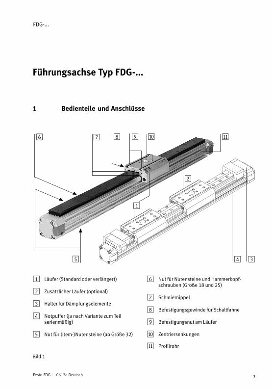
1 Bedienteile und Anschlüsse
1
2
345
aJ87 aA96
1 Läufer (Standard oder verlängert)
2 Zusätzlicher Läufer (optional)
3 Halter für Dämpfungselemente
4 Notpuffer (ja nach Variante zum Teil serienmäßig)
5 Nut für (Item−)Nutensteine (ab Größe 32)
6 Nut für Nutensteine und Hammerkopf�schrauben (Größe 18 und 25)
7 Schmiernippel
8 Befestigungsgewinde für Schaltfahne
9 Befestigungsnut am Läufer
aJ Zentriersenkungen
aA Profilrohr
Bild�1
FDG−...
Festo FDG−... 0612a Deutsch4
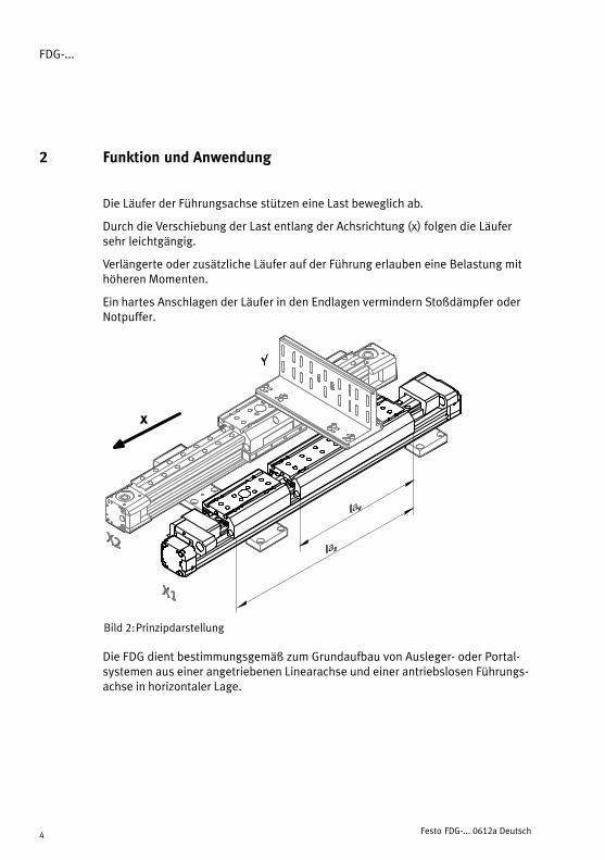
2 Funktion und Anwendung
Die Läufer der Führungsachse stützen eine Last beweglich ab.
Durch die Verschiebung der Last entlang der Achsrichtung (x) folgen die Läufersehr leichtgängig.
Verlängerte oder zusätzliche Läufer auf der Führung erlauben eine Belastung mithöheren Momenten.
Ein hartes Anschlagen der Läufer in den Endlagen vermindern Stoßdämpfer oderNotpuffer.
Bild�2: Prinzipdarstellung
x
Die FDG dient bestimmungsgemäß zum Grundaufbau von Ausleger− oder Portal−systemen aus einer angetriebenen Linearachse und einer antriebslosen Führungs�achse in horizontaler Lage.
FDG−...
Festo FDG−... 0612a Deutsch 5
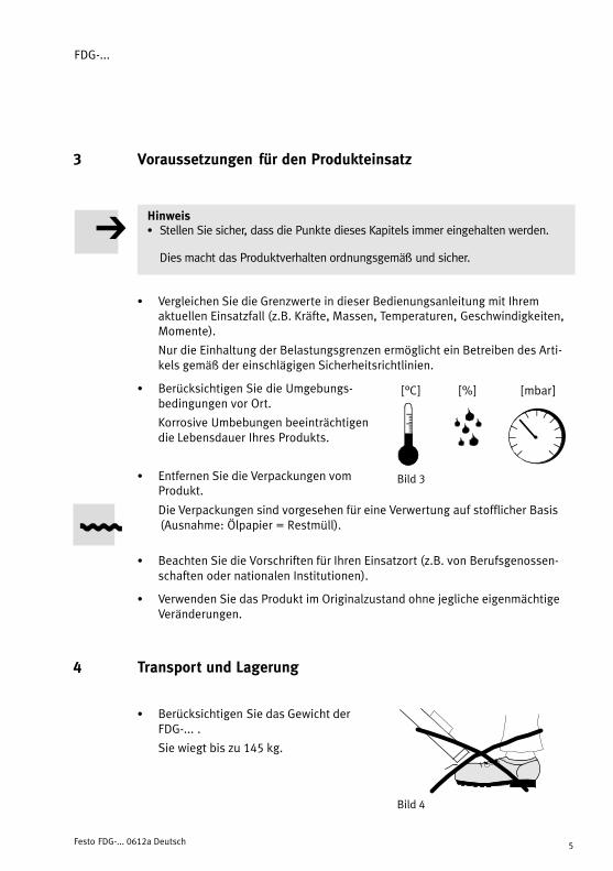
3 Voraussetzungen für den Produkteinsatz
HinweisS Stellen Sie sicher, dass die Punkte dieses Kapitels immer eingehalten werden.
Dies macht das Produktverhalten ordnungsgemäß und sicher.
S Vergleichen Sie die Grenzwerte in dieser Bedienungsanleitung mit Ihremaktuellen Einsatzfall (z.B. Kräfte, Massen, Temperaturen, Geschwindigkeiten,Momente).
Nur die Einhaltung der Belastungsgrenzen ermöglicht ein Betreiben des Arti�kels gemäß der einschlägigen Sicherheitsrichtlinien.
S Berücksichtigen Sie die Umgebungs−bedingungen vor Ort.
Korrosive Umbebungen beeinträchtigendie Lebensdauer Ihres Produkts.
S Entfernen Sie die Verpackungen vom Produkt.
Die Verpackungen sind vorgesehen für eine Verwertung auf stofflicher Basis(Ausnahme: Ölpapier = Restmüll).
S Beachten Sie die Vorschriften für Ihren Einsatzort (z.B. von Berufsgenossen�schaften oder nationalen Institutionen).
S Verwenden Sie das Produkt im Originalzustand ohne jegliche eigenmächtigeVeränderungen.
4 Transport und Lagerung
S Berücksichtigen Sie das Gewicht derFDG−... .
Sie wiegt bis zu 145 kg.
Bild�3
[°C] [%] [mbar]
Bild�4
FDG−...
Festo FDG−... 0612a Deutsch6
5 Einbau
Mechanisch
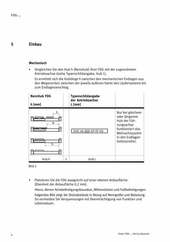
S Vergleichen Sie den Hub h (Nennhub) Ihrer FDG mit der zugeordneten Antriebsachse (siehe Typenschildangabe, Hub L).
Es ermittelt sich die Hublänge h zwischen den mechanischen Endlagen aus den Wegstrecken zwischen der jeweils äußeren Kante des Läufersystems biszum Endlagenanschlag.
Nennhub FDG
h [mm]
Typenschildangabeder AntriebsachseL [mm]
h
h
Nur bei gleichemoder längeremHub der Füh�rungsachse
h
DGE−40−800−SP−KF−GK
rungsachse funktioniert dasMehrachssystemin den Endlagen
h
gkollisionsfrei.
Hub h ≥ Hub L
Bild�5
S Platzieren Sie die FDG waagrecht auf einer ebenen Anbaufläche. (Ebenheit der Anbaufläche 0,2 mm).
Hierzu dienen Achsbefestigungsbausätze, Mittenstützen und Fußbefestigungen.
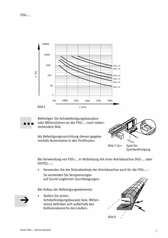
Folgendes Bild zeigt die Stützabstände in Bezug auf Nenngröße und Belastung.So vermeiden Sie Verspannungen mit Beeinträchtigung von Funktion undLebensdauer.
FDG−...
Festo FDG−... 0612a Deutsch 7
Bild�6
500 1000 1500 2000 2500 3000
FDG�25
FDG�32
FDG�40
FDG�18
100
1000
10000
10
1
l [mm]
F[N]
100000
FDG�50
FDG�63
Befestigen Sie Achsbefestigungsbausätzeoder Mittenstützen an der FDG−... nach neben�stehendem Bild.
Als Befestigungsvorrichtung dienen gegebe�nenfalls Nutensteine in den Profilnuten.
Bei Verwendung von FDG−... in Verbindung mit einer Antriebsachse DGE−... oderDGP(L)−...:
S Verwenden Sie die Stützabstände der Antriebsachse auch für die FDG−...:
So vermeiden Sie Verspannungen auf Grund ungleicher Durchbiegungen.
Bei Anbau der Befestigungselemente:
S Stellen Sie sicher:Achsbefestigungsbausatz bzw. Mitten�stütze befinden sich außerhalb des Kollisionsbereichs des Läufers.
ÓÓÓÓÓÓ
Bild�7: Q = Spiel für Querbesfestigung
Bild�8

FDG−...
Festo FDG−... 0612a Deutsch8
S Drehen Sie die Befestigungsschrauben fürdie Querbefestigung zunächst nur leichtfest (siehe Bild 7: Q).
Dadurch lässt sich die FDG−... im weiterenEinbau noch ausrichten.
S Positionieren Sie die FDG−... parallel aus�gerichtet zur angetriebenen Linearachse.
Bei Verwendung von FDG−... in Verbindung mit einer Antriebsachse DGE−.. oderDGP(L)−...:
S Sorgen Sie dafür, dass die Läuferflächenbeider Achsen innerhalb des gesamtenVerfahrhubs auf gleicher Höhe liegen.
S Platzieren Sie die Querverbindung unddie Nutzlast folgendermaßen auf denLäufern von FDG−... und Antriebsachse:
� Es bleibt das Kippmoment aus derKraft F parallel zur Zylinderachse unddem Abstand d klein.Hierbei beinhaltet die Kraft F auch dieTrägheitskraft F = m ⋅ a, Gewichtskraft,und mögliche externe Kraft.
� Es wirken nur Belastungen im Rahmender zulässigen Werte.
Bei Führungsachsen mit mehreren Laufwagen:
S Vergleichen Sie den Abstand zwischenden beiden Läufern mit dem Mindestab�stand amin nach nebenstehendem Bild.
ÓÓÓÓÓÓÓ
ÓÓÓÓBild�9
Bild�10
Bild�11
Bild�12
F F
a a
amin
Bild�13
FDG−...
Festo FDG−... 0612a Deutsch 9
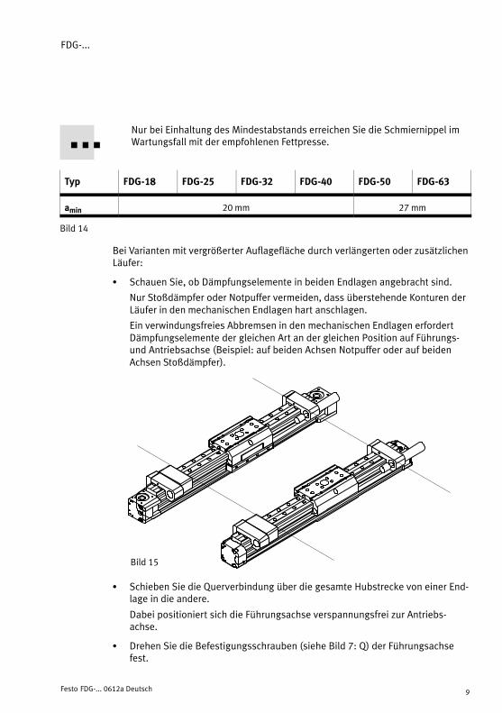
Nur bei Einhaltung des Mindestabstands erreichen Sie die Schmiernippel imWartungsfall mit der empfohlenen Fettpresse.
Typ FDG−18 FDG−25 FDG−32 FDG−40 FDG−50 FDG−63
amin 20 mm 27 mm
Bild�14
Bei Varianten mit vergrößerter Auflagefläche durch verlängerten oder zusätzlichenLäufer:
S Schauen Sie, ob Dämpfungselemente in beiden Endlagen angebracht sind.
Nur Stoßdämpfer oder Notpuffer vermeiden, dass überstehende Konturen derLäufer in den mechanischen Endlagen hart anschlagen.
Ein verwindungsfreies Abbremsen in den mechanischen Endlagen erfordertDämpfungselemente der gleichen Art an der gleichen Position auf Führungs−und Antriebsachse (Beispiel: auf beiden Achsen Notpuffer oder auf beidenAchsen Stoßdämpfer).
Bild�15
S Schieben Sie die Querverbindung über die gesamte Hubstrecke von einer End�lage in die andere.
Dabei positioniert sich die Führungsachse verspannungsfrei zur Antriebs�achse.
S Drehen Sie die Befestigungsschrauben (siehe Bild 7: Q) der Führungsachsefest.

FDG−...
Festo FDG−... 0612a Deutsch10
Zur Abfrage der Läuferpositionen:
S Verwenden Sie Sensoren mit induktivem Schaltprinzip in Verbindung mit ferritischen Schaltfahnen.
Aufgrund des reinen Außenläufers besitzt die FDG−... keinen Magneten.
Ungenutzte Sensornuten schützen Sie am besten mit Abdeckschienen lautKapitel �Zubehör" vor Schmutzablagerungen.
6 Inbetriebnahme
Bei Inanspruchnahme der Notpuffer:
S Schauen Sie, ob die Halterung des Notpuffers verschoben oder asymmetrischverwunden ist.
In diesem Falle ist es notwendig, die Halterung KYP−... neu zu positionieren.
Dabei ist darauf zu achten, die Klemmschrauben wieder gut festzuziehen.
S Ziehen Sie leicht an der Klebeverbindung zwischen Notpuffer und Halter.
Im Falle der Beschädigung von Klebeschicht oder Notpuffer wechseln Sie denNotpuffer komplett.
7 Wartung und Pflege
Zur Schmierung der Wälzlager−Führungen der Typen FDG−...−KF:
S Beachten Sie die Schmierintervalle:
Fettsorte 1. Intervall 2. ... n. Intervall
FDG−8 ... 18 FDG−25 ... 63
Festo Spezialfett LUB−KC1 5000 km 400 km
Festo Spezialfett LUB−RN2 5000 km 400 km 5000 km
Fuchs Notropeen LXG00 5000 km 5000 km unzulässig
Bild�16: Fettsorten und Schmierintervalle

FDG−...
Festo FDG−... 0612a Deutsch 11
S Beachten Sie, dass die Schmierintervalleverkürzt werden müssen bei
� staubiger und schmutziger Umgebung� Nennhüben > 2000 mm oder < 50 mm� Geschwindigkeiten > 2 m/s� Betriebsalter der FDG > 3 Jahre
S Fetten Sie die Läuferlagerung an allenSchmiernippeln 7. Spezialfett und Fett�presse mit Nadel−Spitzmundstück: gemäß�Zubehör".
S Fahren Sie den Verfahrweg während desFettens komplett ab, um das Fett gleich−mäßig im Inneren zu verteilen.
8 Zubehör
Bezeichnung Typ
Mittenunterstützung MUP−...
Stoßdämpferhalter KYP−...
Verbindungsbausatz HMVG−...
Tandembausatz HMVT−...
Tandemauslegerbausatz HMVD−...
Fettpresse mit NadelspitzmundstückDüsenrohr gewinkelt
Teile−Nr. 647958Teile−Nr. 647960
Spezialfett (silikonfrei)Spezialfett (silikonfrei)
LUB−KC1 von Festo *)
LUB−RN2 von Festo *)
*) Siehe Ersatzteilkatalog unter www.festo.com
Bild�18
Bild�17
FDG−18−KF
FDG−...−KF
7
7

FDG−...
Festo FDG−... 0612a Deutsch12
9 Störungsbeseitigung
Störung Ursache Abhilfe
Auffällige Laufgeräusche Mangel−Schmierung der Läufer−lagerung
Nachfetten
Läufer schwergängig Gewindestifte der Wälzkasset�tenjustierung zu stark angezogen
Neu einstellen
Fühlbares Spiel am Läufer Nicht korrekt eingestellt Neu einstellen
Schwergängigkeit einer Tandem−anordnung nahe der Endlage
Mangelnde Parallelität zwischen Antrieb und FDG
Achsen neu aus�richten
Bild�19
10 Technische Daten
FDG−... 18 25 32 40 50 63
Fzmax. [N] 930 3080 3080 7300 7300 14050
Mxmax. [Nm] 7 45 63 170 240 580
Mzmax./Mymax. [Nm] (...−GK/GA) 23 85 127 330 460 910
Mzmax./Mymax. [Nm] (...−GV) 45 170 250 660 920 1820
Vmax. [m/s] 3
|Mx|Mxmax
�|My|Mymax
�|Mz|Mzmax
�|Fy|Fymax
�|Fz|Fzmax
� 1
Bild�20
FDG−...
Festo FDG−... 0612a English 13
Driveless guide axis type FDG−... Deutsch
1 Operating parts and connections
1
2
345
aJ87 aA96
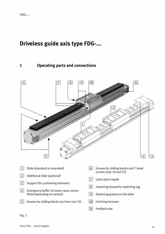
1 Slide (standard or extended)
2 Additional slide (optional)
3 Support for cushioning elements
4 Emergency buffer (in some cases series−fitted depending on variant)
5 Groove for sliding blocks (as from size 32)
6 Groove for sliding blocks and T−headscrews (size 18 and 25)
7 Lubrication nipple
8 Fastening thread for switching tag
9 Fastening groove on the slide
aJ Centring recesses
aA Profiled tube
Fig.�1

FDG−...
Festo FDG−... 0612a English14
2 Method of operation and use
The slides of the guide axis support a moving load.
When the load is shifted in the axis direction (x), the slides follow easily.
Extended or additional slides on the guide permit loading with higher torques.
The slides can be prevented from striking hard against the end positions if shockabsorbers or emergency buffers are used.
Fig.�2: General operating principle
x
The FDG is designed for setting up bracket arm systems consisting of a driven lin�ear axis and a driveless guide axis in a horizontal position.

FDG−...
Festo FDG−... 0612a English 15
3 Conditions of use
Please noteS Make sure that the specifications contained in this section are always observed.
The product will then function reliably and as designated.
S Compare the maximum values specified in these operating instructions withyour current application (e.g. forces, masses, temperatures, speeds, torques).
The product can only be operated in accordance with the relevant safety guide�lines if the maximum specified loading limits are not exceeded.
S Take into account the ambient conditionsat the site.
A corrosive environment will impair theservice life of the product.
S Remove the packaging from the product.
The packing is intended for recycling purposes (except for oiled paper whichmust be disposed of ).
S Observe the safety regulations for your site, as well as national and local lawsand regulations.
S Use the product in its original state without undertaking any modifications.
4 Transport and storage
S Take into account the weight of the FDG−...
It weighs up to 145 kg.
Fig.�3
[°C] [%] [mbar]
Fig.�4

FDG−...
Festo FDG−... 0612a English16
5 Fitting
Mechanical
S Compare the stroke h (Rated stroke) of your FDG with the drive axis assigned(see specifications on type plate).
The stroke length h between the mechanical end positions can be calulatedfrom the length of the paths between the respective outer edge of the slidesystem and the end position stop.
Rated stroke FDG
h [mm]
Type plate specificationof the drive axisL [mm]
h
h
The assignmentwill only functionwithout a colli�sion if the guide
h
DGE−40−800−SP−KF−GK
sion if the guideaxis has an equalor longer stroke.
h
Stroke h ≥ Stroke L
Fig.�5
S Place the FDG horizontally on a level mounting surface (evenness of the surface Rt 0.2 mm).
Axis fastening kits, centre supports and foot fastenings can be used here.
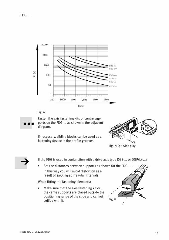
The adjacent diagram shows the distances between supports in relation torated size and loading.
By adhering to these specifications, you will avoid distortion and impairmentof both operation and service life.
FDG−...
Festo FDG−... 0612a English 17
500 1000 1500 2000 2500 3000
FDG�25
FDG�32
FDG�40
FDG�18
100
1000
10000
10
1
l [mm]
F[N]
100000
FDG�50
FDG�63
Fig.�6
Fasten the axis fastening kits or centre sup�ports on the FDG−... as shown in the adjacentdiagram.
If necessary, sliding blocks can be used as afastening device in the profile grooves.
If the FDG is used in conjunction with a drive axis type DGE−... or DGP(L)−...:
S Set the distances between supports as shown for the FDG−... .
In this way you will avoid distortion as aresult of sagging at irregular intervals.
When fitting the fastening elements:
S Make sure that the axis fastening kit orthe cente supports are placed outside thepositioning range of the slide and cannotcollide with it.
ÓÓÓÓÓÓÓÓÓ
Fig.�7: Q = Side play
Fig.�8

FDG−...
Festo FDG−... 0612a English18
S Tighten the fastening screws for diagonalfastening at first only slightly (see Fig. 7: Q).
This enables the FDG−... to be alignedcorrectly before further fitting is under�taken.
S Position the FDG−... parallel to the drivenlinear axis.
If you are using the FDG−... in conjunction with a drive axis type DGE−.. orDGP(L)−...:
S Make sure that the slide surfaces of bothaxes lie at the same height within thecomplete positioning stroke.
S Place the diagonal connection and thework load on the slides of the FDG−... andthe drive axis so that:
� The tilting torque of force F remainsparallel to the cylinder axis and dis�tance d remains small.Force F here contains the inertial forceF = m ⋅ a, force due to weight and anyexternal force.
� Loadings do not exceed the max. per�mitted values.
In the case of guide axes with several slides
S Compare the distance between the twoslides with the minimum distance asshown in the adjacent diagram.
ÓÓÓÓÓÓÓÓÓÓFig.�9
Fig.�10
Fig.�11
Fig.�12
F F
a a
amin
Fig.�13

FDG−...
Festo FDG−... 0612a English 19
You can only reach the lubrication nipple for servicing with the recommended pressure grease gun, if the minumum distance is observed.
Typ FDG−18 FDG−25 FDG−32 FDG−40 FDG−50 FDG−63
amin 20 mm 27 mm
Fig.�14
Variants with larger support surface due to a longer or additional slide:
S Check to see if there are cushioning elements in both end positions.
Projecting contours of the slides can ony be prevented from striking hardagainst the end positions if shock absorbers or emergency buffers are used.
Distortion−free braking in the mechanical end positions demands cushioningelements of the same type in the same position on the guide axis and driveaxis (example: emergency buffers on both axes or shock absorbers on bothaxes).
Fig.�15
S Push the diagonal connection over the complete stroke path from one endposition to the other.
The guide axis can then be positioned free of tension in relation to the driveaxis.
S Now tighten the fastening screws (see Fig. 7: Q) of the guide axis.
FDG−...
Festo FDG−... 0612a English20
In order to scan the slide positions:
S use sensors with inductive switching principle together with ferritic switching tags.
Due to the clean outer slide, the FDG does not possess magnets.
You can protect unused sensor grooves from dust deposits by using cover rails.
6 Commissioning
If the emergency buffers are used:
S Check to see if the support of the emergency buffer is displaced or is damagedasymmetrically.
If this is the case, the support KYP−... must be positioned again.When doing this, make sure that you tighten the clamping screws again.
S Pull gently on the adhesive connection between the emergency buffer and thesupport.
If the adhesive layer or the emergency buffer is damaged, you must replace theemergency buffer completely.
7 Care and maintenance
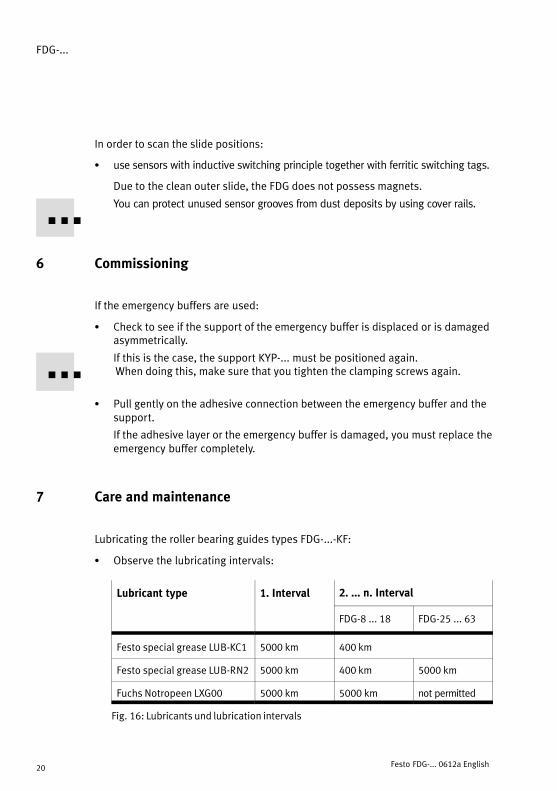
Lubricating the roller bearing guides types FDG−...−KF:
S Observe the lubricating intervals:
Lubricant type 1. Interval 2. ... n. Interval
FDG−8 ... 18 FDG−25 ... 63
Festo special grease LUB−KC1 5000 km 400 km
Festo special grease LUB−RN2 5000 km 400 km 5000 km
Fuchs Notropeen LXG00 5000 km 5000 km not permitted
Fig.�16: Lubricants und lubrication intervals
FDG−...
Festo FDG−... 0612a English 21
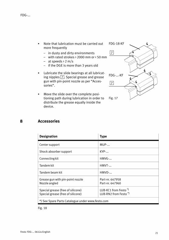
S Note that lubrication must be carried outmore frequently
� in dusty and dirty environments� with rated strokes > 2000 mm or < 50 mm� at speeds > 2 m/s� if the DGE is more than 3 years old
S Lubricate the slide bearings at all lubricat�ing nipples 7. Special grease and greasegun with pin−point nozzle as per �Acces�sories".
S Move the slide over the complete posi�tioning path during lubrication in order todistribute the grease equally inside thedevice.
8 Accessories
Designation Type
Center support MUP−...
Shock absorber support KYP−...
Connecting kit HMVG−...
Tandem kit HMVT−...
Tandem beam kit HMVD−...
Grease gun with pin−point nozzleNozzle angled
Part−nr. 647958Part−nr. 647960
Special grease (free of silicone)Special grease (free of silicone)
LUB−KC1 from Festo *)
LUB−RN2 from Festo *)
*) See Spare Parts Catalogue under www.festo.com
Fig.�18
Fig.�17
FDG−18−KF
FDG−...−KF
7
7
FDG−...
Festo FDG−... 0612a English22
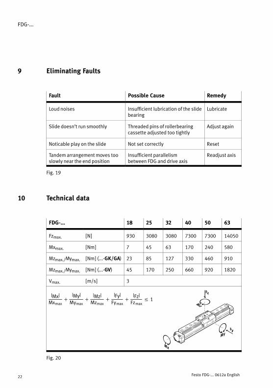
9 Eliminating Faults
Fault Possible Cause Remedy
Loud noises Insufficient lubrication of the slidebearing
Lubricate
Slide doesn’t run smoothly Threaded pins of rollerbearingcassette adjusted too tightly
Adjust again
Noticable play on the slide Not set correctly Reset
Tandem arrangement moves tooslowly near the end position
Insufficient parallelism between FDG and drive axis
Readjust axis
Fig.�19
10 Technical data
FDG−... 18 25 32 40 50 63
Fzmax. [N] 930 3080 3080 7300 7300 14050
Mxmax. [Nm] 7 45 63 170 240 580
Mzmax./Mymax. [Nm] (...−GK/GA) 23 85 127 330 460 910
Mzmax./Mymax. [Nm] (...−GV) 45 170 250 660 920 1820
Vmax. [m/s] 3
|Mx|Mxmax
�|My|Mymax
�|Mz|Mzmax
�|Fy|Fymax
�|Fz|Fzmax
� 1
Fig.�20

FDG−...
Festo FDG−... 0612a Español 23
Eje de guía sin accionamiento, tipo FDG−...Español
1 Elementos funcionales y conexiones
1
2
345
aJ87 aA96
1 Corredera (estándar o ampliada)
2 Corredera adicional (opcional)
3 Soporte para elementos de amortiguación
4 Tope amortiguador de emergencia (en algunos casos, montado de serie según la variante)
5 Ranura para bloques deslizantes (a partir de tamaño 32)
6 Ranura para bloques deslizantes y tornillosen T (tamaño 18 y 25)
7 Boquilla de lubricación
8 Rosca de fijación para la leva del detector
9 Ranura de fijación en la corredera
aJ Rebaje de centrado
aA Tubo perfilado
Fig.�1
FDG−...
Festo FDG−... 0612a Español24
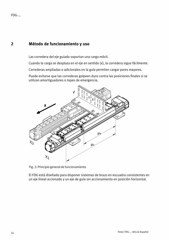
2 Método de funcionamiento y uso
Las corredera del eje guiado soportan una carga móvil.
Cuando la carga se desplaza en el eje en sentido (x), la corredera sigue fácilmente.
Correderas ampliadas o adicionales en la guía permiten cargar pares mayores.
Puede evitarse que las correderas golpeen duro contra las posiciones finales si seutilizan amortiguadores o topes de emergencia.
Fig.�2: Principio general de funcionamiento
x
El FDG está diseñado para disponer sistemas de brazo en escuadra consistentes enun eje lineal accionado y un eje de guía sin accionamiento en posición horizontal.
FDG−...
Festo FDG−... 0612a Español 25
3 Condiciones de uso
Por favor, observar
S Asegúrese de que se observan siempre las especificaciones indicadas enesta sección.
Con ello, el producto funcionará de forma fiable y según lo previsto.
S Compare los valores máximos especificados en estas instrucciones de funcio�namiento con su aplicación actual (p. ej. presiones, fuerzas, pares, temperatu�ras).
El producto sólo puede hacerse funcionar según las correspondientes directri�ces de seguridad si se observan los límites de carga máximos.
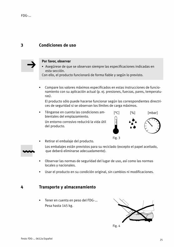
S Ténganse en cuenta las condiciones am�bientales del emplazamiento.
Un entorno corrosivo reducirá la vida útildel producto.
S Retirar el embalaje del producto.
Los embalajes están previstos para su reciclado (excepto el papel aceitado,que deberá eliminarse adecuadamente).
S Observar las normas de seguridad del lugar de uso, así como las normas locales y nacionales.
S Usar el producto en su condición original, sin cambios ni modificaciones.
4 Transporte y almacenamiento
S Tener en cuenta en peso del FDG−...
Pesa hasta 145 kg.
Fig.�3
[°C] [%] [mbar]
Fig.�4

FDG−...
Festo FDG−... 0612a Español26
5 Montaje
Mecánico
S Comparar la carrera h (carrera nominal) del FDG con la del eje actuador asig�nado (ver especificaciones en la placa del tipo).
La longitud de la carrera h entre las posiciones finales mecánicas pueden cal�cularse a partir de la longitud de los recorridos entre el respectivo borde exte�rior del sistema de corredera y el tope de posición final.
Carrera nominalFDGh [mm]
Especificación de la placade tipo del eje con acciona�miento L [mm]
h
h
La asignación solamente fun�cionará sin coli�siones si el eje
h
DGE−40−800−SP−KF−GK
siones si el ejede guía tiene lamisma carrera omayor.
h
y
Carrera h ≥ Carrera L
Fig.�5: Principio general de funcionamiento
S Colocar el FDG horizontalmente en una superficie de montaje nivelada (planitud de la superficie Rt 0,2 mm).
Aquí pueden utilizarse kits de fijación de los ejes, soportes de centraje y fijaciones por pies.
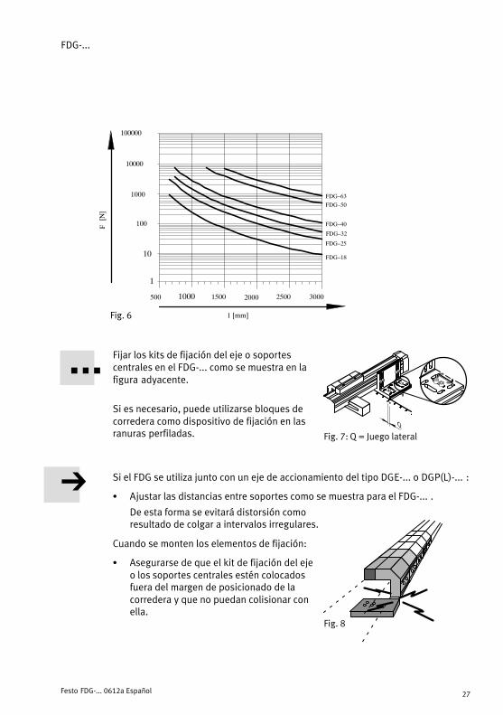
La figura adyacente muestra las distancias entre soportes en relación al tamaño y carga indicados.
Respetando estas especificaciones, se evitarán distorsiones y dificultadestanto en el funcionamiento como en la vida útil.
FDG−...
Festo FDG−... 0612a Español 27
500 1000 1500 2000 2500 3000
FDG�25
FDG�32
FDG�40
FDG�18
100
1000
10000
10
1
l [mm]
F[N]
100000
FDG�50
FDG�63
Fig.�6
Fijar los kits de fijación del eje o soportescentrales en el FDG−... como se muestra en lafigura adyacente.
Si es necesario, puede utilizarse bloques decorredera como dispositivo de fijación en lasranuras perfiladas.
Si el FDG se utiliza junto con un eje de accionamiento del tipo DGE−... o DGP(L)−... :
S Ajustar las distancias entre soportes como se muestra para el FDG−... .
De esta forma se evitará distorsión comoresultado de colgar a intervalos irregulares.
Cuando se monten los elementos de fijación:
S Asegurarse de que el kit de fijación del ejeo los soportes centrales estén colocadosfuera del margen de posicionado de lacorredera y que no puedan colisionar conella.
ÓÓÓÓÓÓÓÓÓ
Fig.�7: Q = Juego lateral
Fig.�8
FDG−...
Festo FDG−... 0612a Español28
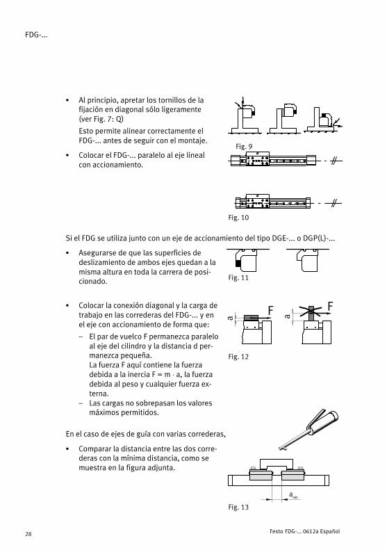
S Al principio, apretar los tornillos de lafijación en diagonal sólo ligeramente(ver Fig. 7: Q)
Esto permite alinear correctamente elFDG−... antes de seguir con el montaje.
S Colocar el FDG−... paralelo al eje lineal con accionamiento.
Si el FDG se utiliza junto con un eje de accionamiento del tipo DGE−... o DGP(L)−...
S Asegurarse de que las superficies de deslizamiento de ambos ejes quedan a lamisma altura en toda la carrera de posi�cionado.
S Colocar la conexión diagonal y la carga detrabajo en las correderas del FDG−... y enel eje con accionamiento de forma que:
� El par de vuelco F permanezca paraleloal eje del cilindro y la distancia d per�manezca pequeña.La fuerza F aquí contiene la fuerza debida a la inercia F = m ⋅ a, la fuerzadebida al peso y cualquier fuerza ex�terna.
� Las cargas no sobrepasan los valoresmáximos permitidos.
En el caso de ejes de guía con varias correderas,
S Comparar la distancia entre las dos corre�deras con la mínima distancia, como semuestra en la figura adjunta.
ÓÓÓÓÓÓÓÓÓÓFig.�9
Fig.�10
Fig.�11
Fig.�12
F F
a a
amín
Fig.�13
FDG−...
Festo FDG−... 0612a Español 29
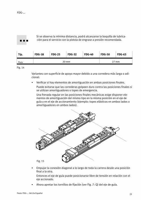
Si se observa la mínima distancia, podrá alcanzarse la boquilla de lubrica�ción para el servicio con la pistola de engrase a presión recomendada.
Típ. FDG−18 FDG−25 FDG−32 FDG−40 FDG−50 FDG−63
amín 20 mm 27 mm
Fig.�14
Variantes con superficie de apoyo mayor debido a una corredera más larga o adi�cional:
S Verificar si hay elementos de amortiguación en ambas posiciones finales.
Puede evitarse que las correderas golpeen duro contra las posiciones finales sise utilizan amortiguadores o topes de emergencia.
Una frenada regular en las posiciones finales mecánicas exige disponer ele�mentos de amortiguación del mismo tipo en la misma posición en el eje deguía y en el eje de accionamiento (ejemplo: topes elásticos en ambos lados oamortiguadores en ambos lados).
Fig.�15
S Empujar la conexión diagonal a lo largo de toda la carrera desde una posiciónfinal a la otra.
Entonces el eje de guía puede posicionarse libre de tensión en relación con eleje accionado.
S Ahora apretar los tornillos de fijación (ver Fig. 7: Q) del eje de guía.

FDG−...
Festo FDG−... 0612a Español30
Para interrogar las posiciones de la corredera:
S usar detectores inductivos con levas de accionamiento ferríticas.
Debido a la corredera exterior limpia, el FDG no posee imanes.
Pueden protegerse de la suciedad las ranuras de sensores que no se utilicen, utilizando tiras de tapa.
6 Puesta a punto
Si se utilizan topes elásticos de emergencia:
S Verificar si el soporte del tope elástico está desplazado o dañado asimétrica�mente.
Si es este el caso, el soporte KYP−... debe posicionarse de nuevo.
Al hacerlo, asegurarse de apretar de nuevo los tornillos de sujeción.
S Tirar suavemente de la conexión adhesiva entre el tope elástico y el soporte.
Si la capa de adhesivo o el tope elástico están dañados, deberá reemplazarcompletamente el tope elástico.
7 Cuidados y mantenimiento
Lubricación de las guías con rodamientos a rodillos tipo FDG−...−KF:
S Observar los intervalos de lubricación:
Tipo de lubricante 1. Intervalo 2. ... n. intervalo
FDG−8 ... 18 FDG−25 ... 63
Festo grasa especial LUB−KC1 5000 km 400 km
Festo grasa especial LUB−RN2 5000 km 400 km 5000 km
Fuchs Notropeen LXG00 5000 km 5000 km no permitida
Fig.�16: Lubricantes y intervalos de lubricación

FDG−...
Festo FDG−... 0612a Español 31
S Observe que la lubricación debe reali�zarse con mayor frecuencia
� en entornos polvorientos y sucios� con carreras > 2000 mm o < 50 mm� a velocidades > 2 m/s� Si el DGE > tiene más de 3 años
S Engrase las rodadudas de la corredera entodas las boquillas de lubricación 7.Grasa especial y bomba de engrase conboquilla de aguja: véase "Accesorios".
S Mientras está engrasando, mueva la co�rredera a lo largo de todo el recorrido deposicionado para distribuir la grasa regu�larmente.
8 Accesorios
Designación Tipo
Soporte central MUP−...
Soporte de amortiguador KYP−...
Kit de conexión HMVG−...
Kit tándem HMVT−...
Kit de unión tándem HMVD−...
Bomba de engrase con boquilla de agujaBoquilla acodada
Nº de artículo 647958Nº de artículo 647960
Grasa especial (sin silicona)Grasa especial (sin silicona)
LUB−KC1 de Festo *)
LUB−RN2 de Festo *)
*) Véase el catálogo de piezas de repuesto en www.festo.com
Fig.�18
Fig.�17
FDG−18−KF
FDG−...−KF
7
7
FDG−...
Festo FDG−... 0612a Español32
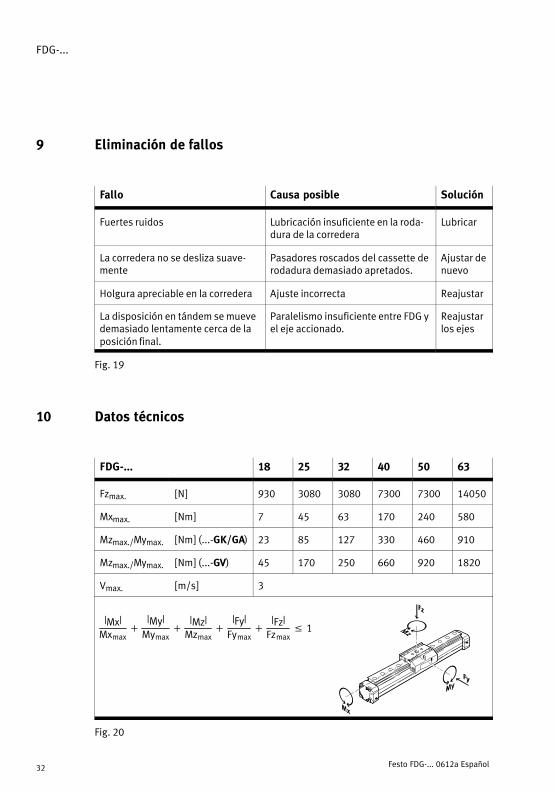
9 Eliminación de fallos
Fallo Causa posible Solución
Fuertes ruidos Lubricación insuficiente en la roda�dura de la corredera
Lubricar
La corredera no se desliza suave�mente
Pasadores roscados del cassette derodadura demasiado apretados.
Ajustar denuevo
Holgura apreciable en la corredera Ajuste incorrecta Reajustar
La disposición en tándem se muevedemasiado lentamente cerca de laposición final.
Paralelismo insuficiente entre FDG yel eje accionado.
Reajustarlos ejes
Fig.�19
10 Datos técnicos
FDG−... 18 25 32 40 50 63
Fzmax. [N] 930 3080 3080 7300 7300 14050
Mxmax. [Nm] 7 45 63 170 240 580
Mzmax./Mymax. [Nm] (...−GK/GA) 23 85 127 330 460 910
Mzmax./Mymax. [Nm] (...−GV) 45 170 250 660 920 1820
Vmax. [m/s] 3
|Mx|Mxmax
�|My|Mymax
�|Mz|Mzmax
�|Fy|Fymax
�|Fz|Fzmax
� 1
Fig.�20
FDG−...
Festo FDG−... 0612a Français 33
Guidage sans entraînement type FDG−... Francais
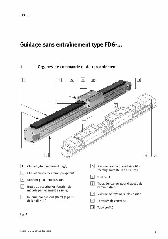
1 Organes de commande et de raccordement
1
2
345
aJ87 aA96
1 Chariot (standard ou rallongé)
2 Chariot supplémentaire (en option)
3 Support pour amortisseurs
4 Butée de securité (en fonction du modèle partiellement en série)
5 Rainure pour écrous (Item) (à partir de la taille 32)
6 Rainure pour écrous et vis à tête rectangulaire (tailles 18 et 25)
7 Graisseur
8 Trous de fixation pour drapeau de commutation
9 Rainure de fixation sur le chariot
aJ Lamages de centrage
aA Tube profilé
Fig.�1
FDG−...
Festo FDG−... 0612a Français34
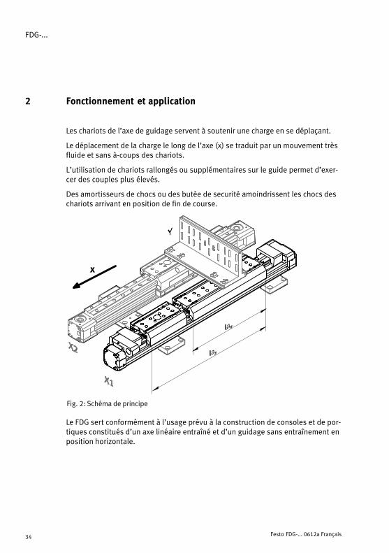
2 Fonctionnement et application
Les chariots de l’axe de guidage servent à soutenir une charge en se déplaçant.
Le déplacement de la charge le long de l’axe (x) se traduit par un mouvement trèsfluide et sans à−coups des chariots.
L’utilisation de chariots rallongés ou supplémentaires sur le guide permet d’exer�cer des couples plus élevés.
Des amortisseurs de chocs ou des butée de securité amoindrissent les chocs deschariots arrivant en position de fin de course.
Fig.�2: Schéma de principe
x
Le FDG sert conformément à l’usage prévu à la construction de consoles et de por�tiques constitués d’un axe linéaire entraîné et d’un guidage sans entraînement enposition horizontale.

FDG−...
Festo FDG−... 0612a Français 35
3 Conditions de mise en �uvre du produit
Note
S Veiller au respect permanent des instructions énoncées dans ce chapitre.
Le respect des instructions garantit un fonctionnement correct et en toute sécurité du produit.
S Comparer au cas réel les valeurs limites indiquées dans cette notice d’utilisa�tion (p. ex. forces, masses, températures, vitesses, couples).
Seul le respect des limites de charge permet un fonctionnement du produitconforme aux directives de sécurité en vigueur.
S Tenir compte des conditions d’environne�ment.
Les atmosphères corrosives réduisent ladurée de vie du produit.
S Enlever les emballages du produit.
Les emballages sont conçus pour queleurs matériaux puissent être recyclés(exception faite du : papier huileux =déchet résiduel).
S Respecter les prescriptions en vigueur sur le lieu d’utilisation (p. ex. venantdes organismes professionnels et réglementations nationales).
S Utiliser le produit dans son état d’origine sans apporter de modifications.
4 Transport et stockage
S Attention, le FDG−... peut peser
jusqu’à 145 kg.
Fig.�3
[°C] [%] [mbar]
Fig.�4
FDG−...
Festo FDG−... 0612a Français36
5 Montage
Mécanique
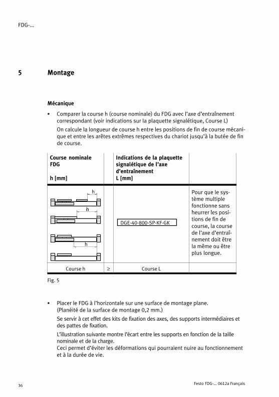
S Comparer la course h (course nominale) du FDG avec l’axe d’entraînementcorrespondant (voir indications sur la plaquette signalétique, Course L)
On calcule la longueur de course h entre les positions de fin de course mécani�que et entre les arêtes extrêmes respectives du chariot jusqu’à la butée de finde course.
Course nominaleFDG
h [mm]
Indications de la plaquettesignalétique de l’axe d’entraînement L [mm]
h
h
Pour que le sys�tème multiplefonctionne sansheurrer les posi
h
DGE−40−800−SP−KF−GK
heurrer les posi�tions de fin decourse, la coursede l’axe d’entraî�
hnement doit êtrela même ou êtreplus longue.
Course h ≥ Course L
Fig.�5
S Placer le FDG à l’horizontale sur une surface de montage plane. (Planéité de la surface de montage 0,2 mm.)
Se servir à cet effet des kits de fixation des axes, des supports intermédiaires etdes pattes de fixation.
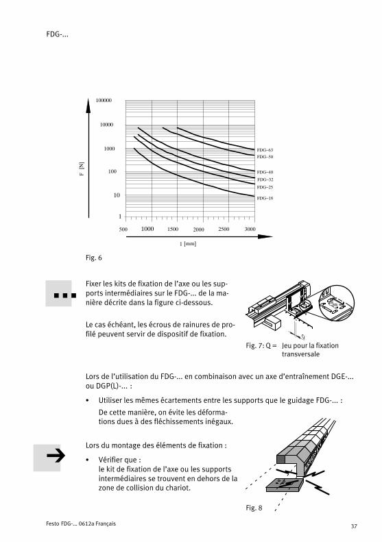
L’illustration suivante montre l’écart entre les supports en fonction de la taillenominale et de la charge.Ceci permet d’éviter les déformations qui pourraient nuire au fonctionnementet à la durée de vie.
FDG−...
Festo FDG−... 0612a Français 37
500 1000 1500 2000 2500 3000
FDG�25
FDG�32
FDG�40
FDG�18
100
1000
10000
10
1
l [mm]
F[N]
100000
FDG�50
FDG�63
Fig.�6
Fixer les kits de fixation de l’axe ou les sup�ports intermédiaires sur le FDG−... de la ma�nière décrite dans la figure ci−dessous.
Le cas échéant, les écrous de rainures de pro�filé peuvent servir de dispositif de fixation.
Lors de l’utilisation du FDG−... en combinaison avec un axe d’entraînement DGE−...ou DGP(L)−... :
S Utiliser les mêmes écartements entre les supports que le guidage FDG−... :
De cette manière, on évite les déforma�tions dues à des fléchissements inégaux.
Lors du montage des éléments de fixation :
S Vérifier que :le kit de fixation de l’axe ou les supportsintermédiaires se trouvent en dehors de lazone de collision du chariot.
ÓÓÓÓÓÓ
Fig.�7: Q = Jeu pour la fixation transversale
Fig.�8
FDG−...
Festo FDG−... 0612a Français38
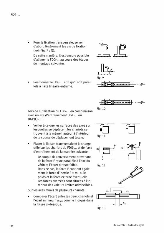
S Pour la fixation transversale, serrerd’abord légèrement les vis de fixation(voir Fig. 7 : Q).
De cette manière, il est encore possibled’aligner le FDG−... au cours des étapes de montage suivantes.
S Positionner le FDG−... afin qu’il soit paral�lèle à l’axe linéaire entraîné.
Lors de l’utilisation du FDG−... en combinaisonavec un axe d’entraînement DGE−... ouDGP(L)−... :
S Veiller à ce que les surfaces des axes surlesquelles se déplacent les chariots setrouvent à la même hauteur à l’intérieurde la course de déplacement totale.
S Placer la liaison transversale et la chargeutile sur les chariots du FDG−... et de l’axed’entraînement de la manière suivante :
� Le couple de renversement provenantde la force F reste parallèle à l’axe duvérin et l’écart d reste faible. Dans ce cas, la force F contient égale�ment la force d’inertie F = m ⋅ a, lepoids et la force externe éventuelle.
� Les forces exercées sont situées à l’in�térieur des valeurs limites admissibles.
Sur les axes munis de plusieurs chariots :
S Comparer l’écart entre les deux chariots etl’écart minimum amin comme indiqué dansla figure ci−dessous.
ÓÓÓÓÓÓÓ
ÓÓÓÓFig.�9
Fig.�10
Fig.�11
Fig.�12
F F
a a
amin
Fig.�13

FDG−...
Festo FDG−... 0612a Français 39
En cas de maintenance, seul le respect de l’écart minimum permet d’atteindrele graisseur à l’aide de la pompe à graisse recommandée.
Type FDG−18 FDG−25 FDG−32 FDG−40 FDG−50 FDG−63
amin 20 mm 27 mm
Fig.�14
Sur les modèles possédant une surface d’appui plus grande du fait de l’utilisationd’un chariot allongé ou supplémentaire :
S Vérifier si les éléments d’amortissement sont montré aux deux fins de course.
Seuls les amortisseurs ou les tampons de securité évitent que les contoursdépassant du chariot ne frappent violemment contre les fins de course mécani�ques.
Pour obtenir un ralentissement sans torsion dans les positions de fin de coursemécaniques, il faut utiliser des éléments amortisseurs de même type et dansla même position sur les axes de guidage et d’entraînement (exemple : tam�pons de securité ou amortisseurs sur les deux axes).
Fig.�15
S Pousser la liaison transversale d’une position de fin de course à l’autre surl’ensemble de la course.
L’axe de guidage se positionne alors sans déformation par rapport à l’axe d’entraînement.
S Visser à fond les vis de fixation (voir Fig. 7 : Q) de l’axe de guidage.

FDG−...
Festo FDG−... 0612a Français40
Pour détecter la position des chariots :
S Utiliser des capteurs de type inductif à détection magnétique.
En raison d’un seul chariot externe, le FDG−... ne possède pas d’aimants.
Pour protéger les rainures de capteurs non utilisées contre les dépôt de pous�sieres, les obturer avec des caches pour rainure, voir chapitre Accessoires.
6 Mise en service
En cas de sollicitation du tampon de securité :
S Vérifier si le support du tampon de securité est déplacé ou endommagé defaçon asymétrique.
Dans ce cas, repositionner le support KYP−...
Veiller à bien serrer les vis de serrage.
S Tirer légèrement sur le joint collé entre le tampon de securité et le support.
En cas de détérioration de la couche adhésive ou du tampon de securité, rem�placer le tampon de securité dans sa totalité.
7 Maintenance et entretien
Pour le graissage des guidages à roulements de type FDG−...−KF :
S Tenir compte des intervalles de graissage :
Type graisse 1er intervalle 2e ... n intervalle
FDG−8 ... 18 FDG−25 ... 63
Festo graisse spéciale LUB−KC1 5000 km 400 km
Festo graisse spéciale LUB−RN2 5000 km 400 km 5000 km
Fuchs Notropeen LXG00 5000 km 5000 km interdit
Fig.�16: Graisses et intervalles de graissage
FDG−...
Festo FDG−... 0612a Français 41
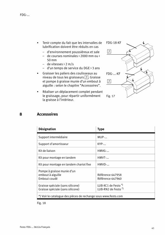
S Tenir compte du fait que les intervalles delubrification doivent être réduits en cas
� d’environnement poussiéreux et sale� de courses nominales > 2000 mm ou <
50 mm� de vitesses > 2 m/s� d’un temps de service du DGE > 3 ans
S Graisser les paliers des coulisseaux auniveau de tous les graisseurs 7. Graisseet pompe à graisse munie d’un embout àaiguille : selon le chapitre "Accessoires".
S Réaliser un déplacement complet pendantle graissage, pour répartir uniformémentla graisse à l’intérieur.
8 Accessoires
Désignation Type
Support intermédiaire MUP−...
Support d’amortisseur KYP−...
Kit de liaison HMVG−...
Kit pour montage en tandem HMVT−...
Kit pour montage en tandem chariot fixe HMVD−...
Pompe à graisse munie d’un embout à aiguilleEmbout coudé
Référence 647958Référence 647960
Graisse spéciale (sans silicone)Graisse spéciale (sans silicone)
LUB−KC1 de Festo *)
LUB−RN2 de Festo *)
*) Voir le catalogue des pièces de rechange sous www.festo.com
Fig.�18
Fig.�17
FDG−18−KF
FDG−...−KF
7
7
FDG−...
Festo FDG−... 0612a Français42
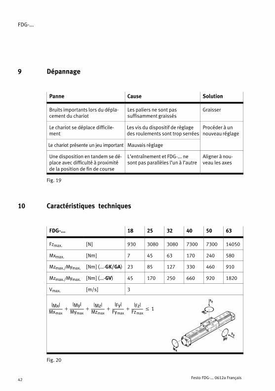
9 Dépannage
Panne Cause Solution
Bruits importants lors du dépla�cement du chariot
Les paliers ne sont pas suffisamment graissés
Graisser
Le chariot se déplace difficile�ment
Les vis du dispositif de réglagedes roulements sont trop serrées
Procéder à unnouveau réglage
Le chariot présente un jeu important Mauvais réglage
Une disposition en tandem se dé�place avec difficulté à proximitéde la position de fin de course
L’entraînement et FDG−... nesont pas parallèles l’un à l’autre
Aligner à nou�veau les axes
Fig.�19
10 Caractéristiques techniques
FDG−... 18 25 32 40 50 63
Fzmax. [N] 930 3080 3080 7300 7300 14050
Mxmax. [Nm] 7 45 63 170 240 580
Mzmax./Mymax. [Nm] (...−GK/GA) 23 85 127 330 460 910
Mzmax./Mymax. [Nm] (...−GV) 45 170 250 660 920 1820
Vmax. [m/s] 3
|Mx|Mxmax
�|My|Mymax
�|Mz|Mzmax
�|Fy|Fymax
�|Fz|Fzmax
� 1
Fig.�20

FDG−...
Festo FDG−... 0612a Italiano 43
Asse di guida non motorizzato tipo FDG−... Italiano
1 Elementi operativi e attacchi
1
2
345
aJ87 aA96
1 Cursore (standard o allungato)
2 Cursore supplementare (optional)
3 Supporto per elementi di ammortizzazione
4 Ammortizzatore di emergenza (a volte di serie, a seconda delle varianti)
5 Scanalatura per tassello scorrevole (dalla misura 32)
6 Scanalatura per tassello scorrevole e vitecon testa a martello (misure 18 e 25)
7 Nipplo per lubrificazione
8 Filettatura di fissaggio per blocchetto diconnessione
9 Scanalatura di fissaggio sul cursore
aJ Lamatura di centratura
aA Canna profilata
Fig.�1
FDG−...
Festo FDG−... 0612a Italiano44
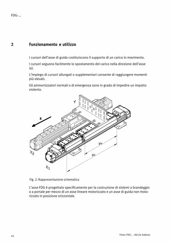
2 Funzionamento e utilizzo
I cursori dell’asse di guida costituiscono il supporto di un carico in movimento.
I cursori seguono facilmente lo spostamento del carico nella direzione dell’asse(x).
L’impiego di cursori allungati o supplementari consente di raggiungere momentipiù elevati.
Gli ammortizzatori normali o di emergenza sono in grado di impedire un impattoviolento.
Fig.�2: Rappresentazione schematica
x
L’asse FDG è progettato specificamente per la costruzione di sistemi a brandeggioo a portale per mezzo di un asse lineare motorizzato e un asse di guida non moto�rizzato in posizione orizzontale.
FDG−...
Festo FDG−... 0612a Italiano 45
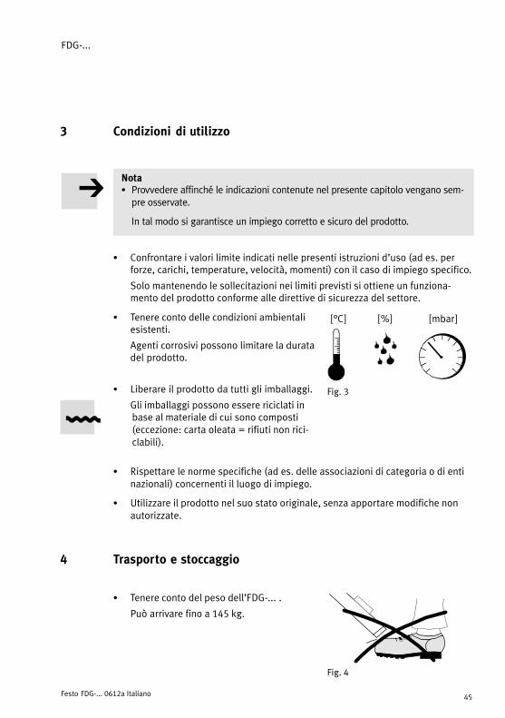
3 Condizioni di utilizzo
NotaS Provvedere affinché le indicazioni contenute nel presente capitolo vengano sem�pre osservate.
In tal modo si garantisce un impiego corretto e sicuro del prodotto.
S Confrontare i valori limite indicati nelle presenti istruzioni d’uso (ad es. perforze, carichi, temperature, velocità, momenti) con il caso di impiego specifico.
Solo mantenendo le sollecitazioni nei limiti previsti si ottiene un funziona�mento del prodotto conforme alle direttive di sicurezza del settore.
S Tenere conto delle condizioni ambientaliesistenti.
Agenti corrosivi possono limitare la duratadel prodotto.
S Liberare il prodotto da tutti gli imballaggi.
Gli imballaggi possono essere riciclati inbase al materiale di cui sono composti(eccezione: carta oleata = rifiuti non rici�clabili).
S Rispettare le norme specifiche (ad es. delle associazioni di categoria o di entinazionali) concernenti il luogo di impiego.
S Utilizzare il prodotto nel suo stato originale, senza apportare modifiche nonautorizzate.
4 Trasporto e stoccaggio
S Tenere conto del peso dell’FDG−... .
Può arrivare fino a 145 kg.
Fig.�3
[°C] [%] [mbar]
Fig.�4
FDG−...
Festo FDG−... 0612a Italiano46
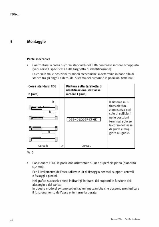
5 Montaggio
Parte meccanica
S Confrontare la corsa h (corsa standard) dell’FDG con l’asse motore accoppiato(vedi corsa L specificata sulla targhetta di identificazione).
La corsa h tra le posizioni terminali meccaniche si determina in base alla di�stanza tra gli angoli esterni del sistema del cursore e le posizioni terminali.
Corsa standard FDG
h [mm]
Dicitura sulla targhetta diidentificazione dell’assemotore L [mm]
h
h
Il sistema mul�tiassiale fun�ziona senza peri�colo di collisioni
h
DGE−40−800−SP−KF−GK
colo di collisioninelle posizioniterminali solo sela corsa dell’asse
hdi guida è mag�giore o uguale.
Corsa h ≥ Corsa L
Fig.�5
S Posizionare l’FDG in posizione orizzontale su una superficie piana (planarità0,2 mm).
Per il livellamento dell’asse utilizzare kit di fissaggio per assi, supporti centrali e fissaggi a piedini.
Nel grafico successivo sono indicati gli interassi dei supporti in funzione dell’alesaggio e del carico.In questo modo si evitano sollecitazioni meccaniche che possono pregiudicareil funzionamento dell’asse e limitarne la durata.

FDG−...
Festo FDG−... 0612a Italiano 47
500 1000 1500 2000 2500 3000
FDG�25
FDG�32
FDG�40
FDG�18
100
1000
10000
10
1
l [mm]
F[N]
100000
FDG�50
FDG�63
Fig.�6
Per il montaggio dei kit di fissaggio o dei supporti centrali sull’FDG−... fare riferimentoal disegno a fianco.
Per il fissaggio si possono montare anche itasselli scorrevoli nelle scanalature profilate.
Utilizzo dell’FDG−... accoppiato a un asse motore DGE−... o DGP(L)−... :
S Montare i supporti dell’asse motore con lo stesso interasse scelto per l’FDG−... .
In questo modo si esclude la possibilità di sollecitazioni meccanichedovute alla presenza di flessioni disuguali.
Montaggio degli elementi di fissaggio
S Verificare quanto segue:Il kit di fissaggio per assi e il supportocentrale devono trovarsi al di fuoridell’area di collisione del cursore.
ÓÓÓÓÓÓ
Fig.�7: Q = Gioco per fissaggio trasversale
Fig.�8

FDG−...
Festo FDG−... 0612a Italiano48
S Fissare le viti per il fissaggio trasversale inun primo tempo senza stringerle a fondo(v. Fig. 7: Q).
In questo modo è possibile equilibrarel’FDG−... in un momento successivo.
S Posizionare l’FDG−... parallelamenteall’asse lineare motorizzato.
Utilizzo dell’FDG−... in combinazione con un asse motore DGE−... o DGP(L)−... :
S Accertarsi che le superfici dei cursori di entrambi gli assi si trovino all’internodella corsa di traslazione totale alla stessaaltezza.
S Posizionare il giunto di accoppiamentotrasversale e il carico sui cursori dell’FDG−... e dell’asse motore come segue:
� La coppia di ribaltamento residua risul�tante dalla forza F parallela all’asse delcilindro e dalla distanza d è esigua.La forza F contiene anche la forza diinerzia F = m ⋅ a, la forza gravimetrica,e possibili forze esterne.
� Le sollecitazioni presenti rientranosempre nei valori ammessi.
In caso di utilizzo di assi di guida con più carrelli: Confrontare la distanza tra i due cursori con ladistanza minima amin, facendo riferimento aldisegno a fianco.
ÓÓÓÓÓÓÓ
ÓÓÓÓFig.�9
Fig.�10
Fig.�11
Fig.�12
F F
a a
amin
Fig.�13

FDG−...
Festo FDG−... 0612a Italiano 49
Solo se è presente la distanza minima, risulta accessibile il nipplo per la lubrifica�zione mediante l’ingrassatore consigliato durante le operazioni di manutenzione.
Tipo FDG−18 FDG−25 FDG−32 FDG−40 FDG−50 FDG−63
amin. 20 mm 27 mm
Fig.�14
Se si utilizzano varianti con superfici di fissaggio maggiorate per la presenza delcursore allungato o supplementare:
S Verificare che siano presenti elementi di ammortizzazione ad entrambe leestremità.
Solo gli ammortizzatori o gli ammortizzatori di emergenza sono in grado diimpedire che il profilo sporgente del cursore abbia un impatto violento contro ifinecorsa meccanici.
Per evitare deformazioni durante la decelerazione nelle posizioni terminali mecca�niche, assicurarsi che sull’asse di guida e sull’asse motore siano presenti elementidi ammortizzazione dello stesso tipo, in posizioni analoghe (esempio: solo ammor�tizzatori di emergenza o solo ammortizzatori in entrambi gli assi).
Fig.�15
S Spingere il giunto di accoppiamento trasversale da un fine corsa all’altro, per�correndo tutta la corsa.
In questo modo l’asse di guida si posiziona adeguandosi all’asse motore,senza sollecitazioni meccaniche.
S Stringere le viti di fissaggio (v. Fig. 7: Q) dell’asse di guida.
FDG−...
Festo FDG−... 0612a Italiano50
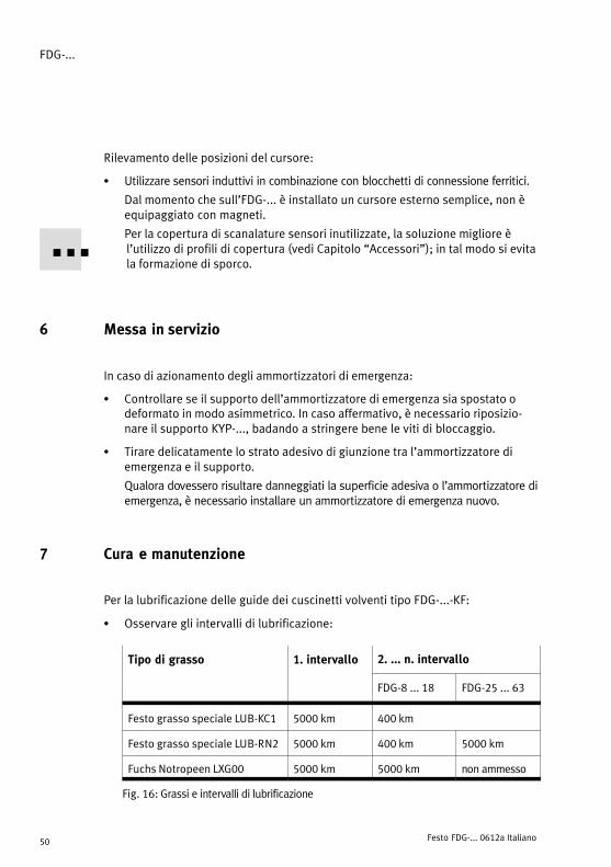
Rilevamento delle posizioni del cursore:
S Utilizzare sensori induttivi in combinazione con blocchetti di connessione ferritici.
Dal momento che sull’FDG−... è installato un cursore esterno semplice, non èequipaggiato con magneti.
Per la copertura di scanalature sensori inutilizzate, la soluzione migliore è l’utilizzo di profili di copertura (vedi Capitolo �Accessori"); in tal modo si evitala formazione di sporco.
6 Messa in servizio
In caso di azionamento degli ammortizzatori di emergenza:
S Controllare se il supporto dell’ammortizzatore di emergenza sia spostato odeformato in modo asimmetrico. In caso affermativo, è necessario riposizio�nare il supporto KYP−..., badando a stringere bene le viti di bloccaggio.
S Tirare delicatamente lo strato adesivo di giunzione tra l’ammortizzatore diemergenza e il supporto.
Qualora dovessero risultare danneggiati la superficie adesiva o l’ammortizzatore diemergenza, è necessario installare un ammortizzatore di emergenza nuovo.
7 Cura e manutenzione
Per la lubrificazione delle guide dei cuscinetti volventi tipo FDG−...−KF:
S Osservare gli intervalli di lubrificazione:
Tipo di grasso 1. intervallo 2. ... n. intervallo
FDG−8 ... 18 FDG−25 ... 63
Festo grasso speciale LUB−KC1 5000 km 400 km
Festo grasso speciale LUB−RN2 5000 km 400 km 5000 km
Fuchs Notropeen LXG00 5000 km 5000 km non ammesso
Fig.�16: Grassi e intervalli di lubrificazione

FDG−...
Festo FDG−... 0612a Italiano 51
S Verificare l’opportunità di aumentare lafrequenza delle lubrificazioni in caso di
� ambiente polverosa e sporca� corse nominali > 2000 mm o < 50 mm� velocità > 2 m/s� età d’esercizo del DGE > 3 anni
S Ingrassare i cuscinetti del cursore su tuttii nippli di lubrificazione 7. Grasso spe�ciale e ingrassatore con punta ad ago:vedi "Accessori".
S Percorrere completamente la corsa ditraslazione durante la lubrificazione perdistribuire uniformemente il grassonell’interno.
8 Accessori
Significato Tipo
Supporto centrale MUP−...
Supporto ammortizzatore KYP−...
Kit di raccordi HMVG−...
Kit per sistemi tandem HMVT−...
Kit per sistemi tandem a brandeggio HMVD−...
Ingrassatore con punta ad agoLancia a gomito
Cod. prod. 647958Cod. prod. 647960
Grasso speciale (senza silicone)Grasso speciale (senza silicone)
LUB−KC1 Festo *)
LUB−RN2 Festo *)
*) Vedi catalogo parti di ricambio all’indirizzo www.festo.com
Fig.�18
Fig.�17
FDG−18−KF
FDG−...−KF
7
7
FDG−...
Festo FDG−... 0612a Italiano52
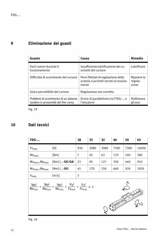
9 Eliminazione dei guasti
Guasto Causa Rimedio
Forti rumori durante il funzionamento
Insufficiente lubrificazione dei cu�scinetti del cursore
Lubrificare
Difficoltà di scorrimento del cursore Perni filettati di regolazione dellascatola cuscinetti serrati eccessiva�mente
Ripetere laregola�zione
Gioco percettibile del cursore Regolazione non corretta
Problemi di scorrimento di un sistematandem in prossimità del fine corsa
Errore di parallelismo tra l’FDG−... el’attuatore
Riallinearegli assi
Fig.�19
10 Dati tecnici
FDG−... 18 25 32 40 50 63
Fzmax. [N] 930 3080 3080 7300 7300 14050
Mxmax. [Nm] 7 45 63 170 240 580
Mzmax./Mymax. [Nm] (...−GK/GA) 23 85 127 330 460 910
Mzmax./Mymax. [Nm] (...−GV) 45 170 250 660 920 1820
Vmax. [m/s] 3
|Mx|Mxmax
�|My|Mymax
�|Mz|Mzmax
�|Fy|Fymax
�|Fz|Fzmax
� 1
Fig.�20

FDG−...
Festo FDG−... 0612a Svenska 53
Passiv linjärenhet typ FDG−... Svenska
1 Detaljer och anslutningar
1
2
345
aJ87 aA96
1 Åkvagn (standard eller förlängd)
2 Extra åkvagn, (tillval)
3 Hållare för stötdämpare
4 Nödbuffert (beroende på variant i vissa fall serieanpassad)
5 Spår för spårmuttrar (fr.o.m. storlek 32)
6 Spår för spårmuttrar och hammarhuvuds�skruvar (storlek 18 och 25)
7 Smörjnipplar
8 Fästgänga för givarkam
9 Spårmutterspår på åkvagnen
aJ Centreringsförsänkning
aA Profilrör
Bild�1
FDG−...
Festo FDG−... 0612a Svenska54
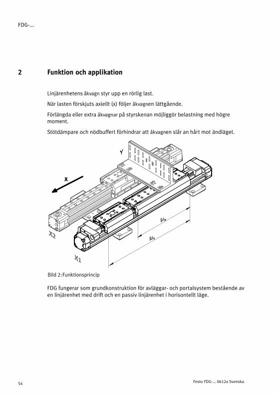
2 Funktion och applikation
Linjärenhetens åkvagn styr upp en rörlig last.
När lasten förskjuts axiellt (x) följer åkvagnen lättgående.
Förlängda eller extra åkvagnar på styrskenan möjliggör belastning med högre moment.
Stötdämpare och nödbuffert förhindrar att åkvagnen slår an hårt mot ändläget.
Bild�2: Funktionsprincip
x
FDG fungerar som grundkonstruktion för avläggar− och portalsystem bestående aven linjärenhet med drift och en passiv linjärenhet i horisontellt läge.

FDG−...
Festo FDG−... 0612a Svenska 55
3 Förutsättningar för korrekt användning av produkten
Notera
S Säkerställ att punkterna i detta kapitel alltid följs.
Detta gör att produkten fungerar korrekt och säkert.
S Jämför gränsvärdena i denna bruksanvisning med din aktuella applikation (t exmassor, krafter, hastigheter, moment och temperaturer).
Endast när belastningsgränserna beaktas kan produkten användas enligt till�lämpliga säkerhetsriktlinjer.
S Ta hänsyn till rådande omgivningsförhål�landen.
Korrosiva omgivningar påverkar produk�tens livslängd.
S Avlägsna produktförpackningar.
Förpackningarna kan återvinnas (undantag: oljepapper = restavfall).
S Följ gällande lagar och förordningar för din applikationsort (t ex säkerhetsföreskrifter).
S Använd produkten i originalskick utan egna modifieringar.
4 Transport och lagring
S Observera tyngden av FDG−...:
Den väger upp till 145 kg.
Bild�3
[°C] [%] [mbar]
Bild�4

FDG−...
Festo FDG−... 0612a Svenska56
5 Montering
Mekanisk
S Jämför slaget h (nominellt slag) på din FDG med tilldelad drivande linjärenhet(se märkskyltens uppgifter, slag L).
Slaglängden h mellan de mekaniska ändlägena kan beräknas sorn sträckanmellan löparsystemets respektive yttersta kant och ändlägesanslaget.
Nominellt slag FDG
h [mm]
Märkskyltens uppgifterpå den drivande linjärenhe�ten L [mm]
h
h
Fleraxelsystemetfungerar endastkollisionsfritt iändlägena om
h
DGE−40−800−SP−KF−GK
ändlägena omlinjärenheten harlika lång ellerlängre slaglängd.
h
g g g
Slag h ≥ Slag L
Bild�5
S Montera FDG horisontellt på en jämn yta. (Monteringsytans jämnhet 0,2 mm.)
För detta används byggsatser för axelinfästning, mittstöd och fotfästen.
Följande diagram visar stödens avstånd vad beträffar nominell storlek och belast�ning. Genom att följa dessa angivelser undviker du dragspänning och försäm�ring av både funktion och livslängd.

FDG−...
Festo FDG−... 0612a Svenska 57
500 1000 1500 2000 2500 3000
FDG�25
FDG�32
FDG�40
FDG�18
100
1000
10000
10
1
l [mm]
F[N]
100000
FDG�50
FDG�63
Bild�6
Fäst byggsatsen för axelinfästning eller mitt�stöd på FDG−... enligt vidstående bild.
Spårmuttrar kan om nödvändigt tjäna somfästanordningar i profilspåren.
Vid användning av FDG−... i kombination med linjärenhet DGE−... eller DGP(L)−...:
S Ställ in linjärenhetens stödavstånd även för FDG−...:
På så sätt undviker du dragspänningp.g.a. ojämn nedböjning.
Vid montering av fästelementen:
S Se till att:Byggsatsen för axelinfästning resp mitt�stödet befinner sig utanför löparens kolli�sionsområde.
ÓÓÓÓÓÓ
Bild�7: Q = Spelrum i sidled
Bild�8
FDG−...
Festo FDG−... 0612a Svenska58
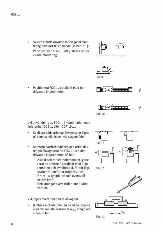
S Skruva in fästskruvarna för diagonal mon�tering bara löst till en början (se bild 7: Q).
På så sätt kan FDG−... lätt justeras undervidare montering.
S Positionera FDG−... parallellt med dendrivande linjärenheten.
Vid användning av FDG−... i kombination med linjärenhet DGE−... eller DGP(L)−...:
S Se till att båda axlarnas åkvagnsytor liggerpå samma höjd inom hela slagområdet.
S Montera tvärförbindelsen och arbetslas�ten på åkvagnarna för FDG−... och dendrivande linjärenheten så här:
� Axiellt och radiellt vridmoment, gene�rerat av kraften F parallellt med linjä�renheten och avståndet d, förblir lågt.Kraften F innefattar tröghetskraft F = m ⋅ a, tyngdkraft och eventuellextern kraft.
� Belastningar överskrider inte tillåtnavärden.
Vid linjärenheter med flera åkvagnar:
S Jämför avståndet mellan de båda löparnamed det minsta avståndet amin enligt vid�stående bild.
ÓÓÓÓÓÓÓ
ÓÓÓÓBild�9
Bild�10
Bild�11
Bild�12
F F
a a
amin
Bild�13
FDG−...
Festo FDG−... 0612a Svenska 59
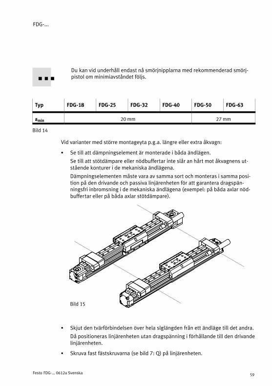
Du kan vid underhåll endast nå smörjnipplarna med rekommenderad smörj�pistol om minimiavståndet följs.
Typ FDG−18 FDG−25 FDG−32 FDG−40 FDG−50 FDG−63
amin 20 mm 27 mm
Bild�14
Vid varianter med större montageyta p.g.a. längre eller extra åkvagn:
S Se till att dämpningselement är monterade i båda ändlägen.
Se till att stötdämpare eller nödbuffertar inte slår an hårt mot åkvagnens ut�stående konturer i de mekaniska ändlägena.
Dämpningselementen måste vara av samma sort och monteras i samma posi�tion på den drivande och passiva linjärenheten för att garantera dragspän�ningsfri inbromsning i de mekaniska ändlägena (exempel: på båda axlar nöd�buffertar eller på båda axlar stötdämpare).
Bild�15
S Skjut den tvärförbindelsen över hela slglängden från ett ändläge till det andra.
Då positioneras linjärenheten utan dragspänning i förhållande till den drivandelinjärenheten.
S Skruva fast fästskruvarna (se bild 7: Q) på linjärenheten.

FDG−...
Festo FDG−... 0612a Svenska60
För att registrera åkvagnspositionerna:
S Använd givare med induktiv kopplingsprincip i kombination med ferritisk gi�varkam.
P.g.a. den rena yttre åkvagnen har FDG−... ingen magnet.
Oanvända givarspår skyddar du bäst med hjälp av täcklister enligt kapitletTillbehör.
6 Idrifttagning
Vid påverkan av nödbuffertarna:
S Kontrollera om nödbufferterns hållare förskjutits eller skadats asymmetriskt.
II så fall är det nödvändigt att positionera hållaren KYP−... på nytt.
Se då till att klämskruvarna skruvas fast ordentligt igen.
S Dra försiktigt i häftförbindelsen mellan nödbuffert och hållare.
Byt ut nödbufferten komplett om den eller häftskiktet är skadade.
7 Underhåll och skötsel
För smörjning av kullagerkasetterna till typerna FDG−...−KF:
S Observera smörjintervallerna:
Fettsorter 1. intervall 2. ... n. intervall
FDG−8 ... 18 FDG−25 ... 63
Festo Specialfett LUB−KC1 5000 km 400 km
Festo Specialfett LUB−RN2 5000 km 400 km 5000 km
Fuchs Notropeen LXG00 5000 km 5000 km otillåten
Bild�16: Fetter och smörjintervall

FDG−...
Festo FDG−... 0612a Svenska 61
S Observera att smörjningsintervallernamåste kortas i följande fall
� i miljöer med damm och smuts� Nominella slag > 2000 mm eller < 50
mm� Hastigheter > 2 m/s� Driftsålder för DGE > 3 år
S Fetta in löparlagringarna vid allasmörjnipplar 7. Specialfett ochsmörjpistol med nålspetsmunstycke: se"Tillbehör".
S Kör hela rörelsesträckan underinfettningen så att fettet fördelas jämntpå insidan.
8 Tillbehör
Beteckning Typ
Mittstöd MUP−...
Stötdämparfäste KYP−...
Axelfäste HMVG−...
Tandemplatta HMVT−...
Tandemadapter HMVD−...
Smörjpistol med nålspetsmunstyckeMunstycke vinklat
Artikelnr. 647958Artikelnr. 647960
Specialfett (silikonfritt)Specialfett (silikonfritt)
LUB−KC1 från Festo *)
LUB−RN2 från Festo *)
*) Se reservdelskatalogen på www.festo.com
Bild�18
Bild�17
FDG−18−KF
FDG−...−KF
7
7

FDG−...
Festo FDG−... 0612a Svenska62
9 Åtgärdande av störningar
Störning Orsak Åtgärd
Onormala ljud Bristfällig smörjning av åkvagnslagringen
Eftersmörj
Åkvagnen går trögt Kullagerkasetternas fäst�skruvar är för hårt åtdragna
Ny inställning
Kännbart lagerspel Inte korrekt inställd Ny inställning
En tandemanordning näraändläget går trögt
Bristfällig parallellitetmellan drivaxel och FDG−...
Justera axlarna på nytt
Bild�19
10 Tekniska data
FDG−... 18 25 32 40 50 63
Fzmax. [N] 930 3080 3080 7300 7300 14050
Mxmax. [Nm] 7 45 63 170 240 580
Mzmax./Mymax. [Nm] (...−GK/GA) 23 85 127 330 460 910
Mzmax./Mymax. [Nm] (...−GV) 45 170 250 660 920 1820
Vmax. [m/s] 3
|Mx|Mxmax
�|My|Mymax
�|Mz|Mzmax
�|Fy|Fymax
�|Fz|Fzmax
� 1
Bild�20

FDG−...
Festo FDG−... 0612a 63
FDG−...
Festo FDG−... 0612a 64
Weitergabe sowie Vervielfältigung dieses Dokuments,Verwertung und Mitteilung seines Inhalts sind verboten,soweit nicht ausdrücklich gestattet. Zuwiderhandlungenverpflichten zu Schadenersatz. Alle Rechte sind für denFall der Patent−, Gebrauchsmuster� oder Geschmacks−mustereintragung vorbehalten.
The reproduction, distribution and utilization of thisdocument as well as the comunication of its contents toothers without express authorization is prohibited.Offenders will be held liable for the payment of damages.All rights reserved in the event of the grant of a patent,utility module or design.
Sin nuestra expresa autorización, queda terminantementeprohibida la reproducción total o parcial de este documento,así como su uso indebido y/o exhibición o comunicación aterceros. De los infractores se exigirá el correspondienteresarcimiento de daños y perjuicios. Quedan reservadostodos los derechos inherentes, en especial los de patentes,de modelos registrados y estéticos.
Toute communication ou reproduction de ce document, sousquelque forme que ce soit, et toute exploitation oucommunication de son contenu sont interdites, saufautorisation écrite expresse. Tout manquement à cette règleest illicite et expose son auteur au versement de dommageset intérêts. Tous droits réservés pour le cas de la délivranced’un brevet, d’un modèle d’utilité ou d’un modèle deprésentation.
Copyright:E�Festo AG�&�Co.,Postfach 6040D−73726 Esslingen
Phone:49 / 711 / 347 0È vietato consegnare a terzi o riprodurre questo documento,
utilizzarne il contenuto o renderlo comunque noto a terzisenza esplicita autorizzazione. Ogni infrazione comporta ilriscarimento dei danni subiti. Sono riservati tutti i dirittiderivanti dalla concessione di brevetti per invenzioniindustriali di utilità o di brevetti per modelli ornamentali.
+49�/�711�/�347−0
Fax:+49�/�711�/�347−2144
e−mail:[email protected]
Detta dokument får inte utan vårt tillstånd utlämnas tillobehöriga eller kopieras, ej heller får dess innehåll delgesobehöriga eller utnyttjas. Överträdelse medför skade−ståndskrav. Alla rättigheter förbehålls, särskilt rätten attinlämna patent−, bruksmönster− eller mönsteransökningar.
Internet:http://www.festo.com
Original: deVersion: 0612a