iem® wear products - dayton lamina · pdf filewear products service we deliver and quality...
TRANSCRIPT

WEAR PRODUCTSWEAR PRODUCTS
Inch & Metric Sizes
Self-Lubricating & Standard Models

WEAR PRODUCTS
SERVICE WE DELIVER AND QUALITY YOU CAN DEPEND ONIEM is a leading manufacturer of die and mold components supplied globally to the parts forming industry. Backed by years of tool and die experience, quality and innovation are some of the reasons why our name is respected throughout the world. We have taken the lead role in creating and bringing new products to customers and helping them fi nd solutions that improve their operations. Based on the capabilities IEM offers, we can help you to meet the demands of quick deliveries, technical support, quality products and competitive prices. IEM and its’ broad distribution channels and direct sales personnel will assist you in any way to make your product a better and more profi table one.
Whether standard or customized products, with our years of experience, customers can be sure the products they receive will meet their expectations for reliability and dependable performance. We understand the demanding schedules of die builders and production personnel and have developed effi cient manufacturing processes to shorten product lead times as well as put inventory on our shelves so you can have it in your facility when you need it.
Included in our full line offering are both inch and metric size die components that are designed to die standards including ISO, NAAMS, JIS and many automotive and appliance manufacturers' standards. The complete product offering includes:
Accu-BendTM Rotary BendersAir PressesCams Aerial & Diemount Cams Box & Bump Cams Roller Cams Wide CamsDie AccessoriesGuide Posts & Bushings Plain & Ball Bearing Styles Steel, Bronze, Bronze-Plated & Self-Lubricating Bushings Lempcoloy Bushings Special Pins, Bushings & RetainersHydraulics Electronic Die Setters Die Separators Drill & Tap Equipment Hydraulic Motors
In-Die Tapping UnitsMold Components Bronze Plated & Self-Lubricated Bushings Leader Pins Bronze & Bronze Plated Wear Strips & WaysPunches, Buttons & RetainersSprings DieMax L Inch Series Springs DieMax XL Series ISO Springs JIS Series Springs Custom Heavy Duty Springs Marsh Mellow Springs Formathane Urethane Kaller Gas Springs Utility & Disc SpringsWear Products Plates, Strips, Gibs & Blocks Steel, bronze, Bronze-Plated and Self-Lubricating Materials

i
www.danly.comCONTENTS
Wear Plates INCH METRICWear Plate Installation & Selection Guide 1N-Series Standard & Self-Lubricating Wear Plates 2NAAMS Series W01, W02 & W03 Standard & Self-Lubricating Wear Plates 4JIS Series Standard & Self-Lubricating Wear Plates 6NAAMS Series W05, W06 & W07/VDI 3357 Wear Plates 8Automotive Wear Plate Conversions 10
WearstripsPlain Bronze & Self-Lubricating Wearstrips with Mounting Holes 12Self-Lubricating Wearstrip Ways 15Plain Bronze & Self-Lubricating Wearstrips without Mounting Holes 16NAAMS Series Self-Lubricating Wearstrips 18NW Series Self-Lubricating Wearstrips 20
Gibs & Gib AssembliesSelf-Lubricating Gib Assemblies 21Self-Lubricating L-Gibs for Gib Assembly 22Self-Lubricating Baseplate for Gib Assembly 23Optional T-Slide for Gib Assembly 24Self-Lubricating Square Gibs 25Self-Lubricating L-Gibs 26Self-Lubricating L-Gibs 27Self-Lubricating 10mm LIP Cam Slide Gibs 28Self-Lubricating 13mm LIP Cam Slide Gibs 29
Guide BlocksSelf-Lubricating U & V Blocks 30NAAMS U & V Blocks 32Self-Lubricating 45mm Guide Blocks 34Self-Lubricating 60mm Guide Blocks 36Medium Duty Self-Lubricating Guide Blocks 38Self-Lubricating Metric Corner Guide Blocks 40Self-Lubricating Center Key & Guide 41
PAGE NUMBER

ii
www.danly.com
PAGE NUMBERKeeper Plates & Blocks INCH METRICSelf-Lubricating Keeper Plates 42Self-Lubricating Metric Keeper Plates 43Light Duty K-Series Self-Lubricating Keeper Blocks 44Medium Duty KM-Series Self-Lubricating Keeper Blocks 46Heavy Duty KH-Series Self-Lubricating Keeper Block 48Self-Lubricating 6mm LIP Keeper Blocks 50Self-Lubricating 13mm LIP Keeper Blocks 52
Cam Dwells Self-Lubricating Cam Dwell Wearplates 54
Stop Blocks & Retainers Stop Blocks 55Pad Retainers – Locking, Standard Mount 56Pad Retainers – Locking, Standard Mount with Flats 58Pad Retainers – Locking, Reverse Mount with Flats 60Pad Retainers – Standard Mount 61Pad Retainers – Reverse Mount 62
CONTENTS

1
www.danly.com
Steel with Graphite Plugs & Aluminum Bronze with Graphite Plugs
1. When installing and/or after cleaning, we recommend that a coat of 20 wt. oil be applied to the wear surface to help start the lubricating process.
2. If grinding is necessary, grind only the back or edges of the wear plate, not the plugged side of the wear plate.
3. It is not necessary to lubricate the wear plate after the initial coat of oil is applied.
Plain Steel & Steel with Graphite Plugs
1. It is important that wet grinding techniques be used if grinding is necessary.
2. When wet grinding, do not remove more than .0002" to .0004" (0.005 to 0.010mm) at each pass.
Recommended Conditions for Maximum Performance
1. Aluminum Bronze with graphite plugs against plain (ungrooved) steel.
2. Steel with graphite plugs against plain (ungrooved) steel.
3. Aluminum Bronze with graphite plugs against cast die – not recommended if load exceeds 300 psi (20 bar).
4. Steel with graphite plugs against cast die – not recommended if load exceeds 200 psi (13.5 bar). Must have balanced load.
Wear Plate Installation & Selection Guide
FAILURE TO COMPLY WITH THESE RECOMMENDATIONS MAY RESULT IN CRACKING OF THE WEAR PLATE
2
www.danly.com
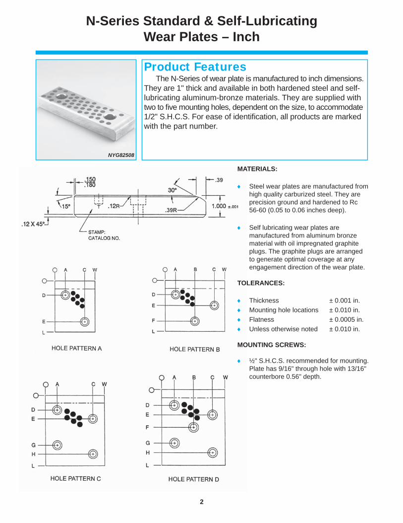
N-Series Standard & Self-Lubricating Wear Plates – Inch
MATERIALS:
Steel wear plates are manufactured from high quality carburized steel. They are precision ground and hardened to Rc 56-60 (0.05 to 0.06 inches deep).
Self lubricating wear plates are manufactured from aluminum bronze material with oil impregnated graphite plugs. The graphite plugs are arranged to generate optimal coverage at any engagement direction of the wear plate.
TOLERANCES:
Thickness ± 0.001 in. Mounting hole locations ± 0.010 in. Flatness ± 0.0005 in. Unless otherwise noted ± 0.010 in.
MOUNTING SCREWS:
½" S.H.C.S. recommended for mounting. Plate has 9/16" through hole with 13/16" counterbore 0.56" depth.
NYG82508
The N-Series of wear plate is manufactured to inch dimensions. They are 1" thick and available in both hardened steel and self- lubricating aluminum-bronze materials. They are supplied with two to fi ve mounting holes, dependent on the size, to accommodate 1/2" S.H.C.S. For ease of identifi cation, all products are marked with the part number.
Product Features

3
www.danly.com
Width Length Steel Self- Mounting Hole Pattern & Location W L Part Lubricating Hole Hole A B C D E F G H (in) (in) Number Part # Qty. Pattern (in) (in) (in) (in) (in) (in) (in) (in)
2.50 8.00 NSX82508 NYG82508 2 A 1.25 – 1.25 1.50 6.50 – – –
3.00 2.50 NSX83025 NYG83025 2 A 0.75 – 2.25 1.25 1.25 – – –
3.00 4.00 NSX8304 NYG8304 2 A 0.75 – 2.25 1.25 2.75 – – –
3.00 5.00 NSX8305 NYG8305 2 A 0.75 – 2.25 1.50 3.75 – – –
3.00 6.00 NSX8306 NYG8306 2 A 0.75 – 2.25 1.50 4.50 – – –
3.00 8.00 NSX8308 NYG8308 2 A 0.75 – 2.25 1.50 6.50 – – –
3.00 10.00 NSX8310 NYG8310 3 B 0.75 1.50 2.25 1.50 2.50 8.50 – –
3.00 12.00 NSX8312 NYG8312 3 B 0.75 1.50 2.25 1.50 2.50 10.50 – –
4.00 2.50 NSX84025 NYG84025 2 A 1.25 – 2.75 1.25 1.25 – – –
4.00 3.00 NSX8403 NYG8403 2 A 1.00 – 3.00 1.50 2.25 – – –
4.00 4.00 NSX8404 NYG8404 2 A 1.00 – 3.00 1.25 2.75 – – –
4.00 5.00 NSX8405 NYG8405 2 A 0.88 – 3.12 1.50 3.75 – – –
4.00 6.00 NSX8406 NYG8406 2 A 0.88 – 3.12 1.50 4.50 – – –
4.00 8.00 NSX8408 NYG8408 3 B 0.88 2.00 3.12 1.50 2.50 6.50 – –
4.00 10.00 NSX8410 NYG8410 3 B 0.88 2.00 3.12 1.50 2.50 8.50 – –
4.00 12.00 NSX8412 NYG8412 3 B 0.88 2.00 3.12 1.50 2.50 10.50 – –
5.00 2.50 NSX85025 NYG85025 2 A 1.25 – 3.75 1.25 1.25 – – –
5.00 4.00 NSX8504 NYG8504 2 A 1.00 – 4.00 1.50 2.75 – – –
5.00 5.00 NSX8505 NYG8505 2 A 1.00 – 4.00 1.50 3.75 – – –
5.00 6.00 NSX8506 NYG8506 2 A 1.00 – 4.00 1.50 4.50 – – –
5.00 8.00 NSX8508 NYG8508 3 B 1.00 2.50 4.00 1.50 2.50 6.50 – –
5.00 10.00 NSX8510 NYG8510 3 B 1.00 2.50 4.00 1.50 2.50 8.50 – –
5.00 12.00 NSX8512 NYG8512 4 C 1.00 – 4.00 1.50 2.50 – 9.50 10.50
6.00 4.00 NSX8604 NYG8604 3 B 1.00 3.00 5.00 1.25 2.25 2.75 – –
6.00 5.00 NSX8605 NYG8605 2 A 1.12 – 4.88 1.50 3.75 – – –
6.00 6.00 NSX8606 NYG8606 4 C 1.00 – 5.00 1.25 2.25 – 3.75 4.75
6.00 8.00 NSX8608 NYG8608 4 C 1.00 – 5.00 1.25 2.25 – 5.75 6.75
6.00 10.00 NSX8610 NYG8610 5 D 1.00 3.00 5.00 1.25 2.25 5.00 7.75 8.75
6.00 12.00 NSX8612 NYG8612 5 D 1.00 3.00 5.00 1.25 2.25 6.00 9.75 10.75
8.00 5.00 NSX8805 NYG8805 2 A 1.25 – 6.75 1.50 3.75 – – –
8.00 6.00 NSX8806 NYG8806 4 C 1.00 – 7.00 1.25 2.25 – 3.75 4.75
N-Series Standard & Self-Lubricating Wear Plates – Inch
5
6
4
8
3

4
www.danly.com
NAAMS Series W01, W02 & W03 Standard & Self-Lubricating Wear Plates – Metric
WYG20-50-100
The NAAMS Series of wear plate fully meets the North American Automotive Standard. They are 20mm thick and available in plain steel, steel with graphite plugs and aluminum-bronze with graphite plugs. The aluminum-bronze and steel with graphite plugs are self-lubricating products and do not require lubrication during production. All NAAMS wear plates are supplied with mounting holes to accommodate M12 S.H.C.S. For ease of identifi cation, all products are marked with the part number.
Product Features
NAAMS NAAMS
Code # Code #
(G)* (X)*
W 015010 W 025010
W 015015 W 025015
W 015020 W 025020
W 018010 W 028010
W 018015 W 028015
W 018020 W 028020
W 018025 W 028025
W 018031 W 028031
W 011025 W 021025
W 011031 W 021031
W 011050 W 021050
W 011080 W 021080
W 011010 W 021010
W 011015 W 021015
W 011020 W 021020
W 011231 W 021231
W 011280 W 021280
W 011210 W 021210
W 011215 W 021215
W 011220 W 021220
W 011225 W 021225
W 011610 W 021610
W 011615 W 021615
W 011620 W 021620
W 011625 W 021625
W 011631 W 021631
Steel Without Steel With Alum. Bronze With
Graphite Plugs Graphite Plugs Graphite Plugs Width Length
NAAMS NAAMS NAAMS W L
Part Number Code # Part Number Code # Part Number Code # (mm) (mm)
WSX20-50-100 W 025010 WSG20-50-100 W 015010 WYG20-50-100 W 035010 50 100
WSX20-50-150 W 025015 WSG20-50-150 W 015015 WYG20-50-150 W 035015 50 150
WSX20-50-200 W 025020 WSG20-50-200 W 015020 WYG20-50-200 W 035020 50 200
WSX20-80-100 W 028010 WSG20-80-100 W 018010 WYG20-80-100 W 038010 80 100
WSX20-80-150 W 028015 WSG20-80-150 W 018015 WYG20-80-150 W 038015 80 150
WSX20-80-200 W 028020 WSG20-80-200 W 018020 WYG20-80-200 W 038020 80 200
WSX20-80-250 W 028025 WSG20-80-250 W 018025 WYG20-80-250 W 038025 80 250
WSX20-80-315 W 028031 WSG20-80-315 W 018031 WYG20-80-315 W 038031 80 315
WSX20-100-50 W 021050 WSG20-100-50 W 011050 WYG20-100-50 W 031050 100 50
WSX20-100-80 W 021080 WSG20-100-80 W 011080 WYG20-100-80 W 031080 100 80
WSX20-100-100 W 021010 WSG20-100-100 W011010 WYG20-100-100 W 031010 100 100
WSX20-100-150 W 021015 WSG20-100-150 W 011015 WYG20-100-150 W 031015 100 150
WSX20-100-200 W 021020 WSG20-100-200 W 011020 WYG20-100-200 W 031020 100 200
WSX20-100-250 W 021025 WSG20-100-250 W 011025 WYG20-100-250 W 031025 100 250
WSX20-100-315 W 021031 WSG20-100-315 W 011031 WYG20-100-315 W 031031 100 315
WSX20-125-80 W 021280 WSG20-125-80 W 011280 WYG20-125-80 W 031280 125 80
WSX20-125-100 W 021210 WSG20-125-100 W 011210 WYG20-125-100 W 031210 125 100
WSX20-125-150 W 021215 WSG20-125-150 W 011215 WYG20-125-150 W 031215 125 150
WSX20-125-200 W 021220 WSG20-125-200 W 011220 WYG20-125-200 W 031220 125 200
WSX20-125-250 W 021225 WSG20-125-250 W 011225 WYG20-125-250 W 031225 125 250
WSX20-125-315 W 021231 WSG20-125-315 W 011231 WYG20-125-315 W 031231 125 315
WSX20-160-100 W 021610 WSG20-160-100 W 011610 WYG20-160-100 W 031610 160 100
WSX20-160-150 W 021615 WSG20-160-150 W 011615 WYG20-160-150 W 031615 160 150
WSX20-160-200 W 021620 WSG20-160-200 W 011620 WYG20-160-200 W 031620 160 200
WSX20-160-250 W 021625 WSG20-160-250 W 011625 WYG20-160-250 W 031625 160 250
WSX20-160-315 W 021631 WSG20-160-315 W 011631 WYG20-160-315 W 031631 160 315
160
80
125
100
50

5
www.danly.com
NAAMS Series W01, W02 & W03 Standard & Self-Lubricating Wear Plates – Metric
NAAMS Width Length
Code # W L Hole A B C D E F G
(Y)* (mm) (mm) Qty. Pattern (mm) (mm) (mm) (mm) (mm) (mm) (mm)
W 035010 50 100 2 A 25 – 25 30 – – 60
W 035015 50 150 2 A 25 – 25 30 – – 110
W 035020 50 200 2 A 25 – 25 40 – – 160
W 038010 80 100 2 A 20 – 60 30 – – 60
W 038015 80 150 2 A 20 – 60 30 – – 110
W 038020 80 200 2 A 20 – 60 40 – – 160
W 038025 80 250 2 A 20 – 60 40 – – 210
W 038031 80 315 3 B 20 40 60 40 – 250 275
W 031025 100 50 2 D 22 – 78 – 14 27 –
W 031031 100 80 2 D 22 – 78 – 30 50 –
W031050 100 100 2 A 22 – 78 30 – – 60
W 031080 100 150 2 A 22 – 78 30 – – 110
W 031010 100 200 3 B 22 50 78 40 – 135 160
W 031015 100 250 3 B 22 50 78 40 – 185 210
W 031020 100 315 3 B 22 50 78 40 – 250 275
W 031231 125 80 2 D 25 – 100 – 30 50 –
W 031280 125 100 2 A 25 – 100 30 – – 60
W 031210 125 150 2 A 25 – 100 30 – – 110
W 031215 125 200 3 B 25 62 100 40 – 135 160
W 031220 125 250 3 B 25 62 100 40 – 185 210
W 031225 125 315 4 C 25 – 100 40 65 250 275
W 031610 160 100 2 A 30 – 130 30 – – 60
W 031615 160 150 2 A 30 – 130 30 – – 110
W 031620 160 200 3 B 30 80 130 40 – 135 160
W 031625 160 250 4 C 30 – 130 40 65 185 210
W 031631 160 315 4 C 30 – 130 40 65 250 275
MATERIALS:
Steel wear plates are manufactured from high quality carburized steel.They are precision ground and hardened to Rc 56-60 (1.2 mm to 1.5 mm deep). They are available with or without graphite plugs.
Bronze wear plates are manufactured from aluminum bronze material with oil impregnated graphite plugs.
When ordered with graphite plugs,
the plugs cover 25-30% of the wear surface and are arranged to generate optimal coverage at any engagement direction of the wear plate.
TOLERANCES:
Thickness ± 0.025 mm Mounting hole
locations ± 0.25 mm Flatness ± 0.012 mm Unless otherwise
noted ± 0.25 mm
MOUNTING SCREWS:
M12 S.H.C.S. recommended. Plate has 13.5mm through hole with 20mm counterbore 13mm deep.
25
22
30
25
20
25
78
130
100
60
50
80
100
125
160
Mounting Hole Pattern & Location

6
www.danly.com
JIS Series Standard & Self-Lubricating Wear Plates – Metric
MATERIALS:
Steel wear plates are manufactured from high quality carburized steel. They are precision ground and hardened to Rc 56-60 (1.2 mm to 1.5 mm deep). They are available with or without graphite plugs.
Bronze wear plates are manufactured from aluminum bronze material with oil impregnated graphite plugs.
When ordered with graphite plugs, the plugs cover 25-30% of the wear surface and are arranged to generate optimal coverage at any engagement direction of the wear plate.
TOLERANCES:
Thickness ± 0.025 mm Mounting hole locations ± 0.25 mm Flatness ± 0.013 mm Unless otherwise noted ± 0.25 mm
MOUNTING SCREWS:
M10 S.H.C.S. recommended. Plate has 11mm through hole with 18mm counter-bore 12mm deep.
PATTERN A
PATTERN B
BYG20-58-75
The JIS Series of wear plate fully meets the Japanese Industrial Standard. They are 20mm thick and available in plain steel, steel with graphite plugs and aluminum-bronze with graphite plugs. The aluminum-bronze and steel with graphite plugs are self-lubricating products and do not require lubrication during production. They are supplied with two or four mounting holes to accommodate M10 S.H.C.S. For ease of identifi cation, all products are marked with the part number.
Product Features

7
www.danly.com
JIS Series Standard & Self-Lubricating Wear Plates – Metric
Width Length Steel Part # Steel Part # Alum. Bronze W L Without With Part # With Hole Hole A B C D (mm) (mm) Graphite Plugs Graphite Plugs Graphite Plugs Qty. Pattern (mm) (mm) (mm) (mm) 28 75 BSX20-28-75 BSG20-28-75 BYG20-28-75 2 A 15.0 60.0 28 100 BSX20-28-100 BSG20-28-100 BYG20-28-100 2 A 25.0 25.0 75.0 28 150 BSX20-28-150 BSG20-28-150 BYG20-28-150 2 25.0 125.0 38 75 BSX20-38-75 BSG20-38-75 BYG20-38-75 2 A 15.0 60.0 38 100 BSX20-38-100 BSG20-38-100 BYG20-38-100 2 A 25.0 75.0 38 150 BSX20-38-150 BSG20-38-150 BYG20-38-150 2 A 25.0 125.0 48 75 BSX20-48-75 BSG20-48-75 BYG20-48-75 2 A 15.0 60.0 48 100 BSX20-48-100 BSG20-48-100 BYG20-48-100 2 A 25.0 75.0 48 125 BSX20-48-125 BSG20-48-125 BYG20-48-125 2 A 25.0 100.0 48 150 BSX20-48-150 BSG20-48-150 BYG20-48-150 2 A 25.0 125.0 58 75 BSX20-58-75 BSG20-58-75 BYG20-58-75 2 A 15.0 60.0 58 100 BSX20-58-100 BSG20-58-100 BYG20-58-100 2 A 25.0 75.0 58 150 BSX20-58-150 BSG20-58-150 BYG20-58-150 2 A 25.0 125.0 75 75 BSX20-75-75 BSG20-75-75 BYG20-75-75 2 DIAG B 25.0 50.0 75 100 BSX20-75-100 BSG20-75-100 BYG20-75-100 2 DIAG B 25.0 75.0 75 125 BSX20-75-125 BSG20-75-125 BYG20-75-125 2 A 25.0 100.0 75 150 BSX20-75-150 BSG20-75-150 BYG20-75-150 2 A 25.0 125.0 75 200 BSX20-75-200 BSG20-75-200 BYG20-75-200 2 A 25.0 175.0 100 100 BSX20-100-100 BSG20-100-100 BYG20-100-100 4 B 25.0 75.0 100 125 BSX20-100-125 BSG20-100-125 BYG20-100-125 4 B 25.0 100.0 100 150 BSX20-100-150 BSG20-100-150 BYG20-100-150 4 B 25.0 125.0 100 200 BSX20-100-200 BSG20-100-200 BYG20-100-200 4 B 25.0 175.0 100 250 BSX20-100-250 BSG20-100-250 BYG20-100-250 4 B 25.0 225.0 125 150 BSX20-125-150 BSG20-125-150 BYG20-125-150 4 B 25.0 125.0 125 200 BSX20-125-200 BSG20-125-200 BYG20-125-200 4 B 25.0 175.0 125 250 BSX20-125-250 BSG20-125-250 BYG20-125-250 4 B 25.0 225.0 150 150 BSX20-150-150 BSG20-150-150 BYG20-150-150 4 B 25.0 125.0 150 200 BSX20-150-200 BSG20-150-200 BYG20-150-200 4 B 25.0 175.0 150 250 BSX20-150-250 BSG20-150-250 BYG20-150-250 4 B 25.0 225.0
38
58
100
150
125
75
48
28
2 A 19.0 –
2 A 24.0 –
2 A 29.0 –
2 A 37.5 –
4 B 25.0 75.0
4 B 37.5 87.5
4 B 25.0 125.0
2 A 14.0 –
B 25.0 50.02DIAGONAL

8
www.danly.com
Width Length Aluminum Bronze Steel Steel Mounting Hole Pattern & Location
W L w/Graphite Plugs w/Graphite Plugs Plain Hole Hole A B C D E
(mm) (mm) Part Number Part Number Part Number Qty. Pattern (mm) (mm) (mm) (mm) (mm)
50 80 VYG20-50-80 VSG20-50-80 VSX20-50-80 2 A-2 25 55 – 25 – 50 100 VYG20-50-100 VSG20-50-100 VSX20-50-100 2 A-2 25 75 – 25 – 50 125 VYG20-50-125 VSG20-50-125 VSX20-50-125 2 A-2 25 100 – 25 – 50 160 VYG20-50-160 VSG20-50-160 VSX20-50-160 2 A-2 25 135 – 25 – 50 200 VYG20-50-200 VSG20-50-200 VSX20-50-200 2 A-2 25 175 – 25 – 80 50 VYG20-80-50 VSG20-80-50 VSX20-80-50 2 B-2 25 – 25 – 55 80 80 VYG20-80-80 VSG20-80-80 VSX20-80-80 2 A-2 25 55 – 40 – 80 100 VYG20-80-100 VSG20-80-100 VSX20-80-100 2 A-2 25 75 – 40 – 80 125 VYG20-80-125 VSG20-80-125 VSX20-80-125 2 A-2 25 100 – 40 – 80 160 VYG20-80-160 VSG20-80-160 VSX20-80-160 2 A-2 25 135 – 40 – 80 200 VYG20-80-200 VSG20-80-200 VSX20-80-200 2 A-2 25 175 – 40 – 80 250 VYG20-80-250 VSG20-80-250 VSX20-80-250 2 A-2 40 210 – 40 – 80 315 VYG20-80-315 VSG20-80-315 VSX20-80-315 2 A-2 40 275 – 40 – 100 50 VYG20-100-50 VSG20-100-50 VSX20-100-50 2 B-2 25 – 25 – 75 100 80 VYG20-100-80 VSG20-100-80 VSX20-100-80 2 B-2 40 – 25 – 75 100 100 VYG20-100-100 VSG20-100-100 VSX20-100-100 2 A-2 25 75 – 50 – 100 125 VYG20-100-125 VSG20-100-125 VSX20-100-125 2 A-2 25 100 – 50 – 100 160 VYG20-100-160 VSG20-100-160 VSX20-100-160 2 A-2 25 135 – 50 – 100 200 VYG20-100-200 VSG20-100-200 VSX20-100-200 2 A-2 25 175 – 50 – 100 250 VYG20-100-250 VSG20-100-250 VSX20-100-250 2 A-2 40 210 – 50 – 100 315 VYG20-100-315 VSG20-100-315 VSX20-100-315 2 A-2 40 275 – 50 – 125 50 VYG20-125-50 VSG20-125-50 VSX20-125-50 2 B-2 25 – 25 – 100 125 80 VYG20-125-80 VSG20-125-80 VSX20-125-80 2 B-2 40 – 25 – 100 125 100 VYG20-125-100 VSG20-125-100 VSX20-125-100 3 B-3 25 75 25 62.5 100 125 125 VYG20-125-125 VSG20-125-125 VSX20-125-125 3 B-3 25 100 25 62.5 100 125 160 VYG20-125-160 VSG20-125-160 VSX20-125-160 3 B-3 25 135 25 62.5 100 125 200 VYG20-125-200 VSG20-125-200 VSX20-125-200 3 B-3 25 175 25 62.5 100 125 250 VYG20-125-250 VSG20-125-250 VSX20-125-250 3 B-3 40 210 25 62.5 100 315 VYG20-125-315 VSG20-125-315 VSX20-125-315 3 B-3 40 275 25 62.5 100 160 50 VYG20-160-50 VSG20-160-50 VSX20-160-50 2 B-2 25 – 25 – 135 160 80 VYG20-160-80 VSG20-160-80 VSX20-160-80 2 B-2 40 – 25 – 135 160 100 VYG20-160-100 VSG20-160-100 VSX20-160-100 3 B-3 25 75 25 80 135 160 125 VYG20-160-125 VSG20-160-125 VSX20-160-125 3 B-3 25 100 25 80 135 160 160 VYG20-160-160 VSG20-160-160 VSX20-160-160 3 B-3 25 135 25 80 135 160 200 VYG20-160-200 VSG20-160-200 VSX20-160-200 3 B-3 25 175 25 80 135 160 250 VYG20-160-250 VSG20-160-250 VSX20-160-250 4 C-4 40 210 25 – 135 160 315 VYG20-160-315 VSG20-160-315 VSX20-160-315 4 C-4 40 275 25 – 135
50
100
80
125
160
100
135
VDI/NAAMS STANDARDS
NAAMS Series W05, W06 & W07/VDI 3357Wear Plates – Metric
This wear plate conforms to the NAAMS Series W05, W06, W07 and VDI 3357 standards, up to 200mm. They are 20mm thick and available in aluminum-bronze material with graphite, steel with graphite and plain steel. They are also available inthe GM sizes in cast iron with graphite.
Product Features
VYG20-50-200

9
www.danly.com
NAAMS Series W05, W06 & W07/VDI 3357Wear Plates – Metric
MATERIALS:
Self-lubricating wear plates are manufactured from aluminum bronze or steel with graphite plugs. The plugs cover 20-25% of the wear surface.
Wear plates are also available in plain steel. Wear plates are also available in the GM
sizes in cast iron with graphite. See the cross reference sheet on pg. 11 for the GM part number.
TOLERANCES:
Thickness ± 0.00/ -0.02 mm Mounting hole locations ± 0.2 mm Flatness ± 0.013 mm Unless otherwise noted ± 0.25 mm
MOUNTING SCREWS:
M8 S.H.C.S. for part numbers VYG20-50-80 and VYG20-80-50.
M12 S.H.C.S. for all other part numbers.
Width Length Aluminum Bronze Steel Steel Mounting Hole Pattern & Location
W L w/Graphite Plugs w/Graphite Plugs Plain Hole Hole A B C D E
(mm) (mm) Part Number Part Number Part Number Qty. Pattern (mm) (mm) (mm) (mm) (mm)
100 250 WDX13-80-03100250Y* WDX13-80-03100250G* WDX13-80-03100250X* 2 A-2 25 225 – 50 – 100 250 90.20.65-100250Y* – 90.20.65-100250X* 4 C-4 25 225 25 – 75 100 315 WDX13-80-03100315Y* WDX13-80-03100315G* WDX13-80-03100315X* 2 A-2 25 290 – 50 – 125 200 90.20.65-125200* – 90.20.65-125200* 4 C-4 25 175 25 – 100 125 250 WDX13-80-03125250Y* WDX13-80-03125250G* WDX13-80-03125250X* 3 B-3 25 225 25 62.5 100 125 250 90.20.65-125250Y* – 90.20.65-125250X* 4 C-4 25 225 25 – 100 125 315 WDX13-80-03125315Y* WDX13-80-03125315G* WDX13-80-03125315X* 3 B-3 25 290 25 62.5 100 160 200 90.20.65-160200Y* – 90.20.65-160200G* 4 C-4 25 175 25 – 135 160 250 WDX13-80-03160250Y* WDX13-80-03160250G* WDX13-80-03160250X* 3 B-3 25 225 25 80 135 160 250 90.20.65-160250Y* – 90.20.65-160250X* 4 C-4 25 225 25 – 135 160 300 90.20.65-160300Y* – 90.20.65-160300X* 4 C-4 25 275 25 – 135 200 200 90.20.65-200200Y* – 90.20.65-200200X* 4 C-4 25 175 25 – 175 200 250 90.20.65-200250Y* – 90.20.65-200250X* 4 C-4 25 225 25 – 175 200 300 90.20.65-200300Y* – 90.20.65-200300X* 4 C-4 25 275 25 – 175
125
100
160
200
ADDITIONAL AUTOMOTIVE STANDARDS
PLEASE NOTE: These wear plates have hole patterns that differ from our standard VDI/NAAMS wear plates. They must
be ordered using the GM or Ford part number to receive the correct mounting hole locations.

10
www.danly.com
AutomotiveWear Plate Conversions
PLEASE NOTE:
The highlighted items (in grey) have different hole patterns than our existing wear plates. They do not convert to an IEM part number and must be ordered as highlighted.
Da
nly I
EM
NAAM
S W
07
Chry
sler
Ford
Par
t Num
ber
Gene
ral M
otor
s Da
nly I
EM
NAAM
S W
05
Ford
Wid
th
Leng
th
Part
Num
ber
Serie
s Num
ber
Part
Num
ber
Part
Num
ber
Part
Num
ber
Part
Num
ber
Serie
s Num
ber
Part
Num
ber
50
80
VY
G20-
50-8
0
VS
G20-
50-8
0
50
10
0 VY
G20-
50-1
00
W07
0510
19
-290
-320
4 W
DX13
8030
5010
0Y
90.20
.65-5
0100
Y VS
G20-
50-1
00
W05
0510
W
DX13
8030
5010
0G
50
125
VYG2
0-50
-125
W
0705
12
19-2
90-3
205
WDX
1380
3050
125Y
90
.20.65
-501
25Y
VSG2
0-50
-125
W
0505
12
WDX
1380
3050
125G
50
160
VYG2
0-50
-160
W
0705
16
19-2
90-3
206
WDX
1380
3050
160Y
90
.20.65
-501
60Y
VSG2
0-50
-160
W
0505
16
WDX
1380
3050
160G
50
200
VYG2
0-50
-200
W
0705
20
19-2
90-3
208
WDX
1380
3050
200Y
90
.20.65
-502
00Y
VSG2
0-50
-200
W
0505
20
WDX
1380
3050
200G
80
50
VYG2
0-80
-50
VSG2
0-80
-50
80
80
VYG2
0-80
-80
VSG2
0-80
-80
80
100
VYG2
0-80
-100
W
0708
10
19-2
90-3
304
WDX
1380
3080
100Y
90
.20.65
-801
00Y
VSG2
0-80
-100
W
0508
10
WDX
1380
3080
100G
80
125
VYG2
0-80
-125
W
0708
12
19-2
90-3
305
WDX
1380
3080
125Y
90
.20.65
-801
25Y
VSG2
0-80
-125
W
0508
12
WDX
1380
3080
125G
80
160
VYG2
0-80
-160
W
0708
16
19-2
90-3
306
WDX
1380
3080
160Y
90
.20.65
-801
60Y
VSG2
0-80
-160
W
0508
16
WDX
1380
3080
160G
80
20
0 VY
G20-
80-2
00
W07
0820
19
-290
-330
8 W
DX13
8030
8020
0Y
90.20
.65-8
0200
Y VS
G20-
80-2
00
W05
0820
W
DX13
8030
8020
0G
80
25
0 VY
G20-
80-2
50
19
-290
-331
0
VS
G20-
80-2
50
80
315
VYG2
0-80
-315
19-2
90-3
312
VSG2
0-80
-315
10
0 50
VY
G20-
100-
50
19
-290
-340
2
90.20
.65-1
0050
Y VS
G20-
100-
50
100
80
VYG2
0-10
0-80
W
0710
80
19-2
90-3
403
WDX
1380
3100
080Y
90
.20.65
-100
80Y
VSG2
0-10
0-80
W
0510
80
WDX
1380
3100
080G
100
100
VYG2
0-10
0-10
0 W
0710
10
19-2
90-3
404
WDX
1380
3100
100Y
90
.20.65
-100
100Y
VSG
20-1
00-1
00
W05
1010
W
DX13
8031
0010
0G
10
0 12
5 VY
G20-
100-
125
W07
1012
19
-290
-340
5 W
DX13
8031
0012
5Y
90.20
.65-1
0012
5Y V
SG20
-100
-125
W
0510
12
WDX
1380
3100
125G
10
0 16
0 VY
G20-
100-
160
W07
1016
19
-290
-340
6 W
DX13
8031
0016
0Y
90.20
.65-1
0016
0Y V
SG20
-100
-160
W
0510
16
WDX
1380
3100
160G
100
200
VYG2
0-10
0-20
0 W
0710
20
19-2
90-3
408
WDX
1380
3100
200Y
90
.20.65
-100
200Y
VSG
20-1
00-2
00
W05
1020
W
DX13
8031
0020
0G
10
0 25
0 VY
G20-
100-
250
19
-290
-341
0 W
DX13
8031
0025
0Y
90.20
.65-1
0025
0Y V
SG20
-100
-250
WDX
1380
3100
250G
10
0 31
5 VY
G20-
100-
315
19
-290
-341
2 W
DX13
8031
0031
5Y
VS
G20-
100-
315
W
DX13
8031
0031
5G
125
50
VYG2
0-12
5-50
VS
G20-
125-
50
125
80
VYG2
0-12
5-80
W
0712
08
19-2
90-3
503
WDX
1380
3125
080Y
90
.20.65
-125
80Y
VSG2
0-12
5-80
W
0512
08
WDX
1380
3125
080G
125
100
VYG2
0-12
5-10
0 W
0712
10
19-2
90-3
504
WDX
1380
3125
100Y
90
.20.65
-125
100Y
VSG
20-1
25-1
00
W05
1210
W
DX13
8031
2510
0G
12
5 12
5 VY
G20-
125-
125
W07
1212
19
-290
-350
5 W
DX13
8031
2512
5Y
90.20
.65-1
2512
5Y V
SG20
-125
-125
W
0512
12
WDX
1380
3125
125G
125
160
VYG2
0-12
5-16
0 W
0712
16
19-2
90-3
506
WDX
1380
3125
160Y
90
.20.65
-125
160Y
VSG
20-1
25-1
60
W05
1216
W
DX13
8031
2516
0G
12
5 20
0 VY
G20-
125-
200
W07
1220
19
-290
-350
8 W
DX13
8031
2520
0Y
90.20
.65-1
2520
0Y V
SG20
-125
-200
W
0512
20
WDX
1380
3125
200G
125
250
VYG2
0-12
5-25
0
19-2
90-3
510
WDX
1380
3125
250Y
90
.20.65
-125
250Y
VSG
20-1
25-2
50
W
DX13
8031
2525
0G
125
315
VYG2
0-12
5-31
5
19-2
90-3
512
WDX
1380
3125
315Y
VSG2
0-12
5-31
5
WDX
1380
3125
315G
16
0 50
VY
G20-
160-
50
VSG2
0-16
0-50
16
0 80
VY
G20-
160-
80
VSG2
0-16
0-80
16
0 10
0 VY
G20-
160-
100
W07
1610
19
-290
-360
4 W
DX13
8031
6010
0Y
90.20
.65-1
6010
0Y V
SG20
-160
-100
W
0516
10
WDX
1380
3160
100G
160
125
VYG2
0-16
0-12
5 W
0716
12
19-2
90-3
605
WDX
1380
3160
125Y
90
.20.65
-160
125Y
VSG
20-1
60-1
25
W05
1612
W
DX13
8031
6012
5G
16
0 16
0 VY
G20-
160-
160
W07
1616
19
-290
-360
6 W
DX13
8031
6016
0Y
90.20
.65-1
6016
0Y V
SG20
-160
-160
W
0516
16
WDX
1380
3160
160G
160
200
VYG2
0-16
0-20
0 W
0716
20
19-2
90-3
608
WDX
1380
3160
200Y
90
.20.65
-160
200Y
VSG
20-1
60-2
00
W
DX13
8031
6020
0G
16
0 25
0 VY
G20-
160-
250
19
-290
-361
0 W
DX13
8031
6025
0Y
90.20
.65-1
6025
0Y V
SG20
-160
-250
WDX
1380
3160
250G
16
0 30
0
90
.20.65
-160
300Y
16
0 31
5 VY
G20-
160-
315
19
-290
-361
2 W
DX13
8031
6031
5Y
VS
G20-
160-
315
W
DX13
8031
6031
5G
200
200
90.20
.65-2
0020
0Y
20
0 25
0
90
.20.65
-200
250Y
200
300
90.20
.65-2
0030
0Y
BR
ON
ZE W
ITH
GR
APH
ITE
PLU
GS
STEE
L W
ITH
GR
APH
ITE
PLU
GS
Dim
ensi
ons

11
www.danly.com
AutomotiveWear Plate Conversions
PLEASE NOTE:
The highlighted items (in grey) have different hole patterns than our existing wear plates. They do not convert to an IEM part number and must be ordered as highlighted.
Cast iron must be ordered using the GM part number.
Danl
y IEM
NA
AMS
W06
Ch
rysle
r Fo
rd P
art N
umbe
r Ge
nera
l Mot
ors
Gene
ral M
otor
s W
idth
Le
ngth
Pa
rt Nu
mbe
r Se
ries N
umbe
r Pa
rt Nu
mbe
r Pa
rt Nu
mbe
r Pa
rt Nu
mbe
r Pa
rt Nu
mbe
r
50
80
VS
X20-
50-8
0
50
10
0 VS
X20-
50-1
00
W06
0510
19
-290
-420
4 W
DX13
8030
5010
0X
90.20
.65-5
0100
X 90
.20.65
-501
00C
50
12
5 VS
X20-
50-1
25
W06
0512
19
-290
-420
5 W
DX13
8030
5012
5X
90.20
.65-5
0125
X 90
.20.65
-501
25C
50
16
0 VS
X20-
50-1
60
W06
0516
19
-290
-420
6 W
DX13
8030
5016
0X
90.20
.65-5
0160
X 90
.20.65
-501
60C
50
20
0 VS
X20-
50-2
00
W06
0520
19
-290
-420
8 W
DX13
8030
5020
0X
90.20
.65-5
0200
X 90
.20.65
-502
00C
80
50
VS
X20-
80-5
0
80
80
VS
X20-
80-8
0
80
10
0 VS
X20-
80-1
00
W06
0810
19
-290
-430
4 W
DX13
8030
8010
0X
90.20
.65-8
0100
X 90
.20.65
-801
00C
80
12
5 VS
X20-
80-1
25
W06
0812
19
-290
-430
5 W
DX13
8030
8012
5X
90.20
.65-8
0125
X 90
.20.65
-801
25C
80
16
0 VS
X20-
80-1
60
W06
0816
19
-290
-430
6 W
DX13
8030
8016
0X
90.20
.65-8
0160
X 90
.20.65
-801
60C
80
20
0 VS
X20-
80-2
00
W06
0820
19
-290
-430
8 W
DX13
8030
8020
0X
90.20
.65-8
0200
X 90
.20.65
-802
00C
80
25
0 VS
X20-
80-2
50
19
-290
-431
0
80
31
5 VS
X20-
80-3
15
19
-290
-431
2
10
0 50
VS
X20-
100-
50
19
-290
-440
2
90.20
.65-1
0050
X 90
.20.65
-100
50C
10
0 80
VS
X20-
100-
80
W06
1080
19
-290
-440
3 W
DX13
8031
0008
0X
90.20
.65-1
0080
X 90
.20.65
-100
80C
10
0 10
0 VS
X20-
100-
100
W06
1010
19
-290
-440
4 W
DX13
8031
0010
0X
90.20
.65-1
0010
0X
90.20
.65-1
0010
0C
100
125
VSX2
0-10
0-12
5 W
0610
12
19-2
90-4
405
WDX
1380
3100
125X
90
.20.65
-100
125X
90
.20.65
-100
125C
10
0 16
0 VS
X20-
100-
160
W06
1016
19
-290
-440
6 W
DX13
8031
0016
0X
90.20
.65-1
0016
0X
90.20
.65-1
0016
0C
100
200
VSX2
0-10
0-20
0 W
0610
20
19-2
90-4
408
WDX
1380
3100
200X
90
.20.65
-100
200X
90
.20.65
-100
200C
10
0 25
0 VS
X20-
100-
250
19
-290
-441
0 W
DX13
8031
0025
0X
90.20
.65-1
0025
0X
90.20
.65-1
0025
0C
100
315
VSX2
0-10
0-31
5
19-2
90-4
412
WDX
1380
3100
315X
125
50
VSX2
0-12
5-50
12
5 80
VS
X20-
125-
80
W06
1208
19
-290
-450
3 W
DX13
8031
2508
0X
90.20
.65-1
2580
X 90
.20.65
-125
80C
12
5 10
0 VS
X20-
125-
100
W06
1210
19
-290
-450
4 W
DX13
8031
2510
0X
90.20
.65-1
2510
0X
90.20
.65-1
2510
0C
125
125
VSX2
0-12
5-12
5 W
0612
12
19-2
90-4
505
WDX
1380
3125
125X
90
.20.65
-125
125X
90
.20.65
-125
125C
12
5 16
0 VS
X20-
125-
160
W06
1216
19
-290
-450
6 W
DX13
8031
2516
0X
90.20
.65-1
2516
0X
90.20
.65-1
2516
0C
125
200
VSX2
0-12
5-20
0 W
0612
20
19-2
90-4
508
WDX
1380
3125
200X
90
.20.65
-125
200X
90
.20.65
-125
200C
12
5 25
0 VS
X20-
125-
250
19
-290
-451
0 W
DX13
8031
2525
0X
90.20
.65-1
2525
0X
90.20
.65-1
2525
0C
125
315
VSX2
0-12
5-31
5
19-2
90-4
512
WDX
1380
3125
315X
160
50
VSX2
0-16
0-50
16
0 80
VS
X20-
160-
80
160
100
VSX2
0-16
0-10
0 W
0616
10
19-2
90-4
604
WDX
1380
3160
100X
90
.20.65
-160
100X
90
.20.65
-160
100C
16
0 12
5 VS
X20-
160-
125
W06
1612
19
-290
-460
5 W
DX13
8031
6012
5X
90.20
.65-1
6012
5X
90.20
.65-1
6012
5C
160
160
VSX2
0-16
0-16
0 W
0616
16
19-2
90-4
606
WDX
1380
3160
160X
90
.20.65
-160
160X
90
.20.65
-160
160C
16
0 20
0 VS
X20-
160-
200
W06
1620
19
-290
-460
8 W
DX13
8031
6020
0X
90.20
.65-1
6020
0X
90.20
.65-1
6020
0C
160
250
VSX2
0-16
0-25
0
19-2
90-4
610
WDX
1380
3160
250X
90
.20.65
-160
250X
90
.20.65
-160
250C
16
0 30
0
90
.20.65
-160
300X
90
.20.65
-160
300C
16
0 31
5 VS
X20-
160-
315
19
-290
-461
2 W
DX13
8031
6031
5X
20
0 20
0
90
.20.65
-200
200X
90
.20.65
-200
200C
20
0 25
0
90
.20.65
-200
250X
90
.20.65
-200
250C
20
0 30
0
90
.20.65
-200
300X
90
.20.65
-200
300C
PLA
IN S
TEEL
Dim
ensi
ons
CA
ST IR
ON
w/G
RA
PHIT
E PL
UG
S
12
www.danly.com
PATTERN A PATTERN B
PATTERN C
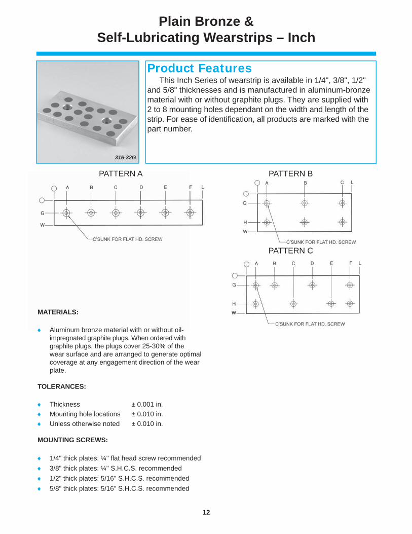
Plain Bronze & Self-Lubricating Wearstrips – Inch
MATERIALS:
Aluminum bronze material with or without oil-impregnated graphite plugs. When ordered with graphite plugs, the plugs cover 25-30% of the wear surface and are arranged to generate optimal coverage at any engagement direction of the wear plate.
TOLERANCES:
Thickness ± 0.001 in. Mounting hole locations ± 0.010 in. Unless otherwise noted ± 0.010 in.
MOUNTING SCREWS:
1/4" thick plates: ¼" fl at head screw recommended 3/8" thick plates: ¼" S.H.C.S. recommended 1/2" thick plates: 5/16" S.H.C.S. recommended 5/8" thick plates: 5/16" S.H.C.S. recommended
316-32G
This Inch Series of wearstrip is available in 1/4", 3/8", 1/2" and 5/8" thicknesses and is manufactured in aluminum-bronze material with or without graphite plugs. They are supplied with 2 to 8 mounting holes dependant on the width and length of the strip. For ease of identifi cation, all products are marked with the part number.
Product Features
13
www.danly.com
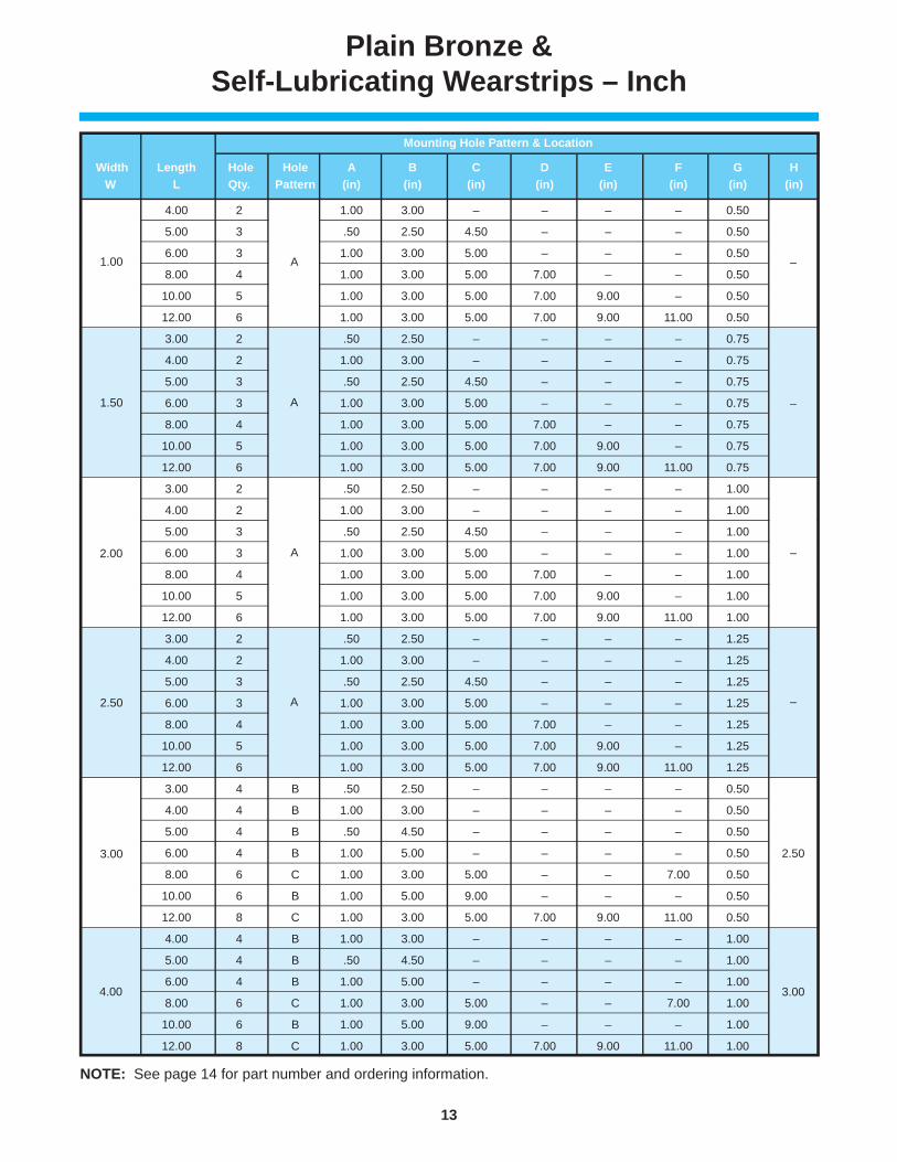
Plain Bronze & Self-Lubricating Wearstrips – Inch
Mounting Hole Pattern & Location
Width Length Hole Hole A B C D E F G H
W L Qty. Pattern (in) (in) (in) (in) (in) (in) (in) (in)
1.00 4.00 2 A 1.00 3.00 – – – – 0.50 –
1.00 5.00 3 A .50 2.50 4.50 – – – 0.50 –
1.00 6.00 3 A 1.00 3.00 5.00 – – – 0.50 –
1.00 8.00 4 A 1.00 3.00 5.00 7.00 – – 0.50 –
1.00 10.00 5 A 1.00 3.00 5.00 7.00 9.00 – 0.50 –
1.00 12.00 6 A 1.00 3.00 5.00 7.00 9.00 11.00 0.50 –
1.50 3.00 2 A .50 2.50 – – – – 0.75 –
1.50 4.00 2 A 1.00 3.00 – – – – 0.75 –
1.50 5.00 3 A .50 2.50 4.50 – – – 0.75 –
1.50 6.00 3 A 1.00 3.00 5.00 – – – 0.75 –
1.50 8.00 4 A 1.00 3.00 5.00 7.00 – – 0.75 –
1.50 10.00 5 A 1.00 3.00 5.00 7.00 9.00 – 0.75 –
1.50 12.00 6 A 1.00 3.00 5.00 7.00 9.00 11.00 0.75 –
2.00 3.00 2 A .50 2.50 – – – – 1.00 –
2.00 4.00 2 A 1.00 3.00 – – – – 1.00 –
2.00 5.00 3 A .50 2.50 4.50 – – – 1.00 –
2.00 6.00 3 A 1.00 3.00 5.00 – – – 1.00
2.00 8.00 4 A 1.00 3.00 5.00 7.00 – – 1.00 –
2.00 10.00 5 A 1.00 3.00 5.00 7.00 9.00 – 1.00 –
2.00 12.00 6 A 1.00 3.00 5.00 7.00 9.00 11.00 1.00 –
2.50 3.00 2 A .50 2.50 – – – – 1.25 –
2.50 4.00 2 A 1.00 3.00 – – – – 1.25 –
2.50 5.00 3 A .50 2.50 4.50 – – – 1.25 –
2.50 6.00 3 A 1.00 3.00 5.00 – – – 1.25 –
2.50 8.00 4 A 1.00 3.00 5.00 7.00 – – 1.25 –
2.50 10.00 5 A 1.00 3.00 5.00 7.00 9.00 – 1.25 –
2.50 12.00 6 A 1.00 3.00 5.00 7.00 9.00 11.00 1.25 –
3.00 3.00 4 B .50 2.50 – – – – 0.50 2.50
3.00 4.00 4 B 1.00 3.00 – – – – 0.50 2.50
3.00 5.00 4 B .50 4.50 – – – – 0.50 2.50
3.00 6.00 4 B 1.00 5.00 – – – – 0.50 2.50
3.00 8.00 6 C 1.00 3.00 5.00 – – 7.00 0.50 2.50
3.00 10.00 6 B 1.00 5.00 9.00 – – – 0.50 2.50
3.00 12.00 8 C 1.00 3.00 5.00 7.00 9.00 11.00 0.50 2.50
4.00 4.00 4 B 1.00 3.00 – – – – 1.00 3.00
4.00 5.00 4 B .50 4.50 – – – – 1.00 3.00
4.00 6.00 4 B 1.00 5.00 – – – – 1.00 3.00
4.00 8.00 6 C 1.00 3.00 5.00 – – 7.00 1.00 3.00
4.00 10.00 6 B 1.00 5.00 9.00 – – – 1.00 3.00
4.00 12.00 8 C 1.00 3.00 5.00 7.00 9.00 11.00 1.00 3.00
1.00
2.00
3.00
2.50
1.50 A
A
A
A
4.00
NOTE: See page 14 for part number and ordering information.
3.00
–
–
–
–
2.50

14
www.danly.com
Plain Bronze & Self-Lubricating Wearstrips – Inch
Width Length With Without W L Graphite Graphite (in) (in) Plugs Part # Plugs Part # 1.00 4.00 38-32G 38-32 1.00 5.00 38-40G 38-40 1.00 6.00 38-48G 38-48 1.00 8.00 38-64G 38-64 1.00 10.00 38-80G 38-80 1.00 12.00 38-96G 38-96 1.50 4.00 312-32G 312-32 1.50 5.00 312-40G 312-40 1.50 6.00 312-48G 312-48 1.50 8.00 312-64G 312-64 1.50 10.00 312-80G 312-80 1.50 12.00 312-96G 312-96 2.00 4.00 316-32G 316-32 2.00 5.00 316-40G 316-40 2.00 6.00 316-48G 316-48 2.00 8.00 316-64G 316-64 2.00 10.00 316-80G 316-80 2.00 12.00 316-96G 316-96 2.50 4.00 320-32G 320-32 2.50 5.00 320-40G 320-40 2.50 6.00 320-48G 320-48 2.50 8.00 320-64G 320-64 2.50 10.00 320-80G 320-80 2.50 12.00 320-96G 320-96 4.00 324-32G 324-32 3.00 5.00 324-40G 324-40 3.00 6.00 324-48G 324-48 3.00 8.00 324-64G 324-64 3.00 10.00 324-80G 324-80 3.00 12.00 324-96G 324-96 4.00 4.00 332-32G 332-32 4.00 5.00 332-40G 332-40 4.00 6.00 332-48G 332-48 4.00 8.00 332-64G 332-64 4.00 10.00 332-80G 332-80 4.00 12.00 332-96G 332-96 1.50 3.00 512-24G 512-24 1.50 4.00 512-32G 512-32 1.50 5.00 512-40G 512-40 1.50 6.00 512-48G 512-48 1.50 8.00 512-64G 512-64 1.50 10.00 512-80G 512-80 1.50 12.00 512-96G 512-96 2.00 3.00 516-24G 516-24 2.00 4.00 516-32G 516-32 2.00 5.00 516-40G 516-40 2.00 6.00 516-48G 516-48 2.00 8.00 516-64G 516-64 2.00 10.00 516-80G 516-80 2.00 12.00 516-96G 516-96 2.50 3.00 520-24G 520-24 2.50 4.00 520-32G 520-32 2.50 5.00 520-40G 520-40 2.50 6.00 520-48G 520-48 2.50 8.00 520-64G 520-64 2.50 10.00 520-80G 520-80 2.50 12.00 520-96G 520-96 3.00 3.00 524-24G 524-24 3.00 4.00 524-32G 524-32 3.00 5.00 524-40G 524-40 3.00 6.00 524-48G 524-48 3.00 8.00 524-64G 524-64 3.00 10.00 524-80G 524-80 3.00 12.00 524-96G 524-96 4.00 4.00 532-32G 532-32 4.00 5.00 532-40G 532-40 4.00 6.00 532-48G 532-48 4.00 8.00 532-64G 532-64 4.00 10.00 532-80G 532-80 4.00 12.00 532-96G 532-96
3/8"
Thi
ck W
ear S
trip
s5/
8" T
hick
Wea
r Str
ips
4.00
2.50
1.50
3.00
2.00
1.00
1.50
2.50
4.00
2.00
3.00
Width Length With Without W L Graphite Graphite (in) (in) Plugs Part # Plugs Part # 1.00 4.00 28-32G 28-32 1.00 5.00 28-40G 28-40 1.00 6.00 28-48G 28-48 1.00 8.00 28-64G 28-64 1.00 10.00 28-80G 28-80 1.00 12.00 28-96G 28-96 1.50 4.00 212-32G 212-32 1.50 5.00 212-40G 212-40 1.50 6.00 212-48G 212-48 1.50 8.00 212-64G 212-64 1.50 10.00 212-80G 212-80 1.50 12.00 212-96G 212-96 2.00 4.00 216-32G 216-32 2.00 5.00 216-40G 216-40 2.00 6.00 216-48G 216-48 2.00 8.00 216-64G 216-64 2.00 10.00 216-80G 216-80 2.00 12.00 216-96G 216-96 2.50 4.00 220-32G 220-32 2.50 5.00 220-40G 220-40 2.50 6.00 220-48G 220-48 2.50 8.00 220-64G 220-64 2.50 10.00 220-80G 220-80 2.50 12.00 220-96G 220-96 3.00 4.00 224-32G 224-32 3.00 5.00 224-40G 224-40 3.00 6.00 224-48G 224-48 3.00 8.00 224-64G 224-64 3.00 10.00 224-80G 224-80 3.00 12.00 224-96G 224-96 4.00 4.00 232-32G 232-32 4.00 5.00 232-40G 232-40 4.00 6.00 232-48G 232-48 4.00 8.00 232-64G 232-64 4.00 10.00 232-80G 232-80 4.00 12.00 232-96G 232-96 1.50 3.00 412-24G 412-24 1.50 4.00 412-32G 412-32 1.50 5.00 412-40G 412-40 1.50 6.00 412-48G 412-48 1.50 8.00 412-64G 412-64 1.50 10.00 412-80G 412-80 1.50 12.00 412-96G 412-96 2.00 3.00 416-24G 416-24 2.00 4.00 416-32G 416-32 2.00 5.00 416-40G 416-40 2.00 6.00 416-48G 416-48 2.00 8.00 416-64G 416-64 2.00 10.00 416-80G 416-80 2.00 12.00 416-96G 416-96 2.50 3.00 420-24G 420-24 2.50 4.00 420-32G 420-32 2.50 5.00 420-40G 420-40 2.50 6.00 420-48G 420-48 2.50 8.00 420-64G 420-64 2.50 10.00 420-80G 420-80 2.50 12.00 420-96G 420-96 3.00 3.00 424-24G 424-24 3.00 4.00 424-32G 424-32 3.00 5.00 424-40G 424-40 3.00 6.00 424-48G 424-48 3.00 8.00 424-64G 424-64 3.00 10.00 424-80G 424-80 3.00 12.00 424-96G 424-96 4.00 4.00 432-32G 432-32 4.00 5.00 432-40G 432-40 4.00 6.00 432-48G 432-48 4.00 8.00 432-64G 432-64 4.00 10.00 432-80G 432-80 4.00 12.00 432-96G 432-96
1.00
2.00
3.00
1.50
2.50
4.00
3.00
2.00
4.00
2.50
1.50
1/4"
Thi
ck W
ear S
trip
s1/
2" T
hick
Wea
r Str
ips

15
www.danly.com
Self-Lubricating Wearstrip Ways – Inch
MATERIALS:
Aluminum bronze material with oil impregnated graphite plugs. The plugs cover 25-30% of the wear surface and are arranged to generate optimal coverage at any engagement direction of the wearstrip.
TOLERANCES:
Thickness ± 0.001 in. Unless otherwise noted ± 0.010 in.
MOUNTING SCREWS:
Normal procedure is to use the graphite plug location for screw hole location.
1/4" fl athead or socket head screw (maximum) recommended for 3/8" thick strips.
3/8" fl athead or socket head screw (maximum) recommended for 1/2", 5/8" and 3/4" inch thick strips.
Plug Part Thickness Width Diameter Number T (in) W (in) (in)312-320NG 1.50 5/16316-320NG 2.00 3/8 320-320NG 2.50 3/8 324-320NG 3.00 1/2 412-320NG 1.50 5/16416-320NG 2.00 3/8 420-320NG 2.50 3/8 424-320NG 3.00 1/2 432-320NG 4.00 1/2 516-320NG 2.00 3/8 524-320NG 3.00 1/2 532-320NG 4.00 1/2 616-320NG 2.00 3/8 624-320NG 3.00 1/2 632-320NG 4.00 1/2 640-320NG 5.00 1/2
0.500
0.750
0.375
0.625
316-320NG
This Inch Series of wearstrips is sold in 40-inch lengths without mounting holes. They are designed to be cut to length and drilled for mounting as required. They are manufactured from self-lubricated aluminum-bronze material with oil-impregnated graphite plugs. They are available in 3/8", 1/2", 5/8" and 3/4" thicknesses. For ease of identifi cation, all products are marked with the part number.
Product Features

16
www.danly.com
Plain Bronze & Self-Lubricating Wearstrips – Inch
MATERIALS:
Aluminum bronze material with or without oil impregnated graphite plugs. When ordered with graphite plugs, the plugs cover 25-30% of the wear surface and are arranged to generate optimal coverage at any engagement direction of the wearstrip.
TOLERANCES:
Thickness ± 0.001 in. Unless otherwise noted ± 0.010 in.
MOUNTING SCREWS:
Mounting holes must be drilled. Recommend using plug locations for drilling mounting holes.
212-32NG
This Inch Series of wearstrip is available in 1/4", 3/8", 1/2" and 5/8" thicknesses and is manufactured in aluminum-bronze material with or without graphite plugs. They are supplied without mounting holes. For ease of identifi cation, all products are marked with the part number.
Product Features
T

17
www.danly.com
Plain Bronze & Self-Lubricating Wearstrips – Inch
Width Length With Without W L Graphite Graphite (in) (in) Plugs Part # Plugs Part # 1 4 38-32NG 38-32N 1 5 38-40NG 38-40N 1 6 38-48NG 38-48N 1 8 38-64NG 38-64N 1 10 38-80NG 38-80N 1 12 38-96NG 38-96N 1.5 4 312-32NG 312-32N 1.5 5 312-40NG 312-40N 1.5 6 312-48NG 312-48N 1.5 8 312-64NG 312-64N 1.5 10 312-80NG 312-80N 1.5 12 312-96NG 312-96N 2 4 316-32NG 316-32N 2 5 316-40NG 316-40N 2 6 316-48NG 316-48N 2 8 316-64NG 316-64N 2 10 316-80NG 316-80N 2 12 316-96NG 316-96N 2.5 4 320-32NG 320-32N 2.5 5 320-40NG 320-40N 2.5 6 320-48NG 320-48N 2.5 8 320-64NG 320-64N 2.5 10 320-80NG 320-80N 2.5 12 320-96NG 320-96N 3 4 324-32NG 324-32N 3 5 324-40NG 324-40N 3 6 324-48NG 324-48N 3 8 324-64NG 324-64N 3 10 324-80NG 324-80N 3 12 324-96NG 324-96N 4 4 332-32NG 332-32N 4 5 332-40NG 332-40N 4 6 332-48NG 332-48N 4 8 332-64NG 332-64N 4 10 332-80NG 332-80N 12 332-96NG 332-96N 1.5 3 512-24NG 512-24N 1.5 4 512-32NG 512-32N 1.5 5 512-40NG 512-40N 1.5 6 512-48NG 512-48N 1.5 8 512-64NG 512-64N 1.5 10 512-80NG 512-80N 1.5 12 512-96NG 512-96N 3 516-24NG 516-24N 2 4 516-32NG 516-32N 2 5 516-40NG 516-40N 2 6 516-48NG 516-48N 2 8 516-64NG 516-64N 2 10 516-80NG 516-80N 2 12 516-96NG 516-96N 3 520-24NG 520-24N 2.5 4 520-32NG 520-32N 2.5 5 520-40NG 520-40N 2.5 6 520-48NG 520-48N 2.5 8 520-64NG 520-64N 2.5 10 520-80NG 520-80N 2.5 12 520-96NG 520-96N 3 524-24NG 524-24N 3 4 524-32NG 524-32N 3 5 524-40NG 524-40N 3 6 524-48NG 524-48N 3 8 524-64NG 524-64N 3 10 524-80NG 524-80N 3 12 524-96NG 524-96N 4 4 532-32NG 532-32N 4 5 532-40NG 532-40N 4 6 532-48NG 532-48N 4 8 532-64NG 532-64N 4 10 532-80NG 532-80N 4 12 532-96NG 532-96N
3/8"
Thi
ck W
ear S
trip
s5/
8" T
hick
Wea
r Str
ips
2.5
2
3
1.5
2.5
4
3
2
1
1.5
4
Width Length With Without W L Graphite Graphite (in) (in) Plugs Part # Plugs Part # 1 4 28-32NG 28-32N 1 5 28-40NG 28-40N 1 6 28-48NG 28-48N 1 8 28-64NG 28-64N 1 10 28-80NG 28-80N 1 12 28-96NG 28-96N 1.5 4 212-32NG 212-32N 1.5 5 212-40NG 212-40N 1.5 6 212-48NG 212-48N 1.5 8 212-64NG 212-64N 1.5 10 212-80NG 212-80N 1.5 12 212-96NG 212-96N 2 4 216-32NG 216-32N 2 5 216-40NG 216-40N 2 6 216-48NG 216-48N 2 8 216-64NG 216-64N 2 10 216-80NG 216-80N 12 216-96NG 216-96N 4 220-32NG 220-32N 2.5 5 220-40NG 220-40N 2.5 6 220-48NG 220-48N 2.5 8 220-64NG 220-64N 2.5 10 220-80NG 220-80N 12 220-96NG 220-96N 3 4 224-32NG 224-32N 3 5 224-40NG 224-40N 3 6 224-48NG 224-48N 3 8 224-64NG 224-64N 3 10 224-80NG 224-80N 12 224-96NG 224-96N 4 4 232-32NG 232-32N 4 5 232-40NG 232-40N 4 6 232-48NG 232-48N 4 8 232-64NG 232-64N 4 10 232-80NG 232-80N 4 12 232-96NG 232-96N 1.5 3 412-24NG 412-24N 1.5 4 412-32NG 412-32N 1.5 5 412-40NG 412-40N 1.5 6 412-48NG 412-48N 1.5 8 412-64NG 412-64N 1.5 10 412-80NG 412-80N 1.5 12 412-96NG 412-96N 2 3 416-24NG 416-24N 2 4 416-32NG 416-32N 2 5 416-40NG 416-40N 2 6 416-48NG 416-48N 2 8 416-64NG 416-64N 2 10 416-80NG 416-80N 2 12 416-96NG 416-96N 3 420-24NG 420-24N 2.5 4 420-32NG 420-32N 2.5 5 420-40NG 420-40N 2.5 6 420-48NG 420-48N 2.5 8 420-64NG 420-64N 2.5 10 420-80NG 420-80N 2.5 12 420-96NG 420-96N 3 424-24NG 424-24N 3 4 424-32NG 424-32N 3 5 424-40NG 424-40N 3 6 424-48NG 424-48N 3 8 424-64NG 424-64N 3 10 424-80NG 424-80N 3 12 424-96NG 424-96N 4 432-32NG 432-32N 4 5 432-40NG 432-40N 4 6 432-48NG 432-48N 4 8 432-64NG 432-64N 4 10 432-80NG 432-80N 4 12 432-96NG 432-96N
1/4"
Thi
ck W
ear S
trip
s1/
2" T
hick
Wea
r Str
ips
1.5
2.5
4
3
2
1
3
2
1.5
2.5
4
18
www.danly.com
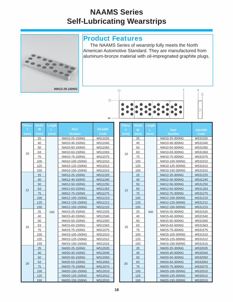
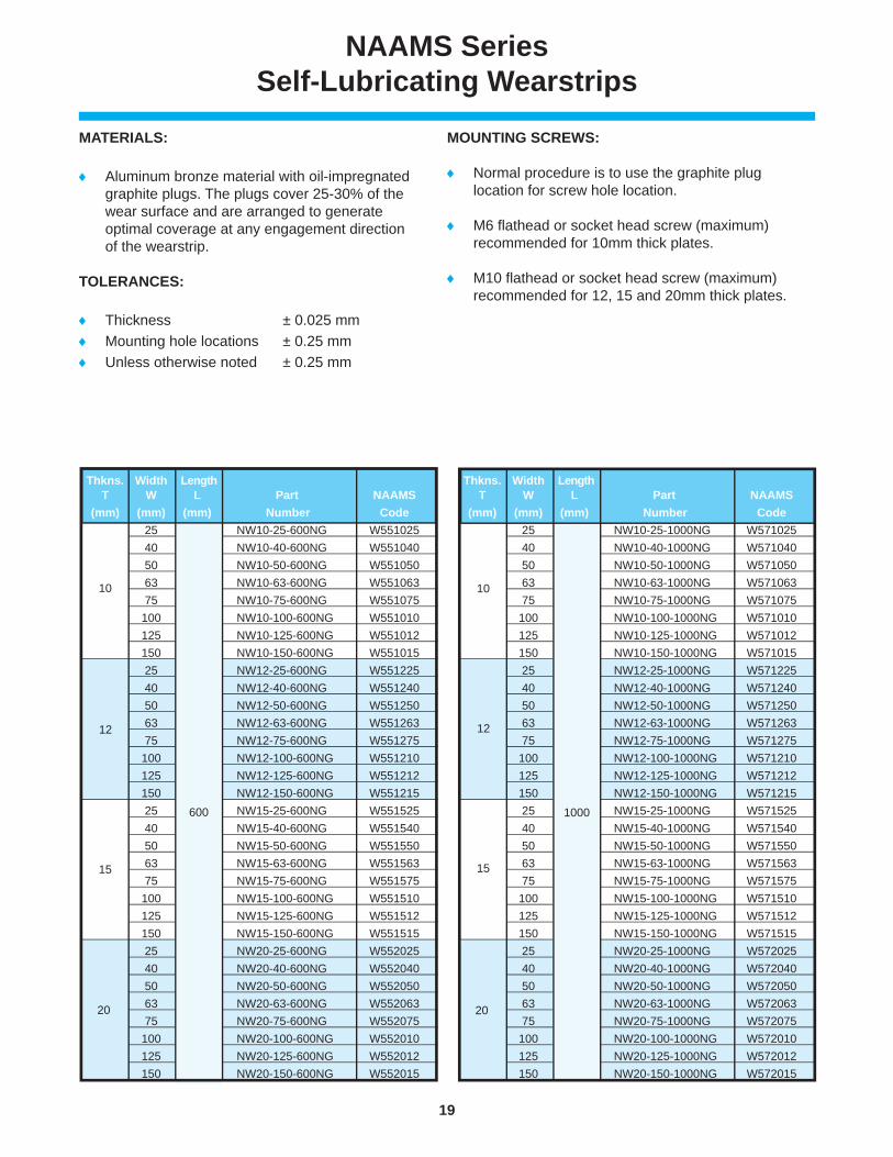
NAAMS Series Self-Lubricating Wearstrips
Thkns. Width Length T W L Part NAAMS (mm) (mm) (mm) Number Code 10 25 300 NW10-25-300NG W531025 40 NW10-40-300NG W531040 50 NW10-50-300NG W531050 63 NW10-63-300NG W531063 75 NW10-75-300NG W531075 100 NW10-100-300NG W531010 125 NW10-125-300NG W531012 150 NW10-150-300NG W531015 12 25 NW12-25-300NG W531225 40 NW12-40-300NG W531240 50 NW12-50-300NG W531250 63 NW12-63-300NG W531263 75 NW12-75-300NG W531275 100 NW12-100-300NG W531210 125 NW12-125-300NG W531212 150 NW12-150-300NG W531215 15 25 NW15-25-300NG W531525 40 NW15-40-300NG W531540 50 NW15-50-300NG W531550 63 NW15-63-300NG W531563 75 NW15-75-300NG W531575 100 NW15-100-300NG W531510 125 NW15-125-300NG W531512 150 NW15-150-300NG W531515 20 25 NW20-25-300NG W532025 40 NW20-40-300NG W532040 50 NW20-50-300NG W532050 63 NW20-63-300NG W532063 75 NW20-75-300NG W532075 100 NW20-100-300NG W532010 125 NW20-125-300NG W532012 150 NW20-150-300NG W532015
20
300
10
12
15
Thkns. Width Length T W L Part NAAMS (mm) (mm) (mm) Number Code 25 NW10-25-150NG W511025 40 NW10-40-150NG W511040 50 NW10-50-150NG W511050 63 NW10-63-150NG W511063 75 NW10-75-150NG W511075 100 NW10-100-150NG W511010 125 NW10-125-150NG W511012 150 NW10-150-150NG W511015 12 25 NW12-25-150NG W511225 40 NW12-40-150NG W511240 50 NW12-50-150NG W511250 63 NW12-63-150NG W511263 75 NW12-75-150NG W511275 100 NW12-100-150NG W511210 125 NW12-125-150NG W511212 150 NW12-150-150NG W51121515 25 NW15-25-150NG W511525 40 NW15-40-150NG W511540 50 NW15-50-150NG W511550 63 NW15-63-150NG W511563 75 NW15-75-150NG W511575 100 NW15-100-150NG W511510 125 NW15-125-150NG W511512 150 NW15-150-150NG W511515 20 25 NW20-25-150NG W512025 40 NW20-40-150NG W512040 50 NW20-50-150NG W512050 63 NW20-63-150NG W512063 75 NW20-75-150NG W512075 100 NW20-100-150NG W512010 125 NW20-125-150NG W512012 150 NW20-150-150NG W512015
10
12
15
NW12-25-150NG
The NAAMS Series of wearstrip fully meets the NorthAmerican Automotive Standard. They are manufactured from aluminum-bronze material with oil-impregnated graphite plugs.
Product Features
20
150
19
www.danly.com
NAAMS Series Self-Lubricating Wearstrips
MATERIALS:
Aluminum bronze material with oil-impregnated graphite plugs. The plugs cover 25-30% of the wear surface and are arranged to generate optimal coverage at any engagement direction of the wearstrip.
TOLERANCES:
Thickness ± 0.025 mm Mounting hole locations ± 0.25 mm Unless otherwise noted ± 0.25 mm
MOUNTING SCREWS:
Normal procedure is to use the graphite plug location for screw hole location.
M6 fl athead or socket head screw (maximum) recommended for 10mm thick plates.
M10 fl athead or socket head screw (maximum) recommended for 12, 15 and 20mm thick plates.
Thkns. Width Length T W L Part NAAMS (mm) (mm) (mm) Number Code 25 NW10-25-600NG W551025 40 NW10-40-600NG W551040 50 NW10-50-600NG W551050 63 NW10-63-600NG W551063 75 NW10-75-600NG W551075 100 NW10-100-600NG W551010 125 NW10-125-600NG W551012 150 NW10-150-600NG W551015 12 25 NW12-25-600NG W551225 40 NW12-40-600NG W551240 50 NW12-50-600NG W551250 63 NW12-63-600NG W551263 75 NW12-75-600NG W551275 100 NW12-100-600NG W551210 125 NW12-125-600NG W551212 150 NW12-150-600NG W551215 15 25 NW15-25-600NG W551525 40 NW15-40-600NG W551540 50 NW15-50-600NG W551550 63 NW15-63-600NG W551563 75 NW15-75-600NG W551575 100 NW15-100-600NG W551510 125 NW15-125-600NG W551512 150 NW15-150-600NG W551515 20 25 NW20-25-600NG W552025 40 NW20-40-600NG W552040 50 NW20-50-600NG W552050 63 NW20-63-600NG W552063 75 NW20-75-600NG W552075 100 NW20-100-600NG W552010 125 NW20-125-600NG W552012 150 NW20-150-600NG W552015
600
15
10
12
20
Thkns. Width Length T W L Part NAAMS (mm) (mm) (mm) Number Code Thk10 25 1000 NW10-25-1000NG W571025 40 NW10-40-1000NG W571040 50 NW10-50-1000NG W571050 63 NW10-63-1000NG W571063 75 NW10-75-1000NG W571075 100 NW10-100-1000NG W571010 125 NW10-125-1000NG W571012 150 NW10-150-1000NG W571015 12 25 NW12-25-1000NG W571225 40 NW12-40-1000NG W571240 50 NW12-50-1000NG W571250 63 NW12-63-1000NG W571263 75 NW12-75-1000NG W571275 100 NW12-100-1000NG W571210 125 NW12-125-1000NG W571212 150 NW12-150-1000NG W571215 15 25 NW15-25-1000NG W571525 40 NW15-40-1000NG W571540 50 NW15-50-1000NG W571550 63 NW15-63-1000NG W571563 75 NW15-75-1000NG W571575 100 NW15-100-1000NG W571510 125 NW15-125-1000NG W571512 150 NW15-150-1000NG W571515 20 25 NW20-25-1000NG W572025 40 NW20-40-1000NG W572040 50 NW20-50-1000NG W572050 63 NW20-63-1000NG W572063 75 NW20-75-1000NG W572075 100 NW20-100-1000NG W572010 125 NW20-125-1000NG W572012 150 NW20-150-1000NG W572015
1000
15
10
12
20

20
www.danly.com
NW Series Self-LubricatingWearstrips – Metric
MATERIALS:
Aluminum bronze material with oil impregnated graphite plugs. The plugs cover 25-30% of the wear surface and are arranged to generate optimal coverage at any engagement direction of the wearstrip.
TOLERANCES:
Thickness ± 0.025 mm Mounting hole locations ± 0.13 mm Unless otherwise noted ± 0.25 mm
MOUNTING SCREWS:
M6 S.H.C.S. recommended for 10mm thick strips M8 S.H.C.S. recommended for 12mm thick strips M10 S.H.C.S. recommended for 15mm thick strips
T—O—
PATTERN A PATTERN CPATTERN B
Width Length Thick Chrysler Mounting Hole Pattern & Location W L T Code Hole A B C D E F G H (mm) (mm) (mm) Part Number Number Pttn. (mm) (mm) (mm) (mm) (mm) (mm) (mm) (mm) 50 150 10 NW10-50-150G 19-296-1203 A 25 - 25 75 125 - - - 75 10 NW10-75-150G 19-296-1205 B 15 60 25 125 - - - - 50 12 NW12-50-150G 19-296-1223 A 25 - 25 75 125 - - - 75 12 NW12-75-150G 19-296-1225 B 15 60 25 125 - - - - 50 15 NW15-50-150G 19-296-1253 A 25 - 25 75 125 - - - 75 15 NW15-75-150G 19-296-1255 B 15 60 25 125 - - - - 50 300 10 NW10-50-300G 19-296-1403 A 25 - 25 75 125 175 225 275 75 10 NW10-75-300G 19-296-1405 C 15 60 25 50 12 NW12-50-300G 19-296-1423 A 25 - 25 75 12 NW12-75-300G 19-296-1425 C 15 60 25 50 15 NW15-50-300G 19-296-1453 A 25 - 25 75 15 NW15-75-300G 19-296-1455 C 15 60 25
150
300
25
75 125 175 225 275
NW10-50-150G
The NW Series of wearstrip fully conforms to the Chrysler die standards. They are manufactured in self-lubricating aluminum-bronze material and are available in 10, 12 and 15mm thicknesses and in 150 and 300mm lengths. They are supplied with mounting holes. For ease of identifi cation, all products are marked with the part number.
Product Features
25

21
www.danly.com
Self-LubricatingGib Assemblies – Inch
NOTES:
See pages 22-24 for more detailed specifi cations on L-Gibs, Base plates and T-Slides.
Gib Gib Length Width Mounting Hole Locations Assembly Assembly L W A B C1 D E H W/ T-Slide W/OUT T-Slide (in) (in) (in) (in) (in) (in) (in) (in) Part Number Part Number 2GA16GTS 2GA16GT 2.00 2GA24GTS 2GA24GT 3.00 2.62 1.13 .312 1.12 1.50 .75 1.63 2GA32GTS 2GA32GT 4.00 3GA24GTS 3GA24GT 3.00 3.12 1.12 .575 1.12 1.62 .75 1.62 3GA32GTS 3GA32GT 4.00 3GA40GTS 3GA40GT 5.00 4GA24GTS 4GA24GT 3.00 4.12 1.25 .500 1.61 2.38 .88 1.75 4GA32GTS 4GA32GT 4.00 4GA40GTS 4GA40GT 5.00 4GA48GTS 4GA48GT 6.00 6GA32GTS 6GA32GT 4.00 4.62 1.63 .750 1.62 2.62 1.25 2.13 6GA40GTS 6GA40GT 5.00 6GA48GTS 6GA48GT 6.00
4.12 1.25 0.500 1.61 2.38 0.88 1.75
3.12 1.12 0.575 0.12 1.62 0.75 1.62
2.62 1.12 0.312 1.12 1.50 0.75 1.63
4.62 1.63 0.750 1.62 2.62 1.25 2.13
2GA16GT
The gib assembly includes four components: two L-gibs, a base plate, and an optional T-slide. The L-gibs are provided with screw holes and are spot drilled for dowels. Also, the base plate includes thru holes to allow for easy assembly and fi t into a pre-machined pocket. The gib assembly is a proven performer in a wide variety of applications, including lifter slides in molds.
Product Features

22
www.danly.com
Self-Lubricating L-Gibs for Gib Assembly – Inch
FOR MOUNTING SCREWS MATERIALS:
Aluminum bronze material with oil impregnated graphite plugs. The plugs cover 25-30% of the wear surface.
TOLERANCES:
Thickness ± 0.005 in. Mounting hole locations ± 0.005 in. Unless otherwise noted ± 0.010 in.
MOUNTING SCREWS:
1/4" or M6 S.H.C.S recommended for 3/4" width GIBS.
5/16" or M8 S.H.C.S recommended for all other GIBS.
2GAL24GT
These inch-sized L-gibs are used in the gib assemblies shown on page 21, or can be purchased separately to create custom cam systems. They are supplied with mounting holes and are spot drilled for dowels for simplifi ed installation process.
Product Features
Gib Part Length Width A B C D E G H J K M N Hole Number L (in) W (in) (in) (in) (in) (in) (in) (in) (in) (in) (in) (in) (in) Qty.
2GAL16GT 2.00 0.750 0.312 0.75 0.188 0.28 0.56 – 1.625 – 1.00 – 0.26 2 2GAL24GT 3.00 0.750 0.312 0.75 0.188 0.28 0.56 – 2.625 – 0.88 2.12 0.26 2 2GAL32GT 4.00 0.750 0.312 0.75 0.188 0.28 0.56 2.000 3.625 – 0.88 3.12 0.26 3 3GAL24GT 3.00 1.000 0.375 0.75 0.250 0.37 0.75 – 2.625 – 0.88 2.12 0.26 2 3GAL32GT 4.00 1.000 0.375 0.75 0.250 0.37 0.75 2.000 3.625 – 0.88 3.12 0.26 3 3GAL40GT 5.00 1.000 0.375 0.75 0.250 0.37 0.75 2.500 4.625 – 0.88 4.12 0.26 3 4GAL24GT 3.00 1.255 0.500 0.88 0.375 0.37 0.88 – 2.625 – 0.88 2.12 0.32 2 4GAL32GT 4.00 1.255 0.500 0.88 0.375 0.37 0.88 2.000 3.625 – 0.88 3.12 0.32 3 4GAL40GT 5.00 1.255 0.500 0.88 0.375 0.37 0.88 2.500 4.625 – 0.88 4.12 0.32 3 4GAL48GT 6.00 1.255 0.500 0.88 0.375 0.37 0.88 2.125 5.625 3.875 0.88 5.12 0.32 4 6GAL32GT 4.00 1.500 0.750 1.25 0.500 0.44 1.00 2.000 3.625 – 0.88 3.12 0.32 3 6GAL40GT 5.00 1.500 0.750 1.25 0.500 0.44 1.00 2.500 4.625 – 0.88 4.12 0.32 3 6GAL48GT 6.00 1.500 0.750 1.25 0.500 0.44 1.00 2.125 5.625 3.875 0.88 5.12 0.32 4
1.000 0.750.370.375 0.75 0.250
1.001.500 0.440.750 1.25 0.500
1.255
0.750 0.312 0.750 0.188 0.28 0.56
0.500 0.88 0.375 0.37 0.88

23
www.danly.com
Self-Lubricating Baseplate for Gib Assembly – Inch
MATERIALS:
Aluminum bronze material with oil impregnated graphite plugs. The plugs cover 25-30% of the wear surface.
TOLERANCES:
Thickness ± 0.005 in. Mounting hole locations ± 0.005 in. Flatness ± 0.001 in. Unless otherwise noted ± 0.010 in.
2GAB24GT
These inch-sized Baseplates are used in the gib assemblies shown on page 21, or can be purchased separately to create custom cam systems. For ease of assembly, they are supplied with thru holes.
Product Features
Base Part Length Width A B C D E G H J M N Hole S Number L (in) W (in) (in) (in) (in) (in) (in) (in) (in) (in) (in) (in) Qty. (in)
2GAB16GT 2.00 2.62 0.69 1.31 0.38 0.26 1.50 – 1.625 – 0.28 2.34 4 .28 2GAB24GT 3.00 2.62 0.88 2.12 0.38 0.26 1.50 – 2.625 – 0.28 2.34 6 .28 2GAB32GT 4.00 2.62 1.00 3.00 0.38 0.26 1.50 2.00 3.625 – 0.28 2.34 6 .28 3GAB24GT 3.00 3.12 1.00 2.00 0.38 0.26 1.68 – 2.625 – 0.38 2.74 4 .38 3GAB32GT 4.00 3.12 1.00 3.00 0.50 0.26 1.68 2.00 3.625 – 0.38 2.74 6 .38 3GAB40GT 5.00 3.12 1.00 4.00 0.50 0.26 1.68 2.50 4.625 – 0.38 2.74 6 .38 4GAB24GT 3.00 4.12 1.00 2.00 0.50 0.32 2.44 – 2.625 – 0.50 3.62 4 .38 4GAB32GT 4.00 4.12 1.00 3.00 0.50 0.32 2.44 2.00 3.625 – 0.50 3.62 6 .38 4GAB40GT 5.00 4.12 1.00 4.00 0.50 0.32 2.44 2.50 4.625 – 0.50 3.62 6 .38 4GAB48GT 6.00 4.12 1.00 5.00 0.50 0.32 2.44 2.125 5.625 3.875 0.50 3.62 8 .38 6GAB32GT 4.00 4.62 1.00 3.00 0.50 0.32 2.75 2.00 3.625 – 0.56 4.06 6 .38 6GAB40GT 5.00 4.62 1.00 4.00 0.50 0.32 2.75 2.50 4.625 – 0.56 4.06 6 .38 6GAB48GT 6.00 4.62 1.00 5.00 0.50 0.32 2.75 2.13 5.625 3.875 0.56 4.06 8 .38
4.12 1.00 0.50 0.32 2.44 0.50 3.62
3.12 1.00 0.381.680.26 2.74
4.62 1.00 0.50 0.32 2.75 0.56 4.06 .38
.38
.38
2.62 0.38 0.26 1.50 0.28 2.34 .28
24
www.danly.com
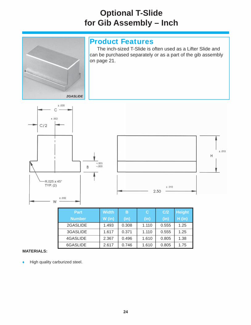
Optional T-Slide for Gib Assembly – Inch
MATERIALS:
High quality carburized steel.
Part Width B C C/2 Height Number W (in) (in) (in) (in) H (in) 2GASLIDE 1.493 0.308 1.110 0.555 1.25 3GASLIDE 1.617 0.371 1.110 0.555 1.25 4GASLIDE 2.367 0.496 1.610 0.805 1.38 6GASLIDE 2.617 0.746 1.610 0.805 1.75
2GASLIDE
The inch-sized T-Slide is often used as a Lifter Slide and can be purchased separately or as a part of the gib assembly on page 21.
Product Features

25
www.danly.com
Part L W T Mounting Hole Pattern & Location G Number (in) (in) (in) A (in) B (in) C (in) D (in) E (in) F (in) M (in) (in) 6SG32G 4.00 1.00 0.75 1.00 2.00 3.00 – – – 0.625 3/8 6SG40G 5.00 2.50 4.00 – – – – 6SG48G 6.00 3.00 5.00 – – – 6SG64G 8.00 3.00 5.00 7.00 – – 6SG80G 10.00 3.00 5.00 7.00 9.00 – 6SG96G 12.00 3.00 5.00 7.00 9.00 11.00 6SG96NG 12.00 – – – – – – – – 8SG32G 4.00 1.25 1.00 1.00 2.00 3.00 – – – 0.875 8SG40G 5.00 2.50 4.00 – – – 8SG48G 6.00 3.00 5.00 – – – 8SG64G 8.00 3.00 5.00 7.00 – – 8SG80G 10.00 3.00 5.00 7.00 9.00 – 8SG96G 12.00 3.00 5.00 7.00 9.00 11.00 8SG96NG 12.00 – – – – – – – – 12SG64G 8.00 2.00 1.50 1.50 4.00 6.50 – – – 1.250 12SG80G 10.00 1.25 3.75 6.25 8.75 – – 12SG96G 12.00 1.50 4.50 7.50 10.50 – – 12SG96NG 12.00 – – – – – – – –
0.875 0.62
FOR MOUNTING SCREWS
Self-LubricatingSquare Gibs – Inch
MATERIALS:
Aluminum bronze material with oil-impregnated graphite plugs. The plugs cover 25-30% of the wear surface.
TOLERANCES:
Unless otherwise noted ± 0.010 in.
MOUNTING SCREWS: 3/8" S.H.C.S recommended
Part numbers 6SG96NG, 8SG96NG and 12SG96NG do not include mounting holes.
1.00 0.75
1.25 1.00
2.00 1.50
1.00
1.00
0.625 0.39
0.625 0.86
These self-lubricating square gibs are manufactured in inch sizes from 1" to 2" wide and in lengths up to 12". They come standard with mounting holes for ease of assembly. The 12" lengths are available with or without mounting holes.
Product Features
8SG32G

26
www.danly.com
Self-LubricatingL-Gibs – Inch
Part # with Part # W/O Length Width Height Mounting Hole Pattern & Location Mounting Mounting L W H A B C D E F G J K M N Holes Holes (in) (in) (in) (in) (in) (in) (in) (in) (in) (in) (in) (in) # holes size (in) 2LG42G 2LG42NG 5.25 0.75 0.75 0.312 0.18 0.56 0.28 0.88 – 2.62 – 4.38 3 1/4“O .25
2LG56G 2LG56NG 7.00 0.88 2.62 – 4.38 6.12 4
2LG70G 2LG70NG 8.75 0.88 2.62 4.38 6.12 7.88 5
3LG48G 3LG48NG 6.00 1.00 0.75 0.375 0.25 0.75 0.38 1.00 – 3.00 – 5.00 3 5/16“ .31
3LG64G 3LG64NG 8.00 1.00 3.00 – 5.00 7.00 4
3LG80G 3LG80NG 10.00 1.00 3.00 5.00 7.00 9.00 5
4LG48G 4LG48NG 6.00 1.25 0.88 0.500 0.38 0.88 0.44 1.00 – 3.00 – 5.00 3 3/8“O 0.50
4LG60G 4LG60NG 7.50 1.25 – 3.75 – 6.25 3
4LG80G 4LG80NG 10.00 1.25 3.75 – 6.25 8.75 4
4LG100G 4LG100NG 12.50 1.25 3.75 6.25 8.75 11.25 5
6LG48G 6LG48NG 6.00 1.50 1.25 0.750 0.50 1.00 0.50 1.00 – 3.00 – 5.00 3 3/8“O .75
6LG72G 6LG72NG 9.00 1.50 – 4.50 – 7.50 3
6LG96G 6LG96NG 12.00 1.50 4.50 – 7.50 10.50 4
6LG120G 6LG120NG 15.00 1.50 4.50 7.50 10.50 13.50 5
7LG64G 7LG64NG 8.00 2.00 1.50 0.875 0.62 1.37 0.68 1.00 3.00 – 5.00 7.00 4 1/2“O .75
7LG96G 7LG96NG 12.00 1.50 4.50 – 7.50 10.50 4
7LG128G 7LG128NG 16.00 2.00 6.00 – 10.00 14.00 4
10LG96G 10LG96NG 12.00 2.50 2.00 1.250 0.75 1.75 0.88 1.50 4.50 – 7.50 10.50 4 5/8“O 1.25
10LG144G 10LG144NG 18.00 2.25 6.75 – 11.25 15.75 4
10LG192G 10LG192NG 24.00 3.00 9.00 – 15.00 21.00 4
12LG96G 12LG96NG 12.00 3.00 2.50 1.500 1.00 2.00 1.00 1.50 4.50 – 7.50 10.50 4 5/8“O 1.75
12LG144G 12LG144NG 18.00 2.25 6.75 – 11.25 15.75 4
12LG192G 12LG192NG 24.00 3.00 9.00 – 15.00 21.00 4
MATERIALS:
Aluminum bronze material with oil-impregnated graphite plugs. The plugs cover 25-30% of the wear surface.
TOLERANCES:
Mounting hole locations ± 0.010 in. Unless otherwise noted ± 0.010 in.
1.00 0.75 0.375 0.25 0.75 0.38
0.75 0.75 0.312 0.18 0.56 0.28
1.25 0.88 0.500 0.38 0.88 0.44
1.50 1.25 0.750 0.50 1.00 0.50
2.00 1.50 0.875 0.62 1.37 0.68
3.00 2.50 1.500 1.00 2.00 1.00
1/4 or .25 M6
5/16 or .31 M8
3/8 or .50 M10
3/8 or .75 M10
1/2 or .75M12
5/8 or 1.75M16
These self-lubricating L-Gibs are manufactured in inch sizes from 3/4" to 3" wide and in lengths up to 24". They are available with or without mounting holes.
Product Features
3LG48G
5/8 or 1.25 M16
2.50 2.00 1.250 0.75 1.75 0.88

27
www.danly.com
MATERIALS:
Aluminum bronze material with oil-impregnated graphite plugs. The plugs cover 25-30% of the wear surface.
TOLERANCES:
Unless otherwise noted ± 0.25 in.
MOUNTING SCREWS:
M10 S.H.C.S. recommended. 11mm through hole, 18mm Counterbore.
MOUNTING HOLES
Self-Lubricating L-Gibs – Metric
Part FIAT Length Width Mounting Hole Location Hole Number Code # L W A B C D E F G H J K Qty. (mm) (mm) (mm) (mm) (mm) (mm) (mm) (mm) (mm) (mm) (mm) (mm)
15LG100G BR-15 100 32 20 – – – 80 10 11 22 15 30 2 15LG150G BR-16 150 – 75 – 130 3 15LG200G – 200 75 – 125 180 4 15LG250G – 250 90 – 160 230 4 25LG200G BR-17 200 50 20 75 – 125 180 22 14 28 25 45 – 25LG250G BR-18 250 90 – 160 230 – 25LG300G – 300 85 150 215 280 – 25LG350G – 350 100 175 250 330 –
50 20
32 20 10 11 22 15 30
22 14 28 25 45
15LG100G
These self-lubricating L-Gibs are manufactured in metric sizes in 32 and 50mm widths and in lengths up to 350mm.They come standard with mounting holes to accommodatean M10 S.H.C.S.
Product Features

28
www.danly.com
Self-Lubricating 10mm LIP Cam Slide Gibs
MATERIALS:
Manufactured from high quality carburized steel precision ground and hardened to Rc56-62 with oil-impregnated graphite plugs covering 20-30% of the wear surface.
TOLERANCES:
Mounting hole locations ± 0.25mm
Dowel hole locations ± 0.10mm
Unless otherwise noted: ± 0.25mm
Break edges 0.4 x 45°
MOUNTING SCREWS:
M16 S.H.C.S. recommended for mounting
M16 dowel holes optional
Part NAAMS Length Hole Mounting Hole Location
Number Code L (mm) Quantity A B C D E Q75KF160GL R127516 160 3 – 80 – 140 144 Q75KF200GL R127520 200 3 – 100 – 180 184 Q75KF250GL R127525 250 4 90 – 160 230 234 Q75KF315GL R127531 315 5 89 157 225 295 299
Q75KF160GL
These Gibs fully conform to the NAAMS standard. They are manufactured from hardened steel with graphite plugs for self- lubricating operation. They are available with dowel holes for location. For ease of identifi cation, all plates are marked with the part number and NAAMS code.
Product Features
NOTE: Remove "Q" prefi x for unfi nished dowel holes.

29
www.danly.com
Self-Lubricating 13mm LIP Cam Slide Gibs
MATERIALS:
Manufactured from high quality carburized steel precision ground and hardened to Rc56-62 with oil-impregnated graphite plugs covering 20-30% of the wear surface.
TOLERANCES:
Mounting hole locations ± 0.25mm
Dowel hole locations ± 0.10mm
Unless otherwise noted: ± 0.25mm
Break edges 0.4 x 45°
MOUNTING SCREWS:
M12 S.H.C.S. recommended for mounting
M12 dowel holes optional
Part NAAMS Length Hole Mounting Hole Location
Number Code L (mm) Quantity A B C D E F G Q40KF160GL R114016 160 3 12 25 80 – – 135 148 Q40KF200GL R114020 200 3 12 25 100 – – 175 188 Q40KF250GL R114025 250 4 12 25 90 – 160 225 238 Q40KF315GL R114031 315 5 12 25 90 157.5 225 290 303
Q40KF160GL
These Gibs fully conform to the NAAMS standard. They are manufactured from hardened steel with graphite plugs for self- lubricating operation. They are available with dowel holes for location. For ease of identifi cation, all plates are marked with the part number and NAAMS code.
Product Features
NOTE: Remove "Q" prefi x for unfi nished dowel holes.

30
www.danly.com
Self-LubricatingU & V Blocks – Inch
U Block V Block Length Mounting Mounting Hole Locations Part Number Part Number L (in) Hole Qty. A (in) B (in) C (in) D (in) E (in) Q23UY48G Q23VS48 6.00 2 0.75 1.75 – 4.25 5.25 Q23UY64G Q23VS64 8.00 2 1.00 2.00 – 6.00 7.00 Q23UY80G Q23VS80 10.00 3 1.00 2.00 5.00 8.00 9.00
FIGURE AAluminum BronzeU-Block
FIGURE BSteelV-Block
FIGURE CAssembly
MATERIALS:
V Blocks are manufactured from high quality carburized steel. They are precision ground and hardened to Rc56-62.
U Blocks are manufactured from aluminum bronze material with oil-impregnated graphite plugs.
TOLERANCES:
Unless otherwise noted ± 0.010 in.
MOUNTING SCREWS:
1/2" S.H.C.S. recommended for mounting. Plate has 17/32" drill through 25/32" counterbore.
Q23UY48G & Q23VS48
These U and V Blocks are manufactured to inch dimensions. The V Block is manufactured from hardened steel and the U block is self-lubricating aluminum bronze with oil-impregnated graphite plugs. The blocks are provided with 1/2" dowel holes and are drilled and counterbored to accommodate 1/2" S.H.C.S. for mounting.
Product Features

31
www.danly.com
Self-LubricatingU & V Blocks – Inch
U Block V Block Length Mounting Mounting Hole Locations Part Number Part Number L (in) Hole Qty. A (in) B (in) C (in) D (in) E (in) Q39UY48G Q39VS48 6.00 2 0.75 1.75 – 4.25 5.25 Q39UY64G Q39VS64 8.00 2 1.00 2.00 – 6.00 7.00 Q39UY80G Q39VS80 10.00 3 1.00 2.00 5.00 8.00 9.00
FIGURE AAluminum BronzeU-Block
FIGURE BSteelV-Block
FIGURE CAssembly
MATERIALS:
V Blocks are manufactured from high quality carburized steel. They are precision ground and hardened to Rc56-62.
U Blocks are manufactured from aluminum bronze material with oil-impregnated graphite plugs.
TOLERANCES:
Unless otherwise noted ± 0.010 in.
MOUNTING SCREWS:
5/8" S.H.C.S. recommended for mounting. Plate has 21/32" drill through 1"counterbore.
Q39UY48G & Q39VS48
These U and V Blocks are manufactured to inch dimensions. The V Block is manufactured from hardened steel and the U block is self-lubricating aluminum bronze with oil-impregnated graphite plugs. The blocks are provided with 5/8" dowel holes and are drilled and counterbored to accommodate 5/8" S.H.C.S. for mounting.
Product Features

32
www.danly.com
NAAMSU & V Blocks – Metric
Q75US150 & Q75VS150G
These 65, 75, 125 and 175mm U and V Blocks are manufactured to metric dimensions and fully meet the NAAMS standard. The U Block is manufactured from hardened steel. The V block is self-lubricating in design and is available in either aluminum bronze with oil-impregnated graphite plugs or steel with oil-impregnated graphite plugs.
Product Features
FIGURE A - Steel U Block
FIGURE C - Assembly
FIGURE B - Self-lubricating V Block
MATERIALS:
U Blocks are manufactured from high quality carburized steel. They are precision ground and hardened to Rc56-62.
V Blocks are manufactured from aluminum bronze material with oil-impregnated graphite plugs or steel with oil-impregnated graphite plugs.
TOLERANCES:
Between screw holes: ± 0.12mm Between dowel holes: ± 0.10mm Unless otherwise noted: ± 0.25mm
RECOMMENDED MOUNTING SCREWS & DOWELS:
65mm blocks: M12 S.H.C.S./M12 DOWELS 75mm blocks: M12 S.H.C.S. /M12 DOWELS 125mm blocks: M16 S.H.C.S. M16 DOWELS 175mm blocks: M16 S.H.C.S. M16 DOWELS

33
www.danly.com
NAAMS U & V Blocks – Metric
U Block Steel V Block Bronze V Block Width Length Part NAAMS Part NAAMS Part NAAMS W L Hole A B C H1 H2 H3 Number Code Number Code Number Code (mm) (mm) Qty. (mm) (mm) (mm) (mm) (mm) (mm) Q65US150 G157515 Q65VS150G G167515 Q65VY150G G177515 65 150 2 – 100 125 65 39 40 Q65US200 G157520 Q65VS200G G167520 Q65VY200G G177520 65 200 2 – 150 175 65 39 40 Q65US250 G157525 Q65VS250G G167525 Q65VY250G G177525 65 250 3 125 200 225 65 39 40 Q65US300 G157530 Q65VS300G G167530 Q65VY300G G177530 65 300 3 150 250 275 65 39 40 Q75US150 G217515 Q75VS150G G227515 Q75VY150G G237515 75 150 2 – 100 125 65 39 40 Q75US200 G217520 Q75VS200G G227520 Q75VY200G G237520 75 200 2 – 150 175 65 39 40 Q75US250 G217525 Q75VS250G G227525 Q75VY250G G237525 75 250 3 125 200 225 65 39 40 Q75US300 G217530 Q75VS300G G227530 Q75VY300G G237530 75 300 3 150 250 275 65 39 40 Q125US150 G311215 Q125VS150G G321215 Q125VY150G G331215 125 150 2 – 100 125 85 52 60 Q125US200 G311220 Q125VS200G G321220 Q125VY200G G331220 125 200 2 – 150 175 85 52 60 Q125US250 G311225 Q125VS250G G321225 Q125VY250G G331225 125 250 3 125 200 225 85 52 60 Q125US300 G311230 Q125VS300G G321230 Q125VY300G G331230 125 300 3 150 250 275 85 52 60 Q175US150 G341715 Q175VS150G G351715 Q175VY150G G361715 175 150 2 – 100 125 110 67 80 Q175US200 G341720 Q175VS200G G351720 Q175VY200G G361720 175 200 2 – 150 175 110 67 80

34
www.danly.com
Self-Lubricating 45mm Guide Blocks – Metric
MATERIALS:
High quality carburized steel with oil-impregnated graphite plugs. They are precision ground and hardened to Rc56-62.
TOLERANCES:
Mounting hole locations ± 0.25mm
Dowel holes ± 0.10mm
MOUNTING SCREWS:
M12 S.H.C.S. recommended for mounting.
Q40G75G
These guide blocks fully meet the NAAMS standard. The oil-impregnated graphite plugs cover 20-30% of the wear surface, ensuring self-lubrication. They are available with or without dowel holes. For ease of identifi cation, all parts are marked with the part number and NAAMS code.
Product Features

35
www.danly.com
Self-Lubricating 45mm Guide Blocks – Metric
Length Hole Mounting Hole Location Part NAAMS L Qty. A B C D E F Number Code (mm) (mm) (mm) (mm) (mm) (mm) (mm) Q40G75G G 014007 75 2 – – 50 63 40 25 Q40G100G G 014010 100 2 – – 75 88 Q40G125G G 014012 125 3 – 62.5 100 113 Q40G150G G 014015 150 3 – 75.0 125 138 Q40G175G G 014017 175 3 – 87.5 150 163 Q40G200G G 014020 200 4 75 125.0 175 188 Q40G225G G 014022 225 4 85 140.0 200 213 Q40G250G G 014025 250 4 95 165.0 225 238 Q45G75G G 014507 75 2 – – 50 63 45 20 Q45G100G G 014510 100 2 – – 75 88 Q45G125G G 014512 125 3 – 62.5 100 113 Q45G150G G 014515 150 3 – 75.0 125 138 Q45G175G G 014517 175 3 – 87.5 150 163 Q45G200G G 014520 200 4 75 125.0 175 188 Q45G225G G 014522 225 4 85 140.0 200 213 Q45G250G G 014525 250 4 95 165.0 225 238 Q50G75G G 015007 75 2 – – 50 63 50 20 Q50G100G G 015010 100 2 – – 75 88 Q50G125G G 015012 125 3 – 62.5 100 113 Q50G150G G 015015 150 3 – 75.0 125 138 Q50G175G G 015017 175 3 – 87.5 150 163 Q50G200G G 015020 200 4 75 125.0 175 188 Q50G225G G 015022 225 4 85 140.0 200 213 Q50G250G G 015025 250 4 95 165.0 225 238 Q60G75G G 016007 75 2 – – 50 63 60 30 Q60G100G G 016010 100 2 – – 75 88 Q60G125G G 016012 125 3 – 62.5 100 113 Q60G150G G 016015 150 3 – 75.0 125 138 Q60G175G G 016017 175 3 – 87.5 150 163 Q60G200G G 016020 200 4 75 125.0 175 188 Q60G225G G 016022 225 4 85 140.0 200 213 Q60G250G G 016025 250 4 95 165.0 225 238 Q75G75G G 017507 75 2 – – 50 63 75 45 Q75G100G G 017510 100 2 – – 75 88 Q75G125G G 017512 125 3 – 62.5 100 113
40 25
50 20
75 45
60 30
45 20
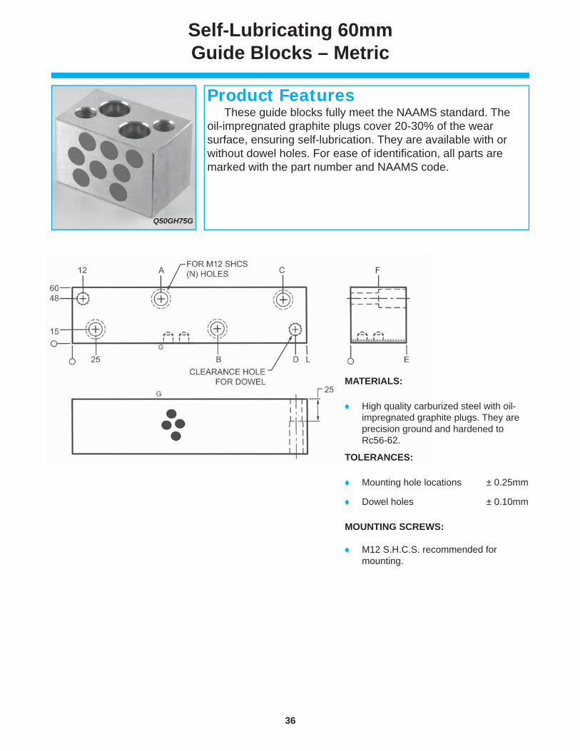
36
www.danly.com
Q50GH75G
Self-Lubricating 60mm Guide Blocks – Metric
MATERIALS:
High quality carburized steel with oil-impregnated graphite plugs. They are precision ground and hardened to Rc56-62.
TOLERANCES:
Mounting hole locations ± 0.25mm
Dowel holes ± 0.10mm
MOUNTING SCREWS:
M12 S.H.C.S. recommended for mounting.
These guide blocks fully meet the NAAMS standard. The oil-impregnated graphite plugs cover 20-30% of the wear surface, ensuring self-lubrication. They are available with or without dowel holes. For ease of identifi cation, all parts are marked with the part number and NAAMS code.
Product Features

37
www.danly.com
Self-Lubricating 60mm Guide Blocks – Metric
Length Hole Mounting Hole Location Part NAAMS L Qty. A B C D E F Number Code (mm) (mm) (mm) (mm) (mm) (mm) (mm) Q50GH75G G 025007 75 2 – – 50 63 50 20 Q50GH100G G 025010 100 2 – – 75 88 Q50GH125G G 025012 125 3 – 62.5 100 113 Q50GH150G G 025015 150 3 – 75.0 125 138 Q50GH175G G 025017 175 3 – 87.5 150 163 Q50GH200G G 025020 200 4 75 125.0 175 188 Q50GH225G G 025022 225 4 85 140.0 200 213 Q50GH250G G 025025 250 4 95 165.0 225 238 Q60GH75G G 026007 75 2 – – 50 63 60 30 Q60GH100G G 026010 100 2 – – 75 88 Q60GH125G G 026012 125 3 – 62.5 100 113 Q60GH150G G 026015 150 3 – 75.0 125 138 Q60GH175G G 026017 175 3 – 87.5 150 163 Q60GH200G G 026020 200 4 75 125.0 175 188 Q60GH225G G 026022 225 4 85 140.0 200 213 Q60GH250G G 026025 250 4 95 165.0 225 238 Q80GH75G G 028007 75 2 – – 50 63 80 50 Q80GH100G G 028010 100 2 – – 75 88 Q80GH125G G 028012 125 3 – 62.5 100 113 Q80GH150G G 028015 150 3 – 75.0 125 138 Q80GH175G G 028017 175 3 – 87.5 150 163 Q80GH200G G 028020 200 4 75 125.0 175 188 Q80GH225G G 028022 225 4 85 140.0 200 213 Q80GH250G G 028025 250 4 95 165.0 225 238 Q100GH75G G 020007 75 2 – – 50 63 100 70 Q100GH100G G 020010 100 2 – – 75 88 Q100GH125G G 020012 125 3 – 62.5 100 113 Q100GH150G G 020015 150 3 – 75.0 125 138 Q100GH175G G 020017 175 3 – 87.5 150 163 Q100GH200G G 020020 200 4 75 125.0 175 188 Q100GH225G G 020022 225 4 85 140.0 200 213 Q100GH250G G 020025 250 4 95 165.0 225 238
50 20
80 50
100 70
60 30

38
www.danly.com
MATERIALS:
High quality carburized steel with oil-impregnated graphite plugs. They are precision ground and hardened to Rc56-62.
MOUNTING SCREWS:
1/2" S.H.C.S. recommended for mounting
Medium Duty Self-Lubricating Guide Blocks – Inch
FOR 3.0" & 4.0" LENGTHS
FOR 8.0" TO 10.0" LENGTHS
FOR 5.0" & 6.0" LENGTHS
16G24G
These medium duty guide blocks are manufactured from hardened steel with oil-impregnated graphite plugs covering 20-30% of the wear surface. The blocks are supplied with mounting holes for 1/2" S.H.C.S. All blocks are marked with the part number for ease of identifi cation.
Product Features

39
www.danly.com
Medium Duty Self-Lubricating Guide Blocks – Inch
Length Mounting Mounting Hole Location L Hole A B C D E F (in) Quantity (in) (in) (in) (in) (in) (in) 3.00 2 0.50 1.00 2.00 2.50 – – 4.00 3 3.00 3.50 – – 5.00 3 2.50 4.00 4.50 – 6.00 3 3.00 5.00 5.50 – 8.00 4 2.38 5.62 7.00 7.50 10.00 4 3.50 6.50 9.00 9.50
GEN
ERA
L D
IMEN
SIO
NS
.50 1.00
Part Length G H Number L (in) (in) (in) 14G24G 3 1.00 1.69 14G32G 4 14G40G 5 14G48G 6 14G64G 8 14G80G 10 16G24G 3 1.25 1.94 16G32G 4 16G40G 5 16G48G 6 16G64G 8 16G80G 10 20G24G 3 1.25 2.44 20G32G 4 20G40G 5 20G48G 6 20G64G 8 20G80G 10 24G24G 3 1.25 2.94 24G32G 4 24G40G 5 24G48G 6 24G64G 8 24G80G 10
1.00 1.69
1.25 2.44
1.25 1.94
1.25 2.94

40
www.danly.com
Self-LubricatingCorner Guide Blocks – Metric
MATERIALS:
High quality carburized steel with oil-impregnated graphite plugs. They are precision ground and hardened to Rc56-62.
TOLERANCES:
Mounting hole locations ± 0.25mm
Dowel holes ± 0.10mm
MOUNTING SCREWS:
M16 S.H.C.S. recommended for mounting
Thickness Length Part NAAMS T L A B Number Code (mm) (mm) (mm) (mm) Q80GD75G G118007 75 80 55 60 Q80GD100G G118010 100 Q80GD125G G118012 125 Q95GD75G G119507 75 95 70 75 Q95GD100G G119510 100 Q95GD125G G119512 125 Q120GD75G G111207 75 120 95 100 Q120GD100G G111210 100 Q120GD125G G111212 125
80 55 60
95 70 75
120 95 100
Q80GD100G
These metric corner guide blocks fully meet the NAAMS standard. The oil-impregnated graphite plugs cover 20-30% of the wear surface, ensuring self-lubrication. They are available with dowel holes.
Product Features

41
www.danly.com
Self-LubricatingCenter Key & Guide – Metric
MATERIALS:
Center Key Guide is manufactured from high quality carburized steel. The wear surfaces are precision ground and hardened to Rc56-62.
Center Key is manufactured from high quality carburized steel with oil-impregnated graphite plugs covering 20-30% of the wear surface. The wear surface is precision ground andhardened to Rc56-62. The product is also available as a special in aluminum bronze material.
TOLERANCES:
Mounting hole locations ± 0.25 mm
Dowel hole locations ± 0.10 mm
MOUNTING SCREWS:
M12 S.H.C.S. are recommended for mounting.
FIGURE A Center Key Guide
FIGURE B Center Key
Part Steel Bronze Length Mounting A B C Figure Number NAAMS Code NAAMS Code L (mm) Hole Qty. (mm) (mm) (mm) 4044GUIDE200 G419020 N/A 200 2 – 135 160 A 4044GUIDE300 G419030 N/A 300 3 150 235 260 A 4044KEY200G G424020 – 200 2 – 135 160 B 4044KEY300G G424030 – 300 3 150 235 260 B 4044KEY200GBRZ – G434020 200 2 – 135 160 B 4044KEY300GBRZ – G434030 300 3 150 235 260 B
4044GUIDE200 & 4044KEY200G
The Center Key and Center Key Guide are available in 200 and 300mm lengths and fully meet the NAAMS standard. They come standard with M12 dowel holes for location and are drilled to accommodate M12 S.H.C.S. for mounting.
Product Features
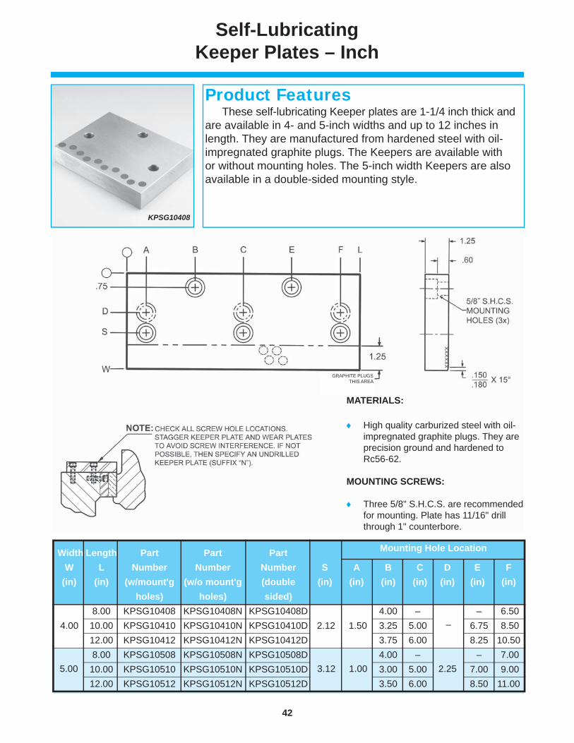
42
www.danly.com
Self-LubricatingKeeper Plates – Inch
MATERIALS:
High quality carburized steel with oil-impregnated graphite plugs. They are precision ground and hardened to Rc56-62.
MOUNTING SCREWS:
Three 5/8" S.H.C.S. are recommended for mounting. Plate has 11/16" drill through 1" counterbore.
GRAPHITE PLUGSTHIS AREA
KPSG10408
These self-lubricating Keeper plates are 1-1/4 inch thick and are available in 4- and 5-inch widths and up to 12 inches in length. They are manufactured from hardened steel with oil-impregnated graphite plugs. The Keepers are available with or without mounting holes. The 5-inch width Keepers are also available in a double-sided mounting style.
Product Features
Width Length Part Part Part W L Number Number Number S A B C D E F (in) (in) (w/mount'g (w/o mount'g (double (in) (in) (in) (in) (in) (in) (in) holes) holes) sided) 4.00 8.00 KPSG10408 KPSG10408N KPSG10408D 2.12 1.50 4.00 – – – 6.50 4.00 10.00 KPSG10410 KPSG10410N KPSG10410D 2.12 1.50 3.25 5.00 – 6.75 8.50 4.00 12.00 KPSG10412 KPSG10412N KPSG10412D 2.12 1.50 3.75 6.00 – 8.25 10.50 5.00 8.00 KPSG10508 KPSG10508N KPSG10508D 3.12 1.00 4.00 – 2.25 – 7.00 5.00 10.00 KPSG10510 KPSG10510N KPSG10510D 3.12 1.00 3.00 5.00 2.25 7.00 9.00 5.00 12.00 KPSG10512 KPSG10512N KPSG10512D 3.12 1.00 3.50 6.00 2.25 8.50 11.00
4.00
5.00
2.12
3.12
1.50
1.00
–
2.25
Mounting Hole Location
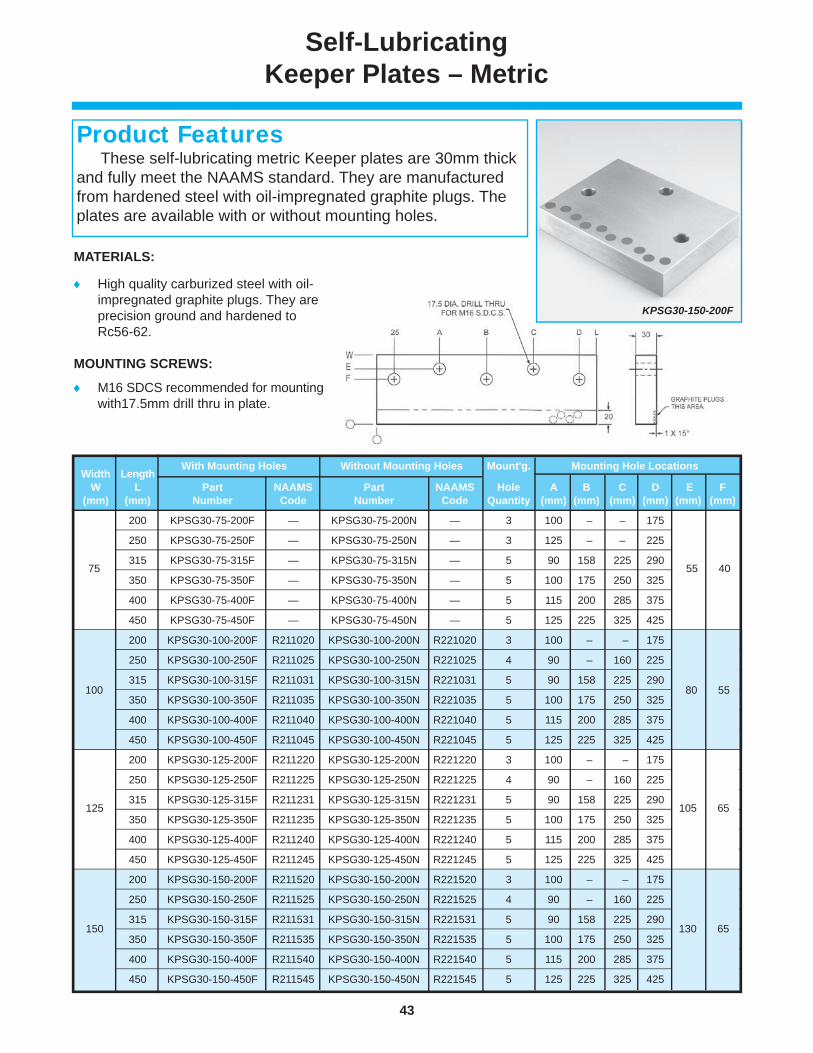
43
www.danly.com
Self-LubricatingKeeper Plates – Metric
MATERIALS:
High quality carburized steel with oil-impregnated graphite plugs. They are precision ground and hardened to Rc56-62.
MOUNTING SCREWS:
M16 SDCS recommended for mounting with17.5mm drill thru in plate.
KPSG30-150-200F
These self-lubricating metric Keeper plates are 30mm thick and fully meet the NAAMS standard. They are manufactured from hardened steel with oil-impregnated graphite plugs. The plates are available with or without mounting holes.
Product Features
Width Length With Mounting Holes Without Mounting Holes Mount'g. Mounting Hole Locations
W L Part NAAMS Part NAAMS Hole A B C D E F (mm) (mm) Number Code Number Code Quantity (mm) (mm) (mm) (mm) (mm) (mm)
100 200 KPSG30-75-200F — KPSG30-75-200N — 3 100 – – 175 80 55
100 250 KPSG30-75-250F — KPSG30-75-250N — 3 125 – – 225
100 315 KPSG30-75-315F — KPSG30-75-315N — 5 90 158 225 290
100 350 KPSG30-75-350F — KPSG30-75-350N — 5 100 175 250 325
100 400 KPSG30-75-400F — KPSG30-75-400N — 5 115 200 285 375
100 450 KPSG30-75-450F — KPSG30-75-450N — 5 125 225 325 425
200 KPSG30-100-200F R211020 KPSG30-100-200N R221020 3 100 – – 175 80 55
100 250 KPSG30-100-250F R211025 KPSG30-100-250N R221025 4 90 – 160 225
100 315 KPSG30-100-315F R211031 KPSG30-100-315N R221031 5 90 158 225 290
100 350 KPSG30-100-350F R211035 KPSG30-100-350N R221035 5 100 175 250 325
100 400 KPSG30-100-400F R211040 KPSG30-100-400N R221040 5 115 200 285 375
100 450 KPSG30-100-450F R211045 KPSG30-100-450N R221045 5 125 225 325 425
125 200 KPSG30-125-200F R211220 KPSG30-125-200N R221220 3 100 – – 175 105 65
125 250 KPSG30-125-250F R211225 KPSG30-125-250N R221225 4 90 – 160 225
125 315 KPSG30-125-315F R211231 KPSG30-125-315N R221231 5 90 158 225 290
125 350 KPSG30-125-350F R211235 KPSG30-125-350N R221235 5 100 175 250 325
125 400 KPSG30-125-400F R211240 KPSG30-125-400N R221240 5 115 200 285 375
125 450 KPSG30-125-450F R211245 KPSG30-125-450N R221245 5 125 225 325 425
150 200 KPSG30-150-200F R211520 KPSG30-150-200N R221520 3 100 – – 175 130 65
150 250 KPSG30-150-250F R211525 KPSG30-150-250N R221525 4 90 – 160 225
150 315 KPSG30-150-315F R211531 KPSG30-150-315N R221531 5 90 158 225 290
150 350 KPSG30-150-350F R211535 KPSG30-150-350N R221535 5 100 175 250 325
150 400 KPSG30-150-400F R211540 KPSG30-150-400N R221540 5 115 200 285 375
150 450 KPSG30-150-450F R211545 KPSG30-150-450N R221545 5 125 225 325 425
80 55
130 65
105 65
100
150
125
75 55 40
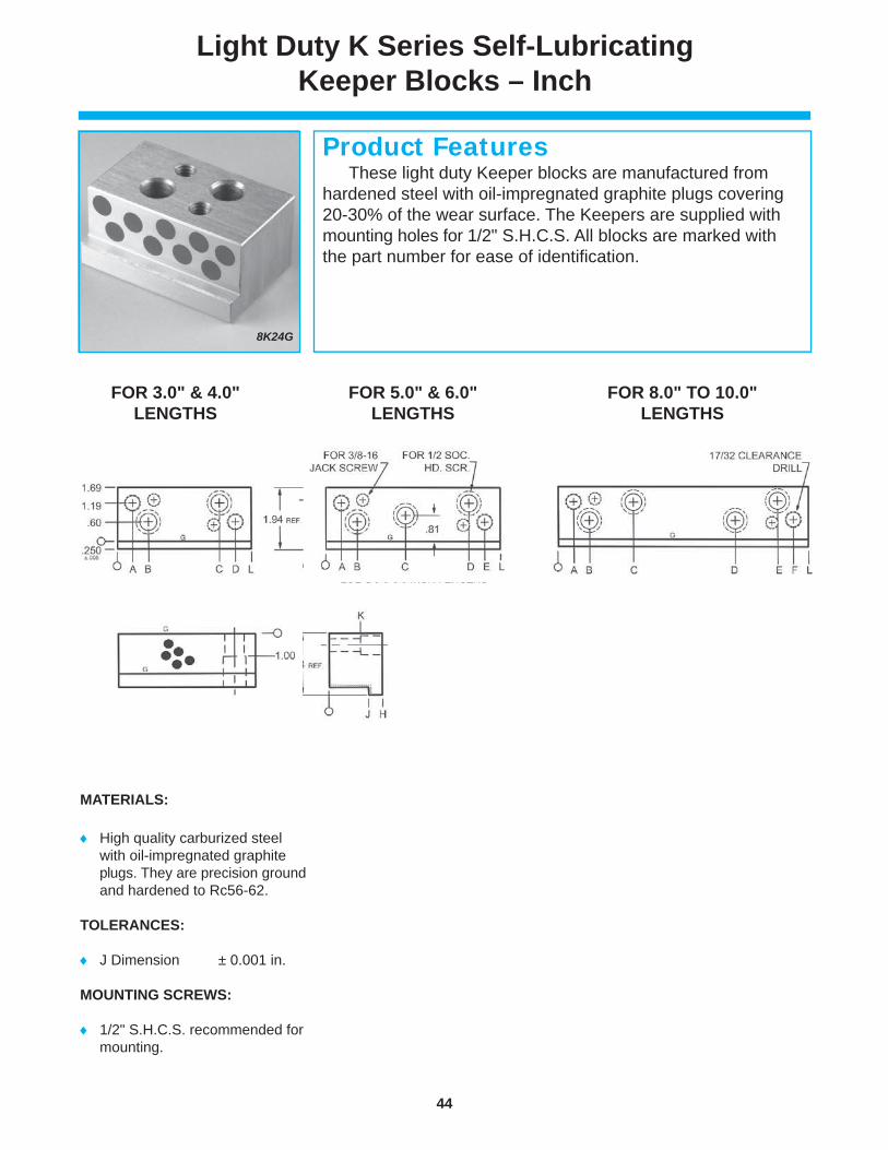
44
www.danly.com
Light Duty K Series Self-Lubricating Keeper Blocks – Inch
MATERIALS:
High quality carburized steel with oil-impregnated graphite plugs. They are precision ground and hardened to Rc56-62.
TOLERANCES:
J Dimension ± 0.001 in.
MOUNTING SCREWS:
1/2" S.H.C.S. recommended for mounting.
FOR 3.0" & 4.0" LENGTHS
FOR 8.0" TO 10.0" LENGTHS
FOR 5.0" & 6.0" LENGTHS
8K24G
These light duty Keeper blocks are manufactured from hardened steel with oil-impregnated graphite plugs covering 20-30% of the wear surface. The Keepers are supplied with mounting holes for 1/2" S.H.C.S. All blocks are marked with the part number for ease of identifi cation.
Product Features

45
www.danly.com
Light Duty K Series Self-Lubricating Keeper Blocks – Inch
Part Length H J K Number L (in) (in) (in) (in) 8K24G 3.00 1.44 1.000 0.94 8K32G 4.00 8K40G 5.00 8K48G 6.00 8K64G 8.00 8K80G 10.00 10K24G 3.00 1.69 1.250 1.00 10K32G 4.00 10K40G 5.00 10K48G 6.00 10K64G 8.00 10K80G 10.00 12K24G 3.00 1.94 1.500 1.25 12K32G 4.00 12K40G 5.00 12K48G 6.00 12K64G 8.00 12K80G 10.00 14K24G 3.00 21.44 1.750 1.25 14K32G 4.00 14K40G 5.00 14K48G 6.00 14K64G 8.00 14K80G 10.00
Length Mounting Mounting Hole Location L Hole A B C D E F (in) Quantity (in) (in) (in) (in) (in) (in) 3.00 2 0.50 1.00 2.00 2.50 – – 4.00 2 0.50 1.00 3.00 3.50 – – 5.00 3 0.50 1.00 2.50 4.00 4.50 – 6.00 3 0.50 1.00 3.00 5.00 5.50 – 8.00 4 0.50 1.00 2.38 5.62 7.00 7.50 10.00 4 0.50 1.00 3.50 6.50 9.00 9.50
GEN
ERA
L D
IMEN
SIO
NS
0.50 1.00
1.44 1.000 0.94
1.94 1.500 1.25
1.69 1.250 1.00
2.44 1.750 1.25

46
www.danly.com
Medium Duty KM Series Self-Lubricating Keeper Blocks – Inch
FOR 3.0" LENGTHS
FOR 10.0" LENGTHS
FOR 8.0" LENGTHS
FOR 4.0" TO 6.0" LENGTHS
Part Length H J K Number L (in) (in) (in) (in) 8KM24G 3.00 1.62 1.000 1.00 8KM32G 4.00 8KM40G 5.00 8KM48G 6.00 8KM64G 8.00 8KM80G 10.00 10KM24G 3.00 1.88 1.250 1.25 10KM32G 4.00 10KM40G 5.00 10KM48G 6.00 10KM64G 8.00 10KM80G 10.00 12KM24G 3.00 2.12 1.500 1.50 12KM32G 4.00 12KM40G 5.00 12KM48G 6.00 12KM64G 8.00 12KM80G 10.00 14KM24G 3.00 2.44 1.750 1.25 14KM32G 4.00 14KM40G 5.00 14KM48G 6.00 14KM64G 8.00 14KM80G 10.00
1.62 1.000 1.00
2.12 1.500 1.50
1.69 1.250 1.00 1.88 1.250 1.25
2.44 1.750 1.25
8KM24G
These medium duty Keeper blocks are manufactured from hardened steel with oil-impregnated graphite plugs covering 20-30% of the wear surface. The Keepers are supplied with mounting holes for 1/2" S.H.C.S. All blocks are marked with the part number for ease of identifi cation.
Product Features
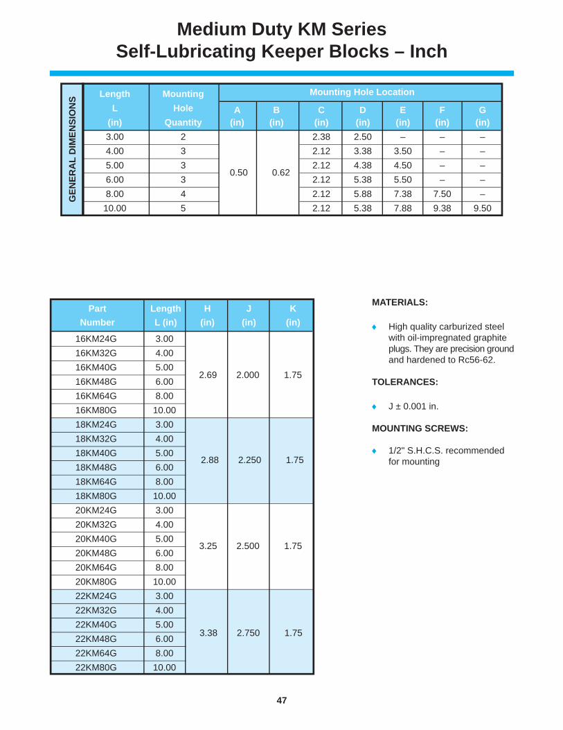
47
www.danly.com
Medium Duty KM Series Self-Lubricating Keeper Blocks – Inch
MATERIALS:
High quality carburized steel with oil-impregnated graphite plugs. They are precision ground and hardened to Rc56-62.
TOLERANCES:
J ± 0.001 in.
MOUNTING SCREWS:
1/2" S.H.C.S. recommended for mounting
Length Mounting Mounting Hole Location
L Hole A B C D E F G (in) Quantity (in) (in) (in) (in) (in) (in) (in) 3.00 2 0.50 0.62 2.38 2.50 – – – 4.00 3 2.12 3.38 3.50 – – 5.00 3 2.12 4.38 4.50 – – 6.00 3 2.12 5.38 5.50 – – 8.00 4 2.12 5.88 7.38 7.50 – 10.00 5 2.12 5.38 7.88 9.38 9.50
GEN
ERA
L D
IMEN
SIO
NS
0.50 0.62
16KM24G 3.00 2.69 2.000 1.75 16KM32G 4.00 16KM40G 5.00 16KM48G 6.00 16KM64G 8.00 16KM80G 10.00 18KM24G 3.00 2.88 2.250 1.75 18KM32G 4.00 18KM40G 5.00 18KM48G 6.00 18KM64G 8.00 18KM80G 10.00 20KM24G 3.00 3.25 2.500 1.75 20KM32G 4.00 20KM40G 5.00 20KM48G 6.00 20KM64G 8.00 20KM80G 10.00 22KM24G 3.00 3.38 2.750 1.75 22KM32G 4.00 22KM40G 5.00 22KM48G 6.00 22KM64G 8.00 22KM80G 10.00
Part Length H J K Number L (in) (in) (in) (in)
2.69 2.000 1.75
3.25 2.500 1.75
1.69 1.250 1.00 2.88 2.250 1.75
3.38 2.750 1.75

48
www.danly.com
Heavy Duty KH SeriesSelf-Lubricating Keeper Blocks
FOR 8.0" LENGTHS
FOR 4.0" TO 6.0" LENGTHS
FOR 10.0" LENGTHS
Part Length H J K Number L (in) (in) (in) (in) 14KH32G 4.00 2.62 1.750 1.50 14KH40G 5.00 14KH48G 6.00 14KH64G 8.00 14KH80G 10.00 14KH96G 12.00 16KH32G 4.00 2.88 2.000 1.50 16KH40G 5.00 16KH48G 6.00 16KH64G 8.00 16KH80G 10.00 16KH96G 12.00 18KH32G 4.00 3.12 2.250 1.50 18KH40G 5.00 18KH48G 6.00 18KH64G 8.00 18KH80G 10.00 18KH96G 12.00
2.62 1.750 1.50
3.12 2.250 1.50
2.88 2.000 1.50
14KH32G
These heavy duty Keeper blocks are manufactured from hardened steel with oil-impregnated graphite plugs covering 25% of the wear surface. The Keepers are supplied with mountingholes for 5/8" S.H.C.S. All blocks are marked with the part number for ease of identifi cation.
Product Features

49
www.danly.com
Heavy Duty KH SeriesSelf-Lubricating Keeper Blocks
MATERIALS:
High quality carburized steel with oil-impregnated graphite plugs. They are precision ground and hardened to Rc56-62.
TOLERANCES:
J Dimension ± 0.001 in.
MOUNTING SCREWS:
5/8" S.H.C.S. recommended for mounting
Length Mounting Mounting Hole Location L (in) Hole Qty. A (in) B (in) C (in) D (in) E (in) F (in) G (in) 4.00 3 0.62 0.75 2.25 3.25 3.38 – – 5.00 3 4.25 4.38 – – 6.00 3 5.25 5.38 – – 8.00 4 5.75 7.25 7.38 – 10.00 5 5.25 7.75 9.25 9.38 12.00 5 5.75 9.75 11.25 11.38G
ENER
AL
DIM
ENSI
ON
S
0.62 0.75 2.25
20KH32G 4.00 3.38 2.500 2.25 20KH40G 5.00 20KH48G 6.00 20KH64G 8.00 20KH80G 10.00 20KH96G 12.00 22KH32G 4.00 3.62 2.750 2.25 22KH40G 5.00 22KH48G 6.00 22KH64G 8.00 22KH80G 10.00 22KH96G 12.00 24KH32G 4.00 3.88 3.000 2.25 24KH40G 5.00 24KH48G 6.00 24KH64G 8.00 24KH80G 10.00 24KH96G 12.00
Part Length H J K Number L (in) (in) (in) (in)
3.38 2.500 2.25
3.88 3.000 2.25
3.62 2.750 2.25

50
www.danly.com
Self-Lubricating 6mm LIP Keeper Blocks – Metric
MATERIALS:
High quality carburized steel with oil-impregnated graphite plugs. They are precision ground and hardened to Rc56-62.
TOLERANCES:
Mounting hole locations ± 0.25mm
Dowel holes ± 0.10mm
MOUNTING SCREWS:
M12 S.H.C.S. recommended for mounting
Q25K75G
These metric Keeper blocks fully meet the NAAMS standard. The oil-impregnated graphite plugs cover 20-30% of the wear surface, ensuring self-lubrication. They are available with dowel holes. For ease of identifi cation, all parts are marked with the part number and NAAMS code.
Product Features

51
www.danly.com
Self-Lubricating 6mm LIP Keeper Blocks – Metric
Length Hole Mounting Hole Location Part NAAMS L Qty. A B C D E F H Number Code (mm) (mm) (mm) (mm) (mm) (mm) (mm) (mm) Q25K75G R 012507 75 2 – – 50 63 Q25K100G R 012510 100 2 – – 75 88 Q25K125G R 012512 125 3 – 62.5 100 113 Q25K150G R 012515 150 3 – 75.0 125 138 Q25K175G R 012517 175 3 – 87.5 150 163 Q25K200G R 012520 200 4 75 125.0 175 188 Q32K75G R 013207 75 2 – – 50 63 Q32K100G R 013210 100 2 – – 75 88 Q32K125G R 013212 125 3 – 62.5 100 113 Q32K150G R 013215 150 3 – 75.0 125 138 Q32K175G R 013217 175 3 – 87.5 150 163 Q32K200G R 013220 200 4 75 125.0 175 188 Q37K75G R 013707 75 2 – – 50 63 Q37K100G R 013710 100 2 – – 75 88 Q37K125G R 013712 125 3 – 62.5 100 113 Q37K150G R 013715 150 3 – 75.0 125 138 Q37K175G R 013717 175 3 – 87.5 150 163 Q37K200G R 013720 200 4 75 125.0 175 188 Q48K75G R 014807 75 2 – – 50 63 Q48K100G R 014810 100 2 – – 75 88 Q48K125G R 014812 125 3 – 62.5 100 113 Q48K150G R 014815 150 3 – 75.0 125 138 Q48K175G R 014817 175 3 – 87.5 150 163 Q48K200G R 014820 200 4 75 125.0 175 188 Q48K250G R 014825 250 4 95 165.0 225 238 Q55K75G R 015507 75 2 – – 50 63 Q55K100G R 015510 100 2 – – 75 88 Q55K125G R 015512 125 3 – 62.5 100 113 Q55K150G R 015515 150 3 – 75.0 125 138 Q55K175G R 015517 175 3 – 87.5 150 163 Q55K200G R 015520 200 4 75 125.0 175 188 Q55K250G R 015525 250 4 95 165.0 225 238
25.00 15 37
32.00 15 45
37.00 30 50
55.00 30 75
48.00 30 60
NOTE: Remove "Q" prefi x for unfi nished dowel holes.

52
www.danly.com
Self-Lubricating 13mm LIP Keeper Blocks – Metric
MATERIALS:
High quality carburized steel with oil-impregnated graphite plugs. They are precision ground and hardened to Rc56-62.
TOLERANCES:
Mounting hole locations ± 0.25mm
Dowel holes ± 0.10mm
MOUNTING SCREWS:
M16 S.H.C.S. recommended for mounting.
Part NAAMS Length Hole Mounting Hole Location
Number Code L Qty. A B C D E F G H (mm) (mm) (mm) (mm) (mm) (mm) (mm) (mm) (mm) Q35KN100G R 023510 100 2 – – – 78 87 35 25 50 Q35KN125G R 023512 125 3 62.5 – – 103 112 Q35KN150G R 023515 150 3 75.0 – – 128 137 Q35KN200G R 023520 200 4 75.0 – 125 178 187 Q35KN225G R 023522 225 5 75.0 112.5 150 203 212 Q35KN250G R 023525 250 5 75.0 125.0 175 228 237 Q35KN300G R 023530 300 5 75.0 150.0 225 278 287 Q40KN100G R 024010 100 2 – – – 78 87 40 25 60 Q40KN125G R 024012 125 3 62.5 – – 103 112 Q40KN150G R 024015 150 3 75.0 – – 128 137 Q40KN200G R 024020 200 4 75.0 – 125 178 187 Q40KN225G R 024022 225 5 75.0 112.5 150 203 212 Q40KN250G R 024025 250 5 75.0 125.0 175 228 237 Q40KN300G R 024030 300 5 75.0 150.0 225 278 287
35.00 25 50
40.00 25 60
Q35KN100G
These metric Keeper blocks fully meet the NAAMS standard. The oil-impregnated graphite plugs cover 20-30% of the wear surface, ensuring self-lubrication. They are available with dowel holes. For ease of identifi cation, all parts are marked with the part number and NAAMS code.
Product Features
NOTE: Remove "Q" prefi x for unfi nished dowel holes.

53
www.danly.com
Self-Lubricating 13mm LIP Keeper Blocks – Metric
Length Hole Mounting Hole Location
Part NAAMS L Qty. A B C D E F G H Number Code (mm) (mm) (mm) (mm) (mm) (mm) (mm) (mm) (mm) Q50KN100G R 025010 100 2 – – – 78 87 50 30 70 Q50KN125G R 025012 125 3 62.5 – – 103 112 Q50KN150G R 025015 150 3 75.0 – – 128 137 Q50KN200G R 025020 200 4 75.0 – 125 178 187 Q50KN225G R 025022 225 5 75.0 112.5 150 203 212 Q50KN250G R 025025 250 5 75.0 125.0 175 228 237 Q50KN300G R 025030 300 5 75.0 150.0 225 278 287 Q55KN100G R 025510 100 2 – – – 78 87 55 35 80 Q55KN125G R 025512 125 3 62.5 – – 103 112 Q55KN150G R 025515 150 3 75.0 – – 128 137 Q55KN200G R 025520 200 4 75.0 – 125 178 187 Q55KN225G R 025522 225 5 75.0 112.5 150 203 212 Q55KN250G R 025525 250 5 75.0 125.0 175 228 237 Q55KN300G R 025530 300 5 75.0 150.0 225 278 287 Q65KN100G R 026510 100 2 – – – 78 87 65 45 90 Q65KN125G R 026512 125 3 62.5 – – 103 112 Q65KN150G R 026515 150 3 75.0 – – 128 137 Q65KN200G R 026520 200 4 75.0 – 125 178 187 Q65KN225G R 026522 225 5 75.0 112.5 150 203 212 Q65KN250G R 026525 250 5 75.0 125.0 175 228 237 Q65KN300G R 026530 300 5 75.0 150.0 225 278 287 Q75KN100G R 027510 100 2 – – – 78 87 75 45 100 Q75KN125G R 027512 125 3 62.5 – – 103 112 Q75KN150G R 027515 150 3 75.0 – – 128 137 Q75KN200G R 027520 200 4 75.0 – 125 178 187 Q75KN225G R 027522 225 5 75.0 112.5 150 203 212 Q75KN250G R 027525 250 5 75.0 125.0 175 228 237 Q75KN300G R 027530 300 5 75.0 150.0 225 278 287 Q95KN100G R 029510 100 2 – – – 78 87 95 45 120 Q95KN125G R 029512 125 3 62.5 – – 103 112 Q95KN150G R 029515 150 3 75.0 – – 128 137 Q95KN200G R 029520 200 4 75.0 – 125 178 187 Q95KN225G R 029522 225 5 75.0 112.5 150 203 212 Q95KN250G R 029525 250 5 75.0 125.0 175 228 237 Q95KN300G R 029530 300 5 75.0 150.0 225 278 287
50.00 30 70
55.00 35 80
65.00 45 90
75.00 45 100
95.00 45 120
NOTE: Remove "Q" prefi x for unfi nished dowel holes.

54
www.danly.com
Self-LubricatingCam Dwell Wearplates
MATERIALS:
Steel plates are manufactured from high quality carburized steel. They are precision ground and hardened to Rc56-62. They are available with or without oil-impregnated graphite plugs. When supplied with graphite plugs, the plugs cover 20-30% of the wear surface and the plates are self-lubricating.
Bronze plates are self-lubricating and manufactured from aluminum bronze material with oil-impregnated graphite plugs covering 20-30% of the wear surface.
TOLERANCES:
Thickness ± 0.05 mm Width ± 0.05 mm Unless otherwise
noted ± 0.25 mm
Steel Plain Steel Self-Lubricating Bronze Self-Lubricating
Part NAAMS Part NAAMS Part NAAMS T W L A B C
Number Code Number Code Number Code (mm) (mm) (mm) (mm) (mm) (mm)
CDSX30100125F W 211210 CDSG30100125F W 111210 CDYG30100125F W 311210 30 100 125 50.0 80 70
CDSX30125125F W 211212 CDSG30125125F W 111212 CDYG30125125F W 311212 30 125 125 62.5 105 70
CDSX30160125F W 211216 CDSG30160125F W 111216 CDYG30160125F W 311216 30 160 125 80.0 140 70
CDSX45100150F W 211510 CDSG45100150F W 111510 CDYG45100150F W 311510 45 100 150 50.0 80 65
CDSX45125150F W 211512 CDSG45125150F W 111512 CDYG45125150F W 311512 45 125 150 62.5 105 65
CDSX45160150F W 211516 CDSG45160150F W 111516 CDYG45160150F W 311516 45 160 150 80.0 140 65
CDSX60100170F W 211710 CDSG60100170F W 111710 CDYG60100170F W 311710 60 100 170 50.0 80 65
CDSX60125170F W 211712 CDSG60125170F W 111712 CDYG60125170F W 311712 60 125 170 62.5 105 65
CDSX60160170F W 211716 CDSG60160170F W 111716 CDYG60160170F W 311716 60 160 170 80.0 140 65
MOUNTING SCREWS:
3-M12 S.H.C.S. are recommended for mounting. 14mm drill thru, 20mm counterbore in plate.
CDSG30-100-125F
The cam dwell series of wearplates are available in 30, 45 and 60mm thicknesses and in widths of 100, 125 and 160mm. They are available in plain steel and self-lubricating versions and fully meet the NAAMS standard. For ease of identifi cation, all plates are marked with the part number and NAAMS code.
Product Features

55
www.danly.com
20-150-CSB
These stop blocks are precision machined from 1018 material. Additionally, the blocks are inspected to provideuniform quality and dimensions. The length dimension is .060" oversize.
Product Features
Part Diameter Length Number D (in) A (in)20-150CSB 2.00 1.50 20-200CSB 2.00 2.00 20-250CSB 2.00 2.50 20-300CSB 2.00 3.00 20-350CSB 2.00 3.50 20-400CSB 2.00 4.00 20-425CSB 2.00 4.25 20-475CSB 2.00 4.75 20-525CSB 2.00 5.25 20-550CSB 2.00 5.50 20-600CSB 2.00 6.00 20-650CSB 2.00 6.50 25-150CSB 2.50 1.50 25-200CSB 2.50 2.00 25-250CSB 2.50 2.50 25-300CSB 2.50 3.00 25-350CSB 2.50 3.50 25-400CSB 2.50 4.00 25-425CSB 2.50 4.25 25-475CSB 2.50 4.75 25-525CSB 2.50 5.25 25-550CSB 2.50 5.50 25-600CSB 2.50 6.00 25-650CSB 2.50 6.50
2.50
2.00
2.00
2.00
2.00
2.00
2.50
2.50
2.50
2.50
Stop Blocks – Inch

56
www.danly.com
Pad Retainers –Locking Inch, Standard Mount
125-250
Pad retainers are manufactured from 1144 steel and hardened to 28-34 Rockwell C-scale. They are machined to precise tolerances in order to retain the pad and assure parallelism during use. The NP Series is also available, by special order, that offers three prongs as opposed to knurl.
Product Features
Diam. Diam. Length ± .005 PART NO. D1 (in) D2 (in) L1 (in) L2 (in) L3 (in) L4 (in) S1 (in) S2 (in) 100-100 1.00 1.00 100-125 1.25 1.25 100-150 1.50 1.50 100-175 1.75 1.75 100-200 2.00 2.00 100-225 1.00 .75 2.25 1.00 .38 2.25 5/8 - 18 5/16 - 18 100-250 2.50 2.50 100-275 2.75 2.75 100-300 3.00 3.00 100-325 3.25 3.25 100-350 3.50 3.50 106-100 1.00 1.00 106-125 1.25 1.25 106-150 1.50 1.50 106-175 1.75 1.75 106-200 2.00 2.00 106-225 1.06 .81 2.25 1.00 .375 2.25 5/8 – 18 5/16 – 18 106-250 2.50 2.50 106-275 2.75 2.75 106-300 3.00 3.00 106-325 3.25 3.25 106-350 3.50 3.50 125-100 1.00 1.00 125-125 1.25 1.25 125-150 1.50 1.50 125-175 1.75 1.75 125-200 2.00 2.00 125-225 2.25 2.25 125-250 2.50 2.50 125-275 2.75 2.75 125-300 1.25 1.00 3.00 1.12 .50 3.00 3/4 - 16 3/8 - 16 125-325 3.25 3.25 125-350 3.50 3.50 125-375 3.75 3.75 125-400 4.00 4.00 125-450 4.50 4.50 125-500 5.00 5.00 125-550 5.50 5.50 125-600 6.00 6.00 162-100 1.00 1.25 162-125 1.25 1.50 162-150 1.50 1.75 162-175 1.75 2.00 162-200 2.00 2.25 162-225 2.25 2.50 162-250 2.50 2.75 162-275 2.75 3.00 162-300 3.00 3.25 162-325 3.25 3.50 162-350 3.50 3.75 162-375 3.75 4.00
1.00 .75 1.00 .38 5/8 – 18 5/16 – 18
1.06 .81 1.00 .375 5/8 - 18 5/16 - 18
1.25 1.00 1.12 .50 3/4 – 16 3/8 – 16
1.62 1.25 1.12 .50 7/8 – 14 1/2 – 13
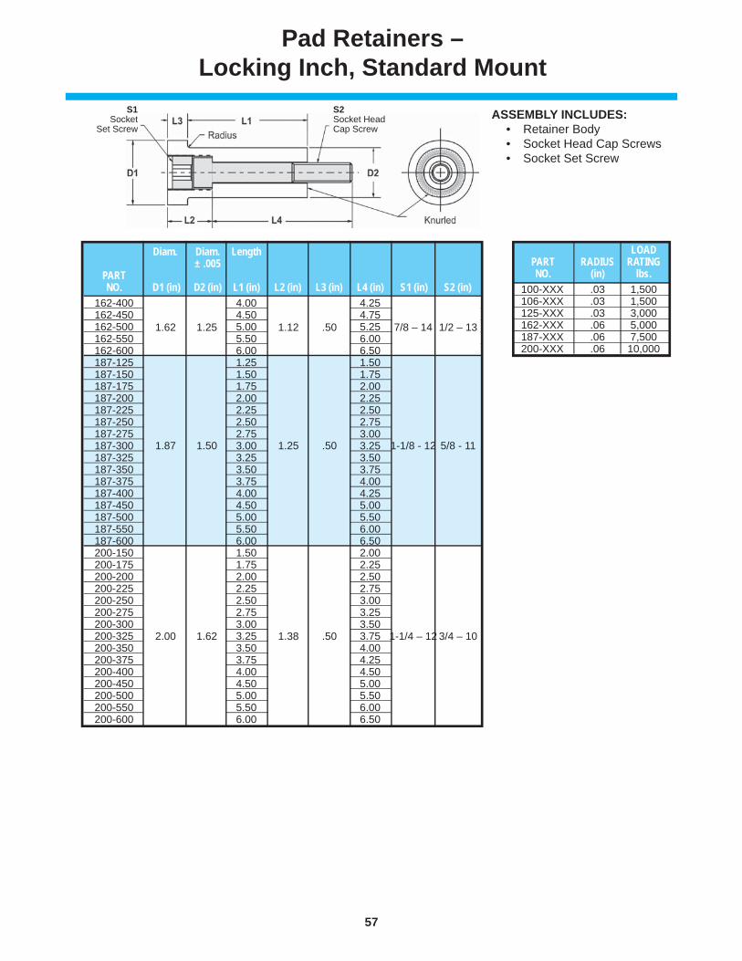
57
www.danly.com
Pad Retainers –Locking Inch, Standard Mount
ASSEMBLY INCLUDES: • Retainer Body • Socket Head Cap Screws • Socket Set Screw
Diam. Diam. Length ± .005 PART NO. D1 (in) D2 (in) L1 (in) L2 (in) L3 (in) L4 (in) S1 (in) S2 (in) 162-400 4.00 4.25 162-450 4.50 4.75 162-500 5.00 5.25 162-550 5.50 6.00 162-600 6.00 6.50 187-125 1.25 1.50 187-150 1.50 1.75 187-175 1.75 2.00 187-200 2.00 2.25 187-225 2.25 2.50 187-250 2.50 2.75 187-275 2.75 3.00 187-300 3.00 3.25 187-325 3.25 3.50 187-350 3.50 3.75 187-375 3.75 4.00 187-400 4.00 4.25 187-450 4.50 5.00 187-500 5.00 5.50 187-550 5.50 6.00 187-600 6.00 6.50 200-150 1.50 2.00 200-175 1.75 2.25 200-200 2.00 2.50 200-225 2.25 2.75 200-250 2.50 3.00 200-275 2.75 3.25 200-300 3.00 3.50 200-325 3.25 3.75 200-350 3.50 4.00 200-375 3.75 4.25 200-400 4.00 4.50 200-450 4.50 5.00 200-500 5.00 5.50 200-550 5.50 6.00 200-600 6.00 6.50
1.62 1.25 1.12 .50 7/8 – 14 1/2 – 13
1.87 1.50 1.25 .50 1-1/8 - 12 5/8 - 11
1.25 1.00 1.12 .50 3/4 – 16 3/8 – 16
2.00 1.62 1.38 .50 1-1/4 – 12 3/4 – 10
LOAD PART RADIUS RATING NO. (in) lbs.100-XXX .03 1,500106-XXX .03 1,500125-XXX .03 3,000162-XXX .06 5,000187-XXX .06 7,500200-XXX .06 10,000
S1Socket
Set Screw
S2Socket HeadCap Screw

58
www.danly.com
Pad Retainers –Locking Inch, Standard Mount with Flats
Pad retainers are manufactured from 1144 steel and hardened to 28-34 Rockwell C-scale. They are machined to precise tolerances in order to retain the pad and assure parallelism during use. The NP Series is also available, by special order, that offers three prongs as opposed to knurl.
125-250F
Product Features
Diam. Diam. Length ± .005 PART NO. D1 (in) D2 (in) L1 (in) L2 (in) L3 (in) L4 (in) S1 (in) S2 (in) 100-100F 1.00 1.00 100-125F 1.25 1.25 100-150F 1.50 1.50 100-175F 1.75 1.75 100-200F 2.00 2.00 100-225F 1.00 .75 2.25 1.00 .38 2.25 5/8 - 18 5/16 - 18 100-250F 2.50 2.50 100-275F 2.75 2.75 100-300F 3.00 3.00 100-325F 3.25 3.25 100-350F 3.50 3.50 106-100F 1.00 1.00 106-125F 1.25 1.25 106-150F 1.50 1.50 106-175F 1.75 1.75 106-200F 2.00 2.00 106-225F 1.06 .81 2.25 1.00 .375 2.25 5/8 – 18 5/16 – 18 106-250F 2.50 2.50 106-275F 2.75 2.75 106-300F 3.00 3.00 106-325F 3.25 3.25 106-350F 3.50 3.50 125-100F 1.00 1.00 125-125F 1.25 1.25 125-150F 1.50 1.50 125-175F 1.75 1.75 125-200F 2.00 2.00 125-225F 2.25 2.25 125-250F 2.50 2.50 125-275F 2.75 2.75 125-300F 1.25 1.00 3.00 1.12 .50 3.00 3/4 - 16 3/8 - 16 125-325F 3.25 3.25 125-350F 3.50 3.50 125-375F 3.75 3.75 125-400F 4.00 4.00 125-450F 4.50 4.50 125-500F 5.00 5.00 125-550F 5.50 5.50 125-600F 6.00 6.00 162-100F 1.00 1.25 162-125F 1.25 1.50 162-150F 1.50 1.75 162-175F 1.75 2.00 162-200F 2.00 2.25 162-225F 2.25 2.50 162-250F 2.50 2.75 162-275F 2.75 3.00 162-300F 3.00 3.25 162-325F 3.25 3.50 162-350F 3.50 3.75 162-375F 3.75 4.00
1.00 .75 1.00 .38 5/8 – 18 5/16 – 18
1.06 .81 1.00 .375 5/8 - 18 5/16 – 18
1.25 1.00 1.12 .50 3/4 – 16 3/8 – 16
1.62 1.25 1.12 .50 7/8 – 14 1/2 – 13

59
www.danly.com
Pad Retainers –Locking Inch, Standard Mount with Flats
ASSEMBLY INCLUDES: • Retainer Body • Socket Head Cap Screws • Socket Set Screw
Diam. Diam. Length ± .005 PART NO. D1 (in) D2 (in) L1 (in) L2 (in) L3 (in) L4 (in) S1 (in) S2 (in) 162-400F 4.00 4.25 162-450F 4.50 4.75 162-500F 5.00 5.25 162-550F 5.50 6.00 162-600F 6.00 6.50 187-125F 1.25 1.50 187-150F 1.50 1.75 187-175F 1.75 2.00 187-200F 2.00 2.25 187-225F 2.25 2.50 187-250F 2.50 2.75 187-275F 2.75 3.00 187-300F 3.00 3.25 187-325F 3.25 3.50 187-350F 3.50 3.75 187-375F 3.75 4.00 187-400F 4.00 4.25 187-450F 4.50 5.00 187-500F 5.00 5.50 187-550F 5.50 6.00 187-600F 6.00 6.50 200-150F 1.50 2.00 200-175F 1.75 2.25 200-200F 2.00 2.50 200-225F 2.25 2.75 200-250F 2.50 3.00 200-275F 2.75 3.25 200-300F 3.00 3.50 200-325F 3.25 3.75 200-350F 3.50 4.00 200-375F 3.75 4.25 200-400F 4.00 4.50 200-450F 4.50 5.00 200-500F 5.00 5.50 200-550F 5.50 6.00 200-600F 6.00 6.50
1.62 1.25 1.12 .50 7/8 – 14 1/2 – 13
1.87 1.50 1.25 .50 1-1/8 - 12 5/8 – 11
1.25 1.00 1.12 .50 3/4 – 16 3/8 – 16
2.00 1.62 1.38 .50 1-1/4 – 12 3/4 – 10
S1Socket
Set Screw
S2Socket HeadCap Screw
LOAD PART F RADIUS RATING NO. (in) (in) lbs.100-XXX .625 .03 1,500106-XXX .690 .03 1,500125-XXX .875 .03 3,000162-XXX 1.125 .06 5,000187-XXX 1.250 .06 7,500200-XXX 1.375 .06 10,000

60
www.danly.com
Pad Retainers –Locking Inch, Standard Mount with Flats
125-250R
Pad retainers are manufactured from 1144 steel and hardened to 28-34 Rockwell C-scale. They are machined to precise tolerances in order to retain the pad and assure parallelism during use.
Product Features
Diam. Diam. Length ± .005 PART NO. D1 (in) D2 (in) L1 (in) G (in) L3 (in) T1 (in) 100-100R 1.00100-125R 1.25100-150R 1.50100-175R 1.75100-200R 2.00100-225R 2.25100-250R 2.50100-275R 2.75100-300R 3.00100-350R 3.50100-375R 3.75100-400R 4.00100-450R 4.50100-500R 5.00100-550R 5.50100-600R 6.00106-100R 1.00 106-125R 1.25106-150R 1.50106-175R 1.75106-200R 2.00106-225R 2.25106-250R 2.50106-275R 2.75106-300R 3.00106-325R 3.25106-350R 3.50125-100R 1.00125-125R 1.25125-150R 1.50125-175R 1.75125-200R 2.00125-225R 2.25125-250R 2.50125-275R 2.75125-300R 3.00125-325R 3.25125-350R 3.50125-375R 3.75125-400R 4.00125-450R 4.50125-500R 5.00125-550R 5.50125-600R 6.00
1.00 .75 .625 .38 5/16 – 18
1.06 .81 .625 .38 5/16 - 18
1.25 1.00 .750 .50 3/8 – 16
Diam. Diam. Length ± .005 PART NO. D1 (in) D2 (in) L1 (in) G (in) L3 (in) T1 (in) 100-125R 1.25162-150R 1.50 162-175R 1.75162-200R 2.00162-225R 2.25162-250R 2.50162-275R 2.75162-300R 3.00162-325R 3.25162-350R 3.50162-375R 3.75162-400R 4.00162-450R 4.50162-500R 5.00162-550R 5.50162-600R 6.00187-150R 1.50187-175R 1.75187-200R 2.00187-225R 2.25 187-250R 2.50187-275R 2.75187-300R 3.00187-325R 3.25187-350R 3.50187-375R 3.75187-400R 4.00187-450R 4.50187-500R 5.00187-550R 5.50187-600R 6.00200-175R 1.75200-200R 2.00200-225R 2.25 200-250R 2.50 200-275R 2.75 200-300R 3.00 200-325R 3.25 200-350R 3.50 200-375R 3.75 200-400R 4.00 200-450R 4.50 200-500R 5.00 200-550R 5.50 200-600R 6.00
1.62 1.25 1.000 .50 1/2 – 13
1.87 1.50 1.250 .50 5/8 – 11
2.00 1.62 1.500 .50 3/4 – 10
LOAD PART F RADIUS RATING NO. (in) (in) lbs.100-XXXR .625 .03 1,500106-XXXR .690 .03 1,500125-XXXR .875 .03 3,000162-XXXR 1.125 .06 5,000187-XXXR 1.250 .06 7,500200-XXXR 1.375 .06 10,000
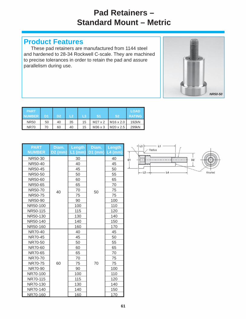
61
www.danly.com
These pad retainers are manufactured from 1144 steel and hardened to 28-34 Rockwell C-scale. They are machined to precise tolerances in order to retain the pad and assure parallelism during use.
Product Features
Pad Retainers –Standard Mount – Metric
NR50-50
NR50-30 30 40 NR50-40 40 45 NR50-45 45 50 NR50-50 50 55 NR50-60 60 65 NR50-65 65 70 NR50-70 70 75 NR50-75 75 75 NR50-90 90 100 NR50-100 100 110 NR50-115 115 120 NR50-130 130 140 NR50-140 140 150 NR50-160 160 170 NR70-40 40 45 NR70-45 45 50 NR70-50 50 55 NR70-60 60 65 NR70-65 65 70 NR70-70 70 75 NR70-75 75 75 NR70-90 90 100 NR70-100 100 110 NR70-115 115 120 NR70-130 130 140 NR70-140 140 150 NR70-160 160 170
PART Diam. Length Diam. Length NUMBER D2 (mm) L1 (mm) D1 (mm) L4 (mm)
40 50
60 70
PART LOAD NUMBER D1 D2 L2 L3 S1 S2 RATING NR50 50 40 35 15 M27 x 2 M16 x 2.0 192kN NR70 70 60 40 15 M36 x 3 M20 x 2.5 299kN

62
www.danly.com
Pad Retainers –Reverse Mount – Metric
NR50-50R
These pad retainers are manufactured from 1144 steel and hardened to 28-34 Rockwell C-scale. They are machined to precise tolerances in order to retain the pad and assure parallelism during use.
Product Features
NR50-30R 30 NR50-40R 40 45 NR50-45R 45 NR50-50R 50 55 NR50-60R 60 NR50-65R 65 NR50-70R 70 NR50-75R 75 NR50-90R 90 NR50-100R 100 NR50-115R 115 NR50-130R 130 NR50-140R 140 NR50-160R 160 NR70-40R 40 NR70-45R 45 NR70-50R 50 NR70-60R 60 NR70-65R 65 NR70-70R 70 NR70-75R 75 NR70-90R 90 NR70-100R 100 NR70-115R 115 NR70-130R 130 NR70-140R 140 NR70-160R 160
PART Diam. Length Diam. T1 NUMBER D2 (mm) L1 (mm) D1 (mm) (mm)
40 50 M16 x 2.0
60 70 M20 x 2.5
PART LOAD NUMBER D1 D2 F L3 RATING NR50 50 40 33.65 15 192kN NR70 70 60 53.70 15 299kN

WEAR PRODUCTS
The IEM Value Proposition I. IEM is recognized as the leader in manufacturing quality die components to the global parts forming industry. Our reputation has been built by satisfying customer needs, and we are very strong in the automotive and appliance industries.
II. IEM offers outstanding delivery on a consistent basis. Choosing us as a supplier means that our customers have a competitive advantage in delivering their products to the market.
III. IEM has complex machining capabilities on die components at several facilities. With extensive machining capabilities in the USA and China, we have taken the lead role in creating and bringing new products to customers and helping them fi nd solutions that improve their operations.
IV. IEM’s vast breadth of products assures innovative solutions. We strive to address customer problems by utilizing our research and development department as well as other technical professionals.
V. IEM has a technically trained sales force and distributor channels with Engineering support. Sales, Marketing and Engineering professionals are available to support our product lines.
...A LEADING MANUFACTURER AND INNOVATOR OF DIE COMPONENTS SUPPLIED GLOBALLY TO THE METAL
FORMING INDUSTRY...
Competitive PricesReliability and Performance
High Quality Design & ConstructionOutstanding Service & Support

WEAR PRODUCTS
© 2013 IEM. All rights reserved. 560-6 (W) 8/13
Distributed by:
a MISUMI Group Company
Anchor Lamina America, [email protected]
WITHIN THE USA & CANADACALL: 800-652-6462FAX: 800-406-4410
OUTSIDE THE USA & CANADACALL: 001-248-489-9122FAX: 001-248-553-6842