install manual/service letter - kelly aerospace rev d - 182t and t1… · amm and all applicable...
TRANSCRIPT

NC-08-006 182T, T182T AIR CONDITIONING INSTALLATION
Page 1 of 19 Kelly Aerospace cannot be responsible for the quality of work performed by others while fulfilling the requirements of this Service Letter. Procedures specified in this Service Letter must be accomplished with the standards and techniques set forth in the approved AMM and all applicable government regulations, standards and advisories. All processes and material information referenced within this Service Letter is derived from Kelly Aerospace Thermal Systems FAA approved specifications.
1625 Lost Nation Rd. , Willoughby, OH 44094 PH: 440-951-4744 FAX:440-951-4725
Install manual/Service Letter
Doc No: NC-08-006 Rev D
Issue Date: 16 May 2008
EFFECTIVITY
Cessna Aircraft Types: 182T, T182T
REVISION HISTORY
REV DESCRIPTION DATE
B Changed format, additional clarifications 17 Sept 2008 C See ECN #09-052 15 May 2009 D See ECN #09-050 11 June 2009

NC-08-006 182T, T182T AIR CONDITIONING INSTALLATION
Page 2 of 19 Kelly Aerospace cannot be responsible for the quality of work performed by others while fulfilling the requirements of this Service Letter. Procedures specified in this Service Letter must be accomplished with the standards and techniques set forth in the approved AMM and all applicable government regulations, standards and advisories. All processes and material information referenced within this Service Letter is derived from Kelly Aerospace Thermal Systems FAA approved specifications.
TABLE OF CONTENTS
EFFECTIVITY ................................................................................................................... 1
REVISION HISTORY........................................................................................................ 1
TABLE OF CONTENTS .................................................................................................... 2
TABLE OF FIGURES ........................................................................................................ 3
TABLE OF TABLES ......................................................................................................... 3
PURPOSE ........................................................................................................................... 3
COMPLIANCE................................................................................................................... 3
APPROVAL ....................................................................................................................... 3
RESOURCES ..................................................................................................................... 3
SYSTEM OVERVIEW ...................................................................................................... 4
MATERIAL INFORMATION ........................................................................................... 4
INSTRUCTIONS FOR COMPLIANCE ............................................................................ 5
1. Preparation ............................................................................................................... 5
2. Installation of components ....................................................................................... 6
3. Modification of existing components .................................................................... 16
4. Wiring .................................................................................................................... 16
5. Servicing ................................................................................................................ 17
6. Reassembly of aircraft ........................................................................................... 18
7. Perform operational tests of air conditioning system. ........................................... 18
8. Return to service .................................................................................................... 19

NC-08-006 182T, T182T AIR CONDITIONING INSTALLATION
Page 3 of 19 Kelly Aerospace cannot be responsible for the quality of work performed by others while fulfilling the requirements of this Service Letter. Procedures specified in this Service Letter must be accomplished with the standards and techniques set forth in the approved AMM and all applicable government regulations, standards and advisories. All processes and material information referenced within this Service Letter is derived from Kelly Aerospace Thermal Systems FAA approved specifications.
TABLE OF FIGURES
Figure 1 – Condenser / Compressor Plenum Installation ................................................... 7
Figure 2 – Condenser Fan Installation ................................................................................ 7
Figure 3 – Condenser Fan Relay ......................................................................................... 8
Figure 4 – Cannon Plug Condenser Plenum Pass Through. ............................................... 8
Figure 5 – Condenser Plenum Installation. View from Baggage Compartment. ............... 9
Figure 6 – Suggested Installation Location of Climate Controller ..................................... 9
Figure 7 - Blue dot is a typical piezo electric switch installation. .................................... 10
Figure 8 - Aft most drain (top of picture) line is typical evaporator drain installation..... 11 Figure 9 – Approximate location of 60 amp shunt, .......................................................... 12
Figure 10 – Location of firewall feed through. ................................................................ 13
Figure 11 – Ducting and Headliner ................................................................................... 15
Figure 12 – Air Vent Installation ...................................................................................... 15
Figure 13 – R-134a Hose Layout ...................................................................................... 17
TABLE OF TABLES
Table 1 – Torque Specifications ......................................................................................... 6
PURPOSE
For installation of air conditioning system
COMPLIANCE
Not mandatory, shall be complied with at aircraft owner’s discretion
APPROVAL
FAA approval has been obtained on all technical data in this Service Letter that affects type design.
RESOURCES
100 hours of labor are required to comply with this Service Letter.

NC-08-006 182T, T182T AIR CONDITIONING INSTALLATION
Page 4 of 19 Kelly Aerospace cannot be responsible for the quality of work performed by others while fulfilling the requirements of this Service Letter. Procedures specified in this Service Letter must be accomplished with the standards and techniques set forth in the approved AMM and all applicable government regulations, standards and advisories. All processes and material information referenced within this Service Letter is derived from Kelly Aerospace Thermal Systems FAA approved specifications.
SYSTEM OVERVIEW
The Cessna 182T/T182T is a single alternator, single bus electrical system. The existing system uses an ASG12000-3 / 9910592-3, 95 amp alternator, which is mounted on the right front side below the engine cooling baffling. The Air Conditioning System is powered by the primary alternator. Some load shedding is required when running the air conditioning system. Refer to the AFMS for the electrical load limitations The air conditioning system consists of an electric hermetically sealed compressor, condenser and evaporator all located on or behind the hat rack. The system is operated through temperature selection on a climate controller located on the right side of the instrument panel. There is both a fan mode only and a cooling mode. R-134a is used as a refrigerant for the system. All R-134a lines are located at or behind the hat rack. Power is run from the second alternator under the floor to the components in the rear of the aircraft. A toggle switch near the climate controller is used to turn the system on and off.
MATERIAL INFORMATION
The following documents list the materials required for compliance with this Service Letter. Parts can be obtained from Kelly Aerospace Thermal Systems (Kats), or procured locally (P/L) as indicated
NC-08-039 (KATS) 182T Misc hardware List (P/L)

NC-08-006 182T, T182T AIR CONDITIONING INSTALLATION
Page 5 of 19 Kelly Aerospace cannot be responsible for the quality of work performed by others while fulfilling the requirements of this Service Letter. Procedures specified in this Service Letter must be accomplished with the standards and techniques set forth in the approved AMM and all applicable government regulations, standards and advisories. All processes and material information referenced within this Service Letter is derived from Kelly Aerospace Thermal Systems FAA approved specifications.
INSTRUCTIONS FOR COMPLIANCE
1. Preparation
A. Insure all documentation is the latest revision. B. Conduct a parts inventory to insure all required items are present. C. Remove aircraft battery per the Cessna Aircraft Maintenance Manual (AMM) D. Remove the engine cowling per (AMM) E. Secure external power receptacle to prevent unwanted power on aircraft busses (e.g. tape
over receptacle with non metallic masking tape with label warning of hazard.) F. Remove the following components utilizing the AMM and store securely:
1) Front and rear seats 2) Headliner to include upper aft window molding left and right, and left and right aft
passenger window molding. 3) Remove left and right former from overhead and discard. 4) Hat rack close out panels and carpet 5) Cabin carpet 6) Tail cone avionics access panel 7) ELT and antenna coax 8) Aft black plastic close out 9) Glove box 10) LH rudder pedal cover 11) Floor inspection panels when/as required 12) Lamar electrical box cover 13) T182T ONLY
a. Exhaust pipe and waste gate (T182T ONLY) b. O2 bottle (T182T ONLY) c. O2 bottle fwd mount brackets and both band clamps d. Aft passenger O2 outlets and supply lines
G. For all references to wire stripping, crimping and tying procedures refer to AC 43.13-1B chapter 11
H. For all references to riveting procedures refer to AC 43.13-1B chapter 4

NC-08-006 182T, T182T AIR CONDITIONING INSTALLATION
Page 6 of 19 Kelly Aerospace cannot be responsible for the quality of work performed by others while fulfilling the requirements of this Service Letter. Procedures specified in this Service Letter must be accomplished with the standards and techniques set forth in the approved AMM and all applicable government regulations, standards and advisories. All processes and material information referenced within this Service Letter is derived from Kelly Aerospace Thermal Systems FAA approved specifications.
I. Torque Specifications
Unless otherwise specified, use the following torque values. 6-32 UNC 7-9 inch-lbs 8-32 UNC 17-19 inch-lbs 10-24 UNC 20-22 inch-lbs 10-32 UNF 28-31 inch-lbs 1/4-20 UNC 70-75 inch-lbs 1/4-28 UNF 90-94 inch-lbs 5/16-24 UNF 220-230 inch-lbs 3/8-24 UNF 445-455 inch-lbs 7/16-20 UNF 760-780 inch-lbs
Table 1 – Torque Specifications
2. Installation of components
A. Existing aircraft rivets will need to be removed as required to attach ELT bracket, circuit breaker bracket and condenser/compressor assembly. Reinstallation with longer rivets may be required.
B. Remove ELT mounting bracket from left tail cone 1) Remove buzzer mount from ELT bracket and mount on new ELT bracket AC-
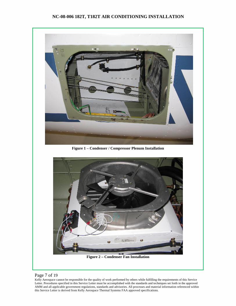
00120 per Dwg# AC-00146 C. Install bracket AC-00120 Per Dwg# AC-00146 D. Install Condenser/Compressor Assembly per Dwg # AC-00080 and Figure 1 through
Figure 5 below.
NC-08-006 182T, T182T AIR CONDITIONING INSTALLATION
Page 7 of 19 Kelly Aerospace cannot be responsible for the quality of work performed by others while fulfilling the requirements of this Service Letter. Procedures specified in this Service Letter must be accomplished with the standards and techniques set forth in the approved AMM and all applicable government regulations, standards and advisories. All processes and material information referenced within this Service Letter is derived from Kelly Aerospace Thermal Systems FAA approved specifications.
Figure 1 – Condenser / Compressor Plenum Installation
Figure 2 – Condenser Fan Installation

NC-08-006 182T, T182T AIR CONDITIONING INSTALLATION
Page 8 of 19 Kelly Aerospace cannot be responsible for the quality of work performed by others while fulfilling the requirements of this Service Letter. Procedures specified in this Service Letter must be accomplished with the standards and techniques set forth in the approved AMM and all applicable government regulations, standards and advisories. All processes and material information referenced within this Service Letter is derived from Kelly Aerospace Thermal Systems FAA approved specifications.
Figure 3 – Condenser Fan Relay
Figure 4 – Cannon Plug Condenser Plenum Pass Through.

NC-08-006 182T, T182T AIR CONDITIONING INSTALLATION
Page 9 of 19 Kelly Aerospace cannot be responsible for the quality of work performed by others while fulfilling the requirements of this Service Letter. Procedures specified in this Service Letter must be accomplished with the standards and techniques set forth in the approved AMM and all applicable government regulations, standards and advisories. All processes and material information referenced within this Service Letter is derived from Kelly Aerospace Thermal Systems FAA approved specifications.
Figure 5 – Condenser Plenum Installation. View from Baggage Compartment.
E. Install Evaporator Support Assembly reference Dwg # AC-00108 F. Mount Cabin temp sensor in AC-00090 as detailed in Dwg# AC-00108 sheet 2 view A-A G. Install circuit breaker bracket AC-00106 per Dwg# AC-00142 H. Reference Figure 6 below for suggested location of A1235
Figure 6 – Suggested Installation Location of Climate Controller

NC-08-006 182T, T182T AIR CONDITIONING INSTALLATION
Page 10 of 19 Kelly Aerospace cannot be responsible for the quality of work performed by others while fulfilling the requirements of this Service Letter. Procedures specified in this Service Letter must be accomplished with the standards and techniques set forth in the approved AMM and all applicable government regulations, standards and advisories. All processes and material information referenced within this Service Letter is derived from Kelly Aerospace Thermal Systems FAA approved specifications.
I. Install referencing Dwg# A1235 for dimensions.
1) Insure chosen location has adequate clearance behind panel for wiring harness loop 2) Providing careful measurement and adequate panel thickness will allow for the
instrument panel to be tapped to 4-40 screw threads and the A1235 simply screwed in to the panel.
J. Drill holes for external piezo electric switch and evaporator drain line where required. Figure 7 and Figure 8 show typical installations.
Figure 7 - Blue dot is a typical piezo electric switch installation.

NC-08-006 182T, T182T AIR CONDITIONING INSTALLATION
Page 11 of 19 Kelly Aerospace cannot be responsible for the quality of work performed by others while fulfilling the requirements of this Service Letter. Procedures specified in this Service Letter must be accomplished with the standards and techniques set forth in the approved AMM and all applicable government regulations, standards and advisories. All processes and material information referenced within this Service Letter is derived from Kelly Aerospace Thermal Systems FAA approved specifications.
Figure 8 - Aft most drain (top of picture) line is typical evaporator drain installation.
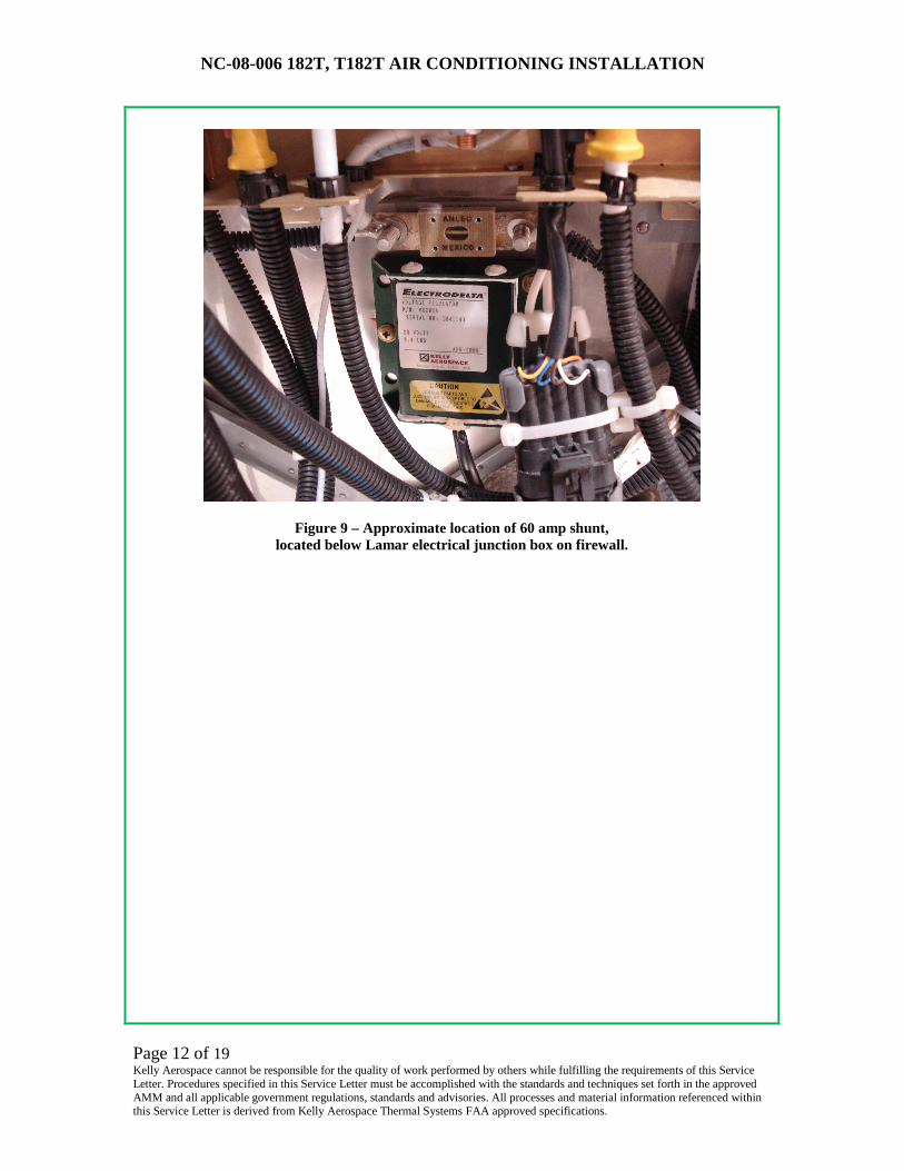
K. Drill holes and mount the following components on the firewall with MS21059L3K #10 nut plates and monel rivets. Reference Figure 9 below for details
NOTE:
Be sure selected locations for installation of components on firewall have adequate clearance for installation tools on both sides of firewall.
(E.g. clearance from engine mounts for rivet gun and room inside cabin for bucking bar around rudder pedals.)
1) 60 Amp current limiter (Lee air P/N 76655-1) 2) Firewall feed through (2150903-5)
NC-08-006 182T, T182T AIR CONDITIONING INSTALLATION
Page 12 of 19 Kelly Aerospace cannot be responsible for the quality of work performed by others while fulfilling the requirements of this Service Letter. Procedures specified in this Service Letter must be accomplished with the standards and techniques set forth in the approved AMM and all applicable government regulations, standards and advisories. All processes and material information referenced within this Service Letter is derived from Kelly Aerospace Thermal Systems FAA approved specifications.
Figure 9 – Approximate location of 60 amp shunt, located below Lamar electrical junction box on firewall.

NC-08-006 182T, T182T AIR CONDITIONING INSTALLATION
Page 13 of 19 Kelly Aerospace cannot be responsible for the quality of work performed by others while fulfilling the requirements of this Service Letter. Procedures specified in this Service Letter must be accomplished with the standards and techniques set forth in the approved AMM and all applicable government regulations, standards and advisories. All processes and material information referenced within this Service Letter is derived from Kelly Aerospace Thermal Systems FAA approved specifications.
Figure 10 – Location of firewall feed through.
L. O2 bottle relocation (T182T only) WARNING:
Do not let oil, grease, or other lubricants near high pressure oxygen because it can cause a fire. Do not smoke or have an open flame in or near the
airplane while you work on the oxygen system.
1) The O2 bottle will need to be relocated due to its location and where the condenser plenum assembly is installed.
2) Utilize Chapter 35 of the Cessna 182T/T182 Maintenance manual for removal of oxygen components.
3) Remove oxygen system aft of T fitting AN824-5D located in the overhead depicted in Detail A of Figure 201 Cessna MM 35-01-00 page 203 Jul 3/2006.
4) If aircraft is T18208150 and on remove the 4 brackets that the O2 bottle clamps loop through. Two of these will be reused later in the bottle relocation.
5) If aircraft is T18208001 thru T18208149 you will need to order the brackets detailed above.
a. See Cessna 182/T182 IPC 35-20-00 Figure 1 (sheet 2) page 2 Jul 1/2007

NC-08-006 182T, T182T AIR CONDITIONING INSTALLATION
Page 14 of 19 Kelly Aerospace cannot be responsible for the quality of work performed by others while fulfilling the requirements of this Service Letter. Procedures specified in this Service Letter must be accomplished with the standards and techniques set forth in the approved AMM and all applicable government regulations, standards and advisories. All processes and material information referenced within this Service Letter is derived from Kelly Aerospace Thermal Systems FAA approved specifications.
6) Save all hardware from oxygen installation for later use. (Bottle clamps and
brackets, line clamps, fill line ect.)
WARNING: CAP ALL LINES IMMEDIATELY WITH CLEAN CAPS.
7) See Dwg # AC-00149 for overall installation illustration. 8) Forward and aft edges of O2 box will be aligned with FS 92.0 and FS 124.0
respectively. FS 110.0 will also be an attach point and will be located on the top flange of the box when installed in the aircraft.
9) See Dwg# AC-00130 for oxygen bottle box construction. The box utilizes typical aircraft sheet metal construction techniques.
10) Between FS 92.0 and FS 110.0 the two brackets removed from the tail cone or ordered previously will be riveted in using existing rivet locations along the fuselage.
11) Bracket supplied with the kit will be located aft of FS 110.0 and fit as required. The Black delrin block may be modified to allow for a better fit of bracket to bottle. (Reliefs in the bottom of the block may be required as well to clear rivets.) Bracket is secured with 2 AN4-11A bolts and 2 AN970-4 large area washers under the baggage floor with MS21044N08 lock nut.
12) Some small adjustments may be required on individual installations to include but not limited to, bending oxygen lines for best fit, clamping lines and final oxygen bottle and box cover locations.
M. Headliner
1) The old headliner will be replaced with a new headliner and internal ducting. Installation of headliner typically occurs after all other tasks have been accomplished and system is serviced but prior to the rest of the cabin interior reinstallation.
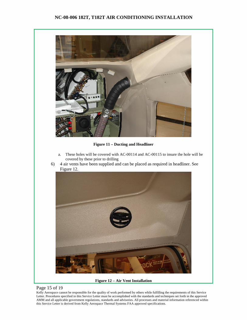
2) Install new headliner AC-00120 with reference to old headliner installation. 3) Additional screws may be required to achieve a good fit 4) Reinstall all panels and hardware as required from removed headliner 5) 2.5 inch holes will need to be cut in the existing headliner over the hat rack for the
conditioned air hose to be routed forward through. See Figure 11.
NC-08-006 182T, T182T AIR CONDITIONING INSTALLATION
Page 15 of 19 Kelly Aerospace cannot be responsible for the quality of work performed by others while fulfilling the requirements of this Service Letter. Procedures specified in this Service Letter must be accomplished with the standards and techniques set forth in the approved AMM and all applicable government regulations, standards and advisories. All processes and material information referenced within this Service Letter is derived from Kelly Aerospace Thermal Systems FAA approved specifications.
Figure 11 – Ducting and Headliner
a. These holes will be covered with AC-00114 and AC-00115 to insure the hole will be covered by these prior to drilling
6) 4 air vents have been supplied and can be placed as required in headliner. See Figure 12.
Figure 12 – Air Vent Installation

NC-08-006 182T, T182T AIR CONDITIONING INSTALLATION
Page 16 of 19 Kelly Aerospace cannot be responsible for the quality of work performed by others while fulfilling the requirements of this Service Letter. Procedures specified in this Service Letter must be accomplished with the standards and techniques set forth in the approved AMM and all applicable government regulations, standards and advisories. All processes and material information referenced within this Service Letter is derived from Kelly Aerospace Thermal Systems FAA approved specifications.
3. Modification of existing components
A. Modify tail cone access door per Dwg# AC-00111 B. Assemble tail cone access door per Dwg# AC-00109 C. Modify T182 skin and assemble the plenum inlet on T182 or T182T per Dwg# AC-
00241, the AC-00240 inlet scoop is optional, and may be required in the hot climates. D. T182T only
1) Remove left engine inlet naca scoop and repair per Cessna Structural Repair Manual (SRM)
2) Install flange 10350-12 per Dwg # AC-00136 on lower left cowling. 3) Trim to fit supplied 3 in. Scat tubing to route air to the heat muff and secure as
required.(reuse hose clamps) 4) High Temp RTV may be used to buffer the scat hose from the alternator if rubbing
is expected. E. Paint reworked areas per AMM as required. F. Trim original hat rack close outs to allow ease of maintenance and still block
unconditioned air from entering cabin, typically cutting the original hat rack back wall close out into two pieces. One will cover from the aircraft right side to about 2/3 of the way with a cut vertically so that the remaining 1/3 may be removed as required for maintenance. The split created by the vertical cut will allow the AC lines access to the evaporator assembly. The 1/3 piece should be drilled to match the circuit breaker bracket so that the breakers may be seen when panel AC-00113 is removed. Sealing of these panels with tape is recommended.
G. Remove ELT placard and reinstall on AC-00113 H. Trim hat rack carpet as required to fit around AC-00090 evaporator support assy. I. Attaching brackets AC-00143 to headliner above hat rack can be done with screws and
nuts or rivets so that AC-00113 can be installed by simply Velcro fasteners or sheet metal screws through AC-00113 to AC-00143.
4. Wiring
A. A1235 controller wiring harness AC-00099 1) All harness runs below the cabin floor should be inside conduit. 2) A1235 harness runs from copilot’s instrument panel to the left aft tailcone by
following the existing wiring bundles and crossing over the center line of the aircraft under the avionics/hat rack area.
3) INSURE NO CONTROL CABLE INTERFERANCE 4) Sufficient wire bundle length has been provided to accommodate variations in wire
routing. 5) Terminate harness per Dwg# AC-00098 6) See Dwg# AC-00089 for detail

NC-08-006 182T, T182T AIR CONDITIONING INSTALLATION
Page 17 of 19 Kelly Aerospace cannot be responsible for the quality of work performed by others while fulfilling the requirements of this Service Letter. Procedures specified in this Service Letter must be accomplished with the standards and techniques set forth in the approved AMM and all applicable government regulations, standards and advisories. All processes and material information referenced within this Service Letter is derived from Kelly Aerospace Thermal Systems FAA approved specifications.
B. Lamar box interface
CAUTION:
All wiring added inside Lamar box will be wrapped with spiral wrap and secured where required to insure wires are protected from chaffing,
sharp bends ect. Wires exiting the Lamar box will be protected with snap bushings in open spaces. Care is to be taken in routing wires so as to
avoid overcrowding, this may require wiring to be routed behind relays ect.
1) See Dwg# AC-00089 for wiring details
C. Compressor controller harness AC-00101
1) Install in condenser/compressor plenum as shown in Dwg# AC-00080 with items 16, 20 and 27
2) See Dwg# AC-00089 for detail D. External power harness AC-00067
1) See Dwg# AC-00089 for detail E. See Dwg# AC-00089 for all other wiring details
5. Servicing
A. Only qualified personnel with proper equipment may service this air conditioning system.
B. Connect condenser, evaporator, and compressor hoses part numbers 2233501, 2233505, 2233507 per Figure 13 below.
Figure 13 – R-134a Hose Layout

NC-08-006 182T, T182T AIR CONDITIONING INSTALLATION
Page 18 of 19 Kelly Aerospace cannot be responsible for the quality of work performed by others while fulfilling the requirements of this Service Letter. Procedures specified in this Service Letter must be accomplished with the standards and techniques set forth in the approved AMM and all applicable government regulations, standards and advisories. All processes and material information referenced within this Service Letter is derived from Kelly Aerospace Thermal Systems FAA approved specifications.
C. Wrap lines where required to prevent sweating with cork insulation tape P/N 4217-W3. D. Evacuate system and insure no system leakage prior to charging with R-134a. E. Charge system with 34 oz +/- 2 oz of R-134a.
6. Reassembly of aircraft
A. Reinstall the following components utilizing the AMM. 1) Front and rear seats 2) Cabin carpet 3) Tail cone avionics access panel 4) Aft black plastic close out trim as required 5) Glove box 6) LH rudder pedal cover 7) Floor inspection panels when/as required 8) Lamar electrical box cover 9) ELT and antenna coax 10) Exhaust pipe and waste gate (T182T ONLY)
B. Reinstall aircraft battery per the Cessna Aircraft Maintenance Manual (AMM) C. Reinstall the engine cowling per (AMM)
NOTE: Cabin heat air has been relocated on T182T to Flange installed on lower cowl.
Install with original hose clamps.
7. Perform operational tests of air conditioning system.
A. Plug in external power and energize B. Ensure cabin temp controller master switch is in the on position. C. Cabin temp should be displayed D. Select fans up and fan speed should correspond. E. Select fans “zero” fans should stop. F. Select ac “on” and drive cabin temp requested below ambient temp by at least 10 degrees
F. G. Headliner outlets should flow air 20-30 degrees cooler than ambient and fan speed will
increase to max. H. Deselect ac “on” leaving air conditioning master switch in the “on” position I. Cycle external power. J. Rub piezo electric switch located near the external power plug. K. Air conditioning should come on full cold and green ac annunciation will be flashing. L. Again headliner outlets should be 20-30 degrees cooler than ambient. M. Unplug external power and air conditioning will turn off. N. Check that water is coming from evaporator drain line, water will not be present only if
atmosphere is extremely dry, so if no water is flowing check for hose continuity to evaporator plenum. A steady stream of air should be felt at the evaporator drain line also as the evaporator fan pressurizes the plenum and forces condensed water out.

NC-08-006 182T, T182T AIR CONDITIONING INSTALLATION
Page 19 of 19 Kelly Aerospace cannot be responsible for the quality of work performed by others while fulfilling the requirements of this Service Letter. Procedures specified in this Service Letter must be accomplished with the standards and techniques set forth in the approved AMM and all applicable government regulations, standards and advisories. All processes and material information referenced within this Service Letter is derived from Kelly Aerospace Thermal Systems FAA approved specifications.
O. If any items do not operate as described, troubleshoot system and correct discrepancies. P. Aircraft will need to be located in a run up area to complete this section Q. Utilizing qualified personnel operate the aircraft engine per the Pilot Operating
Handbook. R. Repeat items b) through l) of this section to insure operation of the secondary alternator. S. If further assistance is needed contact Kelly Aerospace Thermal Systems Technical
support @ 440-951-4744
8. Return to service
A. Perform compass swing deviation check as required by AC 43.13-1B chpt12 sec3 B. Update aircraft Weight and Balance records. C. Install Approved Flight Manual Supplement D. Complete FAA form 337. E. Make aircraft log book entry