instruction manual and warranty
TRANSCRIPT

1x Super Pro Automatic, bike powered, logical mixing and control hub unit
1x Rider’s noise cancelling stereo headset with plug-in ambient noise sensor
1x Passenger’s noise cancelling stereo headset
2x Coiled headset extension leads
1x Deluxe bike fitting kit with on-bike socket holders and dust caps
1x Standard 2000mm phone leads
1x Standard 2000mm stereo music lead
INSTRUCTION MANUALand WARRANTY
It is very important that you fully read and understand all ofthese instructions before installation and use.
This system is designed for domestic motorcycle use only.
2015211021132138242221762245
Kit SP-A includes:
Kit SP-ASuper Pro Automatic
HUB
IMPORTANT NOTE:PLEASE ASK your supplier to personally check with you that this kit contains ALL the parts listedabove before you leave the shop!
Autocom UK has carefully checked that all of the parts listed above are supplied in this kit at thetime of packing and shipping; however we also train our suppliers to check and confirm with you (inthe shop) that you have all of these listed parts supplied in your kit before leaving the shop. Becauseof this thorough triple check quality control method Autocom UK cannot accept any claims formissing parts once you have left the shop.
This product is intended for sale ONLY from authorised retail premises by trained authorisedAutocom dealers, where your supplier has provided you with high quality hands on demonstrationand advice about the products before you purchase. This product is not to be sold/purchased viamail order etc or from any dealer who has not/or cannot provide you with high quality face to facehands on demonstration and after sales service and support.
If this product was supplied to you by mail order, we ask that you please [email protected] or telephone: +44 (0)1926 431249 and let us know who your supplierwas, such that we can ensure that ALL of our customers receive the highest standards of supply andsupport that our customers, products and brand deserves.
Please fill in and return the product registration on the inside back cover.
Super Pro Auto Instructions 8/5/09 2:24 pm Page 1
Thank you for choosing Autocom. Your Super Pro Automatic system is designed, built and fully testedto be the very best, and provide you with many years of very high quality use and performance ifinstalled and used as described in these instructions.
Please take the time to fully read and understand these instructions before installation and use and feelfree to ask your Autocom dealer for advice, or call our help-line if anything is not perfectly clear andunderstandable. Telephone: +44 (0)1926 431249 (UK). Email: [email protected]
It is very important to properly set up and use these products as designed. Please do not make anymodifications or try to use your system with any non recommended products or in any other way thandescribed. Do not cut or modify your helmets.
It is common sense and the law in some countries that the rider of a vehicle be in control at all times,which includes the ability to hear other road users warnings. As such the RIDER should not have themusic volume so loud as to prevent this. Safety should always be your first priority and is ultimatelythe responsibility of the rider. Make sure that the quick release connectors are free to quick release inthe event of an emergency. Do not fix or tape them together.
The rider should only make adjustments while stationary, never while in motion. Always focus yourattention to riding and safety and do not use the system in such a way as to interfere with this. Theadded ability to communicate between rider and passenger and/or with other riders on other bikes canconsiderably improve your safety, so become familiar with using the system to provide good adviceand/or warnings etc.
The Super Pro Automatic hub system supplied in Kit SP-A is designed for 12 volt bike powered use,providing unlimited duration and ultra high quality and performance. Hi-Fi quality stereo headsets withplug-in true noise cancelling boom microphones, rugged water resistant headset leads and connectors,5 Aux connections (4 of which are stereo) and options for a single or twin plug-in stereo remoteBluetooth module/s which can connect to between one and four wireless Bluetooth devices.
The innovative logical mixing and automatic control design provides a rider and passenger withseamless integration with various optional audio devices such as; bike to bike radio (some of which canalso be bike powered) GPS (including stereo GPS), two or more phones (including stereo phones) twoor more stereo music devices, and/or radar detectors etc, simply by selecting the optional parts to suityour specific needs. It is designed and sold this way to save you cost, as to include all possibleparts/options for every potential variation would not be practical or cost effective. Your Autocom dealershould be able to help you choose what optional parts you may require.
Key features which set Autocom apart from other brands include;• Autocom’s ultra high quality and performance, with Autocom logical mixing and control• Fully automatic (self sensing and adjusting) volume and VOX level controls. (Can be set to manual
where preferred) • Fully independent rider and passenger VOX sensitivity controls• Fully independent rider and passenger master volume controls• Front/rear stereo music fader pre-set control • User selectable automatic audio reduction • Rider’s headset lead with on-bike socket holder and water resistant dust caps• Passenger’s headset lead with on-bike socket holder and water resistant dust caps• Plug-in removable bike power lead and bike fitting kit• Reverse polarity and thermal overload protection
Autocom systems are track tested to over 180mph during development, where they are tuned toprovide superior performance. Each part is fully tested before it leaves the UK factory and set suchthat most users will simply power, connect up and use straight out of the box without the need tomake any adjustments.
Some people may need a little more time or extra help to get used to the system, in particular to theimportance of correct microphone and speaker positioning, so please be patient and if in any doubtdo not hesitate to ask for help. If your system is not performing as you would expect or as we claimit should, then the most likely cause is incorrect installation or use, in particular microphone andspeaker positioning.
These instructions have been designed to try to help you get the most out of your system, but if it doesnot exceed your expectations then we want to help. You are welcome to visit our factory at anytime,Monday to Friday, 09.00 to 17.30 plus Saturdays by appointment. If you cannot get to our factory thenplease contact Autocom, your dealer or distributor; details available on our website: www.autocom.co.uk
Autocom systems have been rated the very best for over 16 years, having won every credible mediaback to back test, and not just by a bit, but by miles. This all new Super Pro Automatic system setscompletely new standards and is by far our very best Super Pro development to date, which we thinkyou will agree: says it all.
If you have read these instructions, typically it should take approximately between 20 minutes to 3hours to complete a bike and two helmet fittings.
We hope you like this product and enjoy it for many years to come, as much as we have enjoyeddesigning and building it for you.
Tom Beman (MD)Autocom Products Limited
CONGRATULATIONS
SAFETY FIRST
OVERVIEW
2
Super Pro Auto Instructions 8/5/09 2:24 pm Page 2
3
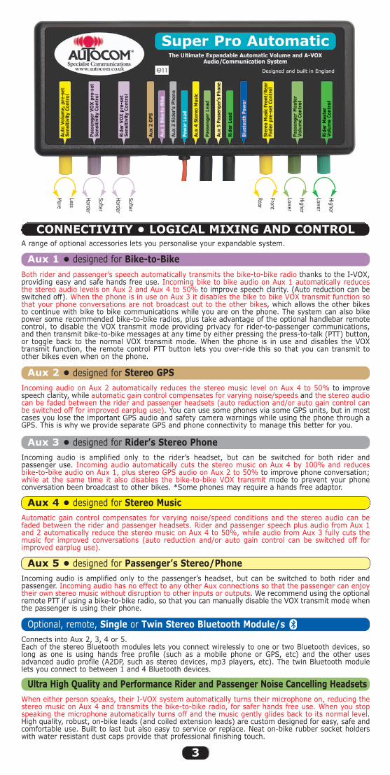
Aux 3 • designed for Rider’s Stereo Phone
Aux 4 • designed for Stereo Music
Incoming audio is amplified only to the rider’s headset, but can be switched for both rider andpassenger use. Incoming audio automatically cuts the stereo music on Aux 4 by 100% and reducesbike-to-bike audio on Aux 1, plus stereo GPS audio on Aux 2 to 50% to improve phone conversation;while at the same time it also disables the bike-to-bike VOX transmit mode to prevent your phoneconversation been broadcast to other bikes. *Some phones may require a hands free adaptor.
Optional, remote, Single or Twin Stereo Bluetooth Module/sConnects into Aux 2, 3, 4 or 5. Each of the stereo Bluetooth modules lets you connect wirelessly to one or two Bluetooth devices, solong as one is using hands free profile (such as a mobile phone or GPS, etc) and the other usesadvanced audio profile (A2DP, such as stereo devices, mp3 players, etc). The twin Bluetooth modulelets you connect to between 1 and 4 Bluetooth devices.
Ultra High Quality and Performance Rider and Passenger Noise Cancelling HeadsetsWhen either person speaks, their I-VOX system automatically turns their microphone on, reducing thestereo music on Aux 4 and transmits the bike-to-bike radio, for safer hands free use. When you stopspeaking the microphone automatically turns off and the music gently glides back to its normal level.High quality, robust, on-bike leads (and coiled extension leads) are custom designed for easy, safe andcomfortable use. Built to last but also easy to service or replace. Neat on-bike rubber socket holderswith water resistant dust caps provide that professional finishing touch.
Automatic gain control compensates for varying noise/speed conditions and the stereo audio can befaded between the rider and passenger headsets. Rider and passenger speech plus audio from Aux 1and 2 automatically reduce the stereo music on Aux 4 to 50%, while audio from Aux 3 fully cuts themusic for improved conversations (auto reduction and/or auto gain control can be switched off forimproved earplug use).
Aux 5 • designed for Passenger’s Stereo/PhoneIncoming audio is amplified only to the passenger’s headset, but can be switched to both rider andpassenger. Incoming audio has no effect to any other Aux connections so that the passenger can enjoytheir own stereo music without disruption to other inputs or outputs. We recommend using the optionalremote PTT if using a bike-to-bike radio, so that you can manually disable the VOX transmit mode whenthe passenger is using their phone.
CONNECTIVITY • LOGICAL MIXING AND CONTROL
Aux 1 • designed for Bike-to-BikeBoth rider and passenger’s speech automatically transmits the bike-to-bike radio thanks to the I-VOX,providing easy and safe hands free use. Incoming bike to bike audio on Aux 1 automatically reducesthe stereo audio levels on Aux 2 and Aux 4 to 50% to improve speech clarity. (Auto reduction can beswitched off). When the phone is in use on Aux 3 it disables the bike to bike VOX transmit function sothat your phone conversations are not broadcast out to the other bikes, which allows the other bikesto continue with bike to bike communications while you are on the phone. The system can also bikepower some recommended bike-to-bike radios, plus take advantage of the optional handlebar remotecontrol, to disable the VOX transmit mode providing privacy for rider-to-passenger communications,and then transmit bike-to-bike messages at any time by either pressing the press-to-talk (PTT) button,or toggle back to the normal VOX transmit mode. When the phone is in use and disables the VOXtransmit function, the remote control PTT button lets you over-ride this so that you can transmit toother bikes even when on the phone.
Aux 2 • designed for Stereo GPSIncoming audio on Aux 2 automatically reduces the stereo music level on Aux 4 to 50% to improvespeech clarity, while automatic gain control compensates for varying noise/speeds and the stereo audiocan be faded between the rider and passenger headsets (auto reduction and/or auto gain control canbe switched off for improved earplug use). You can use some phones via some GPS units, but in mostcases you lose the important GPS audio and safety camera warnings while using the phone through aGPS. This is why we provide separate GPS and phone connectivity to manage this better for you.
Harder
Softer
More
Less
Rear
Front
Harder
Softer
Lower
Higher
Lower
Higher
A range of optional accessories lets you personalise your expandable system.
Super Pro Auto Instructions 8/5/09 2:24 pm Page 3
Having read this manual completely and checked any questions with your dealer, you shouldnow be ready to trial fit and power your main control hub and test to ensure it is completely free fromany electrical interference. Then test and understand how to use the headsets properly before installingthem into your helmets. Then use your helmet/s (leaving your hands free) to listen for any electricalnoise during installing and testing of any audio interfaces/devices, then do the final set up and road test.
Before fully installing the SP-A main control hub unit on your bike (or in a tank bag etc),carefully think it through. There are many ways in which you can install your system but there is usuallyonly one way which is best for you and/or your bike. It is easy to get carried away and do a completeinstallation only to then find problems at the end and not know the cause or how to resolve them. Ifyou follow these instructions carefully you should avoid (or find and cure) any problems during theinstallation, meaning you only need to do it once.
Please note; the SP-A main control hub unit is splash resistant; it is designed not to be completelysealed so as to allow it to breathe. It is however internally protected from damp and the odd splash, soplease consider its location carefully in order to help prevent excessive water contamination. Forexample, do not position it where water will be forced in under pressure, such as in the front of the bikesfaring, or under a wheel arch etc. Look for locations, say under the seat or in a tank bag or whereveryou are sure it will not get soaking wet. Of course reasonable care should also be taken when washingthe bike, especially if you use a jet wash. You may cover the control box with a bag etc when washing,but remove the bag afterwards to ensure the unit can breathe or you may cause damage if it is allowedto build up excessive condensation. If you do not feel you can position the main control unit where it willnot get excessively wet, please ask your dealer about the optional water protector cover.
GETTING STARTED
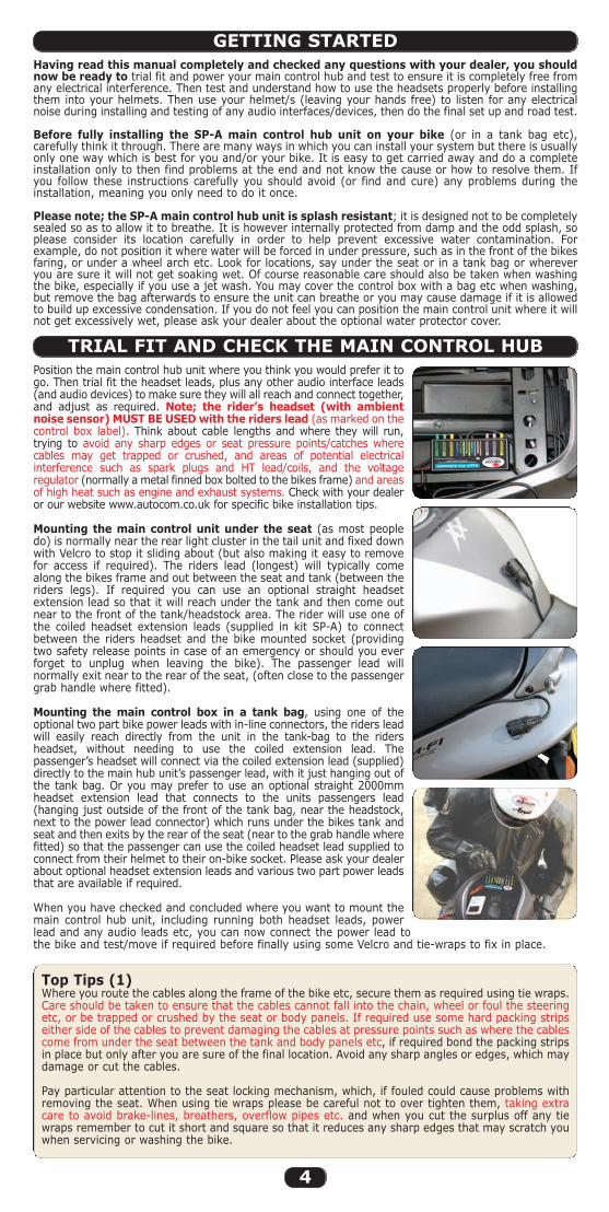
Position the main control hub unit where you think you would prefer it togo. Then trial fit the headset leads, plus any other audio interface leads(and audio devices) to make sure they will all reach and connect together,and adjust as required. Note; the rider’s headset (with ambientnoise sensor) MUST BE USED with the riders lead (as marked on thecontrol box label). Think about cable lengths and where they will run,trying to avoid any sharp edges or seat pressure points/catches wherecables may get trapped or crushed, and areas of potential electricalinterference such as spark plugs and HT lead/coils, and the voltageregulator (normally a metal finned box bolted to the bikes frame) and areasof high heat such as engine and exhaust systems. Check with your dealeror our website www.autocom.co.uk for specific bike installation tips.
Mounting the main control unit under the seat (as most peopledo) is normally near the rear light cluster in the tail unit and fixed downwith Velcro to stop it sliding about (but also making it easy to removefor access if required). The riders lead (longest) will typically comealong the bikes frame and out between the seat and tank (between theriders legs). If required you can use an optional straight headsetextension lead so that it will reach under the tank and then come outnear to the front of the tank/headstock area. The rider will use one ofthe coiled headset extension leads (supplied in kit SP-A) to connectbetween the riders headset and the bike mounted socket (providingtwo safety release points in case of an emergency or should you everforget to unplug when leaving the bike). The passenger lead willnormally exit near to the rear of the seat, (often close to the passengergrab handle where fitted).
Mounting the main control box in a tank bag, using one of theoptional two part bike power leads with in-line connectors, the riders leadwill easily reach directly from the unit in the tank-bag to the ridersheadset, without needing to use the coiled extension lead. Thepassenger’s headset will connect via the coiled extension lead (supplied)directly to the main hub unit’s passenger lead, with it just hanging out ofthe tank bag. Or you may prefer to use an optional straight 2000mmheadset extension lead that connects to the units passengers lead(hanging just outside of the front of the tank bag, near the headstock,next to the power lead connector) which runs under the bikes tank andseat and then exits by the rear of the seat (near to the grab handle wherefitted) so that the passenger can use the coiled headset lead supplied toconnect from their helmet to their on-bike socket. Please ask your dealerabout optional headset extension leads and various two part power leadsthat are available if required.
When you have checked and concluded where you want to mount themain control hub unit, including running both headset leads, powerlead and any audio leads etc, you can now connect the power lead tothe bike and test/move if required before finally using some Velcro and tie-wraps to fix in place.
Top Tips (1)Where you route the cables along the frame of the bike etc, secure them as required using tie wraps. Care should be taken to ensure that the cables cannot fall into the chain, wheel or foul the steeringetc, or be trapped or crushed by the seat or body panels. If required use some hard packing stripseither side of the cables to prevent damaging the cables at pressure points such as where the cablescome from under the seat between the tank and body panels etc, if required bond the packing stripsin place but only after you are sure of the final location. Avoid any sharp angles or edges, which maydamage or cut the cables.
Pay particular attention to the seat locking mechanism, which, if fouled could cause problems withremoving the seat. When using tie wraps please be careful not to over tighten them, taking extracare to avoid brake-lines, breathers, overflow pipes etc. and when you cut the surplus off any tiewraps remember to cut it short and square so that it reduces any sharp edges that may scratch youwhen servicing or washing the bike.
TRIAL FIT AND CHECK THE MAIN CONTROL HUB
4
Super Pro Auto Instructions 8/5/09 2:24 pm Page 4
5
Always connect the BLACK (negative) wire directly to the battery negative terminal using the crimpedeyelet supplied, as this is the best earth on the bike. Not using the battery earth/NEGATIVE is themost likely cause for electrical interference issues. Connect the RED (Positive) wire to a recommended, switched ignition fused supply (5 ampsmaximum, unless you fit an additional in-line fuse of between 3 and 5 amps). Ask your bike supplier ifthey know of any recommended accessory power points on the bike, or consult your bikes handbook,but only use this for the positive supply.
Typical places to find an ignition switched fused supply are the positive feed to the tail lights,or rear brake light switch. Ask your bike dealer if you are not completely sure. Please note that youcan split the red and black power cable as required and cut them to length but don’t do this until youmake the final installation/connection, remember that you may need to move the system to a betterlocation to avoid electrical noise after testing, or perhaps someday onto another bike, so leave plenty ofspare power lead neatly coiled up and secured with a tie-wrap so that it can never fall onto the exhaustor back wheel/chain etc. Do not connect to the brake light circuit if your bike has ABS braking and/or abrake light failure warning system (consult your bike supplier/ manufacturer for approval beforeconnecting to any ABS brake light circuit or bikes that have CANbus). If connection to the brake lightsupply circuit or rear tail light is not recommended, please use some other recommended fused/ignitionswitched 12 volt supply. Always solder the positive joint wherever possible as this provides a moreprofessional and reliable connection. Do not use quick connectors like scotch-locks etc. These are nearlyalways unreliable and most bike manufacturers condemn their use, which may also affect the bikeswarranty. You will notice the supplied fitting kit includes items which will assist in installation e.g. tiewraps, insulation amalgamating tape to cover the soldered positive joint, (again don’t use this for thepre-install test) a crimp type eyelet for connection to battery negative terminal, Velcro to fix the controlbox and if required also speakers into helmet. For added safety and protection the system has reversepolarity protection, which means that it reduces the risk of damage if you accidentally wire the powerlead the wrong way around, however, the unit will not function unless wired correctly. The system alsohas short circuit and thermal overload protection, which means the unit will automatically shut down inthe event of being overloaded e.g. incorrect transceiver used or improper connections. Ask your dealer about optional Part 2437 which can help solve problems if you suffer from electrical noise.
WARNING; extreme caution must be used when working with bike batteries, due to the very highcurrent capacity of the battery, which if shorted; between the battery terminals, or between the batterypositive terminal and ground (the bike frame eetc.) there is a very high risk burns, fire or explosion.
Identify the rider’s headset speaker harness, which has TWO RED mini connectors. Connect therider’s headset via one of the coiled headset extension leads supplied to the riders lead on themain control hub, also connect the passengers headset via the other coiled extension lead to thepassengers lead on the main control hub. DO NOT connect either of the boom microphones, orthe rider’s ambient noise sensor (ANS) just yet, or any other audio interface leads to themain control hub.
Set the rider and passenger master volume controls FULLY anti-clockwise (to their lowestlevels). Set all the other controls on the front panel to their central positions (so that the pointers onthe end of the knobs point to their corresponding pointers on the label).
Start the bike in a well ventilated area, after checking that no parts will fall off onto a hot exhaust etc.Hold the rider’s headset speakers firmly and directly over both ear holes (noting the centre of eachspeaker is slightly offset in the plastic housings) and listen carefully for any electrical interferencethrough the speakers. HT (sparkplug/leads and coils etc) may induce a rapid tick, tick, tick noise whichchanges with engine RPM. Alternator noise if heard is normally a higher frequency constant whine,which again changes with engine RPM, so try to vary the engine RPM while listening carefully throughthe speakers for any induced electrical noise. It should be completely clean and in which case you cannow turn the rider’s volume control fully clockwise (FULL VOLUME) and do the same test again, it shouldbe completely clean. Now do the same tests using the passenger headset to again prove it is completeclear of any electrical interference. It is very unlikely that you will hear any electrical interference whiledoing these tests, but if you do you should carefully move the lead/s about, one at a time, and/or themain control hub unit, while still listening to the speakers with the engine running at varying RPM toidentify which part is picking up the noise and then move it to a clean noise free location.
When you have done this and are happy with the location of the main control hub unit, headset leadsand power leads, you can switch the engine off and Velcro the main control hub unit into place, tie-wrap the headset leads and power lead neatly in place, double checking to avoid any problemsareas as mentioned in Top Tips (1).
When fitting the socket holders to the bike, ensure all surfaces are flat, clean, dry and free from greaseand wax. Note: sockets are designed to tear off if pulled for safety purposes.
We strongly recommend that you test your headsets out of the helmet (before installation)to make it easier for you to experience how even small movements in microphone and speakerpositioning can considerably reduce or improve the sound quality and ease of use. With this knowledgeyou will have a benchmark to work to during final helmet installation later and be sure you are gettingthe very best out of your system. Do not use earplugs during this test as they will hide and/or disguisemuch of what we are trying to listen for.
Avoid pressure directly to the front or back covers of the microphones as this could causedamage. The microphone is floating in an acoustically dampening material to help prevent any helmetvibration being transmitted through the boom to the microphone as part of the noise cancellingmeasures. To move or adjust the microphone please hold it by the outer edges or rubber neck, makingsure that the beige side of the fabric sits flat against and central to your lips. Try to avoid themicrophone covers touching the Velcro on the back of the speakers.
Turn both the rider and passenger master volume controls fully anti-clockwise (to their lowest volumesettings). Connect one of the boom microphones to the riders headset loom, noting the red connectorwill only connect together if aligned the right way round, making sure that it clicks right in, and do thesame for the riders ambient noise sensor (ANS).
CONNECTING THE POWER LEAD TO THE BIKE
TEST THE PRE-INSTALLATION FOR ANY ELECTRICALNOISE, AND MOVE PARTS IF REQUIRED BEFORE FIXING
UNDERSTANDING THE HEADSETS BEFORE HELMET INSTALLATION
Super Pro Auto Instructions 8/5/09 2:24 pm Page 5
6
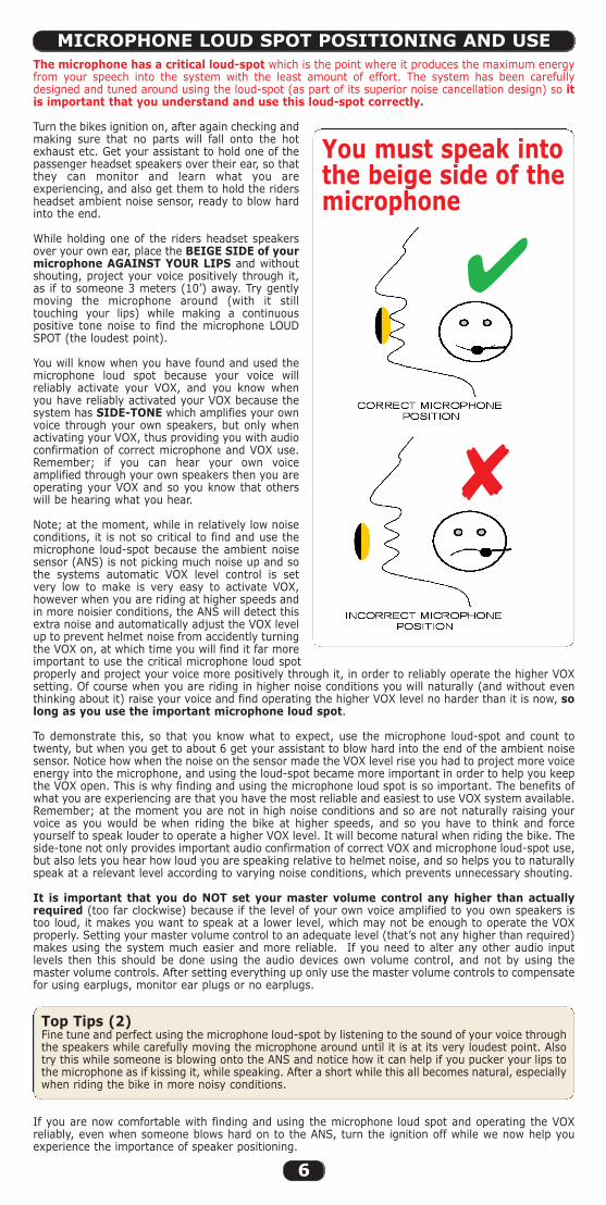
The microphone has a critical loud-spot which is the point where it produces the maximum energyfrom your speech into the system with the least amount of effort. The system has been carefullydesigned and tuned around using the loud-spot (as part of its superior noise cancellation design) so itis important that you understand and use this loud-spot correctly.
Turn the bikes ignition on, after again checking andmaking sure that no parts will fall onto the hotexhaust etc. Get your assistant to hold one of thepassenger headset speakers over their ear, so thatthey can monitor and learn what you areexperiencing, and also get them to hold the ridersheadset ambient noise sensor, ready to blow hardinto the end.
While holding one of the riders headset speakersover your own ear, place the BEIGE SIDE of yourmicrophone AGAINST YOUR LIPS and withoutshouting, project your voice positively through it,as if to someone 3 meters (10’) away. Try gentlymoving the microphone around (with it stilltouching your lips) while making a continuouspositive tone noise to find the microphone LOUDSPOT (the loudest point).
You will know when you have found and used themicrophone loud spot because your voice willreliably activate your VOX, and you know whenyou have reliably activated your VOX because thesystem has SIDE-TONE which amplifies your ownvoice through your own speakers, but only whenactivating your VOX, thus providing you with audioconfirmation of correct microphone and VOX use.Remember; if you can hear your own voiceamplified through your own speakers then you areoperating your VOX and so you know that otherswill be hearing what you hear.
Note; at the moment, while in relatively low noiseconditions, it is not so critical to find and use themicrophone loud-spot because the ambient noisesensor (ANS) is not picking much noise up and sothe systems automatic VOX level control is setvery low to make is very easy to activate VOX,however when you are riding at higher speeds andin more noisier conditions, the ANS will detect thisextra noise and automatically adjust the VOX levelup to prevent helmet noise from accidently turningthe VOX on, at which time you will find it far moreimportant to use the critical microphone loud spotproperly and project your voice more positively through it, in order to reliably operate the higher VOXsetting. Of course when you are riding in higher noise conditions you will naturally (and without eventhinking about it) raise your voice and find operating the higher VOX level no harder than it is now, solong as you use the important microphone loud spot.
To demonstrate this, so that you know what to expect, use the microphone loud-spot and count totwenty, but when you get to about 6 get your assistant to blow hard into the end of the ambient noisesensor. Notice how when the noise on the sensor made the VOX level rise you had to project more voiceenergy into the microphone, and using the loud-spot became more important in order to help you keepthe VOX open. This is why finding and using the microphone loud spot is so important. The benefits ofwhat you are experiencing are that you have the most reliable and easiest to use VOX system available.Remember; at the moment you are not in high noise conditions and so are not naturally raising yourvoice as you would be when riding the bike at higher speeds, and so you have to think and forceyourself to speak louder to operate a higher VOX level. It will become natural when riding the bike. Theside-tone not only provides important audio confirmation of correct VOX and microphone loud-spot use,but also lets you hear how loud you are speaking relative to helmet noise, and so helps you to naturallyspeak at a relevant level according to varying noise conditions, which prevents unnecessary shouting.
It is important that you do NOT set your master volume control any higher than actuallyrequired (too far clockwise) because if the level of your own voice amplified to you own speakers istoo loud, it makes you want to speak at a lower level, which may not be enough to operate the VOXproperly. Setting your master volume control to an adequate level (that’s not any higher than required)makes using the system much easier and more reliable. If you need to alter any other audio inputlevels then this should be done using the audio devices own volume control, and not by using themaster volume controls. After setting everything up only use the master volume controls to compensatefor using earplugs, monitor ear plugs or no earplugs.
Top Tips (2)Fine tune and perfect using the microphone loud-spot by listening to the sound of your voice throughthe speakers while carefully moving the microphone around until it is at its very loudest point. Alsotry this while someone is blowing onto the ANS and notice how it can help if you pucker your lips tothe microphone as if kissing it, while speaking. After a short while this all becomes natural, especiallywhen riding the bike in more noisy conditions.
If you are now comfortable with finding and using the microphone loud spot and operating the VOXreliably, even when someone blows hard on to the ANS, turn the ignition off while we now help youexperience the importance of speaker positioning.
MICROPHONE LOUD SPOT POSITIONING AND USE
You must speak intothe beige side of themicrophone
�
�
Super Pro Auto Instructions 8/5/09 2:24 pm Page 6
7
WARNING; because the system is capable of being VERY LOUD for use with earplugs CAUTIONshould be used when turning the volume control clockwise above the mid-way position unless you areusing conventional earplugs.
Ideally you want to play one of your most favourite pieces of music through the system that has rich soundsand plenty of bass, being something you can identify with later when testing the helmet installation.
Set the rider and passenger master volume controls to their centre positions, so that thepointer on the end of each knob, point to the corresponding pointer on the lid label (this istypically plenty of volume for up to about 120mph without earplugs).
Plug the 3 pole end of the stereo music lead (supplied in the kit) into your music devices headset socketand connect the 4 pole end into Aux 4 socket of your hub.
Top Tips (3)Make sure that you plug your music lead into the music systems headset socket and not the line outsocket, or the volume control may not work.
Turn the ignition on (note youneed to wait about 20 secondsbefore the music will be heard)Adjust the music devices volumecontrol to about half way andthen press play. Listen to checkthat the music is not too loud andadjust as required using themusic devices volume controlbefore holding the speakersdirectly and firmly over yourears.
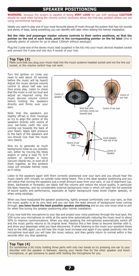
Note that the speakers areslightly off-set in their housingsso try to align the centre of thespeakers directly with centre ofyour ear-holes (with the wirecoming out towards the back ofyour head). Apply light pressureto the back of the speakers andyou should now hear the musicvery clearly.
Now try to generate as muchbackground noise as you possiblycan, either by revving the bikesengine or using a loud TV, hi-fisystem or perhaps a noisyvacuum cleaner etc, or even all ofthem together, as this ambientnoise will simulate helmet noiseas if riding
Listen to the speakers again with them correctly positioned over your ears and you should hear themusic clearly with virtually no outside noise being heard. This is the ideal speaker positioning and youwill notice that moving the speakers just a small amount away from your ears, or out of alignment (up,down, backwards or forwards) can easily half the volume and reduce the sound quality, in particularthe bass response, and let considerable external background noise in which will spoil the full potentialof sound quality and performance, especially at higher background noise levels (higher speeds), orwhen using earplugs.
When you have readjusted the speaker positioning, lightly pressed comfortably over your ears, so thatthe music quality is at its very best and you can hear the least amount of background noise comingthrough, you have found the best possible speaker positioning and so you now know what to aimfor when fine tuning the speaker positioning after helmet installation.
If you now hold the microphone to your lips and project your voice positively through the loud spot, theVOX turns your microphone on while at the same time automatically reducing the music level to about50% to improve communications. When you stop speaking the microphones automatically switch offand the music gently returns to its original level. Practice this a few times to become familiar with it,and show your passenger what you have discovered. If while listening to the music your assistant blowshard on the ANS again, you will hear the music level increase and again if you speak positively into themicrophone loud-spot you will hear the music reduce, and then gently return to normal within a fewseconds after you stop speaking
Top Tips (4)It’s sometimes a bit tricky holding three parts with only two hands so try pressing one ear to yourshoulder with the speaker in between, leaving your hands free for the other speaker and boommicrophone, or get someone to assist with holding the microphone for you.
SPEAKER POSITIONING
Centre ofspeaker
Note that wirenormally comes outtowards back
Centre of ear hole
Centre ofear hole
Centre ofspeaker
Centre of earhole
Avoid speakernear top of ear
Super Pro Auto Instructions 8/5/09 2:24 pm Page 7
8
Because Autocom systems work so much better than other brands, it is easy for people to think itsworking great even when it’s not set up and used properly and only giving you perhaps 30% of whatis really has to offer. This is why we recommend that you to test the headset out of the helmet withsome music, so that after installation you can hear if it sounds right and adjust as required. Using musicis the best way of hearing this, even if you do not intend using music in future. If you install and adjustone helmet first, you can then check the installation against the other headset (out of the helmet) heldproperly in place.
The plug-in boom microphone/s supplied in the kit is our most universal boom designed to fit most fullface, flip front and open face helmets, but please note; most open face and enduro/moto-cross stylehelmets, including flip-front helmets if you want to ride with it open, will require the optional openface conversion kit (Part 2156) to prevent excessive direct wind blast getting to the microphone. Theheadset is not designed to work with 1⁄2 helmets (Chip style) which normally require a much longerboom and perhaps some additional padding to mount the speakers over your ears. Replacementconsumable microphone coverings (Part 2166) and replacement consumable foam speaker covers (Part2155) are available from your dealer. The optional long boom microphone (Part 2075) is similar to ourstandard boom microphone but is 35mm (13⁄8”) longer and is ideal for larger open face helmets.
There are far too many different helmet types available to be able to fully describe every possibleinstallation here, and one must also consider that each year various helmet designs change, so theseinstructions are designed as a basic guide only. Please see your local Autocom dealer or visit our websitewww.autocom.co.uk for more detailed specific helmet installations. Most authorised Autocom dealersare experienced with helmet fitting.
Please note; helmets that have straps that go directly over your ears may not lend themselves for agood headset installation, as the speakers have to sit either on top or behind the straps, which canmake them uncomfortable or out of position which will reduce the sound quality. This is beyond ourcontrol and if our speakers do not fit then nor will any others. It is a good idea to remember this nexttime you choose a helmet. You can overcome this problem by using optional in-ear speaker plugs thatcan replace the standard over the ear type speakers. Consider optional Part 2091 which allowsyou to use most types of monitor (in-ear speaker plugs) with your system.
Some helmets may not lend themselves to be installed as we have suggested and so may requirealternative methods. Please take plenty of time to carefully consider all these basic principles, togetherwith the installation diagrams and your own helmet design to see if you can establish any similaritiesthat may help you with installation. If you are unsure about any of the above then please contact yoursupplier or Autocom for help and advice. DO NOT CUT YOUR HELMET!
Put the helmet on and try to work out exactly where the centre of each ear hole is relative to the strapsor any seams etc in the lining, and also while doing this try to find and mark the exact location of thecentre of your lips inside the chin pad with the helmet sat in its natural position.
When you have established these positions within the helmet you are then ready to start theheadset installation/s.
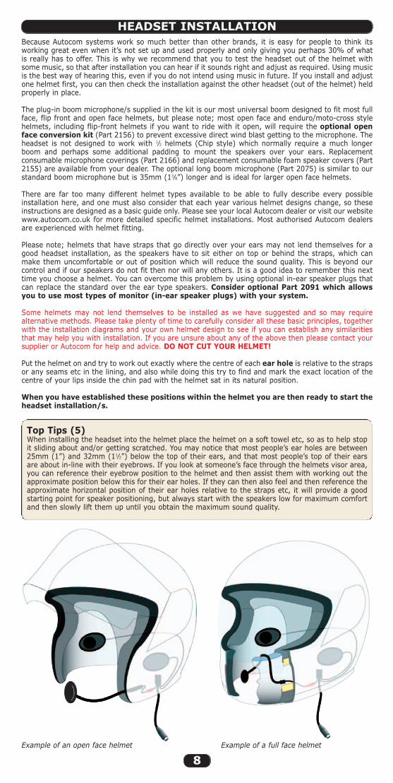
Top Tips (5)When installing the headset into the helmet place the helmet on a soft towel etc, so as to help stopit sliding about and/or getting scratched. You may notice that most people’s ear holes are between25mm (1”) and 32mm (11⁄2”) below the top of their ears, and that most people’s top of their earsare about in-line with their eyebrows. If you look at someone’s face through the helmets visor area,you can reference their eyebrow position to the helmet and then assist them with working out theapproximate position below this for their ear holes. If they can then also feel and then reference theapproximate horizontal position of their ear holes relative to the straps etc, it will provide a goodstarting point for speaker positioning, but always start with the speakers low for maximum comfortand then slowly lift them up until you obtain the maximum sound quality.
HEADSET INSTALLATION
Example of an open face helmet Example of a full face helmet
Super Pro Auto Instructions 8/5/09 2:24 pm Page 8

9
View from undersideof three part type
helmet
View fromunderside
of one part typehelmet
Removestraps and
lift out complete
The fabric is either taped, glued orelasticated over the foam/polystyreneand so it is easy to install the speakersbehind the lining. Note that the wireshould come out of the speaker towardsthe back of the helmet.
Before replacing the cheek pads, tapethe boom and the headset loom to theouter shell or the back side of thecheek pad. When the cheek pad is fittedback into the helmet, it will secure theboom and loom inside the helmet.Do not modify the helmet.
The fabric is either taped, glued orelasticated over the foam/polystyreneand so it is easy to install the speakersbehind the lining. Note that the wireshould come out of the speaker towardsthe back of the helmet.
Before replacing the cheek pads, tapethe boom and the headset loom to theouter shell or the back side of the cheekpad. When the cheek pad is fitted backinto the helmet, it will secure the boomand loom inside the helmet.Do not modify the helmet.
BASIC PRINCIPLE HOW HELMETS ARE ASSEMBLED
Three Part Inner Helmet Design
There are two main types of typical full face helmet designs, one is a one part chin and cheekpad design, per the illustration at the bottom of this page, the other and more popular type is a threepart chin/cheek pad design, per the illustration below. Most full face helmets do not have the cheek pads glued in and are just a compression fit, which makesthem much easier to remove (although some are quite tight).
For more details of open face or flip front helmets please see our website www.autocom.co.uk
One Part Inner Helmet Design
Boom microphone assembly
Peel back tape and lining, slidespeaker inside pushing it right
up to the strap hole
Return assembly as removedTape to holdin place
Removestraps and lift outeach cheek pad
individually
Boommicrophoneassembly
Tape boom to outer shell
Super Pro Auto Instructions 8/5/09 2:24 pm Page 9
10
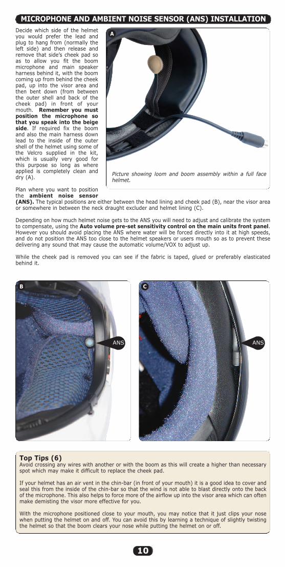
Decide which side of the helmetyou would prefer the lead andplug to hang from (normally theleft side) and then release andremove that side’s cheek pad soas to allow you fit the boommicrophone and main speakerharness behind it, with the boomcoming up from behind the cheekpad, up into the visor area andthen bent down (from betweenthe outer shell and back of thecheek pad) in front of yourmouth. Remember you mustposition the microphone sothat you speak into the beigeside. If required fix the boomand also the main harness downlead to the inside of the outershell of the helmet using some ofthe Velcro supplied in the kit,which is usually very good forthis purpose so long as whereapplied is completely clean anddry (A).
Plan where you want to positionthe ambient noise sensor(ANS). The typical positions are either between the head lining and cheek pad (B), near the visor areaor somewhere in between the neck draught excluder and helmet lining (C).
Depending on how much helmet noise gets to the ANS you will need to adjust and calibrate the systemto compensate, using the Auto volume pre-set sensitivity control on the main units front panel.However you should avoid placing the ANS where water will be forced directly into it at high speeds,and do not position the ANS too close to the helmet speakers or users mouth so as to prevent thesedelivering any sound that may cause the automatic volume/VOX to adjust up.
While the cheek pad is removed you can see if the fabric is taped, glued or preferably elasticatedbehind it.
MICROPHONE AND AMBIENT NOISE SENSOR (ANS) INSTALLATION
Top Tips (6)Avoid crossing any wires with another or with the boom as this will create a higher than necessaryspot which may make it difficult to replace the cheek pad.
If your helmet has an air vent in the chin-bar (in front of your mouth) it is a good idea to cover andseal this from the inside of the chin-bar so that the wind is not able to blast directly onto the backof the microphone. This also helps to force more of the airflow up into the visor area which can oftenmake demisting the visor more effective for you.
With the microphone positioned close to your mouth, you may notice that it just clips your nosewhen putting the helmet on and off. You can avoid this by learning a technique of slightly twistingthe helmet so that the boom clears your nose while putting the helmet on or off.
Picture showing loom and boom assembly within a full facehelmet.
A
B C
ANS ANS
Super Pro Auto Instructions 8/5/09 2:24 pm Page 10

11
Most helmets have ear pockets(indentations) designed into the lining to letyour ears fold back after they are folded overwhile putting the helmet on. Sometimes thefabric covering these ear pockets is gluedback to the polystyrene cheek pad, forming avisible pocket. Other times the fabric is juststretched over the foam pocket and is notglued back.
If the helmet has deep pockets and thefabric is glued back you may need to fitsome padding behind the speakers (like ouroptional foam speaker pads Part 2159 whichare about 6mm or 1⁄4” and/or Part 2160 whichare about 12mm or 1⁄2”). These foam speakerpads have Velcro fitted so that you can fix thespeakers to them. Always start without anypadding and with the speakers setdeliberately low, then test for comfort/soundquality. Then pack out and/or adjust up tothe correct positioning over your ear hole,thus avoiding having the speaker too high ortight where it may cause excessive pressureto the top part of your ears.
If the fabric is not glued back forming avisible pocket then while it is easier to justVelcro the speakers on top of the loose fabric(which can sometimes work quite well insome helmets) it is far more likely to causeyour ears to fold over when putting thehelmet on, so most people prefer a moreprofessional installation where the speakersare set behind the fabric but on top of thefoam/polystyrene behind. If you have timeand can install the speakers behind thefabric, it makes for a much moreprofessional semi permanent fitment, which is normally much more comfortable and this ishow we would normally try to install the headset/s for you if you brought them to us.
In order to be able to place the speakers behind the fabric you normally need to remove the cheek padsfrom the helmet to reveal the back where the fabric is glued, taped or preferably just elasticated overthe polystyrene. Carefully peel the fabric back enough to slide the speakers into place (normally aboutlevel or just below the level of the hole for the strap and just behind the strap). Try to copy theillustrations on pages 8 and 9. Again it is important to start with the speakers set deliberately lower tohelp with maximum comfort and avoid pinching the top part of your ears, and then adjust themupwards as required to obtain the best sound level and quality. If you have to un-glue or un-tape thefabric, masking tape is often used to stick this back down
Please see illustration on page 7 and note that by angling the speakers as shown it helps to ensure evenpressure between the speakers and your ears, thus improving both comfort and sound quality. Thespeaker wire normally exits the speaker towards the back of the helmet.
Only if you have tried everything else first, use your thumb (or something harder, smooth androunded like the back of a screwdriver handle) to carefully compress JUST ENOUGH of the polystyrenefor the wires, boom and loom to slightly recess into the polystyrene to help relieve any pressure. Thiswould NOT normally require more than just 1 or 2 mm (1⁄16”).
Top Tips (7)If your cheek pad has a plastic tongue to hold it in place, be careful not to break this off whenremoving or replacing the cheek pads, and also be careful not to trap or cut the speaker wire/s withit when replacing the cheek pads. When you have installed the headset you can use the back of atoothbrush handle to make a great tool for carefully pushing any wires up into the lining and aroundthe back of the neck draft excluder. You may find it is better to fix the speakers with Velcro so as tohelp avoid them slipping up inside the helmet which can happen over time due to movement whenputting the helmet on. For the first time putting the helmet on after installation it is often beneficialto use something like a silk balaclava to help prevent your ears being folded over while putting thehelmet on and off until you have fine tuned the speaker positioning for maximum comfort andperformance. If for example your right ear is folded over after putting the helmet on you shouldimmediately use your right hand to pull the right hand strap so that you can get your left handfingers up into the right hand side of the helmet to flick your right ear back straight etc. while doingthis you may also be able to feel the speaker position in relation to your ear and if possible try tomove the speaker for a better fit/sound.
Please visit our website: www.autocom.co.uk for further helmet fitting instructions.
SPEAKER INSTALLATION
Super Pro Auto Instructions 8/5/09 2:24 pm Page 11
12
Put the helmet on and play preferably the same piece of music that you listened to earlier, and try tofocus on one speaker/side at a time, while moving the helmet up, down, backwards and forwards andalso side to side to listen for any improvements or loss of sound level and quality.
If for example, moving the helmet forwards (on one side) improves the sound level or quality for thatspeaker, it means your speaker is set too far back, so readjust it forwards until any movement forwardsor backwards only reduces the sound quality/level and does not improve it, meaning that you havefound the best horizontal position for that speaker. Do the same for the other side and then test for upand down.
If for example, moving the helmet up (on one side) improves sound level or quality for that speaker, itmeans the speaker is set too low, so adjust the speaker upwards, and do this accordingly with eachspeaker/side until you are happy that you have the best possible vertical and horizontal positioning foreach speaker.
If you now push the side of the helmet towards your head and notice improved sound, it means youneed to pack that speaker out on some foam so that it is nearer to your ear. Do this to both sides, andthen recheck each side for vertical (up, down) alignment and also again for horizontal (back andforwards) and adjust each speaker until it cannot be improved.
Ensure the sound is equally balance to both ears, if it is slightly louder or has more bass in one ear itmeans the other speaker is out of alignment (or need more packing out) until the sound from bothspeakers are equal
Needless to say you will need to find the best compromise in both comfort and sound quality/level, andyour comfort will almost certainly be your top priority, however please remember that angling thespeakers as show in the diagram on page 7, and avoiding the top part of your ears will greatly help toimprove both positioning/sound level and quality while maintaining maximum comfort.
If you have a helmet that has virtually no tolerance for any speakers (very tight by your ears) youshould NOT CUT the polystyrene, and you will normally find that only a VERY SMALL amount of extraspace, or better speaker positioning would remove all the pressure and make the speakers comfortable.Only if you have tried everything else first, including asking your dealer for advice and/or help first,should you use your thumb (or something harder, smooth and rounded like the back of a screwdriverhandle) to carefully compress JUST ENOUGH of the polystyrene for the speaker magnet to slightlyrecess into the polystyrene to help relieve any pressure. This would NOT normally require more thanjust 1 or 2 mm (1⁄16”) in an area no larger than the magnet on the back of each speaker.
It may take a little extra time now to get each speaker correctly positioned and fine tuned but it willpay huge dividends in sound quality, high speed performance and comfort, especially if you intend usinghigh attenuation earplugs.
When you are convinced that you have fine tuned your speaker positioning to perfection in your firsthelmet installation, you should now retest the other headset (that’s not been installed) and see if youcan hear any difference between the installed headset and the one held properly over your ears? Itreally is worth every minute extra of your time to make the installed headset sound every bit as goodat the one held properly over your ears.
When you have completed your first helmet installation you will almost certainly find that itis a lot easier and less time consuming installing and tuning your second helmet. But if it isdifferent or you have any doubts please ask your supplier for advice.
Top Tips (8)Note you may need to slightly readjust your speakers for more comfort during your first ride out anduntil they have settled in, or perhaps in time should they slide up in your helmet through puttingthe helmet on and off.
If passing an approved Autocom dealer you can ask them if you can compare your headsetinstallation with their ear-defender demo/test headsets in the shop. It is a good idea to do this atleast once every six months just to check your speakers haven’t move over time through putting thehelmet on and off.
TESTING THE INSTALLATION AND FINE TUNING THESPEAKERS AND MICROPHONE POSITIONING
GETTING READY FOR YOUR FIRST TEST RIDE,BEFORE INSTALLING ANY AUDIO LEADS/DEVICES
Double check the main control unit is firmly fixed in place and that both rider and passenger leads, andpower lead are secure. Ensure there are no pressure points trapping any of the cables where they comefrom under the seat or any body panels etc.
Setting the Auto Volume pre-set Sensitivity ControlSet the rider and passenger’s master volume controls and the stereo music front/rear fader pre-setcontrol and auto volume pre-set sensitivity control all to their central positions, so that the pointers onthe end of each knob lines up with their corresponding pointers on the lid label. Set the rider andpassengers VOX pre-set sensitivity controls fully anti-clockwise (very high, to ensure the VOX will notfalse trigger while testing and setting the automatic volume control).
Super Pro Auto Instructions 8/5/09 2:24 pm Page 12
13
Ideally you want to play the same music that you listened to earlier and go for a ride on your own(between 0mph and your typical maximum speeds) and assess how the music level reacts at variousspeeds, which depends on how you adjust the auto volume pre-set sensitivity control to compensatefor the ANS position relative to helmet noise.
Connect the 3 pole end of the music lead supplied into your music systems headset socket and plugthe 4 pole end into the hubs Aux 4 socket. Set the music to a comfortable level while stationary andthen go for a ride to see how the auto volume responds to varying speeds. Do not attempt to speakduring this test as we have deliberately set the VOX levels very high to prevent helmet noise fromaccidently tripping the VOX so that it does not mute the music during this test.
If the automatic volume level goes up too high, too soon then you need reduce the sensitivityby adjusting the Auto Volume pre-set sensitivity control clockwise by about 1⁄8th turn at a time, andtry again.
If you end up with the auto volume pre-set sensitivity control set fully clockwise and the music levelstill rises too high, too soon, then you need to reposition the ANS in the riders helmet so that it hasmore protection from the wind/helmet noise (i.e. bury it deeper into the helmet lining) then start againwith the auto volume pre-set sensitivity control set in its central position and go for another ride andadjust as required.
If the automatic volume level does not go up enough, or goes up too late then you need toincrease the sensitivity by adjusting the auto volume pre-set sensitivity control anti-clockwise byabout 1⁄8th turn at a time, and try again.
If you end up with the auto volume pre-set sensitivity control set fully anti-clockwise and the musiclevel still does not go up enough, or goes up too late, then you need to reposition the ANS in the ridershelmet so that it is more exposed to helmet noise, then start again with the auto volume pre-setsensitivity control set in its central position and go for another ride and adjust as required.
When you are happy with the way the auto volume control is working you should note its position forlater reference and can then set each users VOX controls as follows;
Setting the riders VOX pre-set sensitivity controlStart with the riders VOX sensitivity control turned all the way clockwise (soft/easy/sensitive)and go for a ride to see if the helmet noise at speed can false trigger the VOX. If it does, then slightlyturn the VOX control knob anti-clockwise (say about 1⁄8 of a turn at a time) and try it again. Keep doingthis until you have set the VOX such that helmet noise will not accidentally turn it on at speed whenyou are not speaking.
Top Tips (9)If the riders VOX activates while you are not speaking, first check that you have blocked thevents on the inside of the chin-bar of your full face helmet, as this not only prevents wind fromblowing directly onto the back of the microphone, it also forces more airflow up into the visor areaand so helps with demisting your visor. If using an open face helmet, ensue you have fitted theoptional Open Face Conversion Kit (OFCK) properly to the microphone. If so then the riders VOX pre-set sensitivity control is set too low (too far clockwise) so please turn it 1⁄8th turn anticlockwise at atime (to set the VOX threshold higher) and go for another ride. If required keep doing this until theriders VOX reliable stays off when not speaking.
If the riders VOX is hard to operate, first check that you are properly positioning the microphoneand are using the LOUD-SPOT. (If using an open face helmet, ensue you have fitted the Open FaceConversion Kit (OFCK) properly and the right way round to the microphone). If so then please turnthe rider VOX pre-set sensitivity control 1⁄8th turn clockwise (to set the VOX threshold lower) and gofor another ride. If required keep doing this until the riders VOX is easy to speak to, without helmetnoise activating it when not speaking.
Please repeat this process with the passenger VOX pre-set sensitivity control If after setting the rider and passenger VOX sensitivity controls you ever want to make any adjusts tothe Auto Volume pre-set sensitivity control, you will need to rebalance the rider and passengers VOXpre-set sensitivity controls to suit.
Top Tips (10)Remember to use the microphone loud spot. It is a good idea to set the VOX about 20mph (32kmh)faster than you would normally travel so that head winds do not cause it to false trigger. A wind/draftexcluder is sometimes fitted under the chin bar of some helmets and this can help reduce excessivewind noise at higher speeds thus allowing for a lower VOX setting. If your helmet does not have oneyou can either buy them from some shops of make one. See www.autocom.co.uk for tips on how todo this.
A low VOX setting will cause the music to keep muting and/or bike to bike transceiver to keeptransmitting when not speaking at speed, and this would prevent you from being able to receive biketo bike communications. This is why it is very important to correctly set the VOX and why you mustfind and use the microphone LOUD SPOT rather than reduce the VOX level to compensate. Remembernot having the master volume controls set any higher that required helps you to naturally speak louderand so operate a higher VOX setting with less effort.
You may notice that you have to set the VOX sensitivity slightly higher for the passenger. This is normalbecause the passenger receives more helmet noise, plus gets turbulence off the rider’s shoulders andso normally requires a slightly higher VOX setting.
Super Pro Auto Instructions 8/5/09 2:24 pm Page 13
14
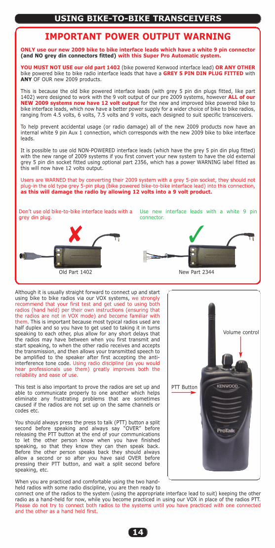
IMPORTANT POWER OUTPUT WARNINGONLY use our new 2009 bike to bike interface leads which have a white 9 pin connector(and NO grey din connectors fitted) with this Super Pro Automatic system.
YOU MUST NOT USE our old part 1402 (bike powered Kenwood interface lead) OR ANY OTHERbike powered bike to bike radio interface leads that have a GREY 5 PIN DIN PLUG FITTED withANY OF OUR new 2009 products.
This is because the old bike powered interface leads (with grey 5 pin din plugs fitted, like part1402) were designed to work with the 9 volt output of our pre 2009 systems, however ALL of ourNEW 2009 systems now have 12 volt output for the new and improved bike powered bike tobike interface leads, which now have a better power supply for a wider choice of bike to bike radios,ranging from 4.5 volts, 6 volts, 7.5 volts and 9 volts, each designed to suit specific transceivers.
To help prevent accidental usage (or radio damage) all of the new 2009 products now have aninternal white 9 pin Aux 1 connection, which corresponds with the new 2009 bike to bike interfaceleads.
It is possible to use old NON-POWERED interface leads (which have the grey 5 pin din plug fitted)with the new range of 2009 systems if you first convert your new system to have the old externalgrey 5 pin din socket fitted using optional part 2356, which has a power WARNING label fitted asthis will now have 12 volts output.
Users are WARNED that by converting their 2009 system with a grey 5-pin socket, they should notplug-in the old type grey 5-pin plug (bike powered bike-to-bike interface lead) into this connection,as this will damage the radio by allowing 12 volts into a 9 volt product.
USING BIKE-TO-BIKE TRANSCEIVERS
Although it is usually straight forward to connect up and startusing bike to bike radios via our VOX systems, we stronglyrecommend that your first test and get used to using bothradios (hand held) per their own instructions (ensuring thatthe radios are not in VOX mode) and become familiar withthem. This is important because most typical radios used arehalf duplex and so you have to get used to taking it in turnsspeaking to each other, plus allow for any short delays thatthe radios may have between when you first transmit andstart speaking, to when the other radio receives and acceptsthe transmission, and then allows your transmitted speech tobe amplified to the speaker after first accepting the anti-interference tone code. Using radio discipline (as you wouldhear professionals use them) greatly improves both thereliability and ease of use.
This test is also important to prove the radios are set up andable to communicate properly to one another which helpseliminate any frustrating problems that are sometimescaused if the radios are not set up on the same channels orcodes etc.
You should always press the press to talk (PTT) button a splitsecond before speaking and always say “OVER” beforereleasing the PTT button at the end of your communicationsto let the other person know when you have finishedspeaking, so that they know they can then speak back.Before the other person speaks back they should alwaysallow a second or so after you have said OVER beforepressing their PTT button, and wait a split second beforespeaking, etc.
When you are practiced and comfortable using the two hand-held radios with some radio discipline, you are then ready toconnect one of the radios to the system (using the appropriate interface lead to suit) keeping the otherradio as a hand-held for now, while you become practiced in using our VOX in place of the radios PTT.Please do not try to connect both radios to the systems until you have practiced with one connectedand the other as a hand held first.
Don’t use old bike-to-bike interface leads with agrey din plug.
PTT Button
Volume control
Old Part 1402 New Part 2344
� �
Use new interface leads with a white 9 pinconnector.
Super Pro Auto Instructions 8/5/09 2:24 pm Page 14
15
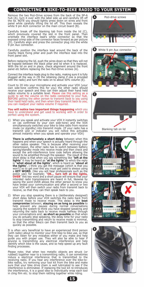
Remove the two Pozi-Drive screws from the back of the SP-Ahub (A), turn it over with the label side up and carefully lift offthe lid. NOTE you should lightly press down on wires and frontpanel while carefully lifting the lid off. This then reveals thewhite 9 pin AUX connector on the main circuit board (B).
Carefully break off the blanking tab from inside the lid (C),which previously covered the slot in the front panel. Thenorientate the interface lead’s white connector so that theexposed crimp side of the connector faces forward as per picture(D). Carefully align and press the connector plug into the white9 pin Aux connector.
Carefully position the interface lead around the back of thenearby black fixing pillar and push the interface lead into thefront panel slot.
Before replacing the lid, push the wires down so that they will notbe trapped between the black pillar and lid when it is replaced.With the lid on and in place, check alignment around the frontpanel etc before replacing the two Pozi-Drive screws (A).
Connect the interface leads plug to the radio, making sure it is fullyplugged all the way in (fit the retaining clamp if one is providedwith the radio) and turn the radio on to about 50% volume (E).
Count to 20 into your microphone and activate your VOX (yourown side-tone confirms this for you) the other radio shouldreceive your speech and they can then adjust their hand heldradios volume to a suitable level. Please use this setting as aguide to set the volume on the radio connected to your hub,BEFORE getting the other person to transmit back to you usingtheir hand held radio, and then when they transmit back to you,you can readjust your radios volume if required.
You will notice two important things happening which youhave to understand and get used to working with in order toperfect using the system.
1) When you speak and activate your VOX it instantly switcheson (as confirmed by your own side-tone) and the VOXsimultaneously switches your bike to bike radio from receivemode (or standby) into transmit mode. (If your radio has atransmit LED or indicator you will notice this activatesalmost instantly when you speak and operate your VOX)
There is unfortunately a short delay between when thishappens and when your speech is actually heard through theother radios speaker. This is because after receiving yourtransmission, the other radio has to switch between batterysaving/standby mode into receive mode and then check andexcept the anti-interference tone code before allowing thesound to be amplified through the speaker. The result of thisshort delay is that when you say something like “left at thelights” it may be heard as “at the lights” to which the replyis “what about at the lights”, which is heard as “about atthe lights”, I think you get the message (which is that youwon’t) so to get over this you must get used to always usinga KEY WORD, (like you will hear professionals such as thepolice use) for example; “OK… turn left at the lights,OVER” this key word and a short pause will ensure that yourintended radio transmissions are heard in full, likewise bysaying the word OVER allows the other person to know youhave ended your communication and after a second or twoyour VOX will then switch your radio from transmit back toreceive, so that they can then speak back to you.
2) When you stop speaking there is a (deliberately designed)short delay before your VOX switches the radio back fromtransmit mode to receive mode. This delay is the bestcompromise between; staying on as long as possible tohelp prevent any pauses during normal conversationscausing the system to think you have stopped speaking andreturning the radio back to receive mode halfway throughyour conversations and; as short as possible so that whenyou do actually stop speaking, the delay time for your radioto stop transmitting and return to receive mode is minimal,so that the other bike/s can then transmit back to you asquickly as possible.
It is often very beneficial to have an experienced third person(with radio) about to monitor your first bike to bike use, so thatthey can listen for any mistakes either of you make and helpguide you with proper use. They will also be able to hear ifanyone is transmitting any electrical interference and helpidentify which bike is the cause, and so help speed up any faultfinding processes.
Please note; that when two metallic objects are struck (orrubbed) together near to a transmitting radio, it can sometimesinduce a electrical interference that is transmitted to thereceiving radio. If you hear any interference over the bike-to-bike radios, try removing your tool kit from the bike and makesure that your bike drive chain is well lubricated to see if theinterference is eliminated. If replacing the tool kit re-introducesthe interference, it is a good idea to individually wrap each toolin cling film etc. to stop them rattling together while riding.
CONNECTING A BIKE-TO-BIKE RADIO TO YOUR SYSTEM
A
B
D
C
E
�
�
Blanking tab on lid
White 9 pin Aux connector
Pozi-drive screws
Super Pro Auto Instructions 8/5/09 2:24 pm Page 15
16
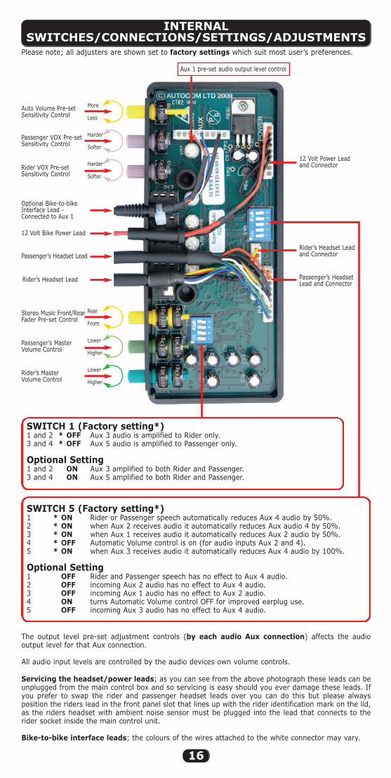
INTERNALSWITCHES/CONNECTIONS/SETTINGS/ADJUSTMENTS
Auto Volume Pre-setSensitivity Control
Passenger VOX Pre-setSensitivity Control
Rider VOX Pre-setSensitivity Control
12 Volt Bike Power Lead
Rider’s Headset Lead
Passenger’s Headset LeadRider’s Headset Leadand Connector
12 Volt Power Leadand Connector
Passenger’s HeadsetLead and Connector
Stereo Music Front/RearFader Pre-set Control
Passenger’s MasterVolume Control
Rider’s MasterVolume Control
Optional Bike-to-bikeInterface Lead -Connected to Aux 1
Aux 1 pre-set audio output level control
Please note; all adjusters are shown set to factory settings which suit most user’s preferences.
The output level pre-set adjustment controls (by each audio Aux connection) affects the audiooutput level for that Aux connection.
All audio input levels are controlled by the audio devices own volume controls.
SWITCH 1 (Factory setting*)1 and 2 * OFF Aux 3 audio is amplified to Rider only.3 and 4 * OFF Aux 5 audio is amplified to Passenger only.
Optional Setting1 and 2 ON Aux 3 amplified to both Rider and Passenger.3 and 4 ON Aux 5 amplified to both Rider and Passenger.
SWITCH 5 (Factory setting*)1 * ON Rider or Passenger speech automatically reduces Aux 4 audio by 50%.2 * ON when Aux 2 receives audio it automatically reduces Aux audio 4 by 50%.3 * ON when Aux 1 receives audio it automatically reduces Aux 2 audio by 50%.4 * OFF Automatic Volume control is on (for audio inputs Aux 2 and 4).5 * ON when Aux 3 receives audio it automatically reduces Aux 4 audio by 100%.
Optional Setting1 OFF Rider and Passenger speech has no effect to Aux 4 audio.2 OFF incoming Aux 2 audio has no effect to Aux 4 audio.3 OFF incoming Aux 1 audio has no effect to Aux 2 audio.4 ON turns Automatic Volume control OFF for improved earplug use.5 OFF incoming Aux 3 audio has no effect to Aux 4 audio.
Servicing the headset/power leads; as you can see from the above photograph these leads can beunplugged from the main control box and so servicing is easy should you ever damage these leads. Ifyou prefer to swap the rider and passenger headset leads over you can do this but please alwaysposition the riders lead in the front panel slot that lines up with the rider identification mark on the lid,as the riders headset with ambient noise sensor must be plugged into the lead that connects to therider socket inside the main control unit.
Bike-to-bike interface leads; the colours of the wires attached to the white connector may vary.
Harder
Softer
More
Less
Rear
Front
Harder
Softer
Lower
Higher
Lower
Higher
Super Pro Auto Instructions 8/5/09 2:24 pm Page 16
17
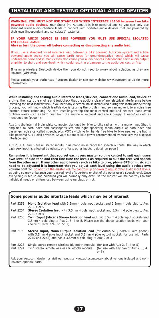
WARNING; YOU MUST NOT USE STANDARD WIRED INTERFACE LEADS between two bikepowered audio devices. Your Super Pro Automatic is bike powered and so you can only usestandard wired audio interface leads to connect with portable audio devices that are powered bytheir own (independent and so isolated) batteries.
IF YOUR AUDIO DEVICE IS BIKE POWERED YOU MUST USE SPECIAL ISOLATEDINTERFACE LEADS.Always turn the power off before connecting or disconnecting any audio lead.
If you use a standard wired interface lead between a bike powered Autocom system and a bikepowered audio device you will cause earth loops (or ground/negative loops) which will causeundesirable noise and in many cases also cause your audio devices independent earth audio outputamplifier to short and over-heat, which could result in a damage to the audio devices, or fire.
If using a wireless Bluetooth device then you do not need to worry about isolation, as they areisolated (wireless).
Please consult your authorised Autocom dealer or see our website www.autocom.co.uk for moreinformation.
INSTALLING AND TESTING OPTIONAL AUDIO DEVICES
While installing and testing audio interface leads/devices, connect one audio lead/device ata time, then start the engine and test/check that the audio is clear of any electrical interference beforeinstalling the next lead/device, If you hear any electrical noise introduced during this installation/testingprocess, you will know which lead/device is causing the problem and so can move it to a noise freelocation before continuing. As with installing/testing the main control hub and headset leads avoidproblem areas such as high heat from the engine or exhaust and spark plugs/HT leads/coils etc asmentioned on (page 4).
Aux 1 is the internal 9 pin white connector designed for bike to bike radios, with a mono input (that isamplified to both rider and passenger’s left and right speakers) mono output of both rider andpassenger noise cancelled speech, plus VOX switching for hands free bike to bike use. As the hub isbike powered Aux 1 also provides 12 volts output to bike power recommended transceivers via a specialinterface lead.
Aux 2, 3, 4, and 5 are all stereo inputs, plus mono noise cancelled speech outputs. The way in whicheach Aux input is affected by others, or affects other inputs is detail on page 3.
Remember it is important that you set each users master volume control to suit each usersown level of side-tone and then fine tune the levels as required to suit the received speechfrom the other user. If any other audio levels (such as bike to bike, phone GPS or music etc)need to be adjusted it is important that you adjust each level using the audio devices ownvolume control. Do not turn the master volume controls up or down to adjust other audio input levels,as doing so may unbalance your desired level of side-tone or that of the other user’s speech level. Onceeverything is set up and balanced you will normally only ever use the master volume control/s to suitindividual needs or differences between using earplugs or not.
Some popular audio interface leads which may be of interest
Part 2253 Mono Isolation lead with 3.5mm 4 pole input socket and 3.5mm 4 pole plug to Aux2, 3, 4 or 5
Part 2254 Stereo Isolation lead with 3.5mm 4 pole input socket and 3.5mm 4 pole plug to Aux2, 3, 4 or 5
Part 2255 Twin Input (Mixed) Stereo Isolation lead with two 3.5mm 4 pole input sockets and3.5mm 4 pole plug to Aux 2, 3, 4 or 5. Please use the above isolation leads with yourchoice of Parts 2240 to 2251)
Part 2190 Stereo Input, Mono Output Isolation lead (for Zumo 500/550/660 with phone)with 3.5mm 4 pole input socket and 3.5mm 4 pole output socket, for use with Parts2245 and 2248) and has a 3.5mm 4 pole plug to Aux 2 or 3
Part 2223 Single stereo remote wireless Bluetooth module (for use with Aux 2, 3, 4 or 5) Part 2224 Twin stereo remote wireless Bluetooth module (for use with any two of Aux 2, 3, 4
or 5)
Ask your Autocom dealer, or visit our website www.autocom.co.uk about various isolated and non-isolated optional parts
Super Pro Auto Instructions 8/5/09 2:24 pm Page 17

18
TROUBLESHOOTING GUIDE
STANDARD 12 MONTHS MANUFACTURERS WARRANTY
Speech volume is too quiet.� Only adjust the riders or passengers volume controls to increase volume levels after you have first
checked you have correctly positioned the speakers and are talking into the beige side of themicrophone and using the microphone loud spot, if required raise your voice.
Phone/GPS/radar/transceiver or music volume is too quiet.� Ensure speakers are correctly positioned (remember speakers may slip up over time).� Adjust volume level on each audio device such as phone/GPS etc to suit.� Only adjust the master volume control/s to increase the overall volume levels.
Music mutes 50% even when I don’t speak.� Increase the VOX level by turning the control anti-clockwise.
Phone will not auto answer.� Ensure your phone has this facility.� Ensure that you have connected the adaptor block properly (if needed).� Check that the phone is set to auto-answer whilst in headset mode (hands free).� Try connecting the adaptor to the phone followed by plugging the lead in.
Problems with bike-to-bike radios� Ensure that you take turns to speak and that you leave 2 seconds between transmissions. See
pages 14 and 15 for hints and tips.� Ensure both transceivers are on the same channel and sub-tone.� Check that the connections on the radio are secure.� Adjust volume level on each transceiver.� Ensure the microphone is positioned correctly and that you are using the loud spot and operating
the VOX see page 6.� If using a press-to-talk (PTT) check the switch position is set to VOX mode.� Ensure tool kits are removed or individually wrap each tool in cling film.
Interference whilst the engine is running.� If you are bike powering your system and any audio devices connected by wire, check that you are
using isolated interface leads. Unplug all accessories and see if the noise is still audible. If the noisehas gone, plug one lead in at a time until the noise returns. You now know which lead is picking upthe noise. It will either need re-routing or it is an incorrect lead.
If you need more help or advice please contact your local Autocom supplier.
If your supplier has not given advice or demonstration on how to set up or use our products, pleasecheck with them before sending any goods back for warranty.
All Autocom products are warranted for a period of 12 months from the date of original purchase, tothe original purchaser, from an authorised Autocom retailer. This warranty covers faulty materials orworkmanship, subject to the goods being used only as stated, and only for the purpose as described inthe instruction manuals.
No manufacturer's warranty applies to the goods where they are used for any other purpose or in anyother way than is explained in the instructions. Nor where the goods have been subjected to misuse,neglect or accidental damage, or used with any other vendor’s products, including incorrect mechanicalor electrical installation, or where the goods have been repaired, modified or altered, without themanufacturer’s written authorisation.
The manufacturer's warranty is limited to the goods being returned pre paid to the manufacturer'sfactory, with the original packaging and the original proof of purchase date. The goods must be intactfor our examination.
This warranty does not cover any consumable items such as batteries, replaceable hygiene foamcoverings for speakers and microphones, or any other items that are described within the instructionmanuals as being a consumable.
Where goods are accepted by the manufacturer, under the terms of the warranty, they will be repairedfree of charge or replaced (at the option of the manufacturer). Where the goods are returned as faultyand are found not to be, a charge will be payable to cover costs of inspection, testing, packing andreturn postage. For details of authorised repair centers available in various countries please ask yourdealer or visit www.autocom.co.uk
The manufacturer's warranty does not affect your statutory rights.
FOR ANY FURTHER HELP OR INFORMATION PLEASE CONTACT YOUR SUPPLIER OR
Autocom Products LimitedUnit 4, Tachbrook Link, Tachbrook Park Drive, Warwick, CV34 6RH. EnglandTelephone: +44 (0)1926 431249 (10 lines) - Fax: +44 (0)1926 431250Email: [email protected] - Website: www.autocom.co.uk
Super Pro Auto Instructions 8/5/09 2:24 pm Page 18

19
PRODUCT REGISTRATION��
�
Dear customer, PLEASE REGISTER YOUR NEW PRODUCTS within 30 daysof purchase and receive priority service, simply by returning thiscompleted form to:
Autocom Products LimitedUnit 4, Tachbrook Link, Tachbrook Park Drive, Warwick, CV34 6RH. England.orfill in a product registration form on-line at; www.autocom.co.uk
CUSTOMER DETAILS
Original purchase date: .................................................................................................
Name: ............................................................................................................................
Address: .........................................................................................................................
......................................................................................................................................
......................................................................................................................................
Post code/Zip code: ............................................Country:.................................................
Telephone: ......................................................................................................................
Email: ............................................................................................................................
Please confirm; I do / do not wish to receive additional or updated information about yourproducts and/or other new products which may be of interest to you.
PrivacyThere is no legal obligation on your part to provide the personal information requested, howeversuch information allows us to maintain a record about the products and how customers aresupplied and supported, which can help improve our standards and speed up any returns/serviceworks. The information collected will be used for marketing purposes by Autocom and ourauthorised distributors only. We may contact you either in relation to the products you alreadyhave or other Autocom products which may be of interest to you.
SUPPLIERS DETAILS (please stamp if available)
Original purchase date: .................................................................................................
Dealers Name: .................................................................................................................
Address: .........................................................................................................................
......................................................................................................................................
......................................................................................................................................
Post code/Zip code: ............................................Country:.................................................
Telephone: ......................................................................................................................
Email: ............................................................................................................................
Member of staff who sold the products (optional).................................................................
Product serial number
Kit SP-A ...........................................................(on side cover)
Super Pro Auto Instructions 8/5/09 2:24 pm Page 19

Unit 4, Tachbrook Link,Tachbrook Park Drive, Warwick CV34 6RH. England
Tel: +44 (0)1926 431249 • Fax: +44 (0)1926 431250Email: [email protected]
Website: www.autocom.co.uk
Super Pro Auto Instructions 8/5/09 2:24 pm Page 20