inverted delta wig effect aircraft 1
TRANSCRIPT

Stability, Control and Performance for an Inverted Delta
Wing-In-Ground Effect Aircraft
Submitted by: Lee Qihui
Department of Mechanical Engineering
In partial fulfillment of the requirements for the Degree of Bachelor of Engineering
National University of Singapore
Session 2005 / 2006

Stability and Control of an Inverted Delta Wing In Ground Effect Aircraft
National University of Singapore I
Summary The objective of this project is to investigate the Wing-In-Ground (WIG) effect on
an Inverted Delta Wing configuration aircraft. It involves the study of
aerodynamics and stability characteristics on a model aircraft, using both
software simulation techniques and actual hardware testing. It encompasses a
multidisciplinary effort to design, build and perform testing on an actual ground
effect model aircraft.
This project can be broadly categories into 3 major milestones, which are all
successfully achieved at the end of the project, and they are:
1) Design and simulations using computational and 3-D engineering software
2) Fabrication and experimental testing for stability and control
3) Actual flight testing under various conditions
The project began with reviews on the work done on WIGs and Inverted Delta
wings. This was then accompanied by the theoretical study on the flight
mechanics of WIG, as well as aerodynamic theory to calculate the forces and
moments acting on the model aircraft and its control surfaces. Stability criteria
were also reviewed and taken into considerations. Equipped with this knowledge,
the aircraft was designed and a control system was planned with the objective of
attaining static and dynamic flight stability, flight manoeuvrability and automatic
height control. This involves developing the transfer functions of the various
control components through self-designed experiments. Simulations were done
to verify the accuracy of the preliminary design, and the various control system
components were tested rigorously again to determine their respective
characteristics. Based on the design made, a model aircraft was then built and a
detailed stability and control analysis was carried out. This was done through a
series of experiments, to test the model for its stability and control effectiveness,
before actual flight tests. Finally, the performance of the aircraft was evaluated
using both land and water testing, conducted over a 2 months period, which
serve to verify its flight capabilities. The aircraft demonstrated great versatility in

Stability and Control of an Inverted Delta Wing In Ground Effect Aircraft
Project Overview its control and maneuvering during the
numerous field tests conducted, justifying the
effectiveness of the control system. In addition,
the automatic height control function was able
to stabilize the plane at the ideal flying height
and provide accurate measurements of flight
altitude and flight time.
National University of Singapore II
Instability Detected
Review and Analysis of
Stability Criteria
Preliminary Design and Simulation using FLUENT and GAMBIT
Construct the WIG Aircraft
Actual Flight Tests to Verify Performance
Good Stability and Control
Instability /Poor Control Detected
Stability Criteria Met
Develop the Transfer Functions to Model the System
Design the Control System and Conduct Experiments to Verify
Effectiveness In the short 9 months, the project team had
successfully attained the initial objectives of
designing, analyzing, fabricating and achieving
a working Inverted Delta WIG aircraft. A simple
project overview is presented in the flowchart
on the right. The stability theory, control
system and test flight results were also
presented at the NUS Centennial Open House
2006.
Design and Conduct Experiments to test
for Stability and Control Effectiveness
In conclusion, the project has successfully
demonstrated the capabilities of an Inverted
Delta WIG aircraft and its immense potential in
the field of high speed marine transport, for
both commercial and military usage. Useful
insights are also gained on the fabrication and
performance of a small scale WIG aircraft.
Fine Tuning and Modifications to achieve a Stable, Working
WIG Aircraft
This project was done in collaboration with a
fantastic friend and teammate, Mr Jiang Junde
who was responsible for the aerodynamics and
propulsion components of this assignment.

Stability and Control of an Inverted Delta Wing In Ground Effect Aircraft
National University of Singapore III
Acknowledgement
The author wishes to express his thanks and heartfelt gratitude to the following
persons for their various contributions and important assistances rendered during
the project.
• A/P Gerard Leng Siew Bing, Project Supervisor, for providing the necessary
guidance and invaluable advice throughout the course of the project.
• Mr Jiang Junde, Project Member and Friend, for his contribution and effort in
the aerodynamic and propulsion analysis.
• Mr Ahmad Bin Kasa, Ms Amy Chee, Ms Priscilla Lee and Mr Cheng Kok
Seng, Staff of the Dynamics & Vibration lab, for their help and support during
the project.
• Mr Kam Mun Loong, Mr Tan Han Yong, Mr Oi Tze Liang and Mr Teoh Wei Lit,
PHD and Masters Students of COSY lab, for their help and encouragement.
• Mr Tan Gee Boon, Nicholas and Mr Ng Kah Yong, Filming Crew and Friends,
for providing relentless assistances in filming the various test flights.
• Ms Lim Weiyee, Web page Designer and Friend, for her help in designing and
developing the website for this WIG project.

Stability and Control of an Inverted Delta Wing In Ground Effect Aircraft
National University of Singapore IV
Table of Contents
1 Introduction .............................................................................................. - 1 -
1.1 Project Objectives.............................................................................. - 2 -
1.2 Structure of the Dissertation .............................................................. - 3 -
2 Literature Review on WIG Aircraft............................................................ - 4 -
2.1 History of WIG Aircraft ....................................................................... - 4 -
2.2 Potential Benefits and Applications of WIG Aircraft ........................... - 6 -
3 Establishing the Stability Criteria of WIG Aircraft ..................................... - 8 -
3.1 Static Stability .................................................................................... - 8 -
3.1.1 Longitudinal Static Stability......................................................... - 8 -
3.1.2 Lateral Static Stability ............................................................... - 11 -
3.2 Dynamic Stability ............................................................................. - 12 -
3.2.1 Longitudinal Dynamic Stability.................................................. - 12 -
4 Stability Analysis .....................................................................................- 13 -
4.1 Initial Analysis.................................................................................. - 13 -
4.2 Designing the Horizontal Tail........................................................... - 14 -
4.3 Determination of CG Position .......................................................... - 21 -
4.3.1 Experiment 1 - Position Estimation........................................... - 22 -
4.3.2 Experiment 2 -Determination of Exact Position ........................ - 22 -
4.4 Thrust Line Alignment...................................................................... - 26 -
5 Aerodynamics Control of WIG Aircraft ....................................................- 28 -
5.1 Design of Control Surfaces and Analysis of Their Effectiveness ..... - 28 -
5.1.1 Elevator .................................................................................... - 28 -
5.1.2 Rudder...................................................................................... - 29 -
5.2 Selection of Control Electronics....................................................... - 30 -
5.3 Determining the Servo Characteristics ............................................ - 32 -
5.4 Integration of Control System .......................................................... - 34 -
6 Designing the Automatic Height Control System ....................................- 35 -
6.1 Hardware Selection and Testing...................................................... - 35 -
6.1.1 Microcontroller and Development Board .................................. - 35 -

Stability and Control of an Inverted Delta Wing In Ground Effect Aircraft
National University of Singapore V
6.1.2 Sensors .................................................................................... - 37 -
6.2 Software Coding .............................................................................. - 39 -
6.3 Establishing the Aerodynamics Transfer Function........................... - 39 -
6.4 Developing the Overall Transfer Function of the System ................ - 42 -
6.5 Implementation of the System ......................................................... - 44 -
7 Flight Tests and Performance Evaluation ...............................................- 45 -
7.1 Ground Testing................................................................................ - 45 -
7.2 Testing on Water Surface ................................................................ - 45 -
7.3 Performance Evaluation Parameters............................................... - 46 -
8 Project Conclusion and Recommendations for Further Study ................- 49 -
8.1 Project Conclusion........................................................................... - 49 -
8.2 Future Directions ............................................................................. - 50 -
List of References...........................................................................................- 51 -
Appendix A: Aerodynamic Coefficients Data and Graphs...............................- 52 -
Appendix B: Servo Specifications ...................................................................- 58 -
Appendix C: Microcontroller and Sensor Specifications..................................- 59 -
Appendix D: TXBasic Code for TattleTale Data Logger..................................- 67 -
Appendix E: Microcontroller Programming Source Codes ..............................- 69 -
E-1: Program for Servo Calibration ......................................................... - 69 -
E-2: Program for Testing Activation Command....................................... - 69 -
E-3: Program for Sensor Readings ......................................................... - 69 -
E-4: Program for Reading, Storing and Displaying Data ......................... - 69 -
E-5: Program for Automatic Height Control Function .............................. - 69 -
Appendix F: Moment of Inertia Calculation .....................................................- 81 -
Appendix G: Root Locus and Bode Plot..........................................................- 82 -
List of Figures Figure 1: Graph showing L/D ratio increasing as h/c decreases...................... - 2 -
Figure 2: KM Ekranoplan – ‘Caspian Sea Monster’ ......................................... - 5 -
Figure 3: Airfisch (Left) and FS8 (Right) .......................................................... - 6 -

Stability and Control of an Inverted Delta Wing In Ground Effect Aircraft
National University of Singapore VI
Figure 4: Forces acting on the WIG aircraft ..................................................... - 8 -
Figure 5: Ideal pitching moment curve and equilibrium condition .................... - 9 -
Figure 6: Relative position of aerodynamic centres for stability ..................... - 10 -
Figure 7: Relative position of aerodynamic centres and CG for stability ........ - 11 -
Figure 8: Moment characteristic curves of Wing alone (orange curve) and
Wing + Hull (green curve) configurations....................................................... - 13 -
Figure 9: Gambit model of the horizontal tail stabilizer unit............................ - 19 -
Figure 10: CFD static pressure contour plot of the entire WIG aircraft model - 20 -
Figure 11: Moment characteristic curves of Wing alone (orange curve),
Wing + Hull (green curve), Tail alone (blue curve) and
Whole aircraft (maroon curve) configurations ................................................ - 20 -
Figure 12: Model aircraft resting on the CG balancing machine .................... - 22 -
Figure 13: Free Body Diagram....................................................................... - 23 -
Figure 14: Illustration of the Experimental Setup ........................................... - 23 -
Figure 15: Free Body Diagram....................................................................... - 24 -
Figure 16: Illustration of the Experimental Setup ........................................... - 24 -
Figure 17: Free Body Diagram....................................................................... - 25 -
Figure 18: Illustration of the Experimental Setup ........................................... - 25 -
Figure 19: Vertical and horizontal alignment of the motors ............................ - 26 -
Figure 20: Experimental setup for the alignment of the motor shafts ............. - 27 -
Figure 21: CFD static pressure contour plot of the horizontal tail stabilizer ... - 29 -
Figure 22: Graph of moment generated against angle of deflection .............. - 31 -
Figure 23: Graph of moment generated by rudder against angle of deflection- 31
-
Figure 24: Schematic of the experimental setup........................................... - 32 -
Figure 25: Servo deflection measurement
Figure 26: Tattletale data logger ................................................................... - 32 -
Figure 27: Graph of output signal of servo against time................................. - 33 -
Figure 28: Control components and their connecting parts............................ - 34 -
Figure 29: Schematic diagram of the control system ..................................... - 35 -
Figure 30: Parallax BASIC Stamp 2SX .......................................................... - 36 -

Stability and Control of an Inverted Delta Wing In Ground Effect Aircraft
National University of Singapore VII
Figure 31: BASIC Stamp Board of Education development board................. - 36 -
Figure 32 : Integrating the microcontroller with the servo to test for signals .. - 37 -
Figure 33: PING ultrasonic sensor SRF08..................................................... - 38 -
Figure 34 : Experimental setup for testing the sensor.................................... - 38 -
Figure 35 : Block diagram representation of automatic height control system- 42 -
Figure 36 : Automatic height control system installed in the WIG aircraft ...... - 44 -
Figure 37 : Static test on the automatic height control system....................... - 44 -
Figure 38 : Ground Effect Mode…………………………………………………..- 45 -
Figure 39 : Ground Effect Mode…………………………………………………..- 46 -
Figure 40 : Graph of height reading against time........................................... - 47 -
Figure 41 : Graph of height reading against time........................................... - 48 -
List of Tables Table 1: Readings from weighing machine for calculating X-Coordinate ....... - 23 -
Table 2: Readings from weighing machine for calculating Y-Coordinate ....... - 24 -
Table 3: Readings from weighing machine for calculating Z-Coordinate ....... - 25 -
Table 4: Servo ratings and specifications ...................................................... - 32 -
Table 5: Servo calibration readings................................................................ - 70 -
Table 6: Moment of inertia calculations.......................................................... - 81 -

Stability and Control of an Inverted Delta Wing In Ground Effect Aircraft
National University of Singapore VIII
LIST OF SYMBOLS c Chord Length
č Mean Chord Length
h Height
h/c Height to Chord Ratio
CL Coefficient of Lift
CD Coefficient of Drag
CM Coefficient of Moment
α Angle of Attack
θ Pitch Angle
δE Angle of Deflection of Elevator
δR Angle of Deflection of Rudder
xcp Center of Pressure
xa/c Aerodynamic center
xθ Aerodynamic center of Pitch
xh Aerodynamic center of Height
XCG X-Coordinate of C.G, with origin at Point A
YCG Y-Coordinate of C.G, with origin at Point A
ZCG Z-Coordinate of C.G, with origin at Point A
b Wing Span
AR Aspect Ratio
Re Reynolds Number
U Reference Velocity / Free Stream Velocity
l Reference Length
ν Kinematics Viscosity
ρ Density
q Pitch Rate
CMα Derivative of the Coefficient of Moment With Respect To Angle of Attack
CM0 Y intercept of the Coefficient of Moment
CLα Derivative of the Coefficient of Lift With Respect To Angle of Attack

Stability and Control of an Inverted Delta Wing In Ground Effect Aircraft
National University of Singapore IX
CMh Derivative of the Coefficient of Moment With Respect To Height
CLh Derivative of the Coefficient of Lift with Respect To Height
CMwf Characteristic Curve of the Coefficient of Moment for Wing-Fuselage
Combination
CMt Characteristic Curve of the Coefficient of Moment for Tail
CMwft Characteristic Curve of the Coefficient of Moment for Wing-Fuselage-Tail
Combination
VH Tail Volume Ratio
CMαt Derivative of the Coefficient of Moment of the Tail With Respect To Angle
of Attack
C M0t Y Intercept of the Characteristic Curve of the Coefficient of Moment of the
Tail
CLαt Derivative of the Coefficient of Lift of the Tail With Respect To Angle of
Attack
ε Downwash Angle
iw Wing Angle of Incidence
it Tail Angle of Incidence
lt Distance between the C.G and a/c of tail
St Area of tail
η Tail efficiency
τ Control Surface effectiveness parameter
Mp Maximum Overshoot
ts Settling Time
tr Rise Time
ξ Damping Ratio
ωn Natural Frequency

Stability and Control of an Inverted Delta Wing In Ground Effect Aircraft
National University of Singapore - 1 -
1 Introduction WIG is an abbreviation for Wing In Ground-effect. A WIG aircraft takes
advantage of this ground effect phenomenon, where an aircraft flying at low
altitudes close to the ground (h/c between 0.05 - 0.25), experiences an increase
in lift on the wings, while drag decreases. This results in an enhanced lift-to-drag
ratio (as shown in Figure 1 below where readings are obtained through CFD
simulations) and hence greater flight efficiency. A WIG aircraft sits on a layer of
dynamic air cushion created by aerodynamics as a result of sufficient forward
speed, rather than static air cushion produced by an engine like in the case of a
hovercraft. This air cushion reduces the friction drag of the WIG craft on water,
which makes it a more efficient vehicle compared to convention marine craft.
WIG aircraft have been around for decades. In the past few years, a large
number of different WIG aircraft have been designed and built. However there
are very limited literatures written on it, especially on an Inverted Delta wing
configuration. Many of the existing results published in journals are based on
experiments done on large scale WIG aircraft, while ground effect phenomenon
on small-scale aircraft is virtually unexplored. Furthermore, little study has been
done to investigate the effect of an Inverted Delta wing configuration, despite its
apparent advantage of enhanced performance and better stability. As such, this
project aims to provide an insight into this unknown and niche area of
aerodynamics, by designing, analyzing, fabricating and experimenting on a small
scale Inverted Delta WIG model. This serves to investigate and demonstrate the
ground effect phenomenon, and how the Inverted Delta wing configuration
contributes to overall stability and enhances performance.

Stability and Control of an Inverted Delta Wing In Ground Effect Aircraft
Lift/Drag Ratio vs. Dimensionless Height (h/c)(For Anhedral Angle = 8, Wing angle of incidence = 3)
8
9
10
11
12
13
14
15
16
17
0 0.05 0.1 0.15 0.2 0.25 0.3Dimensionless Height (h/c)
Lift/
Dra
g R
atio
Wing alone: AA = 8, AoA=3Wing alone: AA = 8, AoA=3
Figure 1: Graph showing L/D ratio increasing as h/c decreases
This project is a joint effort of 2 final year students covering the areas of
aerodynamics, propulsion, stability and control. In this thesis, the stability and
control aspects of the WIG aircraft will be discussed and presented.
1.1 Project Objectives The following objectives are to be achieved:
• Literature review and theoretical study of WIG aircraft’s dynamics, stability
and control.
• Understanding of the Inverted Delta wing configuration
• Stability analysis of the WIG aircraft.
• Stability experiments designed and performed on the WIG aircraft.
• Design, analysis and experimental testing of the individual control
components.
• Integration and experimental testing of the complete control system.
• Test flight of the fabricated prototype.
• Verification of theoretical results against actual flight performance
National University of Singapore - 2 -

Stability and Control of an Inverted Delta Wing In Ground Effect Aircraft
National University of Singapore - 3 -
1.2 Structure of the Dissertation This thesis is divided into 8 Chapters and they are organized as follows:
Chapter 2 – Literature Review on a short history of WIG aircraft and their
potential area of applications.
Chapter 3 – Discusses the theoretical stability criteria for a WIG aircraft. It
includes pitch and height static stability criterions and dynamic stability
considerations.
Chapter 4 – Describes the stability analysis done on the aircraft. It presents CFD
simulation results and describes the designing of a horizontal tail stabilizer. This
section also includes the experiments conducted to find the C.G. of the aircraft
and to align the motors’ thrust lines.
Chapter 5 – Determines the aerodynamic control of the WIG aircraft. It describes
the design of the control surfaces, sizing of the control electronics and the
analysis of their effectiveness. Experiments were performed on individual control
components to determine their characteristics. This is necessary to allow
successful integration of the control system into the WIG aircraft.
Chapter 6 – Discusses the theoretical designing and analysis of an automatic
height control system. This includes hardware selection and testing, software
coding and the determination of aerodynamics transfer function. A block diagram
model representing the entire height control system is derived.
Chapter 7 – Discusses the flight tests conducted under various conditions, and
performance evaluation. The automatic height control system is also examined
Chapter 8 – Project conclusion and recommendations for further study

Stability and Control of an Inverted Delta Wing In Ground Effect Aircraft
National University of Singapore - 4 -
2 Literature Review on WIG Aircraft
The project began with the study of relevant journals, articles and reference texts
documenting the various aspects of WIG aircraft. In addition, thesis done by
previous student on a rectangular wing model WIG aircraft was also examined.
This is to allow for an appreciation of the advantages of a WIG aircraft and its
potential area of applications; and develop an understanding of aerodynamics
theory and the various design considerations for achieving flight stability and
control.
2.1 History of WIG Aircraft
Wing in Ground (WIG) vehicles, or sometimes referred to as Ekranoplans, have
enormous applications in several areas. These areas include cargo
transportation, military operations and even search and rescue missions. The
main reason for the development of WIG aircraft is due to the speed limitations of
conventional marine craft. The practical maximum speed of all marine craft
mentioned so far lies around 100 km/h. The drawback for high speed marine
craft is the increased power requirement and fuel consumption. This is caused by
increased viscous drag due to water friction. The obvious solution is to minimize
contact with the water surface during cruise conditions. This approach works for
hydrofoils and hovercraft. Unfortunately, the speed of a hovercraft is bounded by
the sea state and longitudinal stability considerations; and the speed of a
hydrofoil by cavitations of the foils.
Early experiments of ground effect vehicles were conducted using models and
small scaled prototypes. The best known inventor’s application for a surface
effect vehicle belongs to the Finnish engineer G. Kaario (1935). He built a craft
which was shaped out of a snow plane in the shape of a ski supporting small
elongation wing. Early tests showed positive ground effect. However the project
was halted as he could not solve the instability problem. Similar works were

Stability and Control of an Inverted Delta Wing In Ground Effect Aircraft
carried out by the Swedish and American engineers. However stability problems
plagued their experiments and therefore could not produce any practical
prototypes. Little was known about the control systems for early ground effect
vehicles.
In 1947, a Russian scientist, R.Alekseev made proposals on aerodynamic forces
acting on the motion of high speed craft near the surface. His proposals were
based on the principles of provision of longitudinal and lateral stability near the
surface. It was through these principles that he was able to design and built the
first workable prototype of a WIG aircraft or Ekranoplan. Designs were initially
based upon the tandem wing which was later replaced by the more favorable
“plane” type configuration. This resulted in the production of well-known
Ekranoplans such as the “Lun”, the “Orlyonok” and the most famous of all the
“KM” or “Korabl' Maket”, also known as the Caspian Sea Monster. Weighing at a
staggering 500 tons, this craft is capable of reaching speeds of up to 500km/hr.
Figure 2: KM Ekranoplan – ‘Caspian Sea Monster’
Stability was attained by the inclusion of an enormous horizontal tail. This aids in
counteracting any excessive, unwanted moments. It provides longitudinal trim,
stability and controllability.
National University of Singapore - 5 -

Stability and Control of an Inverted Delta Wing In Ground Effect Aircraft
Incorporated into this enormous aircraft was a system which provided controls for
the elevator, rudder, wing flaps and hinge nozzles. An automatic control system
was used to control the damping and stabilizing of flight altitudes, pitch angle and
speed. With regards to longitudinal stability issues due to ground effect, the WIG
aircraft requires a multi dimensional control system. As such, piloting a ground
effect aircraft is still extremely challenging, with narrow margins for errors.
However, following the collapse of the Soviet Union, developing and maintaining
big ekranoplans became impossible for the Russians and the design bureaus
started focusing on smaller ekranoplans for non-military use. In recent years, the
WIG effect technology has caught the interest of many parties. A few years back,
Boeing Phantom Works announced a project to develop a high-capacity cargo
plane utilizing ground effect for military and commercial purposes. Success was
also seen in the recent development of Airfisch and FS8 WIG aircrafts, designed
by German firm AFD. Even locally in Singapore, there have been interests shown
by engineering companies to design and market commercial WIG aircrafts. This
was the reason why Widgetworks PTE LTD started its collaboration with NUS to
fund projects investigating WIG effect.
Figure 3: Airfisch (Left) and FS8 (Right)
2.2 Potential Benefits and Applications of WIG Aircraft
As a means of transportation, WIG aircraft is well positioned in the niche between
ships and conventional aircraft. Speeds of WIG (up to 500 km/hr) are much
higher than those of high speed ships (typically about 80 km/hr), while
operational expenses are much lower than that of airplanes. In addition, most
National University of Singapore - 6 -

Stability and Control of an Inverted Delta Wing In Ground Effect Aircraft
National University of Singapore - 7 -
WIG aircrafts display amphibious properties and can take off and land on any
relatively flat surfaces, such as land, water, snow and ice. As such, in recent
years, there have been increased interest and research effort put into developing
WIG aircraft for both commercial and military purpose. The following are some
potential benefits and possible applications for WIG aircraft:
• WIG craft can fulfill the need for increased speed of marine transport and
fill the gap between shipping and aviation. It offers itself as a potential
substitute for high speed trans-island transport or international cargo
shipping.
• WIG craft is able to achieve high speeds, while maintaining increase
efficiency and improve lift-to-weight ratio, especially when compared to
other high speed marine craft. This allows WIG aircraft to carry more loads
and cover greater distance, providing enhanced fuel efficiency.
• WIG craft can fly below air defence radars’ zone and are invulnerable to
mine-torpedo weapons. This offers great military application potential for
transporting troops or logistic supplies.
• Due to the marine nature of WIG craft, its operating and maintenance cost
is lower when compared to conventional airplane.
• The infrastructure requirements for WIG craft are very low. Any existing
port facilities are sufficient.
• Especially in a wavy sea, the comfort level in cruise for WIG craft is very
much higher when compared to other high speed marine craft.

Stability and Control of an Inverted Delta Wing In Ground Effect Aircraft
3 Establishing the Stability Criteria of WIG Aircraft
One major aspect of designing a WIG aircraft is to understand, evaluate and
determine its stability criteria. In this section, the various stability criteria will be
discussed, and this forms the basis on which the subsequent stability analysis of the
model WIG aircraft will be based upon.
3.1 Static Stability
Stability is a property of an equilibrium state. That is, if the aircraft is to remain in
steady uniform flight, the resultant force and resultant moment about the C.G must
both be equal 0 as shown in Figure 4. An aircraft satisfying this requirement is said
to be at trim condition. On the other hand, if the forces and moments do not sum to
0, the airplane will be subjected to translational and rotational accelerations,
resulting in instability.
LiftTail
LiftWing
LiftWing
Thrust
Thrust
Drag C.G For stability: ΣF = 0 ΣMCG = 0
Weight
Figure 4: Forces acting on the WIG aircraft
The subject of stability is generally divided into static and dynamic stability. Static
stability refers to the initial tendency of the aircraft to return to its equilibrium or trim
state after a disturbance. If there exists a natural tendency for the aircraft to
generate a restoring force or moment to return to its equilibrium point, then the
aircraft is said to be statically stable.
3.1.1 Longitudinal Static Stability Longitudinal static stability of the WIG aircraft is extremely sensitive to both pitch and
height variations. This is quite different from conventional aircraft where changes in
National University of Singapore - 8 -

Stability and Control of an Inverted Delta Wing In Ground Effect Aircraft
height results in minimal force and moment variations, and as such, is ignored and
only requires consideration for pitch stability.
However, in the presence of ground effect, force and moment acting on the aircraft
change with both pitch and height. Therefore, both pitch and height stability
considerations must be taken. A WIG aircraft has two aerodynamic centers. The
center of pitch xθ follows conventional aerodynamics definition and is where the
moment acting on the body is independent of the angle of attack. Similarly, the
centre of height xh is defined as the point where moment is independent of flying
height. These two aerodynamic centers can be obtained by considering the Lift and
Moment curve with respect to angle of attack and with respect to height.
Pitch Stability Criterion: For pitch stability, the required conditions are well illustrated in the following diagram.
Figure 5: Ideal pitching moment curve and equilibrium condition
At trim condition, the aircraft is at equilibrium and flying at an angle of attack, where
there are no moment tendencies to pitch the aircraft about its C.G. At angle of attack
less than αtrim, the aircraft creates a positive (nose-up) moment that would rotate it
back towards the equilibrium point. On the other hand, if the aircraft experiences a
disturbance, such as a sudden upward gust, that increases the angle of attack to
greater than αtrim, a negative (nose-down) moment will develop and tend to rotate it
back to the equilibrium. On the basis of this simple analysis, to have static pitch
National University of Singapore - 9 -

Stability and Control of an Inverted Delta Wing In Ground Effect Aircraft
stability, the aircraft pitching moment curve must have a negative slope and intercept
the positive Y-axis.
CMα < 0 (1) CM0 > 0 (2) Height Stability Criterion: By Routh – Hurwitz Criteria, the condition of height stability for a WIG aircraft can be
mathematically expressed as:
∆X = Xθ – Xh > 0 (3)
Where (XCG / č – Xθ / č) = CMα / CLα
(XCG / č – Xh / č) = CMh / CLh
Centre of Height Xh
Centre of Pitch Xθ
Figure 6: Relative position of aerodynamic centres for stability
That is to say, the final configuration of the aircraft must be such that the
aerodynamic center of height is located upstream of the aerodynamic center of pitch.
In addition, research results show that the ideal ∆X should be between 0.05 - 0.20č.
If ∆X > 0.20č, then the static stability becomes excessive leading to dynamic
instability. On the other hand, if ∆X < 0.05č, then there is insufficient stability which
can lead to long-period (phugoid) fluctuations.
C.G Positioning: The location of the C.G. is crucial for establishing acceptable longitudinal stability as
it affects the dynamics of the aircraft. Sensitivities of the pitch angle and flight
altitude to changes in velocity are important for determining an ideal C.G position.
The derivative of pitch angle with respect to velocity can be shown to be:
dθ /dU = -2/U [CL / (dCL / dθ)] [Xh / (Xθ – Xh)] (4)
National University of Singapore - 10 -

Stability and Control of an Inverted Delta Wing In Ground Effect Aircraft
Similarly, the derivative of flight altitude with respect to velocity is:
dh /dU = 2/U [CL / (dCL / dh)] [Xθ / (Xθ – Xh)] (5)
Looking at equation (4), if the aerodynamic centre of height coincides with the C.G
position, then Xh, when measured with respect to C.G, is zero and the pitch angle
will not vary with velocity. If C.G is between the aerodynamic centre of height and
centre of pitch, then Xh < 0 and (Xθ – Xh) > 0; and the pitch angle will decrease with
increasing velocity as seen in equation (4). Furthermore, according to equation (5),
when C.G is between the two aerodynamic centres, Xθ > 0 and the term [Xθ / (Xθ –
Xh)] < 1, this will lead to an increase in damping effect and is desirable. On the other
hand, if C.G is in front of both aerodynamic centres, then Xh > 0, Xθ > 0 and [Xθ / (Xθ
– Xh)] > 1, which represent a decrease in damping effect and an increase in height
variation with velocity. Therefore, to achieve stability, C.G should be located
between the two aerodynamic centres, and placed close to the centre of height, as
expressed in equation (6) below.
Xh < XCG < Xθ and XCG ∼ Xh (6)
Centre of Height Xh
Centre of Pitch XθC.G
Figure 7: Relative position of aerodynamic centres and CG for stability
3.1.2 Lateral Static Stability Lateral stability refers to stability in the roll axis. An aircraft possesses static roll
stability if a restoring moment is developed when it is disturbed from a wings-level
attitude. When a WIG aircraft is rolled, the pressure on its lifting surfaces changes
and is redistributed. Part of the lifting elements approaches the ground and hence
experiences an increase in lift; while the other part deviates from it with a resulting
decrease in lift. This situation causes the generation of a recovering moment that
National University of Singapore - 11 -

Stability and Control of an Inverted Delta Wing In Ground Effect Aircraft
National University of Singapore - 12 -
brings the aircraft back to wing level. In addition, by adopting a high wing
configuration, there will be a stabilizing roll moment created by the flow around the
fuselage. Therefore a WIG aircraft, unlike a conventional airplane, has a natural
aerodynamic stabilization of roll angle in flight. This is an extremely important aspect
of flight safety.
3.2 Dynamic Stability
The study of dynamic stability focus on the time response of motion of the aircraft
after it is disturbed from its equilibrium point and is determined by the character of
this disturbed motion. It examines important parameters such as frequency and
period of motion, damping ratio and settling time. If the disturbance reduces with
time, it indicates that there is resistance to the motion and therefore energy is
dissipated. The dissipation of energy is called positive damping. On the other hand,
if energy is being added to the system, then it is known as negative damping.
Positive damping for an aircraft is provided by forces and moments that arise due to
the aircraft’s motion. This positive damping will oppose the motion of the aircraft and
cause the disturbance to damp out over time. How long it will take for the system to
settle down will depend on the damping ratio. An aircraft that has negative
aerodynamic damping will be dynamically unstable. It is important to note that an
aircraft can be statically stable but dynamically unstable. Static stability, therefore,
does not guarantee dynamic stability.
3.2.1 Longitudinal Dynamic Stability To ensure longitudinal dynamic stability, the C.G of the WIG aircraft should be
located within a certain range, as specified in equation (6).In addition, it is important
to understand the equation of pitching motion of the WIG aircraft to determine the
time response, when it is subjected to external disturbances or changes in control
input. If the aircraft is able to stabilise and achieve steady state, rather than go into
an extended state of fluctuation, then it is dynamically stable. The pitching moment
equation and aircraft transfer function will be derived in chapter 6 of this report.

Stability and Control of an Inverted Delta Wing In Ground Effect Aircraft
4 Stability Analysis
Following the theoretical studies of stability criteria, it is vital to ensure that these
conditions are implemented in the model aircraft as accurately as possible.
Before any flight testing can commence, it is important to conduct laboratory
based experiments on the completed aircraft to analyse and verify that necessary
stability conditions are indeed fulfilled. This will help to ensure good flight
performance and minimise instability.
4.1 Initial Analysis
CFD simulations are initially done on Wing alone and Wing + Hull configurations
to obtain a series of force and moment readings. The moment characteristics
curves plotted, for both configurations, are upward sloping and intercept the
negative Y-axis as shown in Figure 8 below. Based on stability theory shown in
equation (1) and (2) earlier, this represents an inherent instability.
Coefficient of Moment (CM) vs. Angle of Attack(For Anhedral Angle = 8, h/c = 0.1 Wing angle of incidence = 3)
y = 0.0082x - 0.0178
y = 0.0118x - 0.0229
-0.5
-0.4
-0.3
-0.2
-0.1
0
0.1
0.2
0.3
0.4
-8 -6 -4 -2 0 2 4 6 8 10
Angle of Attack
Coe
ffici
ent o
f Mom
ent (
CM)
Wing alone: AA = 8, h/c = 0.1
Wing + hull: AA=8, h/c=0.1
Wing alone: AA = 8, h/c =0.1
Wing + hull: AA=8, h/c=0.1
Figure 8: Moment characteristic curves of Wing alone (orange curve) and Wing + Hull (green curve) configurations
National University of Singapore - 13 -

Stability and Control of an Inverted Delta Wing In Ground Effect Aircraft
National University of Singapore - 14 -
In addition, considering the Wing + Hull configuration, the centre of pitch and
centre of height are found to be:
Given that centre of gravity, XCG = 0.28č, where č = 0.535cm
(XCG / č – Xθ / č) = CMα / CLα = 0.0118 / 0.0696 = 0.170
Xθ = (0.280 – 0.170) č = 0.110č = 0.059 m from leading edge
(XCG / č – Xh / č) = CMh / CLh = -0.0654 / -0.6362 = 0.103
Xh = (0.280 – 0.103) č = 0.177č = 0.095 m from the leading edge
This shows that the centre of height is aft of the centre of pitch (∆X = Xθ – Xh <
0), and thus, the height stability criterion as stated in equation (3) is not met. This
results in instability.
Lastly, the ideal C.G position of 0.28č (0.15m) from the leading edge is not
between, but instead, behind the two aerodynamic centres. This contributes to
the instability of the aircraft.
4.2 Designing the Horizontal Tail
To correct this instability problem, a horizontal tail stabilizer needs to be
introduced to create a correcting moment that can balance the aircraft and help
attain trim condition. The horizontal tail will also help to shift the centre of pitch
downstream.
In designing the horizontal tail stabilizer, several parameters have to be
considered. This includes the airfoil data, span and chord dimensions, aspect
ratio, distance of the tail from the C.G position and tail angle of incidence. The
whole design process begins with making an estimation of the ideal pitching
moment characteristic curve required from the whole aircraft. From earlier

Stability and Control of an Inverted Delta Wing In Ground Effect Aircraft
National University of Singapore - 15 -
simulations, it is determined that the ideal trim condition for the aircraft should
occur at an angle of attack of approximately 4°. This is because at this angle, the
wings are able to generate the necessary lift required to carry the design
payload. Furthermore, the positive Y-intercept for the moment curve is set at
0.06. This is to satisfy the stability criteria. As such, the ideal moment equation is:
CMα wft = - 0.015 α + 0.06
Considering the moment characteristic curve for the Wing + Hull configuration
which is found to be:
CMα wf = 0.0118 α - 0.0229
Therefore, the tail must contribute:
CMα t = CMα wft - CMα wf = -0.015 – 0.0118 = - 0.0268 /°
CM0 t = CM0 wft - CM0 wf = 0.06 – (-0.0229) = 0.0829
The pitching moment due to the tail can be approximated by the following
equation:
Mt = - lt Lt = - lt CLt 0.5 ρ Ut2St (7)
CMt = Mt / (0.5 ρ U2 Sč) = - (lt St / Sč) ηCLt = - VH ηCLt (8)
The Coefficient of Lift for the tail can be written as:
CLt = CLαt αt = CLαt (αw - iw – ε + it) (9)
The downwash angle can be expressed as:

Stability and Control of an Inverted Delta Wing In Ground Effect Aircraft
National University of Singapore - 16 -
ε = ε0 + dε/dαw αw (10)
where ε0 is the downwash at zero angle of attack
The downwash behind a wing can be derived from the finite-wing theory and
shown to be related to the wing lift coefficient and aspect ratio:
ε = 2CLw / π ARw (11)
The rate of change of downwash angle with angle of attack is determined by
taking derivative of equation (10):
dε/dαw = (2CLαw / π ARw) (12)
Now, rewriting the tail contribution to the pitching moment by substituting
equation (9) and (10) into equation (8) yields:
CMt = ηVH CLαt (ε0 + iw – it) - ηVH CLαt α(1 - dε/dαw) (13)
Comparing equation (10) with the linear expression for the tail pitching moment
characteristic curve,
CMt = CM0 t + CMα t α
yields expressions for the slope and the Y- intercept:
CM0 t = ηVH CLαt (ε0 + iw – it) (14)
CMα t = - ηVH CLαt (1 - dε/dαw) (15)
Stability and Control of an Inverted Delta Wing In Ground Effect Aircraft
National University of Singapore - 17 -
As seen from equation (14), the tail contribution to CM0 is positive and can be
used to ensure that the overall CM0 of the WIG aircraft intercept the positive Y-
axis, as required for stability. This can be accomplished by adjusting the tail
incidence angle it. In addition, equation (15) shows that the tail should contribute
a negative gradient moment curve to the overall moment characteristic of the
entire WIG aircraft and help to enhance stability. This can be controlled by proper
selection of VH and CLαt. The contribution of CMα t will become more negative by
increasing the tail moment arm lt or tail surface area St and by increasing CLαt.
The tail lift curve slope CLαt can be increased most easily by increasing the
aspect ratio of the tail platform.
To simplify the design process, the following parameters are first estimated and
set:
• Aspect Ratio tail = (b/c)t =ARt = 2.2 • Tail moment arm, lt = 0.465 m
• Tail efficiency, η = 0.5 ρ Ut2 / 0.5 ρ Uw
2 = 1
• CLαt ≈ CLα w = 0.0559 /°
Note that: CLα w and CL0 w are obtained from the Lift vs Angle of Attack (Wing
Alone configuration) curve.
From equation (12): dε/dαw = (2CLαw / π ARw) = 2 ( 0.0559/°) / π (1.98) = 0.0178 From equation (15), solving for the tail volume ratio: VH = - CMα t / [η CLαt (1 - dε/dαw)] Substituting all the relevant values gives: VH = - (-0.0268 /°) / [(1) (0.0559 /°)(1 – 0.0178)] = 0.488 m3 The horizontal tail volume ratio is expressed as VH = (lt St / Sč) and solving for the horizontal tail area yields:
Stability and Control of an Inverted Delta Wing In Ground Effect Aircraft
National University of Singapore - 18 -
St = (0.488) (0.250) (0.535) / 0.465 = 0.140 m2
Setting ARt = 2.2, bt / ct = 2.2 St = ct x 2.2 ct = 0.140 Therefore, ct = 0.252 m and bt = 2.2 x ct = 0.554 m This is the tail configuration needed to provide the required tail contribution to
CMα, so that the ideal moment curve is achieved.
Next is to determine the tail angle of incidence. From equation (14):
it = - ([CM0 t / ηVH CLαt] - iw - ε0 ) (16)
The only unknown in equation (16) is ε0; that is, the downwash angle at the tail
when the wing is at zero angle of attack. This can be estimated using equation
(11):
ε0 = 2CL0 w / π ARw = 2(0.0846) / π (1.98) = 0.027° Now solving for equation (16) gives: it = - ([0.0829 / (1) (0.488) (0.0559)] – 3 – 0.027) = 0.012° ≈ 0° The calculations above provide the basic parameters on which the design,
simulation and construction of the horizontal tail will be based upon.
To verify the performance of the horizontal tail design and justify the theoretical
calculations made above, a series of CFD simulations is done to determine the
lift and moment generated on the tail at various angles of attack. A GAMBIT
model of the tail, that has been carefully meshed, is shown in Figure 9 below.

Stability and Control of an Inverted Delta Wing In Ground Effect Aircraft
Figure 9: Gambit model of the horizontal tail stabilizer unit
The moment characteristic curve of the tail is then plotted (as seen in Figure 11)
to ensure that the simulations readings are in close accordance to the theoretical
results obtained above. From the plotted curve, the moment equation of the tail is
found to be:
CMα t = - 0.0273 α + 0.0846 This is very close to the theoretical equation CMαt = - 0.0268 α + 0.0829
mentioned above.
Finally, the moment characteristic curve of the entire aircraft is plotted (as seen in
Figure 11) using simulation results, to ensure that its gradient is negative and it
intercepts the positive Y-axis, as required to satisfy longitudinal stability
conditions. An example of the CFD static pressure contour plot of the aircraft is
shown in Figure 10 below. From the plotted curve, the moment characteristic
equation of the entire aircraft is found to be:
CMα wft = - 0.0156 α + 0.063 Once again, this curve, obtained from simulation results, is found to be in close
agreement to the theoretical equation CMα wft = - 0.015 α + 0.06 stated before.
Also note that the trim angle is approximately at 4° as specified earlier.
National University of Singapore - 19 -

Stability and Control of an Inverted Delta Wing In Ground Effect Aircraft
Figure 10: CFD static pressure contour plot of the entire WIG aircraft model
Coefficient of Moment (CM) vs. Angle of Attack(For Anhedral Angle = 8, h/c = 0.1 Wing angle of incidence = 3)
y = 0.0082x - 0.0178
y = 0.0118x - 0.0229
y = -0.0273x + 0.0846
y = -0.0156x + 0.063
-0.6
-0.5
-0.4
-0.3
-0.2
-0.1
0
0.1
0.2
0.3
0.4
0.5
-8 -6 -4 -2 0 2 4 6 8 10
Angle of Attack
Coe
ffici
ent o
f Mom
ent (
CM)
Wing alone: AA = 8, h/c = 0.1
Wing + hull: AA=8, h/c=0.1
Tail alone: h/c =0.1
Whole Aircraft
Wing alone: AA = 8, h/c =0.1
Wing + hull: AA=8, h/c=0.1
Tail alone: h/c=0.1
Whole Aircraft
Figure 11: Moment characteristic curves of Wing alone (orange curve), Wing + Hull (green curve), Tail alone (blue curve) and
Whole aircraft (maroon curve) configurations
National University of Singapore - 20 -

Stability and Control of an Inverted Delta Wing In Ground Effect Aircraft
National University of Singapore - 21 -
As seen in Figure 11 above, following the addition of the horizontal tail stabilizer,
the moment characteristic curve for the entire aircraft is now downward sloping
and intercepting the positive Y-axis. The trim condition occurs at approximately
4° angle of attack as desired. This satisfies the pitch stability criteria established
earlier.
In addition, the centre of pitch and centre of height are now found to be:
(XCG / č – Xθ / č) = CMα / CLα = -0.0156 / 0.1274 = -0.122
Xθ = (0.280 + 0.122) č = 0.402č = 0.215 m from leading edge
(XCG / č – Xh / č) = CMh / CLh = -0.0671 / -0.9862 = 0.068
Xh = (0.280 – 0.068) č = 0.212č = 0.113 m from the leading edge
From the above calculations, the aerodynamic center of height is now located
upstream of the aerodynamic center of pitch and ∆X is 0.19č. Furthermore, the
ideal C.G position (0.15m from the leading edge) is now in between the two
aerodynamic centres. As such, stability conditions, as specified in equation (3)
and (6), are now satisfied.
In summary, the level of longitudinal static stability can be controlled through
proper selection of the horizontal tail, by manipulating the volume ratio. The
parameters making up the volume ratio that can be varied is the horizontal tail
surface area and distance between the C.G and a/c of the tail. In addition, the tail
incidence angle can be adjusted to yield whatever CM0 needed to achieve the
desired trim condition.
4.3 Determination of CG Position
As discussed earlier, the placement of the CG position is a major factor in
ensuring stability. Based on above theoretical results, the aerodynamics centre of
pitch and centre of height are found to be at 0.402č and 0.212č respectively. As

Stability and Control of an Inverted Delta Wing In Ground Effect Aircraft
such, the CG position should ideally be between these two points and is fixed at
0.280č. Design and fabrication considerations are taken into an account to
ensure that this position is achieved. After the fabrication has been completed,
two separate experiments are conducted to verify that the C.G position is indeed
at its ideal point as planned earlier.
4.3.1 Experiment 1 - Position Estimation Using a commercial, off-the-shelf C.G balancing machine, the model aircraft is
rested and balanced on the device to estimate an approximate region where the
C.G position lies. The experimental setup is illustrated in Figure 12 below. This is
to mark out the region of interest, in which the later experiment 2 will be focusing
on, to determine the exact C.G location and its 3-dimensional coordinates.
Figure 12: Model aircraft resting on the CG balancing machine
As seen above, the model aircraft with all its various components installed
balances itself at the approximate C.G position when placed on the balancing
machine. This helps to identify a rough region where the CG lies and the exact 3-
dimensional coordinates will be determined in Experiment 2.
4.3.2 Experiment 2 -Determination of Exact Position A series of experiment, based on simple force–moment theory, is designed to
measure and calculate the exact coordinates of the C.G position.
National University of Singapore - 22 -

Stability and Control of an Inverted Delta Wing In Ground Effect Aircraft
Before the experiment, the total weight of the aircraft, w is found to be 2.027kg
Y-coordinate:
The experimental setup for calculating the Y-Coordinate of the CG position is
illustrated in the following diagram and the table shows the readings obtained:
Y
0.135 m
R - Force reading from the weighing machine
Datum pt A
W
Figure 13: Free Body Diagram
Table 1: Readings from weighing machine for calculating X-Coordinate
R1 /kg R2 /kg R3 /kg RAvg /kg RFY/N 1.276 1.280 1.277 1.278 12.54
Figure 14: Illustration of the Experimental Setup
Sample calculation:
Having known RFY = 12.54N, YCG can be determined by taking moment about
point A:
Taking anticlockwise moment as +ve:
ΣMA = w (9.81) (0.135 – YCG) – RFY (0.135) = 0
National University of Singapore - 23 -

Stability and Control of an Inverted Delta Wing In Ground Effect Aircraft
(2.027) (9.81) (0.135 - YCG) – (12.54) (0.135) = 0
YCG = 0.050m (from the right edge of the hull) X-Coordinate: The experimental setup for finding the X-Coordinate of the CG position is
illustrated in the following diagram and the table tabulates the readings obtained:
Datum pt A
X
0.135 m
R - Force reading from the weighing machine
W
Figure 15: Free Body Diagram
Table 2: Readings from weighing machine for
calculating Y-Coordinate
R1 /kg R2 /kg R3 /kg RAvg /kg RFX /N0.048 0.050 0.047 0.049 0.48
Figure 16: Illustration of the Experimental Setup Sample calculation: Knowing that RFX = 0.48N, XCG can be determined by taking moment about point
A:
Taking anticlockwise moment as +ve:
National University of Singapore - 24 -

Stability and Control of an Inverted Delta Wing In Ground Effect Aircraft
ΣMA = - w (9.81) (0.135 – XCG) + RFX (0.135) = 0
- (2.027) (9.81) (0.135 - XCG) + (0.48) (0.135) = 0
XCG = 0.132m (from the step of the hull) Note that: this is equivalent to 0.15m from the leading edge of the wings Z-Coordinate: The experimental setup for finding the Z-Coordinate of the CG position is shown
in the following diagram and the table records the readings obtained:
θ
Y
Y + 0.49 m
W Cosθ
W SinθZ
R - Force reading from the weighing machine
1m
Datum pt A
Figure 17: Free Body Diagram
Table 3: Readings from weighing machine for calculating Z-Coordinate
θ / ° R1 /kg R2 /kg R3 /kg RAvg /kg RFZ /N 5 1.090 1.060 1.105 1.085 10.64 8 1.060 1.020 1.040 1.040 10.20 10 1.015 1.045 1.027 1.029 10.09
Figure 18: Illustration of the Experimental Setup Sample calculation: For θ = 5°: Knowing that RFZ = 10.64N and YCG = 0.050m, ZCG can be determined
by taking moment about point A:
National University of Singapore - 25 -

Stability and Control of an Inverted Delta Wing In Ground Effect Aircraft
Taking anticlockwise moment as +ve:
ΣMA = w (9.81) (Cosθ)(YCG + 0.49) - RFZ (1)(Cosθ) – w(9.81)(Sinθ)(ZCG) = 0
(2.027) (9.81) (Cos 5)(0.05 + 0.49) - (10.64) (Cos 5) – (2.027)(9.81)(Sin 5) (ZCG)
= 0
ZCG = 0.111m (from the lowest point of the hull)
4.4 Thrust Line Alignment
Figure 19: Measurements taken to ensure vertical and horizontal alignment of the motors Another important aspect that is to be taken into account is the alignment of the
thrust line. Since the WIG Craft is propelled by 2 engines, it is imperative to
ensure that the 2 engines are inline, horizontally and vertically, with respect to
each other (refer to Figure 19). Any misalignment is likely to cause the aircraft to
exhibit tendencies to drift, yaw or even roll over when the motors are throttled up.
This will create an inherent turning moment, which causes instability and
prevents the aircraft from gathering sufficient straight line speed required during
take off.
In addition, the motors must be mounted at equal distances from the centre line
to ensure that there is no tendency to yaw. The sides of the fuselage and the
centre line are chosen as 3 datum points from which the motors’ thrust lines can
be determined with reasonable accuracy. Three laser pointers are used in a
simple experiment to determine whether the 2 motors are at equidistance from
National University of Singapore - 26 -

Stability and Control of an Inverted Delta Wing In Ground Effect Aircraft
the centre line. With the help of a simple jig, one of the laser pointers is
referenced with the center line of the aircraft, while the other 2 are adjusted until
they are aligned with the 2 motor shafts, as shown below:
Adjustable jig
Figure 20: Experimental setup for the alignment of the motor shafts
With the aid of this experiment, it reduced the error in the mounting positions of
the two motors to approximately 0.5mm. Condition for accuracy is achieved when
both laser spots coincide with the respective motor shaft and the distance from
the center line to each motor shaft does not differ by more than ±1mm.
National University of Singapore - 27 -

Stability and Control of an Inverted Delta Wing In Ground Effect Aircraft
National University of Singapore - 28 -
5 Aerodynamics Control of WIG Aircraft
Aerodynamics control refers to the ability of the aircraft to respond to changes in
motion parameters when controls are activated. A complete control system will
typically include the control surfaces, electronic servos, receiver, control and
servo horns and connecting rods.
5.1 Design of Control Surfaces and Analysis of Their Effectiveness
An integral part of implementing the flight control system is the designing of
control surfaces. In this model WIG aircraft, design considerations are made for
an elevator, for pitch (longitudinal) control; and a rudder, for yaw (directional)
control.
5.1.1 Elevator When the elevator is deflected, it changes the lift and pitching moment of the
aircraft, and these changes can be expressed as:
∆CL = CLδeδe ∆CM = CMδeδe
Therefore, in evaluating the effectiveness of the elevator, the two important
parameters to consider are CLδe and CMδe. They are related to the aerodynamics
and geometric characteristics of the horizontal tail in the following manner:
CLδe = St/S η(dCLt / dδe) = St/S η(dCLt / dαt) (dαt / dδe) = St/S ηCLαt τ (17)
where τ is the flap effectiveness parameter and is obtained from existing
aerodynamics data graph (from reference [1] page 64), using the ratio of control
surface area to lifting surface area.
Knowing CLαt = 0.0578 /° and τ ≈ 0.15, it can calculated that
CLδe = (0.140/ 0.25) (1) (0.0578) (0.15) = 0.0049 /°

Stability and Control of an Inverted Delta Wing In Ground Effect Aircraft
Similarly,
CMδe = -VH η(dCLt / dδe) = -VH η(dCLt / dαt) (dαt / dδe) = -VH η CLαt τ (18)
CMδe = - 0.488 (1) (0.0578) (0.15) = - 0.0042 /°
To verify the above theoretical calculations on the effectiveness parameters of
the elevator design, a series of CFD simulations are done on the horizontal tail
stabilizer unit to calculate the change in forces and moments acting on the tail
when the elevator is deflected. The diagram below shows an example of the
static pressure contour plot obtained from CFD.
Figure 21: CFD static pressure contour plot of the horizontal tail stabilizer
Analysing the lift and moment readings obtained from simulation, it is found that
CLδe = 0.0048 /° and CMδe = - 0.0038 /°, which are both close to the theoretical
values obtained above.
5.1.2 Rudder By rotating the rudder, the lift force (which in this case is the side force) on the
vertical surface is varied to create a yawing moment about the C.G of the aircraft.
The rudder control effectiveness is thus defined as the rate of change of yawing
moment with respect to rudder deflection angle and is given by:
National University of Singapore - 29 -

Stability and Control of an Inverted Delta Wing In Ground Effect Aircraft
National University of Singapore - 30 -
Cnδr = - η(lνSν / Sb) (dCLν/dδr) = - ηVν (dCLν/dαν) (dαν/dδr) = - ηVν CLαν τ (19)
Knowing that CLαν = 1.704 /° and τ = 0.8
Cnδr = - (1) [(0.535 x 0.018) / (0.25 x 0.93)] (1.704) (0.8) = - 0.0565 /°
Similarly, to verify the effectiveness of the rudder, a series of CFD simulations
are done to find out the change in forces and moments acting on the rudder
when it is deflected. This will help determine the directional control on the aircraft.
Analysing the moment readings obtained from simulation, it is found that
Cnδr = - 0.0523 /°, which is again very close to the theoretical value obtained
above.
5.2 Selection of Control Electronics
The process of selecting appropriate servos, for the respective control surfaces,
is aided through CFD simulations. The main consideration is that the servo must
be able to provide the necessary torque to deflect the control surface through the
required angle range. By modeling the control surfaces under ideal flight
conditions and deflecting them at various angles, a series of simulations are
done to compute the change in force and moment generated about the hinge.
This is to determine the load torque acting on the respective control surfaces at
various angle of deflection, and will help to determine the moment specifications
required on the servos controlling the surfaces.

Stability and Control of an Inverted Delta Wing In Ground Effect Aircraft
Moment generated by Elevator abt hinge vs. Elevator Deflection Angle
y = -0.0005x
-0.01
-0.008
-0.006
-0.004
-0.002
0
0.002
0.004
0.006
0.008
0.01
0.012
0.014
0.016
0.018
0.02
-22 -20 -18 -16 -14 -12 -10 -8 -6 -4 -2 0 2 4 6 8 10 12
Deflection Angle
Mom
ent g
ener
ated
(N
m)
Elevator Elevator
Figure 22: Graph of moment generated about the hinge against angle of deflection
From Figure 22 above, the maximum torque required to deflect the elevator,
under ideal flying condition, through the angle range of -15 ° to 15 ° is about
0.08Nm.
Moment generated by Rudder abt hinge vs. Deflection Angle
y = 0.0254x
-0.8
-0.7
-0.6
-0.5
-0.4
-0.3
-0.2
-0.1
0
0.1
0.2
0.3
0.4
0.5
0.6
-10 -8 -6 -4 -2 0 2 4 6 8 10
Deflection Angle
Mom
ent g
ener
ated
due
to ru
dder
def
lect
ion
(Nm
)
Rudder Rudder
Figure 23: Graph of moment generated by rudder against angle of deflection
Similarly, from Figure 23 above, the maximum torque required to deflect the
rudder through the angle range of -10 ° to 10 ° is about 0.25Nm.
Looking at both requirements and factoring in a safety factor of 20%, the servo
must be able to provide a torque of approximately 0.30Nm. Table below shows a National University of Singapore
- 31 -

Stability and Control of an Inverted Delta Wing In Ground Effect Aircraft
series of servos that satisfy this torque requirement, and are thus shortlisted for
selection consideration. Table 4: Servo ratings and specifications
Model Torque rating
(Kg /cm) Maximum Torque (Nm)
Weight (g) Torque / weight ratio (Nm /g)
Hitec HS 81 3.0 0.294 16.6 0.0177 HIitec HS 85 3.5 0.343 19.2 0.0179 Futaba S3102 3.7 0.363 21 0.0173 Futaba S3003 4.1 0.402 48.2 0.00834 Futaba S148 4.1 0.402 45.4 0.00886 As weight is an important design factor in constructing the WIG aircraft, torque to
weight ratio is used as the selection parameter. As seen in table above, HITEC HS 85 servo offers a torque to weight ratio of 0.0179Nm/g and is the best among
the several models considered. The detail specifications of this selected servo
are attached in Appendix B.
5.3 Determining the Servo Characteristics
To determine the transfer function and understand the characteristic of the
selected servo, an experiment is designed and setup, as illustrated below:
Figure 24: Schematic of the experimental setup
Figure 25: Servo deflection measurement Figure 26: Tattletale data logger
National University of Singapore - 32 -

Stability and Control of an Inverted Delta Wing In Ground Effect Aircraft
The objective of this experiment is to study the time response of the output of the
servo under a unit step input signal. The Tattletale 5F data logger is programmed
in TXBASIC language and the sampling interval is set at 10ms, to provide an
accurate transient response of the HS 85 servo. The TXBASIC program used is
shown in Appendix D.
In this experiment, the receiver will receive a step input from the transmitter and
send it to the servo. The output response will be detected and recorded by the
data logger. The transient unit step response of the servo is then obtained by
plotting output readings against time, as soon in Figure 27 below:
Unit-step response of HITEC HS-85BB Servo
0
0.2
0.4
0.6
0.8
1
1.2
0 50
0.95
National University of Singapore - 33 -
100 15 00 250 300 350 400 450
Time (ms)
Am
plitu
de o
f Out
put S
igna
l
Unit-step Response of Servo
0.264
72 ms 0 2185 ms
Figure 27: Graph of output signal of servo against time
By modelling the HS 85 servo system as a critically damped 2nd order system
(ζ=1) with no overshoot (Mp=0), the transfer function of the servo and its system
characteristic can be obtained from the graph.
For 2nd order system, the transfer function can be generally expressed as:
2)(
2
222
2
)()(
nsn
nsnsn
sRsC
ω
ω
ωςω
ω
+=
++=

Stability and Control of an Inverted Delta Wing In Ground Effect Aircraft
Given a unit step input ⎟⎠⎞
⎜⎝⎛
s1 and taking inverse Laplace Transform, the output
response can be mathematically expressed as:
)1(1)( tetc ntn ωω +−= − (20)
From equation (20), when t=1/ωn (time constant), c(t) =1 – 0.736 = 0.264.
Therefore, ωn = 1/t0.264 = 13.90. Furthermore, from the graph, it can be observed
that Rise time, tr, which is defined as the time taken for the output response to
rise from 5% to 95% of its final value, is 0.150s. Similarly, Settling time, ts, which
is the time required for the response curve to reach and stay within a 2% range
about the final value, is 0.200s.
5.4 Integration of Control System
The integration of the various control components is done using mechanical
connection joints: control horns, servo horns and connecting rods. The servos
are connected to the receiver, using standard gauge wires, at dedicated
channels. Suitable locations for each of the components are carefully chosen,
when fixing them on board the model aircraft. Considerations taken in this
process include the overall CG of the aircraft, ease of assembly and the
structural limitations. Figure 28 below illustrates how the entire control system
looks like when it is connected and fixed on board.
Control Horn
Control Horn
Rudder
Elevator
Servo Horn
Connecting Rod
Receiver
Servo Gauge Wire
Figure 28: Control components and their connecting parts
National University of Singapore - 34 -

Stability and Control of an Inverted Delta Wing In Ground Effect Aircraft
6 Designing the Automatic Height Control System One of the objectives in this project is to implement an automatic height control
system capable of sustaining the model WIG aircraft at the ideal flying altitude,
so that the required L/D ratio and a stable flight motion are achieved. The basic
concept adopted is that during the initial take off, the pilot can remotely switch on
this system, which will take over the control of the elevator and correct the flying
altitude until the ideal level is reached and maintain it there. In addition, this
system can also be used to provide accurate flight altitude data. The whole
system will require various hardware components, written algorithm control logic
and the understanding of the flight motion dynamics and transfer functions.
A schematic diagram of the overall height control system is as follows:
On Board Mircocontroller
Servo Elevator Aircraft Dynamics
Sensor
Reference Input Output
Feedback
Figure 29: Schematic diagram of the control system
6.1 Hardware Selection and Testing
Hardware selection involves the consideration of important factors such as
performance, reliability, weight, compatibility, availability, ease of use and cost.
All selected hardware must then be tested, both independently and together as
an integrated system, for their functionability under various conditions.
6.1.1 Microcontroller and Development Board
National University of Singapore
An integral hardware component in this automatic height control system is the
on-board microcontroller, which is used to store the algorithm logic, receive
- 35 -
Stability and Control of an Inverted Delta Wing In Ground Effect Aircraft
signals, store data and send out control commands to the actuator. In selecting
this microcontroller, important factors of consideration includes: power
consumption, processing speed, compatibility with other electronics, weight and
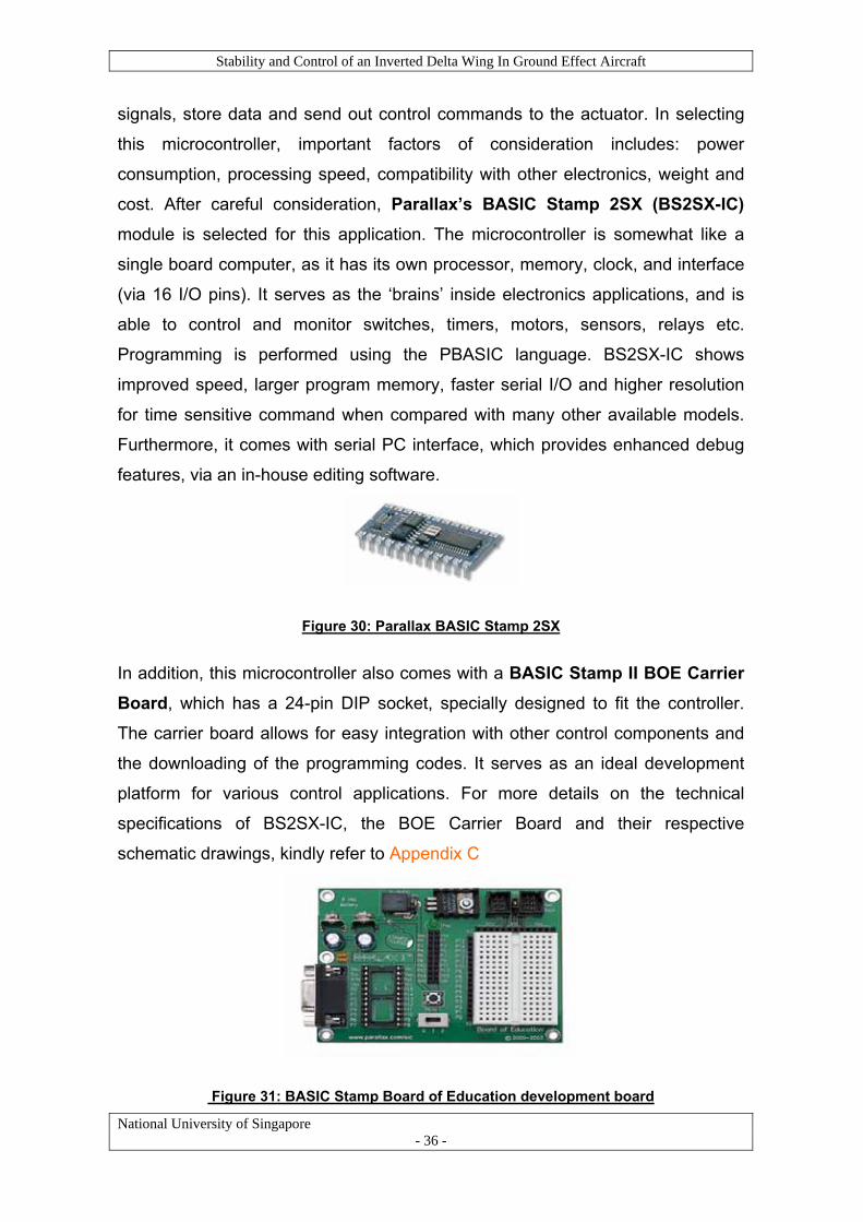
cost. After careful consideration, Parallax’s BASIC Stamp 2SX (BS2SX-IC) module is selected for this application. The microcontroller is somewhat like a
single board computer, as it has its own processor, memory, clock, and interface
(via 16 I/O pins). It serves as the ‘brains’ inside electronics applications, and is
able to control and monitor switches, timers, motors, sensors, relays etc.
Programming is performed using the PBASIC language. BS2SX-IC shows
improved speed, larger program memory, faster serial I/O and higher resolution
for time sensitive command when compared with many other available models.
Furthermore, it comes with serial PC interface, which provides enhanced debug
features, via an in-house editing software.
Figure 30: Parallax BASIC Stamp 2SX
In addition, this microcontroller also comes with a I BOE Carrier Board, which has a 24-pin DIP socket, specially designed to fit the controller.
BASIC Stamp I
The carrier board allows for easy integration with other control components and
the downloading of the programming codes. It serves as an ideal development
platform for various control applications. For more details on the technical
specifications of BS2SX-IC, the BOE Carrier Board and their respective
schematic drawings, kindly refer to Appendix C
Figure 31: BASIC Stamp Board of Education development board
National University of Singapore - 36 -

Stability and Control of an Inverted Delta Wing In Ground Effect Aircraft
National University of Singapore - 37 -
Finally, miscellaneous hardware requirements include a 6 – 9V DC battery jack,
which serves as the power source, and a USB to Serial Adapter to connect the
microcontroller to a PC or laptop for programming and troubleshooting functions.
The various hardware components are then interconnected and tested with the
servo to ensure compatibility, and verify that the microcontroller is able to send
precise signal pulses to the servo at regular interval. Different signal pulse widths
will result in here is to
calibrate the servo and obtain this relationship between pulse width and servo
ample of the program used in this experiment and the calibration data collected
the servo turning at different angles. As such, the objective
deflection angle. This is to ensure that the microcontroller is able to control and
turn the servo precisely through the angle range required. The amplitude, width
and frequency readings of the pulses are obtained using an oscilloscope. A
s
are shown in Appendix E and the pictures below illustrate the experimental
setup.
Figure 32 : Integrating the microcontroller with the servo to test for signals
6.1.2 Sensors A sensor has to be implemented to provide accurate altitude measurements and
feedback to the control loop. As the WIG aircraft is designed to fly at low altitude,
between 5 to 25cm, and at speed of approximately 12 to 15m/s, the sensor
chosen must have a sensing range capable of operating within this altitude and
speed limits, and a blind zone of less than 5cm. In addition, the sensor must be
able to function accur
e compatible with the other hardware components. After considering several
ately over both hard ground and water surface, and must
b

Stability and Control of an Inverted Delta Wing In Ground Effect Aircraft
National University of Singapore - 38 -
ensors, operating under different principles such as capacitive, photoelectric
de; as well as sensors with different scan techniques such as
s
and ultrasonic mo
thru-beam, retro-reflective and diffuse scan, the Parallax PING ultrasonic range finder - SRF08 is ultimately chosen. The sensor detects objects by emitting a
40kHz short ultrasonic burst and then "listening" for the echo. It has a sensing
range of between 3 cm to 3.3m and as such, provides good coverage for the
distance required. In addition, the PING sensor is designed by the same
company that develops the BASIC Stamp microcontroller and as such, offers
good hardware compatibility and easy integration.
Figure 33: PING ultrasonic sensor SRF08
Attached in Appendix C are some details involving the important features, theory
of operation and test data of this sensor.
A simple experiment is also designed to verify that the sensor is able to take
multiple readings, over both ground and water surface, and ensure its accuracy.
The setup shown below explains how the sensor is tested to take readings over
water surface at different height and across varying forward velocity.
Figure 34 : Experimental setup for testing the sensor
Ultrasonic Adjustable height Sensor
Water
Microcontroller

Stability and Control of an Inverted Delta Wing In Ground Effect Aircraft
National University of Singapore - 39 -
6.2 Software
6.3
The basic logic o rol the angle of
eflection of the elevator, in order to generate the required change in moment on
tail moment will result in a change in the angle of attack of
the aircraft and in turn produce a change in the height, to compensate for any
e is the most crucial
parameter, and the focus is thus to determine the moment of inertia along the
oment generated due to ∆α = ∆Lift on the tail x moment arm, lt
Coding
All programs are written in PBASIC programming language using the BAISC
Stamp Editor software v2.2. This software allows user to write and troubleshoot
programs on a PC or laptop, before downloading them into the BASIC stamp
microcontroller using a data cable. Syntax and reference manual on how to get
started with programming using PBASIC can be found at Parallax official
website. The various programs written for this project are attached in Appendix E
Establishing the Aerodynamics Transfer Function
f this automatic height control system is to cont
d
the tail. This change in
deviation from the ideal flying altitude, as stipulated by the control logic program.
To accomplish this function, it requires the calculation of the transfer function that
represents the aircraft dynamics.
To understand the motion dynamics of the WIG aircraft, it is important to first
determine its moment of inertia about the C.G. Since the objective is to
implement an automatic height control system, pitch angl
pitch axis (X-axis). To simplify the calculation, the entire aircraft is divided into 6
subassemblies, and each subassembly is then approximated to standard solid
shapes. Details of the calculation are shown in Appendix F.
The total moment of inertia about the pitch axis, Iyy of the model WIG aircraft is calculated to be 0.183 kgm2.
M
M(α) = - lt (∆Lift) = - lt (CLαt α Q St) = CMαt α Q St (21)
Where Q = 0.5 ρ U2 and St is the area of the tail Taking derivative with respect to α:

Stability and Control of an Inverted Delta Wing In Ground Effect Aircraft
dM /dα = CMαt Q St (22)
Note that the change in angle of attack, ∆α on an aft surface can be
approximated using small angle approximation:
tan∆α = q lt/U
National University of Singapore - 40 -
herefore for small angle, ∆α ≈ q lt/U
tribution due to pitching velocity (pitch rate) q:
(q) = - lt (CLαt ∆α Q St) = - lt [CLαt (q lt/U )Q St] (23)
n gov g the pitching motion can be derived as follows:
T
Now consider the moment con
M
Taking derivative with respect to q:
dM /dq = - lt [CLαt (lt/U )Q St] (24)
The equation of motio ernin
M = Iyy∆α&& (25)
Generally, pitching moment, M can also be expressed as a function of change in
ngle of attack, change in pitch rate and
hange in elevator deflection as shown below:
angle of attack, rate of change of a
c
M = f(∆α, ∆α& , ∆q, ∆δe) = (dM /dα) ∆α + (dM /dα& )∆α& + (dM /dq)∆q +(dM /dδe) ∆δe
(26)
Equating equation (25) and (26),
∆α&& - (Mq + Mα& ) ∆α& - Mα ∆α = Mδe ∆δe (27)
here Mq=(dM /dq)/ Iyy Mw α& =(dM /dα& )/ Iyy Mα = (dM /dα)/ Iyy Mδe = (dM /dδe)/ Iyy
and ∆q = ∆α&
Note that the moment contributions from the wings are neglected in the
s, the moment arm for the wings
ow taking Laplace Transform of equation (27),
formulation of the above equation. This is because all moment calculations are
taken with respect to the C.G position of the aircraft, which is very close to the
aerodynamic centre of pitch of the wings and thu
is very small, leading to negligible moment contributions.
N

Stability and Control of an Inverted Delta Wing In Ground Effect Aircraft
( )( ) ( ) ( ) eeq MsFMfsFMfsfsFs δδαα Δ=−−−−− )()()0(0 &
& (28) sM + 0()2 Note t 0( = . Also, the contribution due to in equation (28) is
to the interaction of the wing wake on
hat ))0( = ff & 0 α&M
ignored because this term is primarily due
an aft surface. This effect is negligible in this WIG aircraft configuration because
the tail is mounted at a high vertical location such that it is exposed to little
downwash.
Rearranging equation (28) yields:
[ ]
National University of Singapore - 41 -
V
U ∆α
h&Δ
eeq MMsMssF δδα Δ=−−)( 2
( )[ ] eeq MMsMss δα δα Δ=−−Δ 2
αδα
ss
qe
=ΔΔ )( (29)
Let the change in height due to the pitching moment be ∆h.
For small ang
δ
MsMM e
−−2
le, V ≈ U
UVh )sin(& (30)
quation
0),
Δ αα Δ=Δ=
Now taking Laplace Transform of e
(3
)()( sUshs αΔ=Δ
Dividing by ∆δe throughout, the transfer function becomes:
=ΔΔ
=ΔΔ
ee
ss
Ushδα
δ)()( )( 2
α
δ
MsMsM
sU
q
e
−− (31)
corresponding graphs,
C = - 0.0273 /°
Lαt
• Mδe = 0.0162 /°
From earlier results and
• Mαt
• C = 0.0578 /°

Stability and Control of an Inverted Delta Wing In Ground Effect Aircraft
National University of Singapore - 42 -
• St = 0.140 2
• Iyy = 0.183 kgm2
From equation (22) and (27),
Mα = CMαt Q St /Iyy = (-0.0273)(0.5x1.2 .14 183 = -1.824 /s2
From equation (24) and (27),
q t Lαt t t yy 2)(0.140)/0.183 = -0.0696 /s
Therefore the transfer function of the aircraft dynamics is:
m
x122)(0 0)/0.
M = - l [C (l /U)Q S ] /I
= -(0.465)(0.0578)(0.465/12)(0.5x1.2x12
⎥⎦⎤
⎢⎣⎡
++=⎥⎦
⎤⎢⎡=
s 016.0122⎣ +sse 0696.0 +Δ
Δssss
h824.10696.0
1944.0824.1
2)(23δ
m. Assuming a unit step input ⎟⎠⎞
⎜⎝⎛
s1This represents a 3rd order syste and taking
utput signal, ∆h(t) = L-1
inverse Laplace Transform:
)824.10696.0
1944.01( 23 ⎥⎦⎤
⎢O⎣ ss⎡
++ ss
e
Figure 35 below shows the block diagram of the automatic height control system
= )35.1sin(079.0)35.1cos(0041.000411066.0 0348.00348.0 tett tt −− −+−
.0
6.4 Overall Transfer Function of the System
Figure 35 : Block diagram representation of automatic height control system
K = 300 2)89.13( +s
9.192
n=1 sss 824.10696.0 23 ++
1944.0
Proportional
R(s) = h
1
Gain Servo
Elevator Aircraft Dynamics
Sensor
ref
+ E(s) V(s) θ(s) δ(s)
-
(0.1s +0.2s+1)
Compens
2
(0.32s2+0.6s+1)
ator
Controller
C(s) = hflight

Stability and Control of an Inverted Delta Wing In Ground Effect Aircraft
Notice that a proportional control, with a 4th order compensator, is implemented
in this system. The gain value, K, which is set at 300 for this model, can be
adjusted accordingly to obtain the ideal output response graph, with the desired
rise time, settling time and within the maximum percentage overshoot allowed.
A system is Bounded-input Bounded-output (BIBO) stable if whenever the input
signal r(t) is bounded, so is the output signal c(t). To verify the absolute stability
of this system and ensure that the output signal is bounded, Routh’s Stability
Criterion is used. This analysis technique helps to determine whether all the roots
in the characteristic equation of the closed loop transfer function have negative
National University of Singapore - 43 -
real p s the
the polynomial with
in the coefficients of
here is no sign change observed, it can be
the roots in the characteristic equation of the closed-loop
stability of the system, Root Locus plot
analysis is done using MATHLAB and the results are shown in Appendix G. The
arts and thus, lie in the open left half of the s-plane. This form
essential condition for BIBO system stability.
Considering the 5th order polynomial characteristic equation,
s5 + 39.37s4 + 489.16s3 + 2678.6s2 + 9351.85s + 11250 The Routh table is as follows:
s5 1 489.16 9351.85
s4 39.37 2678.6 11250
s3 421.12 9066.1 0
s2 1831.02 11250
s1 6478.69 0
s0 11250
Routh’s stability criterion states that the number of roots in
positive real parts is equal to the number of sign changes
the first column of the array. Since t
concluded that all
transfer function lie in the open left half s-plane, and the system enjoys absolute
stability.
In addition, to investigate the relative

Stability and Control of an Inverted Delta Wing In Ground Effect Aircraft
National University of Singapore - 44 -
lys e system’s unit response has a rise and settling time of
rox 0.25 and1.5 sec respectively, and the system is stable.
ana is shows that th
app imately
6.5 Implementation of the System
After selecting the necessary hardware components, writing the control algorithm
and determining the overall transfer function, the system is installed on board the
model aircraft, ready for testing.
trol system installed in the WIG aircraftFigure 36 : Automatic height con
The first stage of testing the system involves a static test in the laboratory as
shown in Figure 37 below.
Figure 37 : Static test on the automatic height control system
The sensor is attached to the underside of the inverted delta wing and height
readings are taken at varying altitude to test for the range of the sensor and
ccuracy itored
this
nsor is able to measure and provide accurate height
adings over the range of 3 to 50 cm, and is very responsive to any sudden
height changes. The corresponding response of the elevator deflection angle is
also very fast and precise. As such, it is concluded that the static performance of
the height control system is satisfactory.
a of the measurements. The deflection of the elevator is also mon
to ensure that the control logic is functioning properly. The results of
experiment show that the se
re

Stability and Control of an Inverted Delta Wing In Ground Effect Aircraft
National University of Singapore - 45 -
7 Flight Tests and Performance Evaluation
Flight tests are conducted over both hard ground and water surface to verify the
amphibious and ground effect characteristics of the WIG aircraft, and measure its
flight performance. This will also help to prove the accuracy of earlier simulation
sults. The
performance and effectiveness. Several videos are taken and it is evident that
command
effectively, and that there is no observable instability.
Outdoor hard ground testing locations include SRC running track and soccer
flight
performance, indoor testing is conducted
ed environment, the flight test results
evaluation parameters are
rol system is also found to
height.
35m swimming pool. The
arious tests show that the aircraft is able to sail and maneuver freely, un-stick
re automatic height control system is also tested to verify its
the aircraft is capable of achieving Ground Effect on both land and water.
7.1 Ground Testing
Numerous tests are done on different hard ground
surfaces to verify the ground effect on the model
WIG aircraft. Before each actual test flight, a control
and ground manoeuvring test is done to ensure that
the aircraft responds to the input control Figure 38 : Ground effect mode (Indoor hard ground testing)
field. However, when testing outdoor, the aircraft is often subjected to varying
wind and weather conditions. As such, the performance of the aircraft is found to
be inconsistent and unpredictable. This made the job of controlling the aircraft, in
response to changing flying conditions, extremely difficult and challenging. As
such the outdoor test flights are often unsustainable at the ideal flight speed and
altitude, while take off distance is also unpredictable. To improve on the
at MPSH, to eliminate environmental
variables. Given this enclosed and controll
showed significant improvements and performance
obtained more accurately. The automatic height cont
be effective in helping the aircraft attain the ideal flight
7.2 Testing on Water Surface
Flight tests over water surface are conducted at a
v

Stability and Control of an Inverted Delta Wing In Ground Effect Aircraft
itself from the water surface and take off after some
distance. Performance parameters are once again
evaluated. However, given external disturbances
such as varying wind and wave conditions, the
performance of the aircraft is less consistent and
piloting the aircraft is also more difficult.
7.3 Performance Evaluation Parameters
The main purpose of this section is to evaluate the performance of the WIG
aircraft and compare the results with theoretical expectations. The performance
parameters to be determined are: 1) Take off distance 2) Take off speed and
3) Cruising height
Figure 39 : Ground effect mode (Outdoor water testing)
Take off distance:
e is approximated by using
tests are conducted and it
gth of 3 dividers, which is
re kept
constant, as per the hard ground test. Due to the increase in drag experience by
ffected, and thus the required take off
deo footages taken during test flight.
f speed is very consistent among all
For the indoor hard ground testing, the take off distanc
the divider markings on the MPSH floor. Several flight
is observed consistently that the aircraft starts to lift
the ground effect mode after travelling about the len
approximately 20m. This take off distance is very muc
the test flights conducted.
In measuring the take off distance in water test, aircraft’s settings a
off the surface and get into
h consistent throughout all
the hull of the WIG aircraft, acceleration is a
distance increases accordingly. In addition, due to environmental variables, take
off distance also varies quite substantially, from about 22m to 26m.
Take off speed:
Take off speed is estimated by analysing vi
For hard ground testing, the average take of
test flights and is approximately 10m/s. This is close to earlier theoretical speed
estimation of about 12m/s required to lift the aircraft carrying the design payload.
National University of Singapore - 46 -

Stability and Control of an Inverted Delta Wing In Ground Effect Aircraft
For water testing, take off speed is approximately the same at about 10m/s, but a
longer runway is required to achieve that speed.
National University of Singapore - 47 -
ruising Height: C
The automatic height control system is used to evaluate the cruising height of the
aircraft. The on-board sensor is mounted under the wing, 5cm off the ground.
The sensor readings for indoor hard ground testing, obtained at regular intervals
of 0.5 sec, are plotted against flight time and shown in Figure 40 below. Height Readings From On-Board Sensor
(Hard Ground Testing) 12
0
2
4
6
0 2 4 6 8 10 12 14
Time into flight(s)
Heigh
t rea
ding
8
s (c
10
m)
Height readings
Figure 40 : Graph of height reading against time
g the electronics and throttling
the motor up to about 80% of its maximum speed.
: The aircraft gradually gathers straight line speed, which is
• 7 – 8 sec: The aircraft is lifted off the ground and is travelling at about 2
cm above ground s
• 8 – aircraft climbs gradually and stabilises at 5 cm off the
ground. Notice that the aircraft attains this ideal flight height about 2 sec
after activating the height control system. This is close to the theoretical
settling time of 1.5 sec as predicted by the transfer function model earlier.
• 10 to 15 sec: The height control system is disabled and the aircraft is
landed as it es to a complete
ed any longer due
to space limitation at the test ground.
ates the height
Aircraft stabilises at ideal height
Pilot activautomaticcontrol system
In Ground Effect Mode
Analysing the graph and looking at the different time periods:
• 0 – 3 sec: Setting up the aircraft, checkin
• 3 – 5 secnecessary to generate the required lift on the wings.
• 5 – 7 sec: The aircraft begins gliding over the ground surface at about
1cm height, in a straight, forward motion. The automatic height control
system is then enabled and takes over the control of the elevator.
urface.
10 sec: The
approaches the end of the test ground. It com
stop about 2 sec after landing. The flight is not sustain

Stability and Control of an Inverted Delta Wing In Ground Effect Aircraft
National University of Singapore - 48 -
The d
footag ven to be effective.
Similar ure 41 below.
ifferent time periods described above can be clearly seen from video
e taken. The automatic height control function is pro
ly for water testing, altitude readings are shown in FigHeight Readings From On-Board Sensor
(Water Testing)
0
2
4
6
0
Heigh
t rea
ding
s (c
Pilot activates the automatic height control system
Aircraft stabilises at height of 2cm above water
m)
Height readings
In Ground Effect Mode
2 4 6 8 10 12
Time into flight(s) Figure 41 : Graph of height reading against time
Analys
•
• raight line speed, while the
to about 2 cm above the surface.
raft is
landed. It comes to a complete stop almost immediately.
The effectiveness of the automatic height control function is not conclusive during
the water test, as the aircraft is unable to attain the ideal flight height of 5cm from
the surface. This is largely due mental conditions experienced
during test flights, which creates unpredictable disturbance, and makes the
controlling of the aircraft extremely difficult and challenging. External
disturbances have not been modelled into the height control system and as such
e system is unab put. Furthermore,
umption of the aircraft
flyin
contrib
ing the graph and looking at different time periods:
0 – 3 sec: Setting up the aircraft, checking the electronics and throttling
the motor up to its maximum speed.
3 – 6 sec: The aircraft gradually gathers st
automatic height control system is enabled.
• 6 – 9 sec: The aircraft is lifted off the water surface and climbs gradually
• 9 – 12 sec: The height control system is disabled and the airc
to varying environ
,
th le to response and compensate for such in
the height control system is modelled based on the ass
g over hard ground, rather than water surface. As such, this might have
uted to the discrepancies observed.

Stability and Control of an Inverted Delta Wing In Ground Effect Aircraft
National University of Singapore - 49 -
8 8.1 Pr
To fu lished at the start, it requires a
mu di
initial s ational software,
to the fabrication of the aircraft, and finally implementing a control system and
em with automatic height control
function, based on an understanding of the transfer function of the various
effectiveness of using CFD and GAMBIT to perform a
preliminary analysis on the WIG aircraft, and in designing the control
never have been possible without the relentless effort of every team
Project Conclusion and Recommendations for Further Study oject Conclusion
lfil the project objectives estab
lti sciplinary approach in engineering and design fundamentals. From the
tage of designing and simulating 3-D model using comput
conducting numerous flight tests, all the various stages require careful
consideration, testing and planning. The results obtained through simulations,
experiments and theoretical calculations are compared against test flight
performance and found to be reasonable and accurate. The stability and control
aspect of an Inverted Delta WIG aircraft is thoroughly investigated. In summary,
the achievements attained in this project include:
• Designing a workable WIG model aircraft, that is statically and dynamically
stable in the ground effect regime.
• Designing a complete control syst
control components and their time response characteristics.
• Demonstrating the
surfaces and horizontal tail stabilizer unit.
• Fabricating and assembling the model aircraft, and conducting flight tests.
• Performing land and water-based take offs, and directional manoeuvres.
• Demonstrating the amphibious nature and speed of a WIG aircraft, which
offer great potential in both military and commercial applications.
Lastly, this project has been enriching and extremely challenging, with many
hands-on experiences that serve to further enhance and verify fundamental
engineering concepts and theories learnt. The success of the project would
members.

Stability and Control of an Inverted Delta Wing In Ground Effect Aircraft
National University of Singapore - 50 -
8.2
With r scale model
airc f
perform
• s characteristic of the Inverted
,
• plementing a collision avoidance system, so as to enhance the
Future Directions
egards to this research area of ground effect on a small
ra t, more studies and investigations can be made to enhance its
ance. Recommendations for further research include:
An in depth analysis of the hydrodynamic
Delta WIG aircraft during the take off and landing mode,
• Designing an autopilot system that controls throttle speed and direction
allows compensation for external disturbances and can be integrated with
the current automatic height control function,
Im
capability of the WIG aircraft to be used over various terrain, and
• Investigating the effect of undesirable sea states and varying wind and
wave conditions on the performance and stability of the WIG aircraft.

Stability and Control of an Inverted Delta Wing In Ground Effect Aircraft
National University of Singapore - 51 -
List of References 1. Robert C. Nelson, “Flight Stability and Automatic Control”, 2nd edition
McGraw Hill, 1998
2. Ogata K, “Modern Control Engineering”, Prentice Hall N.J, USA, 1997 3. Maskalik, D. Sinitsyn, “EKRANOPLANS Peculiarity of the theory and
design”, St. Petersburg: Sudostroyeniye, 2000
4. Maskalik, D. Sinitsyn: “Amphistar First Civilian Ekranoplan”, St. Petersburg:
Sudostroyeniye, 2000
5. H.H. Chun, C.H Chang, “Longitudinal Stability and Dynamic Motions of a
small passenger WIG Craft”, Ocean Engineering 29, 2002, pp 1145-1162
6. Knud Benedict, Nikolai Kornev, Michael Meyer, Jost Ebert, “Complex
mathematical model of the WIG motion including the take-off mode”, Ocean
Engineering 29, 2002, pp 315-357
7. Nikolai Kornev, Konstantin Matveev, “Complex Numerical Modeling of
Dynamics and Crashes of Wing-In-Ground Vehicles”,AIAA,2003-600, pp 1-9
8. Nocola de Divitiss, “Performance and Stability of a Winged Vehicle in
Ground Effect”, Journal of Aircraft, Vol. 42, No. 1, 2005, pp 148-157
9. Staufenibel R. W., Schlichting U. J., “Stability of Airplanes in Ground Effect”,
Journal of Aircraft, Vol. 25, No. 4, 1998, pp 289-294

Stability and Control of an Inverted Delta Wing In Ground Effect Aircraft
Appendix A: Aerodynamic Coefficients Data and Graphs The aerodynamic coefficients are obtained with the aid of CFD simulation
software FLUENT and 3-D modelling software GAMBIT. The simulations are
repeated for several angles of attack (AOA), under ideal flying height and
velocity, and the readings obtained are plotted accordingly. The equations of the
plotted graphs reveal important aerodynamic coefficients. The criteria for static
stability, as stated in equation (1), (2), (3) and (6) are then analysed by
processing the simulation results obtained, to determine the required parameters
and coefficient derivatives.
For Wing Alone / Wing plus Hull Configuration:
Coefficient of Lift (CL) vs. Angle of Attack(For Anhedral Angle = 8, h/c = 0.1, Wing angle of incidence = 4)
y = 0.0559x + 0.0846
y = 0.0696x + 0.1007
-0.4
-0.2
0
0.2
0.4
0.6
0.8
1
-7 -6 -5 -4 -3 -2 -1 0 1 2 3 4 5 6 7 8 9 10
Angle of Attack
Coe
ffici
ent o
f Lift
(CL)
Wing Alone: AA =8, h/c = 0.1Wing + Hull AA = 8, h/c =0.1Wing Alone (AA = 8, h/c=0.1)Wing + Hull (AA = 8, h/c = 0.1)
National University of Singapore - 52 -

Stability and Control of an Inverted Delta Wing In Ground Effect Aircraft
Coefficient of Drag (CD) vs. Angle of Attack(For Anhedral Angle = 8, h/c = 0.1 Wing angle of incidence = 4)
y = 0.0004x2 + 0.0004x + 0.0096
y = 0.0006x2 + 0.0004x + 0.0151
0
0.005
0.01
0.015
0.02
0.025
0.03
0.035
0.04
0.045
0.05
0.055
0.06
0.065
-7 -5 -3 -1 1 3 5 7 9
Angle of Attack
Coe
ffici
ent o
f Dra
g (C
D)
Wing alone: AA = 8, h/c = 0.1Wing + hull: AA=8, h/c=0.1Wing alone: AA = 8, h/c =0.1Wing + hull: AA=8, h/c=0.1
Coefficient of Moment (CM) vs. Angle of Attack(For Anhedral Angle = 8, h/c = 0.1 Wing angle of incidence = 4)
y = 0.0082x - 0.0178
y = 0.0118x - 0.0229
-0.5
-0.4
-0.3
-0.2
-0.1
0
0.1
0.2
0.3
0.4
-8 -6 -4 -2 0 2 4 6 8 10
Angle of Attack
Coe
ffici
ent o
f Mom
ent (
CM)
Wing alone: AA = 8, h/c = 0.1
Wing + hull: AA=8, h/c=0.1
Wing alone: AA = 8, h/c =0.1
Wing + hull: AA=8, h/c=0.1
National University of Singapore - 53 -

Stability and Control of an Inverted Delta Wing In Ground Effect Aircraft
For Tail Alone Configuration:
Coefficient of Lift (CL) vs. Angle of Attack
y = 0.0578x + 0.1719
-0.4
-0.2
0
0.2
0.4
0.6
0.8
1
-4 -3 -2 -1 0 1 2 3 4 5 6 7
Angle of Attack
Coe
ffici
ent o
f Lift
(CL)
Tail Alone: h/c = 0.1Tail Alone ( h/c=0.1)
Coefficient of Drag (CD) vs. Angle of Attack
y = 0.0005x2 + 0.0019x + 0.0227
0
0.005
0.01
0.015
0.02
0.025
0.03
0.035
0.04
0.045
0.05
0.055
-7 -5 -3 -1 1 3 5 7 9
Angle of Attack
Coe
ffici
ent o
f Dra
g (C
D)
Tail alone: h/c = 0.1Tail alone: h/c =0.1
National University of Singapore - 54 -

Stability and Control of an Inverted Delta Wing In Ground Effect Aircraft
Coefficient of Moment (CM) vs. Angle of Attack
y = -0.0273x + 0.0851
-1
-0.8
-0.6
-0.4
-0.2
0
0.2
0.4
-5 -3 -1 1 3 5 7 9 11 13 15 17
Angle of Attack
Coe
ffici
ent o
f Mom
ent (
CM)
Tail alone: h/c = 0.1Tail alone: h/c =0.1
For Elevator:
Lift generated on Horizontal Tail vs. Elevator Deflection Angle
y = -0.0295x - 0.1524
-1.4
-1.2
-1
-0.8
-0.6
-0.4
-0.2
0
0.2
0.4
0.6
0.8
1
-22 -20 -18 -16 -14 -12 -10 -8 -6 -4 -2 0 2 4 6 8 10 12
Deflection Angle
Lift
gene
rate
d (N
)
Elevator
Elevator
National University of Singapore - 55 -

Stability and Control of an Inverted Delta Wing In Ground Effect Aircraft
Moment generated by Horizontal Tail vs. Elevator Deflection Angle
y = 0.0162x - 0.0173
-0.4
-0.35
-0.3
-0.25
-0.2
-0.15
-0.1
-0.05
0
0.05
0.1
0.15
0.2
0.25
0.3
0.35
0.4
-22 -20 -18 -16 -14 -12 -10 -8 -6 -4 -2 0 2 4 6 8 10 12
Deflection Angle
Mom
ent g
ener
ated
(N
m)
Elevator
Linear (Elevator)
For Rudder:
Force on Rudder vs. Deflection Angle
y = -0.0527x
-0.4
-0.3
-0.2
-0.1
0
0.1
0.2
0.3
0.4
0.5
0.6
0.7
0.8
-12 -10 -8 -6 -4 -2 0 2 4 6 8
Deflection Angle
Forc
e ge
nera
ted
due
to ru
dder
def
lect
ion
(N)
Rudder Rudder
National University of Singapore - 56 -

Stability and Control of an Inverted Delta Wing In Ground Effect Aircraft
Moment generated by Rudder vs. Deflection Angle
y = 0.0254x
-0.8
-0.7
-0.6
-0.5
-0.4
-0.3
-0.2
-0.1
0
0.1
0.2
0.3
0.4
0.5
0.6
-10 -8 -6 -4 -2 0 2 4 6 8 10
Deflection Angle
Mom
ent g
ener
ated
due
to ru
dder
def
lect
ion
(Nm
)
Rudder Rudder
National University of Singapore - 57 -

Stability and Control of an Inverted Delta Wing In Ground Effect Aircraft
Appendix B: Servo Specifications
National University of Singapore - 58 -

Stability and Control of an Inverted Delta Wing In Ground Effect Aircraft
Appendix C: Microcontroller and Sensor Specifications
BASIC Stamp 2sx – IC Schematic Drawing
National University of Singapore - 59 -

Stability and Control of an Inverted Delta Wing In Ground Effect Aircraft
National University of Singapore - 60 -

Stability and Control of an Inverted Delta Wing In Ground Effect Aircraft
National University of Singapore - 61 -

Stability and Control of an Inverted Delta Wing In Ground Effect Aircraft
Board of Education Schematic Drawing
National University of Singapore - 62 -

Stability and Control of an Inverted Delta Wing In Ground Effect Aircraft
National University of Singapore - 63 -

Stability and Control of an Inverted Delta Wing In Ground Effect Aircraft
National University of Singapore - 64 -

Stability and Control of an Inverted Delta Wing In Ground Effect Aircraft
National University of Singapore - 65 -

Stability and Control of an Inverted Delta Wing In Ground Effect Aircraft
National University of Singapore - 66 -
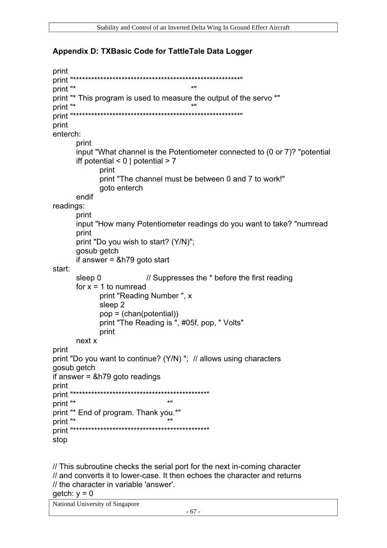
Stability and Control of an Inverted Delta Wing In Ground Effect Aircraft
National University of Singapore - 67 -
Appendix D: TXBasic Code for TattleTale Data Logger print print "*******************************************************" print "* *" print "* This program is used to measure the output of the servo *" print "* *" print "*******************************************************" print enterch: print input "What channel is the Potentiometer connected to (0 or 7)? "potential iff potential < 0 | potential > 7 print print "The channel must be between 0 and 7 to work!" goto enterch endif readings: print input "How many Potentiometer readings do you want to take? "numread print print "Do you wish to start? (Y/N)"; gosub getch if answer = &h79 goto start start: sleep 0 // Suppresses the * before the first reading for x = 1 to numread print "Reading Number ", x sleep 2 pop = (chan(potential)) print "The Reading is ", #05f, pop, " Volts" print next x print print "Do you want to continue? (Y/N) "; // allows using characters gosub getch if answer = &h79 goto readings print print "********************************************" print "* *" print "* End of program. Thank you.*" print "* *" print "********************************************" stop // This subroutine checks the serial port for the next in-coming character // and converts it to lower-case. It then echoes the character and returns // the character in variable 'answer'. getch: y = 0

Stability and Control of an Inverted Delta Wing In Ground Effect Aircraft
National University of Singapore - 68 -
wait: itext y,0 if y = 0 goto wait // waits until a is key pressed y = 0 answer = get(y) | &h20 // convert to upper case print \answer // echo the answer return End code

Stability and Control of an Inverted Delta Wing In Ground Effect Aircraft
National University of Singapore - 69 -
Appendix E: Microcontroller Programming Source Codes
E-1: Program for Servo Calibration
E-2: Program for Testing Activation Command
E-3: Program for Sensor Readings
E-4: Program for Reading, Storing and Displaying Data
E-5: Program for Automatic Height Control Function

Stability and Control of an Inverted Delta Wing In Ground Effect Aircraft
National University of Singapore - 70 -
Appendix E-1: Program for Servo Calibration 'This program is written for configuring the servo. By varying the input pulse, it determines the corresponding angle of deflection on the servo and test for its responsiveness ' {$STAMP BS2sx} ' {$PBASIC 2.5} pulseWidth VAR Word ElevServo CON 12 FREQOUT 2, 2000, 3000 ' Signal program start/reset. DEBUG "Start" DO DEBUG "Enter pulse width: " ' vary pulse width to calibrate servo DEBUGIN DEC pulseWidth PULSOUT ElevServo, pulseWidth PAUSE 10 LOOP
Table 5: Servo calibration readings
Input Readings Pulse Width (ms) Servo Deflection Angle (°) Direction 1875 1.500 0 No Rotation 1925 1.540 3 CW 2075 1.660 12 CW 2125 1.700 15 CW 2175 1.740 18 CW 1825 1.460 3 CCW 1675 1.340 12 CCW 1475 1.180 24 CCW 1375 1.100 30 CCW

Stability and Control of an Inverted Delta Wing In Ground Effect Aircraft
National University of Singapore - 71 -
Appendix E-2: Program for Testing Activation Command ‘This program is written to test out the difference in reading between an On and Off state command from the remote controller. Channel 5 on the remote controller is used as the dedicated on/off relay switch. ' {$STAMP BS2sx} ' {$PBASIC 2.5} Ch5 CON 15 'Activation input Elev VAR Word DO PULSIN Ch5,1,Elev ' Read activation command DEBUG CR, “The reading is: “ DEBUG SDEC Elev PAUSE 2000 LOOP

Stability and Control of an Inverted Delta Wing In Ground Effect Aircraft
National University of Singapore - 72 -
Appendix E-3: Program for Sensor Readings
‘This program is written to obtain altitude readings while the aircraft is in flight. Note that the interval at which the height readings at taken can be adjusted accordingly. ' {$STAMP BS2sx} ' {$PBASIC 2.5} ' -----[ DATA Directives ]---------------------------------------------------- Records DATA (101) RecordsEnd DATA ' -----[ I/O Definitions ]------------------------------------------------- Ping PIN 15 ' -----[ Constants ]------------------------------------------------------- #SELECT $STAMP #CASE BS2, BS2E Trigger CON 5 ' trigger pulse = 10 uS Scale CON $200 ' raw x 2.00 = uS #CASE BS2SX, BS2P, BS2PX Trigger CON 13 Scale CON $0CD ' raw x 0.80 = uS #CASE BS2PE Trigger CON 5 Scale CON $1E1 ' raw x 1.88 = uS #ENDSELECT RawToIn CON 889 ' 1 / 73.746 (with **) RawToCm CON 2257 ' 1 / 29.034 (with **) IsHigh CON 1 ' for PULSOUT IsLow CON 0 ' -----[ EEPROM Data ]----------------------------------------------------- FREQOUT 2, 5000, 4000 ' -----[ Variables ]------------------------------------------------------- char VAR Byte eeIndex VAR Word value VAR Word rawDist VAR Word ' raw measurement inches VAR Word cm VAR Word

Stability and Control of an Inverted Delta Wing In Ground Effect Aircraft
National University of Singapore - 73 -
' -----[ Initialization ]-------------------------------------------------- Reset: DEBUG CLS, ' setup report screen "Parallax Ping Sonar ", CR, "=====================", CR, CR, "Time (uS)..... ", CR, "Inches........ ", CR, "Centimeters... " ' -----[ Program Code ]---------------------------------------------------- Main: FOR eeIndex = Records TO RecordsEnd STEP 2 ‘take 15 readings GOSUB Get_Sonar ' get sensor value inches = rawDist ** RawToIn ' convert to inches cm = rawDist ** RawToCm ' convert to centimeters value = cm WRITE eeIndex, Word value DEBUG CRSRXY, 15, 3, ' update report screen DEC rawDist, CLREOL, CRSRXY, 15, 4, DEC inches, CLREOL, CRSRXY, 15, 5, DEC cm, CLREOL PAUSE 500 NEXT DEBUG CR, "End of records." FREQOUT 2, 3000, 3000 END ' -----[ Subroutines ]----------------------------------------------------- Get_Sonar: Ping = IsLow ' make trigger 0-1-0 PULSOUT Ping, Trigger ' activate sensor PULSIN Ping, IsHigh, rawDist ' measure echo pulse rawDist = rawDist */ Scale ' convert to uS rawDist = rawDist / 2 ' remove return trip RETURN

Stability and Control of an Inverted Delta Wing In Ground Effect Aircraft
National University of Singapore - 74 -
Appendix E-4: Program for Reading, Storing and Displaying Data 'This program demonstrates storing, retrieving and erasing values in EEPROM memory. ' Values are obtained at pre-determined intervals using the PING sonar sensor '{$STAMP BS2sx} '{$PBASIC 2.5} ' -----[ DATA Directives ]---------------------------------------------------- Records DATA (101) RecordsEnd DATA ' -----[ Variables ]---------------------------------------------------------- char VAR Byte eeIndex VAR Word value VAR Word avg VAR Word total VAR Word rawDist VAR Word ' raw measurement inches VAR Word cm VAR Word counter VAR Word ' -----[ I/O Definitions ]------------------------------------------------- Ping PIN 15 ' -----[ Constants ]------------------------------------------------------- #SELECT $STAMP #CASE BS2, BS2E Trigger CON 5 ' trigger pulse = 10 uS Scale CON $200 ' raw x 2.00 = uS #CASE BS2SX, BS2P, BS2PX Trigger CON 13 Scale CON $0CD ' raw x 0.80 = uS #CASE BS2PE Trigger CON 5 Scale CON $1E1 ' raw x 1.88 = uS #ENDSELECT RawToIn CON 889 ' 1 / 73.746 (with **) RawToCm CON 2257 ' 1 / 29.034 (with **) IsHigh CON 1 ' for PULSOUT IsLow CON 0 ' -----[ Main Routine ]-------------------------------------------------------

Stability and Control of an Inverted Delta Wing In Ground Effect Aircraft
National University of Singapore - 75 -
DO DEBUG CLS, "Type C, R or D", CR, "C - Clear records", CR, "R - Record records", CR, "D - Display records", CR, ">" DEBUGIN char DEBUG CR SELECT char CASE "C", "c" GOSUB Clear_Data CASE "R", "r" GOSUB Record_Data CASE "D", "d" GOSUB Display_Data CASE ELSE DEBUG CR, "Not a valid entry.", CR, "Try again." PAUSE 1500 ENDSELECT LOOP ' -----[ Subroutine - Clear_Data ]-------------------------------------------- Clear_Data: FOR eeIndex = Records TO RecordsEnd WRITE eeIndex, 100 NEXT DEBUG CR, "Records cleared." PAUSE 1000 RETURN ' -----[ Subroutine - Record_Data ]------------------------------------------- Record_Data: FOR eeIndex = Records TO RecordsEnd STEP 2 GOSUB Get_Sonar ' get sensor value inches = rawDist ** RawToIn ' convert to inches cm = rawDist ** RawToCm ' convert to centimeters value = cm WRITE eeIndex, Word value DEBUG CR, "Recording..." NEXT DEBUG CR, "End of records.",

Stability and Control of an Inverted Delta Wing In Ground Effect Aircraft
National University of Singapore - 76 -
CR, "Press Enter for menu..." DEBUGIN char RETURN ' -----[ Subroutine - Display_Data ]------------------------------------------ Display_Data: DEBUG CR, "Index Record", CR, "----- ------", CR FOR eeIndex = Records TO RecordsEnd STEP 2 READ eeIndex, Word value DEBUG DEC eeIndex, CRSRX, 7, SDEC value, CR NEXT total = 0 ' Initialising FOR eeIndex = Records TO RecordsEnd STEP 2 READ eeIndex, Word value total = total + value NEXT avg = total / 50 DEBUG CR, "The average is: " DEBUG SDEC avg DEBUG CR, "Press Enter for menu..." DEBUGIN char RETURN ' -----[ Subroutine - Get_Sonar ]------------------------------------------- Get_Sonar: Ping = IsLow ' make trigger 0-1-0 PULSOUT Ping, Trigger ' activate sensor PULSIN Ping, IsHigh, rawDist ' measure echo pulse rawDist = rawDist */ Scale ' convert to uS rawDist = rawDist / 2 ' remove return trip PAUSE 500 RETURN

Stability and Control of an Inverted Delta Wing In Ground Effect Aircraft
National University of Singapore - 77 -
Appendix E-5: Program for Automatic Height Control Function ‘This program is used to maintain the aircraft at the ideal flying altitude of 11cm, by controlling the elevator servo ' {$STAMP BS2sx} ' {$PBASIC 2.5} ' -----[ DATA Directives ]---------------------------------------------------- Records DATA (101) RecordsEnd DATA ' -----[ I/O Definitions ]------------------------------------------------- Ping PIN 15 Ch2 CON 12 ' Elevator channel Ch5 CON 14 ' Channel used to enable autopilot ElevServo CON 13 ' -----[ Constants ]------------------------------------------------------- #SELECT $STAMP #CASE BS2, BS2E Trigger CON 5 ' trigger pulse = 10 uS Scale CON $200 ' raw x 2.00 = uS #CASE BS2SX, BS2P, BS2PX Trigger CON 13 Scale CON $0CD ' raw x 0.80 = uS #CASE BS2PE Trigger CON 5 Scale CON $1E1 ' raw x 1.88 = uS #ENDSELECT RawToIn CON 889 ' 1 / 73.746 (with **) RawToCm CON 2257 ' 1 / 29.034 (with **) IsHigh CON 1 ' for PULSOUT IsLow CON 0 ' -----[ EEPROM Data ]----------------------------------------------------- FREQOUT 2, 1000, 3000 ' -----[ Variables ]------------------------------------------------------- char VAR Byte eeIndex VAR Word value VAR Word rawDist VAR Word ' raw measurement

Stability and Control of an Inverted Delta Wing In Ground Effect Aircraft
National University of Singapore - 78 -
inches VAR Word cm VAR Word counter_1 VAR Word counter_2 VAR Word counter_3 VAR Word counter_4 VAR Word counter_5 VAR Word Temp VAR Word Elev VAR Word ' -----[ Initialization ]-------------------------------------------------- Reset: DEBUG CLS, ' setup report screen "Parallax Ping Sonar ", CR, "=====================", CR, CR, "Time (uS)..... ", CR, "Inches........ ", CR, "Centimeters... " ' -----[ Program Code ]---------------------------------------------------- Main: FOR eeIndex = Records TO RecordsEnd STEP 2 GOSUB Get_Sonar ' get sensor value inches = rawDist ** RawToIn ' convert to inches cm = rawDist ** RawToCm ' convert to centimeters value = cm WRITE eeIndex, Word value DEBUG CRSRXY, 15, 3, ' update report screen DEC rawDist, CLREOL, CRSRXY, 15, 4, DEC inches, CLREOL, CRSRXY, 15, 5, DEC cm, CLREOL PULSIN Ch2,1,Elev ' Read Elevator command PULSIN Ch5,1,Temp ' Read enable command IF (Temp > 1800) THEN GOSUB Enabled ELSE PULSOUT ElevServo,Elev ENDIF

Stability and Control of an Inverted Delta Wing In Ground Effect Aircraft
National University of Singapore - 79 -
PAUSE 500 NEXT DEBUG CR, "End of records." END ' -----[ Subroutines ]----------------------------------------------------- Get_Sonar: Ping = IsLow ' make trigger 0-1-0 PULSOUT Ping, Trigger ' activate sensor PULSIN Ping, IsHigh, rawDist ' measure echo pulse rawDist = rawDist */ Scale ' convert to uS rawDist = rawDist / 2 ' remove return trip RETURN Enabled: IF (cm = 10) THEN GOSUB Elevator_neutral ELSEIF (cm = 11) OR (cm = 12) THEN GOSUB Elevator_down_1 ELSEIF (cm > 13) THEN GOSUB ELevator_down_2 ELSEIF (cm = 9) OR (cm = 8) THEN GOSUB Elevator_up_1 ELSEIF (cm < 7) THEN GOSUB Elevator_up_2 ELSE HIGH 10 PAUSE 500 LOW 10 PAUSE 500 ENDIF RETURN Elevator_neutral: FOR counter_1 = 1 TO 100 PULSOUT ElevServo, 1875 ' Hold servo at neutral position PAUSE 12
Stability and Control of an Inverted Delta Wing In Ground Effect Aircraft
National University of Singapore - 80 -
NEXT RETURN Elevator_down_1: FOR counter_2 = 1 TO 100 PULSOUT ElevServo, 1775 ' Servo turn ccw 6 deg PAUSE 12 NEXT RETURN Elevator_down_2: FOR counter_3 = 1 TO 100 PULSOUT ElevServo, 1675 ' Servo turn ccw 12 deg PAUSE 12 NEXT RETURN Elevator_up_1: FOR counter_4 = 1 TO 100 PULSOUT ElevServo, 1975 ' Servo turn cw 6 deg PAUSE 11 NEXT RETURN Elevator_up_2: FOR counter_5 = 1 TO 100 PULSOUT ElevServo, 2075 ' Servo turn cw 12 deg PAUSE 11 NEXT RETURN

Stability and Control of an Inverted Delta Wing In Ground Effect Aircraft
National University of Singapore - 81 -
Appendix F: Moment of Inertia Calculation Assuming homogenous mass distribution for all subassemblies:
Table 6: Moment of inertia calculations
Subassembly Standard shape
Mass (kg)
Distance from ideal CG, d (m) Dimension
(m) Moment of Inertia Eqn, Iyy
Moment of
Inertia, Iyy
(kgm2)
Hull + Top Cover
Circular Cylinder (radius a height h)
0.496 0.040 a = 0.075 h = 0.81
1/12 M (h2 + 3a2) + Md2 0.0286
Horizontal Tail + Servo
Elliptical Cylinder
(Major axis radius a
Minor axis radius b)
0.271 0.465 a = 0.1075 b = 0.04
¼ M(a2 + b2) + Md2 0.0570
Battery + ESC (x 02)
Rectangular Box (depth a
length L)
0.206 x 2 0.230 a = 0.035
L = 0.15 [1/12 M (a2 + L2) + Md2] x 2 0.0226
Motor Mount Rectangular Plate(width a) 0.085 0.186
a = 0.035
1/12 Ma2 + Md2 0.0054
Motor + Propeller
(x 02)
Circular Cylinder (radius a height h)
0.144 x 2 0.193 a = 0.02
h = 0.065 [1/12 M (h2 +
3a2) + Md2] x 2 0.0111
Wings
Half Circular Conical Shell (base radius r height h)
0.406 0.110 r = 0.37 h = 0.76
1/4 Mr2 + 1/6 Mh2 + Md2 0.0579
Total: 2.027 0.183

Stability and Control of an Inverted Delta Wing In Ground Effect Aircraft
Appendix G: Root Locus and Bode Plot
National University of Singapore - 82 -