mcao laser launch telescope and periscope celine d’orgeville and jim catone
TRANSCRIPT

MCAOMCAO
Laser Launch Laser Launch TelescopeTelescope
and Periscopeand Periscope
Celine d’Orgeville and Jim Catone

May 24-25, 2001 MCAO Preliminary Design Review
2
MCAOMCAO
• On-axis, behind secondary mirror
• Do not obstruct secondary mirror central hole when MCAO not in use
CoDR: deployable primary mirror
LLTLLT
PDR: PERISCOPE

May 24-25, 2001 MCAO Preliminary Design Review
3
MCAOMCAOLLT requirementsLLT requirements
Parameter SpecificationMagnification ratio
60 with a 1% tolerance
Field of View+/- 1.2 arcmin (unvignetted)+/- 1.0 arcmin (for image quality spec.)
Optical design No central obscurationNo internal focus~ 450mm STOP
Focus adjustmentFixed afocal telescope (passive comp. preferred)
Optical transmission
> 97 % @ 589nm~ 50 % in the visible (450-700nm)
Optics and coatings
Can sustain power densities in the 500-1000 W/cm2 range

May 24-25, 2001 MCAO Preliminary Design Review
4
MCAOMCAOLLT image quality analysis for LLT image quality analysis for MCAOMCAO
• LGS WFS centroiding measurement error must not increase by more than 20% (req.)/ 10% (goal)
Low order aberrations• LGS spot size
increase < 10% (5%)• Defocus <0.1
wave rms• Astig <0.18 wave
rms• Coma <0.1 wave rms• Trefoil <0.25 wave
rms• Spherical <0.1 wave
rms
High order aberrations• Decrease in SNR < 10%
(5%)
• High order ab. <0.06 wave rms

May 24-25, 2001 MCAO Preliminary Design Review
5
MCAOMCAO
LLT image quality specs for MCAOLLT image quality specs for MCAO
Wavefront aberrations
Requirement Goal
Tip/Tilt ( dynamic) < 0.1 Hz 0.1-1 Hz 1-30 Hz > 30 Hz
(in arcsec on the sky) < 10’’ peak < 1’’ peak < 0.2’’ peak < 0.03’’ rms
Low order aberrations < 0.15 wave rms < 0.1 wave rms
High order aberrations < 0.06 wave rms < 0.04 wave rms
All other performance being equal, this would save a 15% increase in laser power requirement

May 24-25, 2001 MCAO Preliminary Design Review
6
MCAOMCAO
LLT optical designLLT optical design
16mm toroidal fold mirror
10mm silica aspheric
lens
450mm, f=1672.3mm, 258mm
off-axis parabola

May 24-25, 2001 MCAO Preliminary Design Review
7
MCAOMCAOOptical perf. over ±1 arcmin FoVOptical perf. over ±1 arcmin FoVfor a uniformly illuminated 450mm for a uniformly illuminated 450mm STOPSTOP

May 24-25, 2001 MCAO Preliminary Design Review
8
MCAOMCAOOptical perf. over ±1 arcmin FoVOptical perf. over ±1 arcmin FoVfor a uniformly illuminated 300mm for a uniformly illuminated 300mm STOPSTOP

May 24-25, 2001 MCAO Preliminary Design Review
9
MCAOMCAOEncircled energy over ±1.2 arcmin Encircled energy over ±1.2 arcmin FoVFoV

May 24-25, 2001 MCAO Preliminary Design Review
10
MCAOMCAOGemini Telescope’sGemini Telescope’sTop End AssemblyTop End Assembly
Mounting SurfaceFor the LLT
Electronics Boxes
f/16 Top End
SecondaryMirror Module
Secondary SupportStructure (SSS)
Top End Vanes
Vane Ring
SSS/M2Interface
Plane

May 24-25, 2001 MCAO Preliminary Design Review
11
MCAOMCAOGemini Telescope’sGemini Telescope’sSecondary Support Secondary Support
StructureStructure
3D Viewof the SSS
ReferencePlane
475.0
1084.0±7.0
2148.0
2153.0
2348.0
2323.0
2178.0
25.0
• Figures taken from drawings ICR01 and ICR02

May 24-25, 2001 MCAO Preliminary Design Review
12
MCAOMCAO
SSS/LLT/BTOOB AlignmentSSS/LLT/BTOOB Alignment
• First align the BTOOB to the LLT and pin• Remove the BTOOB and loosely install the LLT in the
SSS• Reinstall the BTOOB on the LLT• Align the BTOOB/LLT assembly with the SSS• Remove the BTOOB and pin the LLT/SSS interface• Finally, reinstall the BTOOB
Secondary Support
Structure
Laser Launch
Telescope
Beam Transfer Optics Optical Bench

May 24-25, 2001 MCAO Preliminary Design Review
13
MCAOMCAO
4X LLT/SSS Interface Pad
LLT Top Plate InterfacesLLT Top Plate Interfaces
3X LLT/BTOOB Interface Pad
F910.0
F500.0
2X LLT/SSS Location PinAccess Port
+X
-X
+Y
-Y
2X LLT/BTOOBAlignment
PinLocation
PLAN VIEW

May 24-25, 2001 MCAO Preliminary Design Review
14
MCAOMCAO
LLT Interface DetailsLLT Interface Details
LLT/SSS Alignment LLT/BTOOB Alignment
SSS Top
Plate M20 Nut&
Washer
½” Locating Pin
1.0 mm Raised Pad5.0 mm Thick Shim
BTOOpticalBenchLLT Top
Platew/ M20 Stud
LLT Pilot HoleAccess Port
1.0 mm Raised Pads
¼” Locating Pin
M12 Bolt& Washer
M12 Threaded Insert
15.0
24.0
25.0

May 24-25, 2001 MCAO Preliminary Design Review
15
MCAOMCAOPassive Focus Passive Focus Compensation Compensation ConfigurationConfiguration
258.0 Off-Axis Distance
1682.31631.5
DETAIL 1
1 Fold MirrorDivergingLens
Incoming Beam
Translation Table
Compensation
RodTheoretical MirrorMounting Plane
Exiting Beam
• Produces a maximum error of 2.5 nm in the temperature range of 0 ± 15°

May 24-25, 2001 MCAO Preliminary Design Review
17
MCAOMCAOPeriscopePeriscope
• Why ?– 168mm M2 hole to avoid narcissus effect when
observing in thermal IR– M2 hole blocked by LLT, IR instrument can no longer see
sky
• How ?– Two-mirror periscope to divert the beam around the SSS– Mirror cover to block beam during visible observations– Oversized FoV and STOP to allow for M2 tip/tilt and
decentrations and telescope flexures
• Where ?– Bottom of SSS– Replace Gemini central baffle
• Who ?– Gemini designs, integrates and commissions – RFP for parts for GN and GS periscopes

May 24-25, 2001 MCAO Preliminary Design Review
18
MCAOMCAO
Periscope Optical DesignPeriscope Optical Design
180mm Hole in M2(Actual Hole is
168 mm)
Focus Target at Height of BTOOB/LLT Assembly
PM2 ParentMirror
PM1 ParentMirror
8M TelescopeAxis
= 10°±1°
3.5° to 4.5° Exclusion Angle on the Sky

May 24-25, 2001 MCAO Preliminary Design Review
19
MCAOMCAO
Secondary Mirror Bracket
Mirror Cover
Assembly
Primary Mirror Bracket
Primary Mirror
Secondary Mirror
Periscope SubsystemPeriscope Subsystem

May 24-25, 2001 MCAO Preliminary Design Review
20
MCAOMCAOPeriscope Location (SSS)Periscope Location (SSS)
SSS Cross Bracing
Periscope
Assembly
SSS
Top End Vane Interface

May 24-25, 2001 MCAO Preliminary Design Review
22
MCAOMCAOPeriscope Location (M2)Periscope Location (M2)
f/16 SecondaryMirror (M2)
M2 PositioningMechanism
M2 Tilt Mechanism
475.035.0
897.0
Beam Path
Periscope Assembly
LLT
168 mm Optical Stop
SSS
M2 Mounting Plate

May 24-25, 2001 MCAO Preliminary Design Review
24
MCAOMCAOPeriscope Mirror Periscope Mirror
MountingMounting
115° Offset
Spherical Mount
Secondary
Bracket Flange
PrimaryMirror
Primary Mirror Bracket
Axis of Symmetry

May 24-25, 2001 MCAO Preliminary Design Review
26
MCAOMCAO
Periscope Mirror CoverPeriscope Mirror Cover
Secondary Mirror
Mirror Cover Motor Bracket
Mirror Cover Motor
Aluminum Hinge
Mirror Cover 2-Bar
Linkage
Secondary Mirror Bracket

May 24-25, 2001 MCAO Preliminary Design Review
28
MCAOMCAO
Mass AllocationMass Allocation
Total Mass Addedto the SSS125 ±25 kg
BTOOB Mass20 kg
LLT Mass120 kg
Periscope Mass10 kg
May 24-25, 2001 MCAO Preliminary Design Review
29
MCAOMCAO
PDR AgendaPDR Agenda
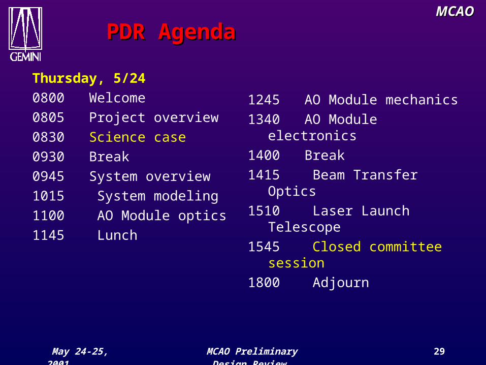
Thursday, 5/240800 Welcome 0805 Project overview 0830 Science case0930 Break0945 System overview1015 System modeling1100 AO Module optics1145 Lunch
1245 AO Module mechanics1340 AO Module electronics1400 Break1415 Beam Transfer Optics1510 Laser Launch
Telescope1545 Closed committee
session1800 Adjourn