ms/tp communications bus technical bulletincgproducts.johnsoncontrols.com/met_pdf/12011034.pdf ·...
TRANSCRIPT

MS/TP Communications Bus Technical BulletinCode No. LIT-12011034Software Release 9.0Issued January 2018
Refer to the QuickLIT website for the most up-to-date version of this document.
Document Introduction.............................................................................................................3Summary of Changes................................................................................................................3MS/TP Bus Overview.................................................................................................................3
FC Bus..................................................................................................................................................5SA Bus.................................................................................................................................................5Remote Field Bus................................................................................................................................6BACnet Router Configuration...............................................................................................................8Supervisory Engine Configuration for Adding Remote Field Bus.......................................................11BACnet Router Wiring.........................................................................................................................12Remote Field Bus Restrictions............................................................................................................13Remote Field Bus Status and Statistics Attributes..............................................................................14Remote Field Bus Status Commands.................................................................................................14End-of-Line Termination on the MS/TP Bus...................................................................................15Baud Rates on the MS/TP Bus.........................................................................................................16
Device Addressing on the MS/TP Bus...................................................................................17Setting a Device Address.................................................................................................................17Enabling Field Controllers for Wireless Operation........................................................................20
Local FC Bus Rules and Specifications................................................................................20End-of-Line Termination on Local FC Bus.....................................................................................24EOL Terminator Module....................................................................................................................25TEC26xx Series Thermostats and Third-Party MS/TP Devices....................................................26
SA Bus Rules and Specifications...........................................................................................27SA Bus Device Limits.......................................................................................................................28End-of-Line Termination on SA Bus................................................................................................30SA Buses with Multiple Network Sensors......................................................................................31
Remote Field Bus Rules and Specifications.........................................................................32EOL Termination on the Remote Field Bus....................................................................................34EOL Terminator Module for Remote Field Bus..............................................................................35
MS/TP Bus Cable Recommendations....................................................................................35Screw Terminal Blocks for Connecting FC and SA Bus Cables..................................................37Grounding the MS/TP Bus Cable Shield.........................................................................................38RJ-Style Modular Jack and Cables for SA Bus..............................................................................39
Commissioning Devices on the FC Bus................................................................................40Peer-to-Peer Communication.................................................................................................40Related Documentation...........................................................................................................40Appendix: FC Bus Auxiliary Devices.....................................................................................42
Repeaters...........................................................................................................................................42Configuring Repeaters........................................................................................................................43Fiber-Optic Modems.........................................................................................................................44Routing and Connecting the Fiber Cables..........................................................................................44Connecting Modems to MS/TP Bus....................................................................................................45Fiber Modem between Two Segments...............................................................................................45Setting Termination on Fiber Modems................................................................................................46Surge Protectors...............................................................................................................................48
1MS/TP Communications Bus Technical Bulletin

Appendix: Maximizing and Troubleshooting the MS/TP Bus..............................................51Maximizing Tips................................................................................................................................51MS/TP Bus Health Factors of the Diagnostics Tab........................................................................52Bus Health Index.................................................................................................................................53Bus Performance Index......................................................................................................................54Statistics Attributes..............................................................................................................................54Analyze Field Bus Command...........................................................................................................55Parameters That Affect MS/TP Communication............................................................................57Duplicate Addresses........................................................................................................................57Common Problems...........................................................................................................................58Correcting Physical Bus Problems.................................................................................................59Correcting Bus Overload Problems................................................................................................59Reading the Baud Rate of Devices..................................................................................................60Counting the COVs...........................................................................................................................61Disabling a Device on the Bus.........................................................................................................61Changing the Baud Rate of an Entire Bus......................................................................................62Automatic Low Resources Monitoring...........................................................................................62The Object Engine Input Queue.........................................................................................................63Available Free Memory.......................................................................................................................63Protocol Engine Input Queue..............................................................................................................63Protocol Engine Output Pending Queue.............................................................................................64
Appendix: Optimizing SA Bus Traffic....................................................................................65Excessive Traffic...............................................................................................................................65Inputs and COVs...............................................................................................................................65Outputs and Commands..................................................................................................................67SA Bus Traffic Reduction.................................................................................................................68
2Technical Bulletin

Document IntroductionThe BACnet® protocol MS/TP communications bus is a local network that connects supervisory controllers and fieldcontrollers to field point interfaces.
This document describes the specifications, device limits, and rules of the MS/TP communications bus, as well ashow to wire and terminate devices, and troubleshoot device communication on the MS/TP bus. The remote MS/TPfield bus is also described. With the addition of a BACnet IP to BACnet MS/TP Router, the Remote Field Bus allowsconnection to remote field controllers over IP.
This document is intended for the user who needs to know the rules, requirements, limits, specifications, andconfiguration of the MS/TP bus to design, wire, or troubleshoot an MS/TP application.
Summary of ChangesThe following information is new or revised:• Updated Table 3 to show addresses 1 to 3 as reserved for JCI use and 120-127 as reserved for multiple
coordinators when using applications with ZFR1810 coordinators.• Updated Table 6 to give more detail on NS series sensor limits.• Updated Related Documentation table.• Updated Appendix: FC Bus Auxiliary Devices to highlight need to use built-in termination when a fiber optic
modem is at the end of a network segment.• Updated Model 2110 modem throughout as Model 2110BAC, which is the BACnet version of the fiber optic
modem.• Added notes where appropriate about possibility of ordering a DIN rail mounting version, 2110BAC-DIN, if
available.• Updated and removed references to TEC3000 inTEC26xx Series Thermostats and Third-Party MS/TP Devices.• Updated Related Documentation table to include IOM2723, IOM3723, and IOM3733.
MS/TP Bus OverviewThe BACnet® protocol MS/TP communications bus is a local network that connects supervisory controllers and fieldcontrollers to field point interfaces. The bus is based on BACnet® standard protocol SSPC-135, Clause 9.
The BACnet MS/TP protocol is a peer-to-peer, multiple master protocol based on token passing. Only master devicescan receive the token, and only the device holding the token is allowed to originate a message on the bus. The tokenis passed from master device to master device using a small message. The token is passed in consecutive orderstarting with the lowest address. Subordinate devices on the bus only communicate on the bus when responding toa data request from a master device.
Important: Do not connect MS/TP devices and N2 devices to the same bus. MS/TP communications busesfollow different protocol and wiring rules from N2 communications buses, and MS/TP devices and N2devices are not compatible on the same bus.
An MS/TP bus is used for two types of buses: a Field Controller bus (FC) and a Sensor Actuator (SA) bus (Figure1). The MS/TP bus can also be extended remotely over the IP network with the addition of a BACnet IP to MS/TProuter.
The FC bus, SA bus, and Remote Field Bus are networks of daisy-chained devices. Each bus has only one bussupervisor, depending on which controllers are connected. On a local FC bus, the bus supervisor is the supervisoryengine. On the local SA bus, the bus supervisor is a field controller. On the Remote Field Bus, the bus supervisoris the BACnet IP to BACnet MS/TP Router (hereafter called the BACnet Router), which works with the supervisoryengine when a Remote Field Bus is installed.
3MS/TP Communications Bus Technical Bulletin

Note: When you install a BACnet Router for adding a Remote Field Bus to the job site, you need a site-level, uniqueMS/TP network number and device object ID (if it contains a device object) for the BACnet Router. In addition,it is critical that you determine if a BACnet Broadcast Management Device (BBMD) is required for the BACnetRouter. If you configure the BACnet Router as a BBMD, assign a static IP address to both the router and theNxM or ODS where you are configuring the MS/TP bus. For an existing installation, contact the BASManager,Building Manager, or IT department for information on available network numbers, device object IDs, andexisting BBMDs for crossing IP subnets. Information on configuring a BBMD in a BACnet Router (if it supportsthem internally) is available from the router vendor.
The bus supervisor communicates with devices on the supervised bus and with devices on the next (higher level)bus on the network. The bus supervisor typically starts the communication on the FC bus, remote FC bus, or SAbus. If an SA bus, FC bus, or Remote Field Bus does not have a bus supervisor, the master device with the lowestdevice address value on the bus and a specific baud rate selected starts the communication.
The ZFR1800 Series Wireless Field Bus System enables wireless communication on an MS/TP bus, allowing youto create wireless connections between Advanced Application Field Equipment Controllers (FACs), Field EquipmentControllers (FECs), or VAV Modular Assemblies (VMAs), Input/Output Modules (IOMs), and Network AutomationEngines (NAEs) or Network Control Engines (NCEs).
See Enabling Field Controllers for Wireless Operation and Related Documentation for detailed information aboutthe ZFR1800 Series Wireless Field Bus System.
Note: The ZFR1800 Series Wireless Field Bus System is not supported on the Remote Field Bus.
4MS/TP Communications Bus Technical Bulletin

FC BusAn FC bus connects a Metasys® system NAE or NCE to FACs, FECs, VMA16s, IOMs, and TEC26xx Seriesthermostats. Third-party BACnet MS/TP devices can also be connected to the FC bus.
Figure 1: Example of an MS/TP Communications Bus
On an FC bus, the NAE or NCE is the bus supervisor. An FC bus supports up to three bus segments that areconnected with network repeaters (Figure 9). See Local FC Bus Rules and Specifications for more information.
SA BusThe SA bus connects NCEs, FACs, FECs, and VMA16s (field controllers) to endpoint devices, such as IOMs, networkthermostats, network sensors, and Johnson Controls Variable Speed Drives (VSDs).
On an SA bus, an NCE, FAC, FEC, or VMA16 is the bus supervisor. The SA bus is a private MS/TP bus that onlysupports those devices that can be defined using the CCT programming tool. The bus does not support bus segments(Figure 13). See SA Bus Rules and Specifications for more information.
5MS/TP Communications Bus Technical Bulletin

Remote Field BusThe Remote Field Bus uses a BACnet Router to connect remote BACnet MS/TP devices such as FECs and VMA16sto the Metasys network. These devices include FACs, FECs, VMA16s, IOMs, TEC26xx Series thermostats, andother BACnet MS/TP field devices. Although several routers from different manufacturers are available, therecommended device is the LIP-ME201 BACnet Router from Loytec™ Electronics GmbH. Do not use anyUSB-powered MS/TP to IP converter, including the Johnson Controls® BACnet to MS/TP Router (TL-BRTRP-0).
Use a Remote Field Bus for applications where routing an RS-485 network directly to an NxE supervisory engineis not practical because of distance, cost, or poor accessibility. In many cases, an IP network connection is availableat both the NxE supervisory engine and at some point near the BACnet MS/TP devices. By leveraging the MetasysRemote Field Bus capability with installing the BACnet Router near the BACnet MS/TP devices, you can reducesystem cost. Also, when you choose MS/TP device integration with a router rather than BACnet Integration, accessto proprietary attributes, message types, and objects from Metasys field controllers is available. This functionalityprovides you with more information and more capability than the standard BACnet attributes, services, and objecttypes. For example, at the Site Management Portal you can view proprietary attributes such as communicationstatistics from mapped FEC Family devices. Also, remote MS/TP device integration supports the CCT Passthroughoption for downloading devices directly connected to the Remote Field Bus (but not to devices connected to thesensor bus).
Figure 2 shows an example of a Metasys network with a Remote Field Bus.
Figure 2: Example of a Remote Field Bus
6MS/TP Communications Bus Technical Bulletin

The Remote Field Bus is defined at a Metasys NxE supervisory engine or Open Data Server (ODS) Workstation(Figure 3) through field bus integration, similar to how a local MS/TP field bus is added. The Remote Field Busappears on the All Items Navigation tree in the Site Management Portal UI. You can also provide a custom nameto clearly identify the type of integration.
Note: To ensure acceptable system performance, make sure that you map all devices and objects that originatefrom a Remote Field Bus to a single supervisory engine, for example, if you have two NAEs (NAE-1 andNAE-2), each with a separate Remote Field Bus. Device 1 is defined under NAE-1, and Device 2 is definedunder NAE-2. In this arrangement, make sure you do not map Device 1 to NAE-2 or map Device 2 to NAE-1.If you mix remote field device mapping between supervisory engines, the Metasys system may start veryslowly, and devices may have difficulty staying online.
Figure 3: Example of a Remote Field Bus with ODS
Applications for the Remote Field Bus include:
• Any intra-building, inter-building, or remote location that has IP network connections readily available• Locations where it is cost prohibitive or difficult to run MS/TP wiring between devices and the NxEs, due to
distance, cost, accessibility, or customer factors• Locations where field controllers are segregated from the NxEs• Intra-building applications that connect segregated locations within a building (for example, connecting penthouses
to mechanical rooms)
7MS/TP Communications Bus Technical Bulletin

• Remote buildings where an MS/TP bus is not already available, but an Ethernet BACnet/IP network is (forexample, university or hospital campuses)
• Sites with a reliable network between buildings that do not need to have a separate NAE for the building (forexample, school districts)
Note: The ZFR1800 Series Wireless Field Bus System is not supported on the Remote Field Bus.
For details on how to add a Remote Field bus, refer to the MS/TP Field Bus Integration Object section in MetasysSMP Help (LIT-1201793). For details on how to add a Remote Field Bus to a Metasys supervisory engine with anODS, refer to the ODS Commissioning Guide (LIT-12011944).
Additional background on the Remote Field Bus is covered in the following sections:
• BACnet Router Configuration• Supervisory Engine Configuration for Adding Remote Field Bus• BACnet Router Wiring• Remote Field Bus Restrictions• Remote Field Bus Status and Statistics Attributes• Remote Field Bus Status Commands
BACnet Router ConfigurationConfiguration of the BACnet Router varies by vendor and model of the device, but several important configurationsettings are required for all routers. Table 1 lists those settings and Figure 4 provides an example. For more detailson BACnet Router parameters, refer to the documentation provided with your router.
Note: When you install a BACnet Router for adding a Remote Field Bus to the job site, you need a site-level, uniqueMS/TP network number and device object ID (if it contains a device object) for the BACnet Router. In addition,it is critical that you determine if a BACnet Broadcast Management Device (BBMD) is required for the BACnetRouter. If you configure the BACnet Router as a BBMD, assign a static IP address to both the router and theNxE or ODSwhere you are configuring the MS/TP bus. For an existing installation, contact the BASManager,Building Manager, or IT department for information on available network numbers, device object IDs, andexisting BBMDs for crossing IP subnets. Information on configuring a BBMD in a BACnet Router (if it supportsthem internally) is available from the router vendor.
8MS/TP Communications Bus Technical Bulletin

Table 1: BACnet Router AttributesUser Action or RecommendedSetting
DescriptionBACnet Router Attribute Name
Specify the network number assigned forBACnet/IP connections to the BACnetnetwork. Do not use 2000 or 65000 asthe network number; these numbers areused for existing embedded networks.
Note: In most cases, the IP side of theBACnet Router shares the sameNetwork Number as all of theBACnet IP connections in oneBACnet network (example: 1001).Figure 4 shows an example.
A unique identifier defined for the BACnetIP network connection on the BACnetRouter. The supervisory engine uses thisnumber to locate the device.
Network Number (for EthernetBACnet/IP)
Specify the network number for theBACnet Router on the MS/TP side withthe network address specified in theMetasys supervisory engine under whichthe Remote Field Bus is defined. TheMS/TP side of each BACnet Routermusthave a unique Network Number for thesite because each remote bus is aseparate network (example: 2801, 2802,2803). Do not use the same networknumber as any of the NAE MS/TP trunks.Figure 4 shows an example.
A unique identifier defined for the BACnetMS/TP network connection on the BACnetRouter.
Network Number (for BACnet MS/TP,Port 1)
Specify a unique number.
Note: As you add routers, be sure toreplace the router's default deviceID with a unique value for yoursite. The router's device ID mustbe different from the device ID ofall other BACnet devices at thesite.
The Device ID is the instance number forthe BACnet Router. This number must beunique across the building networks for alldevice instances.
Device ID
Specify a unique name.A name to identify the BACnet Router.This name must be unique across thebuilding network.
Device Name
Enable and configure the router BBMDswith an appropriate broadcast distributiontable.
The IP network subnets used by both theBACnet Router and the supervisory enginenormally require that you define BBMDson each subnet if those IP subnets aredifferent. Each IP subnet generallyrequires exactly one defined BBMD.Manyrouters include BBMD capability in orderto simplify this requirement.
BACnet/IP Broadcast ManagementDevice (BBMD)
9MS/TP Communications Bus Technical Bulletin
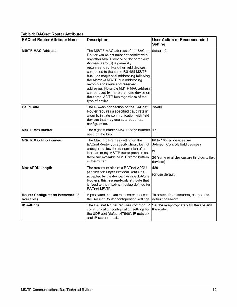
Table 1: BACnet Router AttributesUser Action or RecommendedSetting
DescriptionBACnet Router Attribute Name
default=0The MS/TP MAC address of the BACnetRouter you select must not conflict withany other MS/TP device on the same wire.Address zero (0) is generallyrecommended. For other field devicesconnected to the same RS-485 MS/TPbus, use sequential addressing followingthe Metasys MS/TP bus addressingrecommendations and reservedaddresses. No singleMS/TPMACaddresscan be used by more than one device onthe same MS/TP bus regardless of thetype of device.
MS/TP MAC Address
38400The RS-485 connection on the BACnetRouter requires a specified baud rate inorder to initiate communication with fielddevices that may use auto-baud rateconfiguration.
Baud Rate
127The highest master MS/TP node numberused on the bus.
MS/TP Max Master
80 to 100 (all devices areJohnson Controls field devices)
or
20 (some or all devices are third-party fielddevices)
The Max Info Frames setting on theBACnet Router you specify should be highenough to allow the transmission of atleast as many MS/TP frame packets asthere are available MS/TP frame buffersin the router.
MS/TP Max Info Frames
480
(or use default)
The maximum size of a BACnet APDU(Application Layer Protocol Data Unit)accepted by the device. For most BACnetRouters, this is a read-only attribute thatis fixed to the maximum value defined forBACnet MS/TP.
Max APDU Length
To protect from intruders, change thedefault password.
A password that you must enter to accessthe BACnet Router configuration settings.
Router Configuration Password (ifavailable)
Set these appropriately for the site andthe router.
The BACnet Router requires common IPcommunication configuration settings forthe UDP port (default 47808), IP network,and IP subnet mask.
IP settings
10MS/TP Communications Bus Technical Bulletin

Figure 4: Setting Network Address or Network Number
Supervisory Engine Configuration for Adding Remote Field BusYou define the Remote Field Bus at a Metasys supervisory engine much like you define a local field bus. Importantsettings include Trunk Number and Network Address.
11MS/TP Communications Bus Technical Bulletin
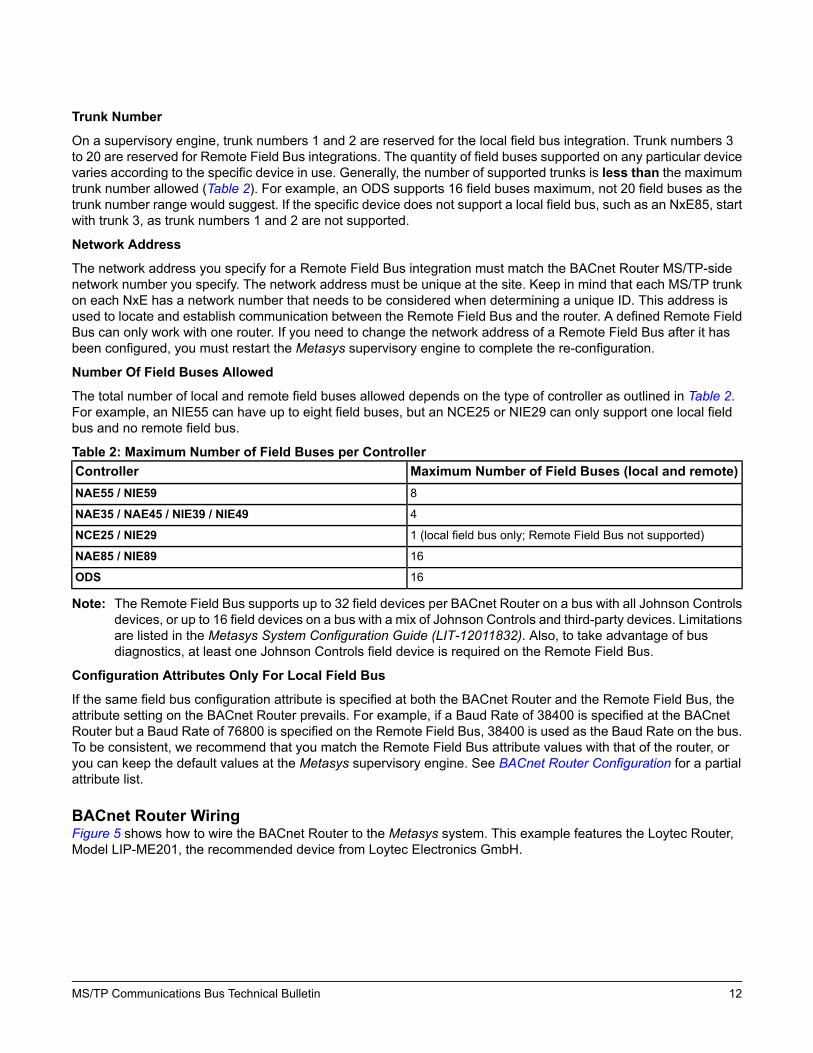
Trunk Number
On a supervisory engine, trunk numbers 1 and 2 are reserved for the local field bus integration. Trunk numbers 3to 20 are reserved for Remote Field Bus integrations. The quantity of field buses supported on any particular devicevaries according to the specific device in use. Generally, the number of supported trunks is less than the maximumtrunk number allowed (Table 2). For example, an ODS supports 16 field buses maximum, not 20 field buses as thetrunk number range would suggest. If the specific device does not support a local field bus, such as an NxE85, startwith trunk 3, as trunk numbers 1 and 2 are not supported.
Network Address
The network address you specify for a Remote Field Bus integration must match the BACnet Router MS/TP-sidenetwork number you specify. The network address must be unique at the site. Keep in mind that each MS/TP trunkon each NxE has a network number that needs to be considered when determining a unique ID. This address isused to locate and establish communication between the Remote Field Bus and the router. A defined Remote FieldBus can only work with one router. If you need to change the network address of a Remote Field Bus after it hasbeen configured, you must restart the Metasys supervisory engine to complete the re-configuration.
Number Of Field Buses Allowed
The total number of local and remote field buses allowed depends on the type of controller as outlined in Table 2.For example, an NIE55 can have up to eight field buses, but an NCE25 or NIE29 can only support one local fieldbus and no remote field bus.
Table 2: Maximum Number of Field Buses per ControllerMaximum Number of Field Buses (local and remote)Controller8NAE55 / NIE59
4NAE35 / NAE45 / NIE39 / NIE49
1 (local field bus only; Remote Field Bus not supported)NCE25 / NIE29
16NAE85 / NIE89
16ODS
Note: The Remote Field Bus supports up to 32 field devices per BACnet Router on a bus with all Johnson Controlsdevices, or up to 16 field devices on a bus with a mix of Johnson Controls and third-party devices. Limitationsare listed in the Metasys System Configuration Guide (LIT-12011832). Also, to take advantage of busdiagnostics, at least one Johnson Controls field device is required on the Remote Field Bus.
Configuration Attributes Only For Local Field Bus
If the same field bus configuration attribute is specified at both the BACnet Router and the Remote Field Bus, theattribute setting on the BACnet Router prevails. For example, if a Baud Rate of 38400 is specified at the BACnetRouter but a Baud Rate of 76800 is specified on the Remote Field Bus, 38400 is used as the Baud Rate on the bus.To be consistent, we recommend that you match the Remote Field Bus attribute values with that of the router, oryou can keep the default values at the Metasys supervisory engine. See BACnet Router Configuration for a partialattribute list.
BACnet Router WiringFigure 5 shows how to wire the BACnet Router to the Metasys system. This example features the Loytec Router,Model LIP-ME201, the recommended device from Loytec Electronics GmbH.
12MS/TP Communications Bus Technical Bulletin

Figure 5: Wiring BACnet Router
Remote Field Bus RestrictionsCompared to the local MS/TP field bus, the Remote Field Bus has several operational restrictions.
Number of Field Controllers on a Remote Field Bus
The number of controllers that can successfully operate on a Remote Field Bus is generally less than that of a localfield bus, and is heavily dependent on the capabilities of the router used. Generally, a good quality router can supportat least 10 BACnet MS/TP devices, and some can support more (see Table 9). If you notice that devices go offlinerandomly, or you notice a large number of BACnet message retries, you may have exceeded the maximum numberof supported devices for the router. You may be able to use a larger number of devices if you mitigate the messagetraffic that originates from field devices located on the Remote Field Bus.
Maximum Change of Values (COVs)
The total number of COVs per supervisory engine must remain at less than 500 per minute. To determine and tunethe number of COVs per minute on a Remote Field Bus, use the FDD tool, but only if you have at least oneJohnson Controls field controller on the bus. The FDD tool helps you find chatty devices and helps decrease theCOV rate by updating the COV increments.
13MS/TP Communications Bus Technical Bulletin

Field Controller Main Code Release
For Remote Field Bus compatibility, the Main Code for the field controllers you connect to remotely must be atMetasys system Release 5.3 or later. Remote field bus communication is not as robust with controllers that arerunning older releases of the Metasys system.
CCT Passthrough Loading
Generally, you can upload and download code and applications with CCT Passthrough for devices directly connectedto a Remote Field Bus (subject to router message load levels). However, you cannot use CCT Passthrough todownload code to an IOM connected to the SA bus of a field controller. In these situations, use a WirelessCommissioning Controller at the remote location.
Device and Point Mapping
When you define a Remote Field Bus, be sure to map all devices and points at the remote controllers through thesame Remote Field Bus. For most networks, a detrimental increase in router traffic occurs if multiple integrationsuse the same router and network number. This is true regardless of where the multiple integrations are defined orif a BACnet Integration is used.
Remote Field Bus Status and Statistics AttributesWith the local field bus, the status and statistics values are obtained directly from the MS/TP communication software,which has direct access to the MS/TP communication frames. However, with the Remote Field Bus, the status andstatistics values must be obtained from one of the remote FEC Family BACnet controllers communicating throughthe BACnet Router. When at least one Metasys MS/TP field controller is mapped to the Remote Field Bus as anFEC Family BACnet device, the system can retrieve and display the status and statistics values from the RemoteField Bus. Be aware that if this field controller goes offline and a different FEC Family field controller is selected toprovide remote bus statistics, the values obtained may abruptly change because the values are from a differentcontroller. This is normal operation.
The following Metasys attributes are located under the Diagnostics tab of a Remote Field Bus.
Logging Object Reference
This attribute indicates the remote Metasys MS/TP field controller configured for obtaining MS/TP trunk status andstatistics values. The device name appears if available; otherwise, the MAC address on the MS/TP trunk appears.The value is empty for a local field bus, or if no Metasys field controller is available or known. The remote Metasysdevice is chosen by first looking for an online, mapped FEC Family BACnet device. If none is found, then the AnalyzeField Bus command results (if any) are scanned for a possible FEC family device.
Bus Health Index and Bus Performance Index
Trunk health and performance moving average calculations are generally delayed one update time (usually oneminute) on a Remote Field Bus due to the delays in reading raw statistics values remotely. As mentioned previously,the numbers reported experience a transient glitch if you change theMetasys BACnet device used to gather statistics.
Port Status
The value of this attribute is Remote Trunk for a Remote Field Bus. For an online local field bus, the value of thisattribute is Active.
Remote Field Bus Status CommandsThe Site Management Portal UI offers a few commands that relate to Remote Field Bus operation.
Latch Statistics
The Latch Statistics command is redirected to the FEC Family BACnet Device used for collecting MS/TP trunkstatistics.
14MS/TP Communications Bus Technical Bulletin

Clear Statistics
The Clear Statistics command is redirected to the FEC Family BACnet Device used for collecting MS/TP trunkstatistics. If the device used for collecting statistics changes after this command is issued, the new device is notcleared unless the command is issued again.
Sync Field Device Time(s)
The Sync Field Device Time(s) command sends a high-priority time synchronization command to all child BACnetIntegration devices, based on each device mapper object's Manual Time Sync Type attribute.
If the Manual Time Sync Type is set to:
• UTC: UTC time synchronization message is sent.• Local: A local time synchronization message is sent.• None: No message is sent.• Auto: The mapper object's Protocol Services Supported attribute is used to determine which type of time sync
is supported, and if:
- utcTimeSynchronization is set, the code functions as if Time Sync Type is set to UTC.- utcTimeSynchronization is not set and timeSynchronization is set, local time is set.- neither utcTimeSynchronization nor timeSynchronization is set, an error is returned.
Analyze Field Bus
The Analyze Field Bus option has been modified on a Remote Field Bus to use BACnet services that can passthrough routers. (The local field bus operation can use MS/TP test messages, which do not pass through routers.)In addition, the bus can only detect remote devices that answer the wild card device instance value of 4194303.Some commonly used MS/TP devices do not respond to the wild card device instance value and are not detectedby this operation. Devices already mapped are always displayed.
Note: Running a bus analysis remotely requires significantly more time to complete than what a local field busrequires, and adds significant message loading to the router while running.
End-of-Line Termination on the MS/TP BusDaisy-chained RS485-protocol networks typically require some type of end-of-line (EOL) termination to reduceinterference caused by signal reflection that occurs when data transmissions reach the end of a bus segment andbounce back on the segment. The high baud rates on MS/TP bus applications require robust EOL termination andstrict adherence to the EOL termination rules. Figure 6 shows an example of the EOL termination settings on anMS/TP bus application.
The EOL termination requirements for the FC bus are different from the SA bus requirements. See End-of-LineTermination on Local FC Bus and End-of-Line Termination on SA Bus for more information.
Also, third-party MS/TP devices and TEC26xx Series thermostats have different EOL termination requirements fromMetasys devices on the FC bus. See TEC26xx Series Thermostats and Third-Party MS/TP Devices for moreinformation.
15MS/TP Communications Bus Technical Bulletin

Figure 6: EOL Terminations on an MS/TP Bus
Baud Rates on the MS/TP BusAn MS/TP bus can be configured to communicate at one of four different baud rates. All of the devices on an MS/TPbus must communicate at the same baud rate.
The baud rate setting determines the rate at which devices communicate data over the bus. The baud rate settingsavailable onMetasysMS/TP devices are 9600 bps, 19.2 kbps, 38.4 kbps, 76.8 kbps, and Auto. The baud rate settingfor Metasys devices is set in the Metasys software.
Note: The BACnet Standard only requires support for 9600 baud. Some third-party vendor devices might not supportall the baud rates supported by theMetasys system. Reducing the baud rate to accommodate these devicesaffects overall performance.
We recommend setting all MS/TP bus supervisors (NAEs, NCEs, and BACnet Routers) to 38,400.
We recommend setting all field controllers on the FC bus or Remote Field Bus (FACs, FECs, VMA16s, and IOMs)to Auto. In the Auto setting, theMetasys devices listen for the bus supervisor to communicate first; the devices thenautomatically set their baud rate to the bus supervisor’s baud rate. FACs, FECs, VMA16s, and IOMs ship with adefault baud rate setting of Auto.
If you anticipate critical peer-to-peer communication and therefore do not want field controllers to wait for the bussupervisor to establish the baud rate, you can specify the baud rate for each device immediately at startup. Choosethe baud rate carefully if you use this method, since changing it requires changing each device separately.
Typically, the baud rate setting on bus repeaters and third-party MS/TP devices is configured manually at the device,and the baud rate setting must match the bus supervisor’s baud rate. A third-party device that does not supportauto-baud establishes the baud rate for the MS/TP network if the NxE is not connected. Refer to the manufacturer’sproduct documentation for information on setting the device’s baud rate.
16MS/TP Communications Bus Technical Bulletin

The Metasys software contains the following two device attributes that relate to the baud rate:
• Baud Rate Selection allows you to set the baud rate for the device using the System Configuration Tool (SCT)for NAEs, or the Controller Configuration Tool (CCT) for FACs, FECs, VMA16s, and IOMs.
• Active Baud Rate allows you to view the baud rate at which the device is communicating on the active bus whenAuto baud is selected for the device.
For more information on Metasys system attributes, refer to the Metasys system Help (LIT-1201793).
The high baud rates capable on MS/TP buses limit the range of wire gauges used on the bus. The baud rate, wiregauge, wire length, and the number of devices are related. Higher baud rates support more devices but require smallgauge wire that provides lower capacitance. A lower baud rate may be required to use existing, larger gauge wirethat has higher capacitance, but may support fewer devices. We recommend 38,400 baud using 22 AWG strandedwire. This combination provides the best balance between performance and installation sensitivity.
For information on determining wire gauges, wire lengths, and the number of devices supported, see MS/TP BusCable Recommendations.
Device Addressing on the MS/TP BusEach device connection on an MS/TP bus requires a device address to coordinate communication. Each bus hasa set of device addresses that is separate and independent from the device addresses on all other buses. Devicesconnected to both an MS/TP bus and SA bus have two device addresses, one for each bus connection (Figure 7).
In theMS/TP bus hierarchy, device connections on separate buses can have the same device address. For example,every bus supervisor connection on an MS/TP bus has a device address of 0 (zero), and the device address for thefirst network sensor on any SA bus is 199. This is possible because separate buses are identified with differentnetwork numbers. Figure 7 shows a simple example of an MS/TP bus and the device addresses for connections onthe FC bus and SA bus.
An NAE, NCE, or BACnet Router is the bus supervisor on an FC bus (or Remote Field Bus). The FAC, FEC, VMA16,or the field controller on an NCE is the bus supervisor on an SA bus. Bus supervisors have a fixed device addressof 0 (zero) that cannot be changed (Figure 7). Depending on the model, a network sensor has a fixed address of199 or an assigned (switch-selectable) address between 200 and 203. Table 3 provides a list of the valid MS/TPdevice address values and address value ranges for MS/TP devices.
EachMS/TPmaster controller passes the token to the controller with the next known address. After 50 token passes,each controller searches for other controllers that might have joined the network by attempting to send the token tothe controller with the next consecutive address, starting with one higher than its own, until one is found. While youdo not need to address devices on the trunk consecutively, you can improve performance by minimizing addressskipping. To help with address value selection, see Table 3.
Note: The devices on the bus do not need to be physically wired in sequential order.
Setting a Device AddressFor most devices on an MS/TP bus, the (non-supervisory) device address is set by positioning the DIP switches onthe device’s ADDRESS DIP switch block. The DIP switch blocks are binary switch blocks, with each switchrepresenting a binary numerical value when the switch is in the ON position.
The device address set on the ADDRESS DIP switch block applies to the device connection on the bus where thedevice is not the bus supervisor. For example, the DIP switches on FACs, FECs, or VMA16s (master devices) setthe device address for the device connection to the FC bus (or Remote Field Bus). If the FAC, FEC, or VMA16 alsosupervise an SA bus, the FAC's, FEC's, or VMA16's address on an SA bus is 0 by default (Figure 7).
An IOM has only one device connection, which can connect to either an FC bus or an SA bus (but not both); therefore,the device address set on an IOM applies to the bus to which the IOM is connected. (An IOM is never a bussupervisor.)
17MS/TP Communications Bus Technical Bulletin

Figure 7: MS/TP Bus Showing FC Bus and SA Bus Addresses
18MS/TP Communications Bus Technical Bulletin

Table 3: Valid MS/TP Bus Address Values and Address Ranges for MS/TP Bus DevicesDevicesClassAddress Value/
Address RangeFC Bus: NAE or NCE
SA Bus: FAC, FEC, VMA16, or NCE
Remote Field Bus: BACnet Router
Bus Supervisor0
Reserved for JCI use1–3
ZFR1810 Wireless Field Bus Coordinator
Note: On applications using ZFR1810 coordinators, addressvalues 120 to 127 are reserved for multiple coordinators.
Reserved120-127
FC Bus: FACs, FECs, VMA16s, IOMs, TECs, and non-FX familydevices
Remote Field Bus: FACs, FECs, VMA16s, IOMs, TECs, andnon-CH family devices
SA Bus: IOMsNote: On applications using an NCE, the address value 4 is
reserved for the NCE’s integral field controller. Onapplications using ZFR1810 coordinators, addressvalues 120 to 127 are reserved for multiple coordinators.
Master Range4–127
FACs/FECs/IOMs/VMAs: Wireless mode with address rangeof 4-127 and bit 128 active
Reserved4–119 (Switch 128 ON)
Subordinate devices, VSDs, and NS network sensors on theSA Bus. Not Supported on the FC bus.
Subordinate Range128–254
VAV Balancing Sensor (handheld)Reserved198
Most NS Series Network Sensor models or VAV BalancingSensor (wall-mounted)
Reserved199
NS Series Network Sensors (specified models)Reserved200–203
NS-DTN7043-0 and NS-DTN7083-0 Network SensorsReserved204–211
NS-BCN7004-0 Network CO2 SensorReserved212–219
Do not apply address 255 to any device.Broadcast255
Important: On FAC, FEC, VMA16, and IOM Series controllers only, the 128 DIP switch on the controller’s deviceaddress DIP switch block is a mode switch used to enable the controller to operate in a wireless modeusing the ZFR1800 Series Wireless Field Bus System. On any FAC, FEC, VMA16, or IOM Seriescontroller that is hardwired to anMS/TPBus, set the 128 DIP switch to the OFF position.Operatingany FAC, FEC, VMA16, or IOM that is hardwired to an MS/TP Bus with the controller’s 128 DIP switchset to the ON position results in communication failure on the bus.
As you set the device address, the best practice is to set the highest switch value first, then the next highest switchvalue, and so on, until the total of the switch values equal the intended device address. For example, positioningswitches 16, 4, and 1 to ON sets the device address to 21 for a device on the FC bus.
19MS/TP Communications Bus Technical Bulletin

Figure 8: Setting the Device Address and Wireless Operation Mode on the ADDRESS DIP Switch Block
Notes:
• You must set switch 128 to OFF on all Metasys controllers that are hardwired to an FC bus. Set switch 128 toON only on FACs, FECs, VMA16s, and IOMs that operate on a Metasys ZFR1800 Series Wireless Field Bus.
• Devices may go offline momentarily when a device address is changed on an active bus. A device reset is notrequired on field controllers or supervisory engines after changing the MS/TP address.
Some devices, such as the TEC26xx Series thermostats and third-party MS/TP devices, use their own configurationsettings to establish the device address for their connection to the bus. Refer to the device manufacturer’s productdocumentation for instructions on setting the device address. The device address values for TEC thermostats andall third-party devices must comply with the rules and ranges described previously.
Enabling Field Controllers for Wireless OperationThe ZFR1800 Series Wireless Field Bus System enables wireless communication, allowing you to create wirelessconnections between NAEs or NCEs and FACs, FECs, or VMA16s.
Note: The ZFR1800 Series Wireless Field Bus System is not supported on the Remote Field Bus.
On FAC, FEC, and VMA16 controllers, you can enable the controller to operate with a ZFR1800 Series wirelesssystem and connect an MS/TP Bus in a wireless mode by setting the 128 DIP switch on the device address DIPswitch block to ON. See Figure 8.
To operate with a ZFR1800 Series field bus, an FAC, FEC, or VMA16 must be connected to a ZFR1811 or ZFR1812Wireless Field Bus Router, and the associated NAE or NCE must be connected to a ZFR1810 Wireless Field BusCoordinator. See Related Documentation for references to more information about the ZFR1800 Series WirelessField Bus System, FACs, FECs, VMA16s, NCEs, and NAEs.
Local FC Bus Rules and SpecificationsTable 4, Table 5, and Figure 9 provide rules and specifications for the local FC bus. (For the Remote Field Bus, seeTable 9.)MetasysMS/TP devices generate less data traffic than third-party MS/TP devices and TEC26xx thermostats.Connecting third-party devices or TEC26xx thermostats to the FC bus increases data traffic, reduces bus performance,and reduces the number of devices that can be connected to the FC bus.
20MS/TP Communications Bus Technical Bulletin

Table 4: Local FC Bus Rules and LimitationsRules/LimitsCategoryNAE55 Series models can support up to two local FC buses.
Note: When a second FC bus is added to the NAE, be sure the trunk number has not beenused on the NAE and enter a Network Address that is unique for the entire site. Thisapplies for any model of NAE.
NAE45 Series models can support one local FC bus.
NAE35 Series models can support one local FC bus (but an NAE35 FC bus supports onlyhalf the number of devices that are supported on an FC bus on an NAE45 or NAE55).
NCE25 Series models can support one local FC bus. NCEs must be ordered specifically asN2 or MS/TP models.
Note: An FC port on an NAE/NCE can connect to only one bus segment on an FC bus.Only a daisy-chain topology is allowed (no T or Star topology configurations).Refer to the Network Engines Product Bulletin (LIT-12012138) and the NetworkController Engine Product Bulletin (LIT-12011283) for complete information onMS/TPbus support on NAE and NCE models.
General
NCE25 models support 32 MS/TP devices (maximum) on an FC bus trunk and up to 3 bussegments.
NAE35 models support the following device limits on an FC bus trunk:
When all of the devices connected on the FC bus are Metasys FACs, FECs, VMA16s,TEC36xxs, and/or IOMs, the device and bus segment limits are as follows:
• 50 devices total per FC bus (maximum)• 3 bus segments per FC bus (maximum)
When one or more non-FEC family device is connected on the FC bus, the device and bussegment limits are as follows:• 32 devices total per FC bus (maximum)• 3 bus segments per FC bus (maximum)
NAE45 and NAE55 models support the following device limits on an FC bus trunk:
When all of the devices connected on the FC bus are Metasys FACs, FECs, VMA16s,TEC36xxs, and/or IOMs, the device and bus segment limits are as follows:
• 100 devices total per FC bus (maximum)• 3 bus segments per FC bus (maximum)• 50 devices per bus segment (maximum, not to exceed 100 devices per FC bus)
When one or more non-FEC family device is connected on the FC bus, the device and bussegment limits are as follows:• 64 devices total per FC bus (maximum)• 3 bus segments per FC bus (maximum)• 32 devices per bus segment (maximum, not to exceed 64 devices per FC bus)
Number of Devices and BusSegments
Bus segments on an FC bus are connected with repeaters (only). Up to two cascadedrepeaters may be applied to an FC bus (to connect three bus segments).
21MS/TP Communications Bus Technical Bulletin
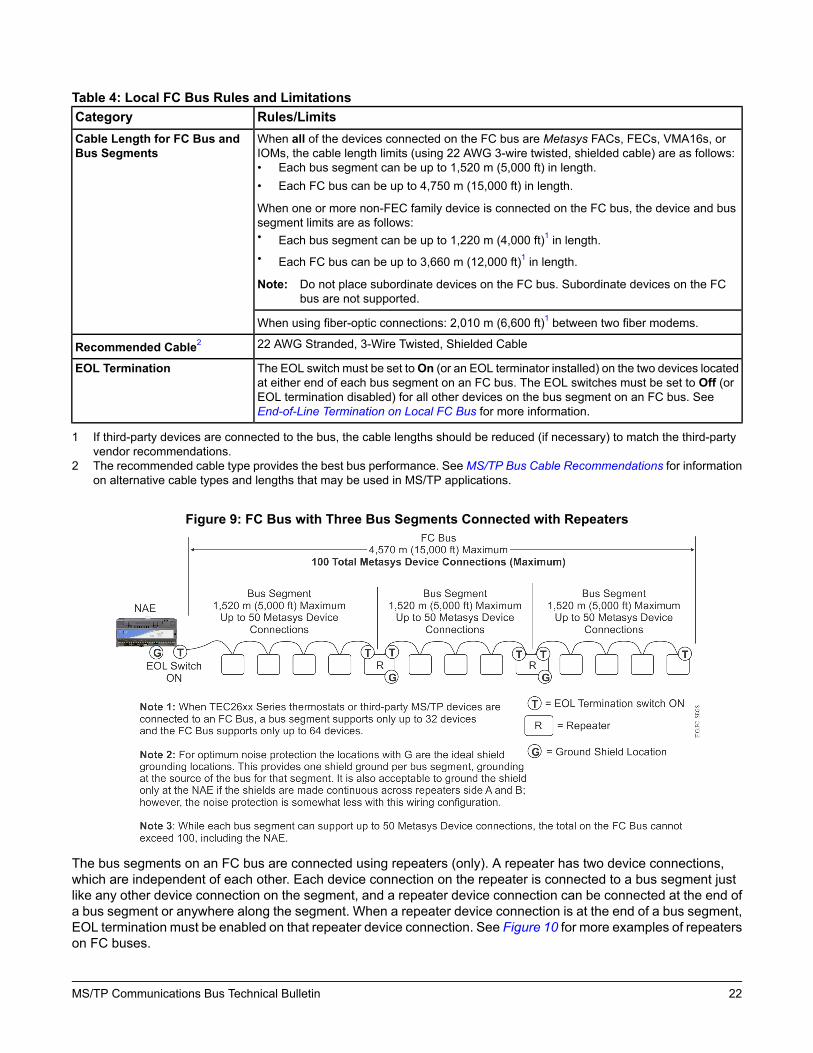
Table 4: Local FC Bus Rules and LimitationsRules/LimitsCategoryWhen all of the devices connected on the FC bus are Metasys FACs, FECs, VMA16s, orIOMs, the cable length limits (using 22 AWG 3-wire twisted, shielded cable) are as follows:• Each bus segment can be up to 1,520 m (5,000 ft) in length.• Each FC bus can be up to 4,750 m (15,000 ft) in length.
When one or more non-FEC family device is connected on the FC bus, the device and bussegment limits are as follows:• Each bus segment can be up to 1,220 m (4,000 ft)1 in length.• Each FC bus can be up to 3,660 m (12,000 ft)1 in length.
Note: Do not place subordinate devices on the FC bus. Subordinate devices on the FCbus are not supported.
Cable Length for FC Bus andBus Segments
When using fiber-optic connections: 2,010 m (6,600 ft)1 between two fiber modems.
22 AWG Stranded, 3-Wire Twisted, Shielded CableRecommended Cable2
The EOL switch must be set toOn (or an EOL terminator installed) on the two devices locatedat either end of each bus segment on an FC bus. The EOL switches must be set to Off (orEOL termination disabled) for all other devices on the bus segment on an FC bus. SeeEnd-of-Line Termination on Local FC Bus for more information.
EOL Termination
1 If third-party devices are connected to the bus, the cable lengths should be reduced (if necessary) to match the third-partyvendor recommendations.
2 The recommended cable type provides the best bus performance. SeeMS/TP Bus Cable Recommendations for informationon alternative cable types and lengths that may be used in MS/TP applications.
Figure 9: FC Bus with Three Bus Segments Connected with Repeaters
The bus segments on an FC bus are connected using repeaters (only). A repeater has two device connections,which are independent of each other. Each device connection on the repeater is connected to a bus segment justlike any other device connection on the segment, and a repeater device connection can be connected at the end ofa bus segment or anywhere along the segment. When a repeater device connection is at the end of a bus segment,EOL termination must be enabled on that repeater device connection. See Figure 10 for more examples of repeaterson FC buses.
22MS/TP Communications Bus Technical Bulletin

Table 5: FC Bus SpecificationsSpecificationCategoryMessage Headers checked using 8-bit Cyclic Redundancy Check (CRC) test.Message data check using 16-bit CRC test.
Error Checking
0–255 (See Device Addressing on the MS/TP Bus for more information.)Device Addressing
RS485Data Transmission Standard
BACnet® MS/TPSignaling Method
9600; 19,200; 38,400; or 76,800 baud as selected by bus supervisor. (See BaudRates on the MS/TP Bus.)
Signaling Rate
Meets EN61000-4-4 and EN6100-4-5 requirements for heavy industrialapplications.
Protected against misapplication of 24 VAC.
Transient Immunity
Integral EOL Termination switch or add-on EOL Terminator module (SeeEnd-of-Line Termination on Local FC Bus.) Do not use third-party EOLtermination.
EOL Termination Method
Only one hard ground connection per bus segment when using shielded cable.(See Grounding the MS/TP Bus Cable Shield.)
Shield Grounding
Daisy-chainedPhysical Configuration
Repeaters• Acromag® 4683-TTM-1F (115 VAC)• Acromag 4683-TTM-2F (230 VAC)• Acromag 4683-TTM-3F (24 VAC)
Note: A repeater is required to support more than 50 devices per trunk segmentor trunk cable segment longer than 1,524m (5,000 ft). Only the repeaterslisted here provide EOL termination switching that is compatible withMS/TP.
Transient Eliminator
Advanced Protection Technologies Transient Eliminator TE/JC04C12
Fiber Modem• S.I. Tech Model 2110BAC Fiber-Optic Modem and S.I. Tech 2121 Power
Supply• 9-pin Male Connector Kit (required by 2110BAC modem)• Does not support 76,800 baud
Note: A DIN rail mounting version of the Model 2110BAC may be availableas Model 2110BAC-DIN. However it does not appear on the S.I. Techweb site at the time of this writing. Contact S.I. Tech using contactinformation on their web site at http://www.sitech-bitdriver.com/index.htm.
Optional Vendor Components
23MS/TP Communications Bus Technical Bulletin

End-of-Line Termination on Local FC BusThe FC bus requires EOL termination at the end of each bus segment. Figure 10 shows four examples of EOLtermination on the FC bus.
Figure 10: FC Bus Segment EOL Termination Scenarios
Note: • Set the EOL termination switch on a repeater’s device connection to ON only when the repeater connectionterminates a bus segment. See Scenarios 3 and 4 in Figure 10.
• Third-party MS/TP devices and TEC26xx Series thermostats have different EOL termination requirementson the FC bus. See TEC26xx Series Thermostats and Third-Party MS/TP Devices for more information.
24MS/TP Communications Bus Technical Bulletin

EOL Terminator ModuleTheMS-BACEOL-0 RS485 EOL Terminator is a non-smoke control listed component that provides EOL terminationon FC bus segments when the device connected at the end of a bus segment does not have integral EOL terminationcapability.
The EOL terminator is a compact, lightweight, module wrapped in a protective cover, as shown in the followingfigure, that can be quickly installed in a variety of ways. The EOL connects directly to the terminating device on abus segment with the attached wire leads. The EOL requires 24 VAC, Class 2 power supplied by the field device orother 24 VAC source.
Figure 11: MS-BACEOL-0 RS485 EOL Terminator
An EOL terminator is required in all Metasys MS/TP applications wherever a terminating device on an FC bussegment does not have integral EOL termination (for example, TEC26xx Series thermostats). Some thermostats,such as the TEC3000 Series, have built-in EOL termination switches.
The EOL terminator is designed for FC buses and provides better bus performance than the integral EOL terminationon third-party devices. An EOL is recommended wherever a third-party device terminates an FC bus segment. Ifthe EOL terminator is connected to a third-party device that has integral EOL termination, the integral EOL terminationon the third-party device must be disabled.
25MS/TP Communications Bus Technical Bulletin

Figure 12: MS-BACEOL-0 RS485 End-of-Line Terminator Dimensions
TEC26xx Series Thermostats and Third-Party MS/TP DevicesTEC26xx Series thermostats and third-party MS/TP devices generate more data traffic thanMetasysMS/TP devices.Increased data traffic reduces FC bus performance and reduces the number of devices that can be connected tothe bus. When any of these devices are connected on an FC bus, different device and cable length limits apply tothe bus and bus segments.
If you connect one or more TEC26xx Series thermostats and third-party BACnet MS/TP devices on an FC bus, thesupported maximum device counts, bus segments, and bus length are as follows:
• 64 devices total per FC bus (maximum)• 3 bus segments per FC bus (maximum)• 32 devices per bus segment (maximum, not to exceed 64 devices total on FC bus)• 1,220 m (4,000 ft) maximum per bus segment (using 22 AWG stranded, 3-wire twisted, shielded cable)• 3,660 m (12,000 ft) maximum per FC bus (using 22 AWG stranded, 3-wire twisted, shielded cable)
Third-party MS/TP devices also have different EOL termination requirements.
26MS/TP Communications Bus Technical Bulletin

SA Bus Rules and SpecificationsThe SA bus connects IOMs, VSDs, and NS-Series network sensors to field controllers. Figure 13 shows three SAbus examples. Table 6 and Table 7 provide SA bus rules and specifications.
Table 6: SA Bus RulesRules/LimitsCategoryEach bus supervisor supports one SA Bus (and each SA Bus is a single segment).General
An SA Bus supports up to 10 devices. The SA bus supervisor providespower for all subordinate devices connected to the SA bus, including upto four NS network sensors. IOMs connected to the SA bus are not poweredby the bus supervisor.
Note: Exceeding the SA bus power limit can result in devices going offline andpoor bus performance. See SA Bus Device Limits for more informationon SA bus power limits.The recommendation of placing no more than 4 NS Series devices ona given SA Bus is primarily limited due to COV transmit rateconsiderations. If the COV transmit rate of a combined bus is maintainedbelow 500/minute, it may be possible to place more than 4 NS Seriesdevices on a given bus. If more than 4 NS Series devices are placed ona combined bus and SA Bus performance degrades, it is likely due tothe amount of existing bus traffic and a different application may berequired. Three factors must be considered when determining howmanyNS network sensors you can add:
1) Available device addresses —• The limit for standard NS Series wall mounted sensors is 5. Using
4 addressable models and a single static address (199) model, 5devices can fit on a single SA Bus. Flush mount (NS-FTN7003-x)sensors use the same address range.
• The limit for NS Series DA-T (NS-DTN70x3-0) sensors on the busis 8. The number of available dip switch addresses is from 204 to211.
• The limit for NS Series CO2 (NS-BCN7004-x) sensors on the bus is8. The number of available dip switch addresses is 212 to 219.
2) Power consumption — The amount of power available is determinedby which models are chosen for the application. See SA Bus DeviceLimits.
3) Trunk traffic — anything over 500 COV transmits per minute isconsidered excessive.
Number of Devices Supported on the SABus
SA Buses do not support repeaters.
365 m (1,200 ft) maximum bus lengthCable Length
152 m (500 ft) maximum distance between an NS network sensor and the bussupervisor (FAC, FEC, or VMA16 supplying power to the sensor) using bus cableconnected to the SA Bus screw terminal blocks
30 m (100 ft) maximum length for network sensors using bus cables connectedto the RJ-Style modular jack (6-Pin SA Bus Port)
366 m (1,200 ft) maximum bus length
Screw Terminal Connections: 22 AWG Stranded 4-wire, 2-Twisted Pairs,Shielded Cable for screw terminals.
Modular Jack Connections: 6-Pin RJ-Style Modular Connectors with 24 or 26AWG Solid 6-Wire, 3 Twisted-Pairs
Recommended Cable Type1
27MS/TP Communications Bus Technical Bulletin

Table 6: SA Bus RulesRules/LimitsCategoryEach SA bus supervisor has integral (fixed ON) EOL termination, which typicallyprovides sufficient EOL termination on an SA bus. Long SA bus runs or persistentcommunication problems on an SA bus may require EOL termination at the lastdevice on the SA bus (in addition to the integral EOL termination at the SA bussupervisor).
EOL Termination
Do not mix RJ-style modular (phone) jack devices and screw terminal deviceson the SA bus.
Mixing Device Types
1 The recommended cable types provide the best bus performance. SeeMS/TP Bus Cable Recommendations for informationon alternative cable types.
Table 7: SA Bus SpecificationsSpecificationCategoryMessage Headers checked using 8-bit CRC test.
Message data check using 16-bit CRC test.
Error Checking
0–255 (See Device Addressing on the MS/TP Bus for more information.)Device Addressing
RS485Data Transmission Standard
BACnet® MS/TPSignaling Method
9600; 19,200; 38,400 (default); or 76,800 baud as selected by the bus supervisorSignaling Rate
Meets EN61000-4-4 and EN6100-4-5 requirements for heavy industrialapplications. Protected against misapplication of 24 VAC.
Transient Immunity
One hard ground per bus segment when using shielded cableShield Grounding
Daisy-chained (screw terminal only).Physical Configuration
SA Bus Device LimitsThe SA Bus is limited to 10 devices total to ensure good communication on the bus and is limited to four NS sensorsbecause only four unique addresses can be set on the sensors. Due to change of value (COV) limitations, it is bestto limit the number of IOMs on the SA Bus to four. The SA bus is also limited by the total power consumption of thedevices connected on the bus. Exceeding the total power consumption limit can cause poor bus communication andcause devices to go offline.
Table 8 provides the power consumption of devices commonly connected to the SA bus.Important: The total power consumption for the SA Bus is limited to 210 mA on the SA Bus modular jack and 240
mA on the SA Bus terminal block. Exceeding the total power consumption limit can cause poor buscommunication and cause devices to go offline.
Table 8: Power Consumption by Common SA Bus DevicesPower Consumption on the SA BusSA Bus Device12 mADischarge Air Sensors (NS-DTN70x3-0)
25 mABalancing Sensors (NS-ATV7003-0)
13 mANetwork Sensors without display
21 mANetwork Sensors with display no RH
27 mANetwork Sensors with display and RH
28 mA (non-isolated) or 5 mA (isolated)CO2 Network Sensors (NS-BCN7004-0)
90 mAZFR1811 Wireless Field Bus Router
90 mAZFR1812 Wireless Field Bus Router
90 mA - may be a temporary loadDIS1710 Local Controller Display
28MS/TP Communications Bus Technical Bulletin

Table 8: Power Consumption by Common SA Bus DevicesPower Consumption on the SA BusSA Bus Device90 mA - temporary loadWireless Commissioning Converter
NA (self-powered)Variable Speed Drives
NA (self-powered)IOM Series Controllers
NA (self-powered)Romutec® Modules
SA bus applications are limited to a power load of 210 mA (SA Bus modular jack) or 240 mA (SA Bus terminal block).
The best practice when configuring an SA bus is to limit the total available operating power consumption to 120 mAor less. This power level allows you to temporarily connect a Wireless Commissioning Converter or a DIS1710Local Controller Display to the bus for commissioning, adjusting, and monitoring.
On SA bus applications where a DIS1710 display or ZFR1811/ZFR1812 Wireless Field Bus Router is permanentlyconnected to the bus, limit the additional available operating power consumption to 30 mA, to allow for the temporaryuse of a Wireless Commissioning Converter on the bus.
For example, if the ZFR1811 (or ZFR1812) uses 90 mA and the Wireless Commissioning Converter uses 90 mA,you have 30 mA available for additional loads: 90 mA + 90 mA + 30 mA = 210 mA total.
29MS/TP Communications Bus Technical Bulletin

End-of-Line Termination on SA BusOn an SA bus, the minimum requirement is that EOL terminationmust be enabled on at least one device. Since anSA bus supervisor always has EOL termination enabled, this requirement is always met; however, for enhancedbus performance, we recommend that you enable EOL termination on the devices at each end of the SA bus. SeeFigure 13 for SA bus EOL termination scenarios.
Figure 13: SA Bus EOL Termination Scenarios
Note: The MS-BACEOL-0 RS485 End-of-Line Terminator module is not designed for EOL termination on the SAbus.
30MS/TP Communications Bus Technical Bulletin

SA Buses with Multiple Network SensorsAn SA bus supports up to four network sensors. Figure 14 shows an example of two SA buses, each with fournetwork sensors. To place multiple network sensors on the bus, three of the network sensors must be DIP switchaddressable.Note: Do not mix RJ-style modular (phone) jack and screw terminal devices on the SA bus. Due to the permanent
internal SA bus EOL termination contained in FECs, FACs, IOMs, and VMAs, using both the phone jack andterminal block effectively puts the EOL termination in the middle of the SA trunk, creating a star networkconfiguration. This configuration violates the RS-485 network wiring guidelines and can cause unpredictablecommunication problems.
Some NS Series Network Sensors and NS Series Discharge Air Sensors models are DIP switch addressable.
Figure 14: SA Bus Example Showing Multiple Networks Sensors
31MS/TP Communications Bus Technical Bulletin

Remote Field Bus Rules and SpecificationsTable 9 provides rules for the Remote Field Bus (RFB). In addition to these rules:
• Configure the BACnet Router before you connect it to the building network. If the BACnet Router is commissionedusing IP, use an Ethernet patch cable.
• For each Remote Field Bus you add to an NAE, make sure the trunk number has not been used on the NAE.Enter a Network Address between 1 and 65534 that is unique for the site. Use trunk numbers 3 to 20 to configureRemote Field Buses to the NAE. (Trunk numbers 1 and 2 are reserved for the local field buses.)
• Connect the MS/TP port of the BACnet Router to only one bus segment on the Remote Field Bus. Only adaisy-chain topology is allowed on the Remote Field Bus (no T or Star topology configurations). For an exampleof bus segments, see Figure 9.
• If you create a new remote field bus with SCT by copying an existing remote field bus, you need to change theRemote Field Bus trunk number because the number in the copied bus always reverts to 1.
• BACnet Broadcast Management Devices (BBMDs) may be required to allow BACnet IP broadcast messages toreach the BACnet Router. BACnet IP broadcast messages are used to determine the BACnet Router's IP address.
• Define only one Remote Field Bus for each BACnet Router. Performance may be severely reduced if more thanone Remote Field Bus or integration is assigned to the same BACnet Router.
• Do not split the mapping of remote MS/TP devices from a single BACnet Router into more than one RemoteField Bus or integration. Use only one integration to map all devices from the MS/TP side of the BACnet Router.
• The remote field bus does not support wireless applications that use the ZFR1811 or ZFR1812 Wireless FieldBus Routers, and the ZFR1810 Wireless Field Bus Coordinator. Controllers connected to the Remote Field Bususing the ZFR technology randomly drop offline.
Table 9: Remote Field Bus RulesRules/LimitsCategoryTotal number of field buses (RFB and FC bus):
NAE55: 8 (6 RFB + 2 FC or 7 RFB + 1 FC)
NAE45: 4 (3 RFB + 1 FC)
NAE35: 4 (3 RFB + 1 FC)
NCE25: 1 (1 FC; does not support Remote Field Bus)
NAE85: 16 RFB only
NAE-Lite: 2 (1 RFB + 1 FC)
ODS: 16 RFB only
General
Total number of remote field devices per Router:
32: if all connected devices are Metasys products
16: if one or more connected devices are manufactured by a third-party vendor
Note: To take advantage of MS/TP diagnostics, you must add at least one Metasys fielddevice (FEC, FAC, VMA16, or IOM) to the Remote Field Bus as an FEC Familydevice.
Number of Devices and BusSegments
Bus segments on a Remote Field Bus are connected with repeaters (only). Up to two cascadedrepeaters may be applied to a Remote Field Bus (to connect three bus segments).
32MS/TP Communications Bus Technical Bulletin

Table 9: Remote Field Bus RulesRules/LimitsCategoryWhen all of the devices connected on the Remote Field Bus are Metasys FACs, FECs,VMA16s, or IOMs, the cable length limits (using 22 AWG 3-wire twisted, shielded cable) areas follows:• Each bus segment can be up to 1,520 m (5,000 ft) in length.• Each RFB can be up to 4,750 m (15,000 ft) in length.
When one or more third-party family device is connected on the Remote Field Bus, the deviceand bus segment limits are as follows:• Each bus segment can be up to 1,220 m (4,000 ft)1 in length.• Each RFB can be up to 3,660 m (12,000 ft)1 in length.
Note: Do not place slave devices on the Remote Field Bus. Slave devices on the RemoteField Bus are not supported.
Cable Length for FC Bus andBus Segments
When using fiber-optic connections: 2,010 m (6,600 ft)1 between two fiber modems.
BACnet Network Number assigned to the IP side of the Router must match the BACnet IPnetwork number used in the supervisory engines. The default IP network number is 1001.Do not use 2000 or 65000 as the network number; these numbers are used for existingembedded networks.
BACnet Network Number assigned to the MS/TP side of the BACnet Router must be uniqueon the site across the entire BACnet Site. This may include multiple buildings, cities, states,and even countries. It is very important to know the network to which you are adding one ofthese routers.
Device Instance Number assigned to the BACnet Router must be unique on the site.
Network Number and InstanceNumber for Router
Follow the manufacturers instructions to configure the BACnet Router’s IP address, BACnetDevice ID, MS/TP Network Number, and BBMD. Note that some routers do not have a deviceobject in which a device name and id is required.
Set Max Info Frames = 80 to 100 (all devices are Johnson Controls field devices) or 20 (someor all devices are third-party field devices)
BACnet Router Settings
22 AWG Stranded, 3-Wire Twisted, Shielded CableRecommended Cable2
The EOL switch must be set toOn (or an EOL terminator installed) on the two devices locatedat either end of each bus segment on a Remote Field Bus. Use an EOL terminator for theBACnet Router as it has no EOL switch. The EOL switches must be set to Off (or EOLtermination disabled) for all other devices on the bus segment on a Remote Field Bus. SeeEOL Termination on the Remote Field Bus for more information.
EOL Termination
1 If third-party devices are connected to the bus, the cable lengths should be reduced (if necessary) to match the third-partyvendor recommendations.
2 The recommended cable type provides the best bus performance. SeeMS/TP Bus Cable Recommendations for informationon alternative cable types and lengths that may be used in MS/TP applications.
33MS/TP Communications Bus Technical Bulletin

EOL Termination on the Remote Field BusThe Remote Field Bus requires EOL termination at the end of each bus segment. Figure 15 shows four examplesof EOL termination on the remote FC bus.
Figure 15: Remote Field Bus Segment EOL Termination Scenarios
Note: • Set the EOL termination switch on a repeater’s device connection to ON only when the repeater connectionterminates a bus segment. See Scenarios 3 and 4 in Figure 15.
• Third-party MS/TP devices and TEC26xx Series thermostats have different EOL termination requirementson the Remote Field Bus. See TEC26xx Series Thermostats and Third-Party MS/TP Devices for moreinformation.
34MS/TP Communications Bus Technical Bulletin
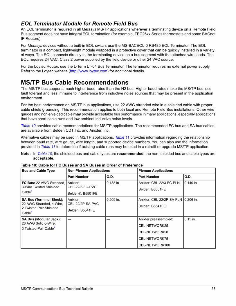
EOL Terminator Module for Remote Field BusAn EOL terminator is required in all Metasys MS/TP applications wherever a terminating device on a Remote FieldBus segment does not have integral EOL termination (for example, TEC26xx Series thermostats and some BACnetIP Routers).
For Metasys devices without a built-in EOL switch, use the MS-BACEOL-0 RS485 EOL Terminator. The EOLterminator is a compact, lightweight module wrapped in a protective cover that can be quickly installed in a varietyof ways. The EOL connects directly to the terminating device on a bus segment with the attached wire leads. TheEOL requires 24 VAC, Class 2 power supplied by the field device or other 24 VAC source.
For the Loytec Router, use the L-Term LT-04 Bus Terminator. The terminator requires no external power supply.Refer to the Loytec website (http://www.loytec.com) for additional details.
MS/TP Bus Cable RecommendationsThe MS/TP bus supports much higher baud rates than the N2 bus. Higher baud rates make the MS/TP bus lessfault tolerant and less immune to interference from inductive noise sources that may be present in the applicationenvironment.
For the best performance on MS/TP bus applications, use 22 AWG stranded wire in a shielded cable with propercable shield grounding. This recommendation applies to both local and Remote Field Bus installations. Other wiregauges and non-shielded cablemay provide acceptable bus performance in many applications, especially applicationsthat have short cable runs and low ambient inductive noise levels.
Table 10 provides cable recommendations for MS/TP applications. The recommended FC bus and SA bus cablesare available from Belden CDT Inc. and Anixter, Inc.
Alternative cables may be used in MS/TP applications. Table 11 provides information regarding the relationshipbetween baud rate, wire gauge, wire length, and supported device numbers. You can also use the informationprovided in Table 11 to determine if existing cable runs may be used in a retrofit or upgrade MS/TP application.
Note: In Table 10, the shielded bus and cable types are recommended; the non-shielded bus and cable types areacceptable.
Table 10: Cable for FC Buses and SA Buses in Order of PreferencePlenum ApplicationsNon-Plenum ApplicationsBus and Cable Type
O.D.Part NumberO.D.Part Number
0.140 in.Anixter: CBL-22/3-FC-PLN
Belden: B6501FE
0.138 in.Anixter:CBL-22/3-FC-PVC
Belden®: B5501FE
FC Bus: 22 AWG Stranded,3-Wire Twisted ShieldedCable1
0.206 in.Anixter: CBL-22/2P-SA-PLN
Belden: B6541FE
0.209 in.Anixter:CBL-22/2P-SA-PVC
Belden: B5541FE
SA Bus (Terminal Block):22 AWG Stranded, 4-Wire,2 Twisted-Pair ShieldedCable1
0.15 in.Anixter preassembled:
CBL-NETWORK25
CBL-NETWORK50
CBL-NETWORK75
CBL-NETWORK100
——SA Bus (Modular Jack):26 AWG Solid 6-Wire,3 Twisted-Pair Cable2
35MS/TP Communications Bus Technical Bulletin

Table 10: Cable for FC Buses and SA Buses in Order of Preference0.131 in.Belden: B6501UE0.135 in.Belden: B5501UEFC Bus: 22 AWG Stranded,
3-Wire Twisted Non-ShieldedCable
0.199 in.Belden: B6541UE0.206 in.Belden: B5541UESA Bus (Terminal Block):22 AWG Stranded, 4-Wire,2 Twisted-Pair Non-ShieldedCable
1 We strongly recommend 3-wire (for FC bus) and 4-wire, 2 twisted-pair (for SA bus), 22 AWG stranded, shielded cable. A 22gauge cable offers the best performance for various baud rates, cable distances, and number of trunk devices primarily dueto lower conductor-to-conductor capacitance. Shielded cable offers better overall electrical noise immunity than non-shieldedcable. Observe the shield grounding requirements.
2 We recommend 26 AWG solid, 6-wire (3 twisted pairs) cable as the best fit for fabricating modular cables with the modularjack housing assembly. Be sure the cable you use fits the modular jack housing. The preassembled cables that are availablefrom Anixter (Part No. CBL-NETWORKxxx) use 24 gauge wire.
Table 11: FC Bus Wire Gauge and FC Bus Baud RateBaud RateMaximum Cable Length and
Node Connections LimitAWG WireGauge
76,800 338,400 219,200 19600 1
305(1,000)
(NR)
609(2,000)
(NR)
1,219(4,000)
(NR)
1,219(4,000)
(NR)
1,524 (5,000)
(APR)
1,524 (5,000)
(APR)
Maximum Cable Length perBus Segment (m [ft])
18
50/100
(NR)
10/30
(NR)
50/100
(NR)
40/100
(NR)
50/50
(APR)
25/25
(APR)
Maximum Number of Nodes(per Segment / per FC Bus)
1,219(4,000)
(NR)
1,524(5,000)
(NR)
1,524 (5,000)
(APR)
1,524 (5,000)
(APR)
1,524 (5,000)
(APR)
Maximum Cable Length perBus Segment (m [ft])
20
50/100
(NR)
40/100
(NR)
50/100
(APR)
50/50
(APR)
25/25
(APR)
Maximum Number of Nodes(per Segment / per FC Bus)
1,524 (5,000)
(A)
1,524 (5,000)
(Best)
1,524 (5,000)
(A)
1,524 (5,000)
(A)
Maximum Cable Length perBus Segment (m [ft])
22
50/100
(A)
50/100
(Best)
50/50
(A)
25/25
(A)
Maximum Number of Nodes(per Segment / per FC Bus)
1,524 (5,000)
(APR)
1,524 (5,000)
(APR)
1,524 (5,000)
(APR)
1,524 (5,000)
(APR)
Maximum Cable Length perBus Segment (m [ft])
24
50/100
(APR)
50/100
(APR)
50/50
(APR)
25/25
(APR)
Maximum Number of Nodes(per Segment / per FC Bus)
36MS/TP Communications Bus Technical Bulletin

Table 11: FC Bus Wire Gauge and FC Bus Baud Rate1,524 (5,000)
(APR)
1,524 (5,000)
(APR)
1,524 (5,000)
(APR)
1,524 (5,000)
(APR)
Maximum Cable Length perBus Segment (m [ft])
26
50/100
(APR)
50/100
(APR)
50/50
(APR)
25/25
(APR)
Maximum Number of Nodes(per Segment / per FC Bus)
A = Acceptable
APR = Acceptable with Possible Restrictions
NR = Not Recommended
1 The maximum number of devices is reduced at lower baud rates due to increased token loop times.2 3-wire conductor (FC Bus), 22 AWG stranded, shielded cable is recommended. 22 gauge cable offers the best performance
for various baud rates, cable distances, and number of trunk devices primarily due to lower conductor-to-conductor capacitance.Shielded cable offers better overall electrical noise immunity than non-shielded cable.
3 The MS-NAE55xx-0 cannot communicate at 76,800 baud.
Screw Terminal Blocks for Connecting FC and SA Bus CablesBoth the FC bus and SA bus terminations have pluggable screw terminal blocks that allow you to connect the busdevices in a daisy-chain configuration. Connect the devices to the FC bus segments and SA bus as shown in Figure16 .
Note: • The SHLD terminal on the FC bus terminal block is electrically isolated from ground and is provided asa convenient terminal for connecting the cable shield in a daisy-chain on the bus segment.
• Do not mix RJ-style modular (phone) jack and screw terminal devices on the SA bus. Due to the permanentinternal SA bus EOL termination contained in FECs, FACs, IOMs, and VMAs, using both the phone jackand terminal block effectively puts the EOL termination in the middle of the SA trunk, creating a starnetwork configuration. This configuration violates the RS-485 network wiring guidelines and can causeunpredictable communication problems.
• Certain MS-IOM models have gray SA/FC terminal blocks rather than blue or brown.
Figure 16: FC Bus and SA Bus Terminal Block Wiring Details
37MS/TP Communications Bus Technical Bulletin

Grounding the MS/TP Bus Cable ShieldInductive interference and Radio Frequency (RF) interference can adversely affect MS/TP applications, causingpoor bus performance and frequent device offline occurrences. Experience has shown that installing a properlygrounded shielded bus cable in MS/TP applications greatly reduces the impact of ambient inductive noise and RFinterference. Applications installed without shielded cable are much less tolerant to ambient interference.
We recommend installing MS/TP bus applications using shielded cable. In applications using shielded cable, it isvery important to ground the cable shield properly. Improper shield grounding can also result in poor bus performanceand frequent device offline occurrences.
To properly ground the cable shield on an MS/TP application, the cable shields on each bus segment must beconnected in a daisy-chain as shown in Figure 16. Each daisy-chained segment must be connected at one point(only) to a hard ground connection. We recommend connecting the cable shield to hard ground close to the bussupervisor’s bus terminations. In metal panel or enclosure applications, connect the cable shield to ground wherethe bus cable enters the panel or enclosure that contains the bus supervisor. On bus segments without a bussupervisor, the best practice is to connect the cable shield to hard ground at a bus device near the middle of thebus segment.
Important: Ensure that the cable shield is connected to hard ground at only one point on the bus segmentand is completely isolated from hard ground at all other points. Multiple hard ground connections on abus segment can create ground loop currents in the cable shield, resulting in poor bus performanceand frequent device offline occurrences.
In certain environments with high ambient inductive interference or strong radio frequency transmissions, an MS/TPapplication may require the addition of soft ground connections along the bus segments to enhance bus performanceand reduce device offline occurrences, or possible device damage.
Examples of potential inductive interference include large motors, contactors, relays, welding equipment, high-voltageconductors that are not in metal conduit or raceways, other high wattage devices within 10 m (30 ft) of the bus cable,and areas of frequent lightning.
Examples of potential radio frequency interference include locations near airports, hospitals, radio or televisiontransmission towers, police and fire stations, or factories. Mobile transmitters in police, fire, emergency, and fleetvehicles are also potential sources of radio frequency interference.
Note: Themajority of properly groundedMS/TP applications do not require soft ground connections, but you shouldassess the potential interference that your application may encounter (before you install the bus). It is moreefficient to prepare for soft ground connections when making the bus terminations at the initial installationthan to return and do it later.
Soft ground connections should be made within 2 inches of the bus terminations of any bus device that experiencesfrequent offline occurrences resulting from high ambient inductive or RF interference (Figure 17).
38MS/TP Communications Bus Technical Bulletin
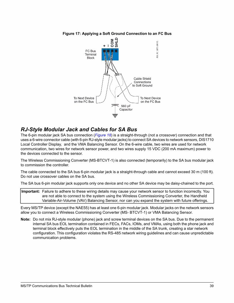
Figure 17: Applying a Soft Ground Connection to an FC Bus
RJ-Style Modular Jack and Cables for SA BusThe 6-pin modular jack SA bus connection (Figure 18) is a straight-through (not a crossover) connection and thatuses a 6-wire connector cable (with 6-pin RJ-style modular jacks) to connect SA devices to network sensors, DIS1710Local Controller Display, and the VMA Balancing Sensor. On the 6-wire cable, two wires are used for networkcommunication, two wires for network sensor power, and two wires supply 15 VDC (200 mA maximum) power tothe devices connected to the sensor.
The Wireless Commissioning Converter (MS-BTCVT-1) is also connected (temporarily) to the SA bus modular jackto commission the controller.
The cable connected to the SA bus 6-pin modular jack is a straight-through cable and cannot exceed 30 m (100 ft).Do not use crossover cables on the SA bus.
The SA bus 6-pin modular jack supports only one device and no other SA device may be daisy-chained to the port.
Important: Failure to adhere to these wiring details may cause your network sensor to function incorrectly. Youare not able to connect to the system using the Wireless Commissioning Converter, the HandheldVariable-Air-Volume (VAV) Balancing Sensor, nor can you expand the system with future offerings.
Every MS/TP device (except the NAE55) has at least one 6-pin modular jack. Modular jacks on the network sensorsallow you to connect a Wireless Commissioning Converter (MS- BTCVT-1) or VMA Balancing Sensor.
Note: Do not mix RJ-style modular (phone) jack and screw terminal devices on the SA bus. Due to the permanentinternal SA bus EOL termination contained in FECs, FACs, IOMs, and VMAs, using both the phone jack andterminal block effectively puts the EOL termination in the middle of the SA trunk, creating a star networkconfiguration. This configuration violates the RS-485 network wiring guidelines and can cause unpredictablecommunication problems.
39MS/TP Communications Bus Technical Bulletin

Figure 18: 6-Pin Modular Jack Pinout Details
Commissioning Devices on the FC BusCommission the devices on the local and remote MS/TP buses using the CCT software. Refer to CCT Help(LIT-12011147) for information on commissioning an MS/TP bus application.
Applications and device configurations are downloaded to the hardware from the CCT computer using the WirelessCommissioning Converter or through the NAE, NCE, or Open Data Server (ODS) from the Metasys UI. Refer to theBACnet® Controller Integration with NAE/NCE Technical Bulletin (LIT-1201531) for more information.
Hardware points can be auto discovered from the online UI of the NAE, the Application and Data Server (ADS), theExtended Application and Data Server (ADX), or the Open Data Server (ODS).
Peer-to-Peer CommunicationPeer-to-peer communication allows non-supervisory engines on a bus to communicate system data with each otherdirectly, bypassing the supervisory engines (NAE/NCE) on the bus.
Related DocumentationTable 12 lists the related documentation that describes controllers and systems related to the MS/TP communicationsbus.
Table 12: Related DocumentationSee DocumentFor Information OnMetasys® System Configuration Guide (LIT-12011832)Metasys® System Limitations and Overview
NAE55/NIE55 Installation Instructions (Part No. 24-10051-43)Installation and Specifications of the NAE55
NAE35/NAE45 Installation Instructions (Part No. 24-10050-6)Installation and Specifications of the NAE45 or NAE35
NCE25 Installation Instructions (Part No. 24-10143-63)Installation and Specifications of the NCE25
Metasys® System Field Equipment Controllers and RelatedProducts Product Bulletin (LIT-12011042)
Specifications of theMetasys® System Field Controllers
40MS/TP Communications Bus Technical Bulletin
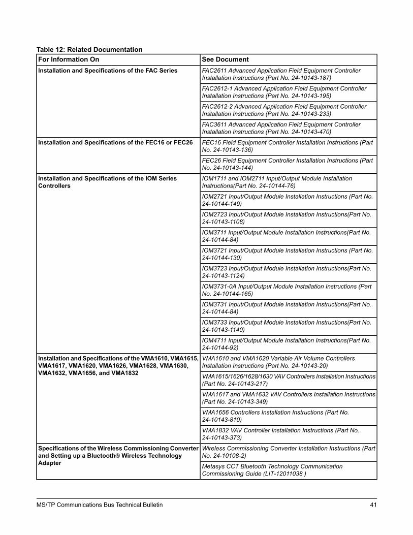
Table 12: Related DocumentationSee DocumentFor Information OnFAC2611 Advanced Application Field Equipment ControllerInstallation Instructions (Part No. 24-10143-187)
Installation and Specifications of the FAC Series
FAC2612-1 Advanced Application Field Equipment ControllerInstallation Instructions (Part No. 24-10143-195)
FAC2612-2 Advanced Application Field Equipment ControllerInstallation Instructions (Part No. 24-10143-233)
FAC3611 Advanced Application Field Equipment ControllerInstallation Instructions (Part No. 24-10143-470)
FEC16 Field Equipment Controller Installation Instructions (PartNo. 24-10143-136)
Installation and Specifications of the FEC16 or FEC26
FEC26 Field Equipment Controller Installation Instructions (PartNo. 24-10143-144)
IOM1711 and IOM2711 Input/Output Module InstallationInstructions(Part No. 24-10144-76)
Installation and Specifications of the IOM SeriesControllers
IOM2721 Input/Output Module Installation Instructions (Part No.24-10144-149)
IOM2723 Input/Output Module Installation Instructions(Part No.24-10143-1108)
IOM3711 Input/Output Module Installation Instructions(Part No.24-10144-84)
IOM3721 Input/Output Module Installation Instructions (Part No.24-10144-130)
IOM3723 Input/Output Module Installation Instructions(Part No.24-10143-1124)
IOM3731-0A Input/Output Module Installation Instructions (PartNo. 24-10144-165)
IOM3731 Input/Output Module Installation Instructions(Part No.24-10144-84)
IOM3733 Input/Output Module Installation Instructions(Part No.24-10143-1140)
IOM4711 Input/Output Module Installation Instructions(Part No.24-10144-92)
VMA1610 and VMA1620 Variable Air Volume ControllersInstallation Instructions (Part No. 24-10143-20)
Installation and Specifications of the VMA1610, VMA1615,VMA1617, VMA1620, VMA1626, VMA1628, VMA1630,VMA1632, VMA1656, and VMA1832 VMA1615/1626/1628/1630 VAVControllers Installation Instructions
(Part No. 24-10143-217)
VMA1617 and VMA1632 VAV Controllers Installation Instructions(Part No. 24-10143-349)
VMA1656 Controllers Installation Instructions (Part No.24-10143-810)
VMA1832 VAV Controller Installation Instructions (Part No.24-10143-373)
Wireless Commissioning Converter Installation Instructions (PartNo. 24-10108-2)
Specifications of theWireless Commissioning Converterand Setting up a Bluetooth® Wireless TechnologyAdapter Metasys CCT Bluetooth Technology Communication
Commissioning Guide (LIT-12011038 )
41MS/TP Communications Bus Technical Bulletin

Table 12: Related DocumentationSee DocumentFor Information OnBACnet® Controller Integration with NAE/NCE/ODS TechnicalBulletin (LIT-1201531)
Integrating BACnet® MS/TP and BACnet IP Devices intothe Metasys System Network
MS-BACEOL-0 RS485 End-of-Line Terminator InstallationInstructions (Part No. 24-10264-4)
Installation of and Specifications for the MS-BACEOL-0End-of-Line Terminator Module
LIP-ME201 User Manual. Refer to http://www.loytec.comWiring and Configuration for the Loytec BACnet Router
ZFR1800 Series Wireless Field Bus System Technical Bulletin(LIT-12011295)
Designing, Installing, Commissioning, Operating, andTroubleshooting a ZFR1800 Series System on aMetasysNetwork
ZFR1810 Wireless Field Bus Coordinator Installation Instructions(Part No. 24-10325-2)
Locating, Mounting, and Wiring ZFR1810 Coordinatorsand ZFR1811 or ZFR1812 Routers
ZFR1811 Wireless Field Bus Router Installation Instructions (PartNo. 24-10325-10)
Locating, Mounting, and Wiring ZFR1811 or ZFR1812Routers
ZFR1812 Wall Mount Wireless Field Bus Router InstallationInstructions (Part No. 24-10325-45)
Locating, Mounting, and Wiring ZFR1812 Routers
WRZ-TTx SeriesWireless Room Temperature Sensors InstallationInstructions (Part No. 24-10332-2 )
Locating and Installing WRZ-TTx Series Sensors
ZFR1800 Series Wireless Field Bus System Product Bulletin(LIT-12011336)
Applications, Features, and Benefits of the ZFR1800Series Wireless Field Bus System
Wireless Metasys System Location Guide (LIT-12011294)1Estimating Quantity, Locating, and Testing ZFR1800,Coordinators, ZFR1811 or ZFR1812 Routers, andWRZ-TTx Series Sensors
Controller Tool Help (LIT-12011147)2Controller Configuration Tool (CCT) Software
Metasys IP Network for IP VMAs and IP Controllers - ConfigurationGuide (LIT-12012458)
Information on BACnet/IP networks with Metasyssystems.
1 This document is only available on the Johnson Controls® Portal intranet site.2 This LIT number represents a printer-friendly version of the Help.
Appendix: FC Bus Auxiliary Devices
RepeatersRepeaters are optional components on the FC bus that increase the maximum allowable length and device countsof the FC bus. One repeater is counted as one device on the FC bus. Repeaters are not allowed on the SA Bus.Table 13 describes how the length and device maximums of the bus change when you add repeaters. The repeateris specified in Local FC Bus Rules and Specifications.
A maximum of two repeaters can be between any two points on the FC bus.
Note: Some device models and third-party devices may have reduced capabilities.
Table 13: Repeaters on the FC BusWith 2 RepeatersWith 1 RepeaterWith No RepeaterMaximums1,2
5,0005,0005,000Maximum Segment Length (ft)
15,00010,0005,000Maximum Total Length (ft)
505050Maximum Device Count Per Segment
10010050Maximum Total Device Count
1 The values in this table represent the recommended 3 conductor, 22 AWG stranded, shielded cable.2 Some device models and third-party devices may have reduced capabilities.
42MS/TP Communications Bus Technical Bulletin

Configuring RepeatersThe instructions for configuring the repeater for use with the FC bus require that you perform the following:
• Set the baud rate to match the FC bus baud rate.• Wire the repeater between two segments of the MS/TP bus. If you are using this repeater in a branch, the side
with the branch has double the number of wires terminated. See Figure 19.• Set the EOL jumpers on the repeater according to Table 14.
Note: The EOL jumpers are located below the cover of the repeater.
Note: Sides A and B have separate EOL settings. Determine the settings individually.
For repeater installation instructions and important safety information, refer to the repeater manufacturer’s literature.
Risk of Electric Shock: Disconnect or isolate all power supplies before making electrical connections. More thanone disconnection or isolation may be required to completely de-energize equipment. Contact with componentscarrying hazardous voltage can cause electric shock and may result in severe personal injury or death.
Table 14: EOL Settings for RepeaterInstructionsJumperSideAt end-of-line: Install both jumpers over Pins 1 and 2 (EOL In).J1 and J2Side A
Not at end-of-line: Install both jumpers over Pins 2 and 3 (EOL Out).
At end-of-line: Install both jumpers over Pins 1 and 2 (EOL In).J3 and J4Side B
Not at end-of-line: Install both jumpers over Pins 2 and 3 (EOL Out).
43MS/TP Communications Bus Technical Bulletin

Figure 19: Configuring the Repeater
Fiber-Optic ModemsYou can install the 2110BAC fiber-optic modems in any location on the FC bus. Just as only two repeaters can becascaded on the FC bus, only two pairs of 2110BAC modems can be cascaded.
The first installation step is to route the optical fiber and connect each modem to the ends of the fiber. The secondstep is to connect the FC bus on both sides of the modems.
Routing and Connecting the Fiber CablesTo route and connect the fiber cables, follow these steps and see Figure 20:
1. Route the optical fiber in a manner that is required for the application.2. Connect the fiber cable from the T (Transmit) output of the modem nearest to the NxE to the R (Receive) input
of the modem near the MS/TP devices.3. Connect the fiber cable from the T (Transmit) output of the modem near the MS/TP devices to the R (Receive)
input on the modem nearest to the NxE.4. Plug in the power supply for each modem.
44MS/TP Communications Bus Technical Bulletin

Figure 20: Connecting the 2110 Modems
Connecting Modems to MS/TP BusConnect the MS/TP bus to the 2110BAC modem by soldering the MS/TP wires to pins on the 9-pin connector, whichcan also configure the modem as an EOL device. To connect the bus, see Setting Termination on Fiber Modems.
Note: A DIN rail mounting version of the Model 2110BAC may be available as Model 2110BAC-DIN. This modelwould not require soldering the MS/TP wires. However, Model 2110BAC-DIN does not appear on the S.I.Tech web site at the time of this writing. Contact S.I. Tech using contact information on their web site athttp://www.sitech-bitdriver.com/index.htm.
Fiber Modem between Two SegmentsIf you need to place the 2110BAC modem between two segments of MS/TP bus, wire a stub length of 6 inches orless, as shown in Figure 21, and terminate the two pairs of MS/TP bus cable at the end of the stub length.
If the fiber modem is at the end of a segment, set the EOL to In.Important: If the fiber modem is at the end of a network segment (one wire connected) then you must use the
built-in termination. Failure to use the built-in termination will affect the biasing and other electricalcharacteristics of the trunk.
45MS/TP Communications Bus Technical Bulletin

Figure 21: Connecting 2110BAC Modem in between Two MS/TP Bus Segments
Setting Termination on Fiber ModemsThe 2110BAC modem does not have an EOL jumper. Instead, establish EOL termination on a 2110BAC modemby properly terminating the FC bus wires to the 9-pin connector. Soldering the wires to specific pins and solderingtwo jumper wires configures the modem as an end-of-line device (see Figure 22, Figure 23, and Table 15 for moreinformation).Note: A DIN rail mounting version of the Model 2110BAC may be available as Model 2110BAC-DIN. This model
would not require soldering the MS/TP wires. However it does not appear on the S.I. Tech web site at thetime of this writing. Contact S.I. Tech using contact information on their web site athttp://www.sitech-bitdriver.com/index.htm.
Do not set the fiber modem as an EOL device on the SA bus.
Modem Set EOL to InTo set the modem as an end-of-line device, wire the 9-pin connector using solder connections as shown in Figure22.Important: If the fiber modem is at the end of a network segment (one wire conected) then you must use the
built-in termination. Failure to use the built-in termination will affect the biasing and other electricalcharacteristics of the trunk.
Note: The following figure shows the 9-pin female connector. The pin numbers on the 9-pin male connector arereversed.
46MS/TP Communications Bus Technical Bulletin

Figure 22: Female Modem Cable Connector: EOL Set to In
Modem Set EOL to OutTo set the modem with the end-of-line selection set to Out, wire the 9-pin connector using solder connections as inFigure 23.
Note: The following figure shows the 9-pin female connector. The pin numbers on the 9-pin male connector arereversed.
Figure 23: Female Modem Cable Connector: EOL Set to Out
Table 15: EOL Connections SummarizedFor Non-EOL SelectionFor EOL SelectionFC Bus SignalTerminal 3Terminal 7, Jumper 7-3FC +
Terminal 9Terminal 8, Jumper 8-9FC -
Terminal 1 or 5Terminal 1 or 5REF
Tape BackTape BackSHIELD
47MS/TP Communications Bus Technical Bulletin

Surge ProtectorsSurge protection is strongly recommended if the MS/TP bus is wired between buildings. The protection is providedby a voltage surge suppressor, which is installed on the MS/TP bus near the MS/TP device. Example applicationsare shown in Figure 24.
Figure 24: Surge Protector Installation on MS/TP Bus
Note: Fiber-optic bus connections between buildings are immune to transient voltage and other problems associatedwith hard-wire bus connections. Fiber-optic bus connections do not require surge protection and may be lesscostly to install. See Fiber-Optic Modems for information.
The recommended surge protector is the Transient Eliminator, model TE/JC04C12, manufactured by AdvancedProtection Technologies, Inc. (APT). The device protects the MS/TP bus from indirect lightning, and shunts bothcommon and normal mode voltage surges to ground repeatedly without damage to MS/TP bus components.
Important: The surge protector is capable of protecting the MS/TP bus from indirect lightning strikes, not directlightning strikes. A direct strike may cause actual damage to the bus cable or surrounding property.An indirect lightning strike may cause induced voltage transients that could cause electronic malfunctionwithout visible damage to equipment if the equipment were not protected.
Use the surge protector with the standard MS/TP bus wiring. Do not use it with any other type wiring such as leasedline. If you need surge protection for other wire types, contact APT or another transient noise protection company.
Table 16 lists the specifications of the surge protector.
Table 16: Surge Protector SpecificationsSpecificationCategoryTransient EliminatorProduct Name
Surge ProtectorGeneric Name
TE/JC04C12Model Number
Three stage solid-state design using both metal oxide varistorsand silicon avalanche diodes for suppression
Design
Less than 1 nanosecondResponse Time
48MS/TP Communications Bus Technical Bulletin

Table 16: Surge Protector SpecificationsSpecificationCategory10 kA per conductorMaximum Impulse Current (8/20 ms current impulse)
80 Joules per conductor (10/1000 us)Maximum Energy Dissipation
12 VDCMaximum Operating Voltage
Common and normal modesProtection
100 kHz ringwave at 200 A: 15.8 volts 100 kHz ringwave at 500A: 16.8 volts 3 kA combination wave: 20.8 volts
Suppression Voltage Levels (Common mode)
One pair per bus segmentMaximum Number of Protectors Allowed on MS/TP Bus
1,524 m (5,000 ft) (standard MS/TP bus specification)Maximum Length of MS/TP Bus Between Two BuildingsUsing Protector
Encapsulated in Ceramgard® composition for insulation andenvironmental protection. Two-part design for easy connectionand replacement of protective device to base using edgeconnector. Durable UL Recognized plastic enclosure material
Other Mechanical Features
63.5 x 50.8 x 25.4 mm (2.5 x 2.0 x 1.0 in.)Dimensions (H x W x D)
One pair of surge protectors is required whenever the MS/TP bus wire is routed outside between two buildings. APTrecommends that you install the protector close to the MS/TP device that first receives the bus wires from the outside.Figure 25 shows an FC bus surge protector wiring example.
The protector does not require that you use any special type of wire for the MS/TP bus, such as double-shieldedtwisted cable. Use the standard recommended twisted cable types.
49MS/TP Communications Bus Technical Bulletin

Figure 25: FC Bus Surge Protector Wiring Example
50MS/TP Communications Bus Technical Bulletin

The surge protector consists of two sections: the terminal block and the main assembly. These sections separateto make the unit easier to install and replace (Figure 26).
Figure 26: Sections of Surge Protector
The surge protector is wired depending on which device requires protection. Follow these general steps:
1. Mount the Transient Eliminator device per local codes. Install in an enclosure (if required) as close as possibleto the first MS/TP device connecting the trunk segment entering the building. Any electrical box with a cover isacceptable. Bond the transient eliminator enclosure to the MS/TP device enclosure by connecting the two withthe conduit that carries the MS/TP cable.
2. Connect the MS/TP segment from the outside to the unprotected side of the device. If possible, run the segmentinside metallic conduit because the conduit acts like a shield for lightning.
3. Connect the MS/TP segment that goes to the MS/TP device to the protected side of the device. Keep this segmentaway from the unprotected segment.
4. Connect the protector to earth ground with 12 AWG stranded green wire (Figure 25). The total length of groundwire cannot exceed 4.57 m (15 ft), which means an earth ground must be available within 4.57 m (15 ft) of theMS/TP device. (Your installation design must accommodate this requirement.)
5. For hard ground installation, connect the shield to Pin 9. For soft ground installation, connect the shield to Pin7.
For more details on installation, refer to the specific manufacturer’s literature.
Appendix: Maximizing and Troubleshooting the MS/TP Bus
Maximizing TipsObserve the following guidelines to maximize the performance of an MS/TP bus.
51MS/TP Communications Bus Technical Bulletin

DescriptionGuidelineCOV reports account for the highest amount of traffic on the bus. For bestperformance, keep the COV rate at 500 COVs per minute or fewer for each network.To reduce the COV traffic:
• Set the COV increment to the largest value that still provides acceptableperformance.
• Do not map more points to the NxE than are required.
For mapped analog points, where the values are changing frequently, consider thefollowing to limit COV reports:
• Increase the COV increment on the point.
Note: For some Analog Inputs (AIs), this value cannot be modified.
• Set the Use Cov Min Send Time flag to true, which causes the COVs to besent on a timed basis. The time value is specified in the controller device object.
Limit the Number of Change of Value(COV) Report Rates over the MS/TP Bus
Subordinate devices on the FC bus are not supported. The SA bus only supportsa specific set of subordinate devices.
DoNot Place Subordinate Devices on theFC Bus
Third-party devices can seriously degrade both hardware and software performancedepending on their quality and configuration. Consider and configure third-partydevices carefully according to the manufacturer’s specifications.
Carefully Evaluate Third-Party Devices
Once the system is configured, commissioned, and running, avoid adding extratraffic to the bus by performing unnecessary auto-discovery operations, downloads,or bus analysis.
Do Not Add Extra Traffic
Follow the wiring rules carefully. The tolerances of the MS/TP bus are tighter thanother, slower protocols may be. Improper terminations may result in errors causingserious network degradation. See MS/TP Bus Cable Recommendations.
Observe the MS/TP Wiring Guidelines
See Statistics Attributes.Check the MS/TP Statistics for Errors
Avoid changing default MS/TP bus settings, especially settings youmay be unfamiliarwith. Some parameters set improperly or randomly can cripple the MS/TP buscompletely.
Use Default MS/TP Settings
MS/TP Bus Health Factors of the Diagnostics TabThe Diagnostics tab of the MS/TP field bus integration, viewed from the Metasys system UI, provides a snapshot ofthe condition of the bus. The attributes that are most illustrative of the bus condition are the Bus Health Index andBus Performance Index attributes, both located under Calculations (Figure 27). The Statistics attributes also providea useful look into the condition of the MS/TP bus.
52MS/TP Communications Bus Technical Bulletin

Figure 27: MS/TP Object Diagnostic Tab
Bus Health IndexThe Bus Health Index is a snapshot of the immediate number of errors on the bus. This index provides a weightedmoving average of four MS/TP bus error counters: Framing Errors, Header CRC Errors, Data CRC Errors, andLost Tokens. The ideal value for the Bus Health Index is zero.
Because the average is reevaluated every 30 seconds, the average gradually returns to zero if no new errors occur.As such, if errors occur only periodically (for example, only when a source of bus interference [such as a welder] isin use), the Bus Health Index may return to zero before you see the value indicate that there are errors. If you suspectthat errors are occurring, look at the four error counter attributes. Alternatively, you can trend the Bus Health Indexto see when or if it changes during the course of the day.
TheWeighted Bus Health Constant attribute is an adjustment factor that determines how quickly the Bus HealthIndex returns to zero if there are no new errors. The smaller the value of the constant, the slower the index returnsto zero.
Typically, the errors indicated by the Bus Health Index are physical bus problems. See Correcting Physical BusProblems.
53MS/TP Communications Bus Technical Bulletin

Bus Performance IndexThe Bus Performance Index provides a snapshot of the performance of the network by taking the weighted movingaverage of the ratio of the actual loop time to the predicted loop time.
TheWeighted Bus Performance Constant attribute is an adjustment factor that determines how quickly the indexchanges when the actual loop time changes.
Because a master device is allowed to originate messages only when it holds the token, the token loop time is closelyrelated to network performance. During normal operation, the token loop time should not exceed 2 seconds (2,000milliseconds). Special Operations (such as Auto Discovery, device downloads, or bus analysis) may cause the looptime to exceed this value temporarily, but this is no cause for concern; unless, the token loop time continually exceeds2 seconds, then the bus may be experiencing excessive errors or data overload. The 2-second loop time figure isthe upper limit of an ideal token loop time; however, the Bus Performance Index predicts what the token loop timeshould be, based on the number of devices, the baud rate, and the number of messages.
The ideal value for the Bus Performance Index is 1. Table 17 provides the guidelines of the Bus Performance Index.
Table 17: Bus Performance IndexDescriptionIndex ValueBest performance, no performance problems1.0 - 1.9
Acceptable performance2.0 - 2.9
Possible slower performance, bus may be overloaded3.0 - 5.9
Poor performance, devices going offline, other problems6.0 or Greater
High numbers (around 6 and higher) can indicate a physical problem or that the bus communication is overloaded.If the Bus Health Index is zero, the problem is probably due to an overloaded bus. See Correcting Bus OverloadProblems.
Statistics AttributesThe Statistics attributes of the MS/TP Field Bus Integration object Diagnostics tab (Advanced View) provide usefulinformation about what is happening on the MS/TP bus. Table 18 describes some of the attributes and values thatindicate there is a problem on the bus. For more details on the following attributes, refer to the MS/TP Field BusIntegration Attributes section of the Metasys system Help (LIT-1201793).
Send the Latch Statistics command to the MS/TP field bus integration before comparing your values to Table 18.If the statistics have already been latched and represent old data, send theClear Statistics command. Wait a minuteor longer for new data to accumulate and send the Latch Statistics command.
For more information on statistics, refer to the Metasys system Help (LIT-1201793).
Table 18: Statistics AttributesError Condition IndicatedAttributePossible network disruptionUnexpected Frames Rxed
Noise, bad wiring, or another device did not respond.Packets Timed Out
Noise, bad wiring, or mismatched baud ratesFraming Errors
This node is too busy.Overrun Errors
Noise or bad wiringHeader CRC Errors
Noise or bad wiringData CRC Errors
Another device is slow to respond.Reply Too Slow Datalink Errors
The node is too busy to build the reply at this time.Reply Too Slow Application Errors
Low memory or unexpected conditionsInternal Errors
54MS/TP Communications Bus Technical Bulletin

Table 18: Statistics AttributesError Condition IndicatedAttributeThe node is trying to send or receive too much at this time.Buffer Overflows
Network disruption (includes initial startup, so 1 is common)Lost Token
Problems passing the token messageRetries
Analyze Field Bus CommandThe Analyze Field Bus command provides detailed information about the devices that currently reside on the localor remote MS/TP bus. The command tells the NAE to poll each address on the FC bus, in order from 1 to 254. Thepolling takes several minutes to complete. Once it finishes, the Bus Analysis Progress attribute reads Complete andthe Bus Device Configuration List displays each device on the bus.
Note: To use the Analyze Field Bus command on a Remote Field Bus, at least one of the MS/TP field controllersmust be an FEC family Metasys device.
This command attempts to show the address, make, and other attributes of each device on the bus. You can usethis information to identify devices you are unaware of and to identify third-party devices on the bus. The results ofthe scan can vary depending on the device type and manufacturer of the devices on the bus.
To issue the Analyze Field Bus command:
1. Right-click theMS/TP Field Bus Integration object in the navigation tree and selectCommands from the pop-upmenu. The Select Command dialog box appears.
2. Select Analyze Field Bus and click Send. The Bus Analysis Progress attribute value changes to In Progress.3. After the Bus Analysis Progress changes to Complete, read the devices from the Bus Device Configuration
List drop-down menu (Figure 28) using Table 19.
Figure 28: Bus Device Configuration List Example
55MS/TP Communications Bus Technical Bulletin

Table 19: Bus Device Configuration ListPossible Values/Exception ValuesDescriptionLabelAny name or numberDisplays the name of the field device. The name is
derived from following in this order:
1. If the field device appears in the navigation tree,the name on the tree is used initially.
2. If the device is communicating on the field bus,its name is read directly and overwrites thecurrent name.
3. If the device does not appear on the navigationtree and it is communicating, but its namecannot be read, the field is left blank.
Object Name
1 – 255Displays the MS/TP address of a device if thedevice appears in the navigation tree or the deviceresponds to the analyze field bus command poll.
Address
True indicates that the device is mapped andappears on the navigation tree. False indicatesthat the device is not mapped and does notappear on the navigation tree.
Note: Currently, the Device Mapped labelonly applies to the FEC, FAC, IOM, andVMA16 Series controllers. Otherdevices may return a False value eventhough they are mapped and appearon the navigation tree.
Indicates whether devices are mapped to theMetasys system.
Mapped
Responding indicates that the deviceresponded to the poll. No Response indicatesthat the device appears in the navigation treebut did not respond to the poll.
Indicates whether the device responded to theanalyze bus poll.
Status
<127 indicates that the Max Master attributehas been altered. See Parameters That AffectMS/TP Communication.
127 is the default value and indicates that thedevice is configured.
255 indicates that the poll could not read theMax Master attribute.
Displays the Max Master attribute of the device. Ifthe device is configured, the default value is 127.If the attribute cannot be read, the value displayedis 255.
Max Master
10 is the default value and indicates that thedevice is configured.
255 indicates that the poll could not read theMax Info Frames attribute.
Displays the Max Info Frames attribute of thedevice. If the device is configured, the default valueis 10. If the attribute cannot be read, the valuedisplayed is 255.
Max Info Frames
56MS/TP Communications Bus Technical Bulletin

Table 19: Bus Device Configuration ListPossible Values/Exception ValuesDescriptionLabelBoot indicates that the device is starting andis not completely functional.
Main indicates that the device is functional andoperating.
Unknown indicates that the device is notresponding or does not support the Code Stateattribute.
Indicates the state of the operating code withinJohnson Controls® field devices. This field ismeaningful only for Johnson Controls field devices.
Code State
True indicates the FEC, FAC, IOM, and VMA16EOL switch is On.
False indicates the FEC, FAC, IOM, andVMA16 EOL switch is Off.
Note: All other devices on the bus displayFalse regardless of the status of theirEOL status.
Displays the end-of-line termination status of aMetasys an FEC, FAC, IOM, and VMA16 (only).
EOL
Parameters That Affect MS/TP CommunicationThe following parameters can be adjusted to tune MS/TP communication.
Important: Do not adjust attributes with which you are unfamiliar. If set improperly, the following parameters canadversely affect MS/TP communication.
TheBaud Rate Selection attribute specifies the baud rate. If the baud rate is forced to be different from other deviceson the bus, communication ceases. To change the baud rate, see Changing the Baud Rate of an Entire Bus.
The Max Master attribute specifies the highest address that can be a master on the bus. By adjusting this value,you can prevent some devices from coming online as bus masters. All devices on the bus must have the same MaxMaster attribute value to prevent the token from going to a device with an address above the Max Master attributevalue.
TheMax Application Protocol Data Unit (APDU) Length Accepted attribute specifies the largest data packet thatis allowed on the bus. If set improperly, this parameter can cripple the bus.
The APDU Timeout attribute determines how long the NAE waits for an acknowledgement from a device when themessage can be sent in one transmission. If set too low, many messages fail. If set too high, error recovery isdelayed. You can change this value in special situations when dealing with third-party devices or overloaded networks.
The APDU Segment Timeout attribute determines how long the NAE waits for an acknowledgement from a devicewhen the message is sent in multiple segments. If set too low, many segmented messages fail. If set too high, errorrecovery is delayed. You can change this value in special situations when dealing with third-party devices oroverloaded networks.
TheAPDURetries attribute determines howmany retries are allowed when trying to recover from an error. If changedimproperly, the network may slow down or become more sensitive to noise. You can change this value in specialsituations when dealing with third-party devices or overloaded networks.
Duplicate AddressesTwo or more devices on a bus cannot have the same address. If two devices on the same bus have the sameaddress, performance can degrade or serious communication problems can occur, including devices not comingonline and the cessation of all communications on the bus.
57MS/TP Communications Bus Technical Bulletin

Check for duplicate addresses in the following ways, depending on the severity of the situation:
• If bus performance is degraded, check the address switch settings at the devices with unreliable communications.• If the bus communications problems are severe, and there is no communication or you cannot determine where
communication is unreliable, partition (disconnect and isolate a portion of the bus for testing purposes) and testthe bus portion connected to the NAE (or Wireless Bluetooth Commissioning Converter [MS-BTCVT-1]).
Common ProblemsSeveral factors can influence the behavior of the MS/TP bus. In addition, certain problems can affect the bus inmultiple ways and have more than one symptom, making the exact diagnosis difficult. For example, duplicateaddresses on the bus can degrade performance, make a device go offline, or stop communication completely. Table20 lists common problems that you should consider when troubleshooting an MS/TP bus. The first row, MultipleSymptoms, lists possible problem causes that can have multiple symptoms.
Table 20: Common ProblemsPossible CausesSymptom• Excessive bus errors are occurring.• A device was added or changed with a duplicate address (may not be the same address
as some devices having problems, and may have happened some time before theproblem was noticed).
• Wiring errors or wire problems exist.• The baud rate was changed on some devices on the network, but not all devices.• Max Master was changed incorrectly (this may have happened some time before the
problem was noticed).• A download is in progress.• There is a fault at a device.• A repeater is needed or configured incorrectly.• There is a duplicated Device Object name or instance.• The EOL termination is improperly set.• The BACnet Router used with a Remote Field Bus is defective or has poor performance.• The same Network Number is being used on the MS/TP side of more than one BACnet
Router, NAE, or third-party gateway at the site.
Multiple Symptoms
• Excessive bus traffic exists (bus overload).• Baud rate may be set too low.• Too many devices may exist on the network.• Unaccounted devices are on the network (that is, not mapped to the NAE).• Unusually slow devices are on the network or devices that are slow to pass the token.• Multiple integrations (Remote Field Bus integration or BACnet integration) are using
the same BACnet Router.• More than one supervisory device is using the same BACnet Router.
Poor Performance
58MS/TP Communications Bus Technical Bulletin
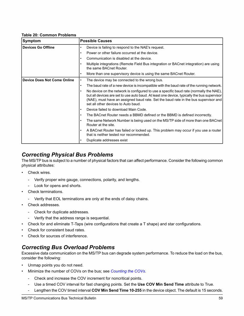
Table 20: Common ProblemsPossible CausesSymptom• Device is failing to respond to the NAE's request.• Power or other failure occurred at the device.• Communication is disabled at the device.• Multiple integrations (Remote Field Bus integration or BACnet integration) are using
the same BACnet Router.• More than one supervisory device is using the same BACnet Router.
Devices Go Offline
• The device may be connected to the wrong bus.• The baud rate of a new device is incompatible with the baud rate of the running network.• No device on the network is configured to use a specific baud rate (normally the NAE),
but all devices are set to use auto baud. At least one device, typically the bus supervisor(NAE), must have an assigned baud rate. Set the baud rate in the bus supervisor andset all other devices to Auto baud.
• Device failed to download Main Code.• The BACnet Router needs a BBMD defined or the BBMD is defined incorrectly.• The same Network Number is being used on the MS/TP side of more than one BACnet
Router at the site.• A BACnet Router has failed or locked up. This problem may occur if you use a router
that is neither tested nor recommended.• Duplicate addresses exist
Device Does Not Come Online
Correcting Physical Bus ProblemsTheMS/TP bus is subject to a number of physical factors that can affect performance. Consider the following commonphysical attributes:
• Check wires.
- Verify proper wire gauge, connections, polarity, and lengths.- Look for opens and shorts.
• Check terminations.
- Verify that EOL terminations are only at the ends of daisy chains.• Check addresses.
- Check for duplicate addresses.- Verify that the address range is sequential.
• Check for and eliminate T-Taps (wire configurations that create a T shape) and star configurations.• Check for consistent baud rates.• Check for sources of interference.
Correcting Bus Overload ProblemsExcessive data communication on the MS/TP bus can degrade system performance. To reduce the load on the bus,consider the following:
• Unmap points you do not need.• Minimize the number of COVs on the bus; see Counting the COVs.
- Check and increase the COV increment for noncritical points.- Use a timed COV interval for fast changing points. Set the Use COV Min Send Time attribute to True.- Lengthen the COV timed intervalCOVMin Send Time 10-255 in the device object. The default is 15 seconds.
59MS/TP Communications Bus Technical Bulletin

• Check for and correct unstable sensors.• Reduce the number of devices on the bus, if possible.• If running at less than 38.4k baud, increase the baud rate (if possible).• Verify repeaters, if applicable.
- Verify that repeaters are used where needed.- Verify that repeaters are configured and wired correctly.- Verify that BACnet Routers are associated with a single integration (Remote Field Bus) at a single supervisory
device.
Reading the Baud Rate of DevicesAttributes in the Metasys system UI display the baud rate settings and current baud rates of devices on the bus.Figure 29 shows an example of the baud rate attributes in the NCE.
If the NAE is connected to an MS/TP bus that is already communicating at an unknown baud rate, you can temporarilyset the NAE Field Bus Integration object Baud Rate Selection to Auto. You can then read the current baud rate fromthe Active Baud Rate attribute in the NAE.
To read the baud rates of devices, see the following table.
Table 21: Reading Baud Rates in the Metasys SMP User InterfaceTo Read the Baud Rate Setting and the Current Baud RateDevice
1. In the Metasys UI, display the Field Bus integration.2. Select the Hardware tab, Baud Rate Selection indicates the baud rate selection
specified for the NAE.3. On the Diagnostics tab, Active Baud Rate displays the current baud rate of the
bus.1
NAE
1. In the Metasys system UI, access the Field Bus integration.2. On the Engineering Tab, expand the field device object. Double-click the desired
MS/TP bus object.3. Baud Rate Selection indicates the baud rate selection specified for the field device.
Active Baud Rate displays the current baud rate of the bus.1
Field Device on the FC Bus2
1 This attribute displays the baud rate at which the device is currently communicating. If the device Baud Rate Selection is setto Auto, you can use this attribute to see what the baud rate actually is.
2 This applies to Johnson Controls field controllers.Metasys system TEC Series thermostats and third-party devices may havedifferent means of reporting the baud rate.
60MS/TP Communications Bus Technical Bulletin

Figure 29: MS/TP Master Summary Showing Baud Rates
Counting the COVsYou can check the COV report rates on the main device object Diagnostics tab of each device that supports thismeasurement. The two attributes are COV Tx Rate and COV Rcv Rate. The NAE COV Rcv Rate is the total for allconnected networks including the Ethernet and should not exceed 500 per minute. The COV Tx Rate counts onlythe reports originated by this device. Double clicking on the Trunk object at the top of the tree on the engineeringtab displays a list of devices, and the COVs TX, from devices that report this information. For more information onthese attributes, refer to the NAE Object and the MS/TP Field Device Object in the Metasys system Help.
Disabling a Device on the BusIf a device is causing communication problems, the Disable command from the Metasys system UI allows you totake the device offline. Once disabled, the device no longer sends or receives data, but remains in the token loopto maintain bus integrity and pass the token to the next device.
This procedure only prevents data related problems and has no effect on addressing or token loop problems.
Note: This command works on specific devices; it is not available on TEC Thermostat Controllers and may not beavailable on third-party devices.
To disable a device on the bus:
1. On the navigation tree, right-click the device you want to disable and select Commands from the pop-up menu.A dialog box appears for the device.
61MS/TP Communications Bus Technical Bulletin

2. SelectDisable and click Send. The device goes offline and a red X appears in front of the device in the navigationtree.
The device remains offline until you repeat this procedure and send the Enable command.
Changing the Baud Rate of an Entire BusThe following procedure represents recovery steps to synchronize the baud rate on the MS/TP bus. You may needto perform this procedure if:
• the baud rate of the bus supervisor (typically, the NAE) does not match that of the bus• you need to change the baud rate of the bus• you connect two buses operating at different baud rates
In general, we recommend that you set the bus supervisor (NAE) to 38,400 baud and set all of the other devices onthe bus to Auto.
Note: To change the baud rate of the bus, you need a Wireless Commissioning Converter (MS-BTCVT-1), and youneed access to the Metasys system UI and the laptop where CCT and the Wireless Utility are installed.
Note: A TEC26xx Thermostat Controller must not be the lowest numbered address on the bus.
To change the baud rate of a bus:
1. Connect the Wireless Commissioning Converter (MS-BTCVT-1) directly to the bus you want to change.
Important: This procedure disrupts bus communication until completed. Be sure you have connected theWireless Commissioning Converter to the correct bus before proceeding.
2. Start the Wireless Utility. (Refer to the Metasys CCT Bluetooth Technology Communication CommissioningGuide [LIT-12011038] for more information on the Wireless Utility.)
3. In the Metasys system UI, change all of the devices whose baud rate is manually specified (that is, not set toAuto) to the new baud rate.
Note: Change the baud rate of the bus supervisor last.4. Change the baud rate of all bus repeaters, bus modems, and third-party devices to the new baud rate.
Note: Devices may appear to go offline as you change baud rates.5. In theWireless Utility, specify the newBaud Rate, select Force New Baud Rate, and clickChange. This process
takes approximately 3 minutes.6. Once the Force New Baud Rate process is complete, access the Metasys system UI and verify the baud rate
from the UI and that all devices came online.
Note: If the old baud rate is still the active baud rate, a device on the bus may still be manually set to use theold baud rate.
Automatic Low Resources MonitoringResources such as available memory and internal queues are continually monitored by the BACnet® communicationssoftware including the IP communications and MS/TP components of the controllers. If any resource becomesoverloaded, the BACnet communications software reduces the throughput (throttles it back) to allow the controllera chance to recover.
Exceeded resources are classified into degrees of severity as follows:
• Warning means the resource is in short supply.• Trouble means the resource may cause some observable problems.• Alarm means the resource is causing observable problems.• Critical means the resource is almost exhausted and operation may fail.
62MS/TP Communications Bus Technical Bulletin
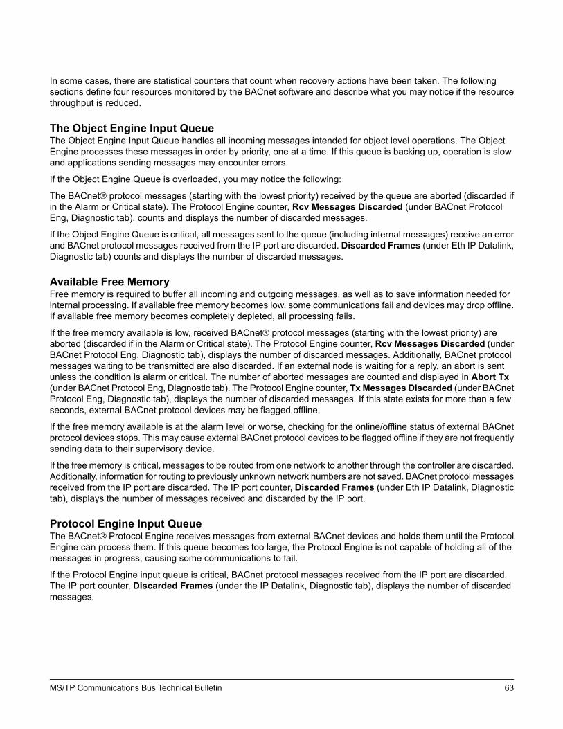
In some cases, there are statistical counters that count when recovery actions have been taken. The followingsections define four resources monitored by the BACnet software and describe what you may notice if the resourcethroughput is reduced.
The Object Engine Input QueueThe Object Engine Input Queue handles all incoming messages intended for object level operations. The ObjectEngine processes these messages in order by priority, one at a time. If this queue is backing up, operation is slowand applications sending messages may encounter errors.
If the Object Engine Queue is overloaded, you may notice the following:
The BACnet® protocol messages (starting with the lowest priority) received by the queue are aborted (discarded ifin the Alarm or Critical state). The Protocol Engine counter, Rcv Messages Discarded (under BACnet ProtocolEng, Diagnostic tab), counts and displays the number of discarded messages.
If the Object Engine Queue is critical, all messages sent to the queue (including internal messages) receive an errorand BACnet protocol messages received from the IP port are discarded. Discarded Frames (under Eth IP Datalink,Diagnostic tab) counts and displays the number of discarded messages.
Available Free MemoryFree memory is required to buffer all incoming and outgoing messages, as well as to save information needed forinternal processing. If available free memory becomes low, some communications fail and devices may drop offline.If available free memory becomes completely depleted, all processing fails.
If the free memory available is low, received BACnet® protocol messages (starting with the lowest priority) areaborted (discarded if in the Alarm or Critical state). The Protocol Engine counter, Rcv Messages Discarded (underBACnet Protocol Eng, Diagnostic tab), displays the number of discarded messages. Additionally, BACnet protocolmessages waiting to be transmitted are also discarded. If an external node is waiting for a reply, an abort is sentunless the condition is alarm or critical. The number of aborted messages are counted and displayed in Abort Tx(under BACnet Protocol Eng, Diagnostic tab). The Protocol Engine counter, TxMessages Discarded (under BACnetProtocol Eng, Diagnostic tab), displays the number of discarded messages. If this state exists for more than a fewseconds, external BACnet protocol devices may be flagged offline.
If the free memory available is at the alarm level or worse, checking for the online/offline status of external BACnetprotocol devices stops. This may cause external BACnet protocol devices to be flagged offline if they are not frequentlysending data to their supervisory device.
If the free memory is critical, messages to be routed from one network to another through the controller are discarded.Additionally, information for routing to previously unknown network numbers are not saved. BACnet protocol messagesreceived from the IP port are discarded. The IP port counter, Discarded Frames (under Eth IP Datalink, Diagnostictab), displays the number of messages received and discarded by the IP port.
Protocol Engine Input QueueThe BACnet® Protocol Engine receives messages from external BACnet devices and holds them until the ProtocolEngine can process them. If this queue becomes too large, the Protocol Engine is not capable of holding all of themessages in progress, causing some communications to fail.
If the Protocol Engine input queue is critical, BACnet protocol messages received from the IP port are discarded.The IP port counter, Discarded Frames (under the IP Datalink, Diagnostic tab), displays the number of discardedmessages.
63MS/TP Communications Bus Technical Bulletin
Protocol Engine Output Pending QueueThe BACnet® Protocol Engine has an output pending queue used to hold messages when slower communicationslinks, such as MS/TP, are not able to keep up with the rate at which outgoing messages are generated. If this queuebecomes too large, the time required to send a message becomes excessive, resulting in slow operation. When thisslow operation occurs, applications begin to encounter errors and some devices may drop offline. Messages thatare waiting are also counting down their APDU Timeout.
If the Protocol Engine output pending queue is in the trouble state or worse, reading the initial values at startup isdelayed.
If the Protocol Engine output pending queue is critical, originated outgoing messages are discarded and the sendingapplications receive an error.
64MS/TP Communications Bus Technical Bulletin

Appendix: Optimizing SA Bus TrafficThis appendix describes how to configure the devices on the Sensor Actuator (SA) bus if excessive traffic on thebus is causing delays in communication.
Apply the solutions if:
• Control applications on your site include multiple Input/Output Modules (IOMs) that use more than 8 analogoutputs (AOs) with fast control processes (time constant of less than 100 seconds)
• The SA bus has more than 4 IOM471x devices
You can also apply these solutions if:
• Analog input (AI) values on the SA bus report offline for a few seconds at a time. The IOM to which the AIs areconnected may not show offline at the same time.
• IOMs on the SA bus report offline for several seconds during startup or shutdown of processes involving multipleAO commands.
• Field Equipment Controllers (FECs) experience unusually high CPU usage.
The solution to this problem is to limit the fast, sensitive control processes that occur over the SA bus. Examples ofthis type of control include airflow, static pressure control, and room pressurization. Instead, leave these controlsystems on the FEC or Network Control Engine (NCE) itself, and move slower response or monitor only points onthe SA Bus.
The sections in this appendix provide detail on messages and command calculations and strategies that reduce SABus traffic.
Excessive TrafficSA Bus traffic includes change of value (COV) messages that are issued from inputs located on IOMs and commandsissued to outputs located on the IOMs. Excessive traffic is defined as more than 500 COVs per minute or more than500 commands per minute.
To resolve communication issues associated with excessive SA Bus traffic, reduce the number of COVs to fewerthan 500 per minute and the number of commands to fewer than 500 per minute.
Note: The limit of 500 commands per minute is an approximate maximum that assumes a 1 second token looptime. If your network is configured differently, the actual threshold for this problem may vary. For example,if your token loop time is 2 seconds, the maximum is 240. If you reduce traffic on the SA Bus to 500 and stillexperience this problem, or you are uncertain of your token loop time, we recommend you reduce commandtraffic to 240.
To find the number of COVs and commands on your SA Bus, see Inputs and COVs and Outputs and Commands.For strategies on reducing traffic on your SA Bus, see SA Bus Traffic Reduction.
Inputs and COVsThe COVs for all AIs on IOMs are fixed at .001. FEC s immediately acknowledge all SA Bus COV reports. The goalis to have the total number of COVs on an SA Bus be fewer than 500 per minute. Use the following table to determinethe total potential COVs per minute.
Note: The Update Interval (refresh rate for the user interface and Controller Configuration Tool [CCT] applications)depends on the Filter Setup, Process ID, and Time Constant attribute values in the Analog Input object. If afast process (time constant of less than 100 seconds) receives its input from sensors located on SA Busdevices, excessive bus traffic can result.
65MS/TP Communications Bus Technical Bulletin: Appendix: Optimizing SA Bus Traffic

Table 22: COV Rates: InputsApproximate COVs PerMinute
Update Interval(Hundredths of Seconds)
Time Constant (Seconds)Process ID
6010030Airflow
6010030Airflow %
6010030Airflow Difference
6010030Bldg Static
6010030Duct Static
6010030Pump Diff P
30200
100
60CHWS-T Mixing
3020060HWS-T Mixing
3020080MA-T
2030090CHWS-T HEX
2030090HWS-T HW HEX
2030090HWS-T Steam HEX
10600200DA-H
10600200DA-T
32,000600CWS-T
23,000900RA-H
23,000900ZN-H
23,000900ZN-T
23,000900ZN-T LC
23,000900ZN-H LC
For example, assume you have a Mixed Air Single Path, Variable Speed Supply fan with Volume matching system.The list of sensors includes discharge air temperature, mixed air temperature, duct static pressure, supply flow, andreturn flow. The following table shows how to calculate the COV rate.
Table 23: Change of Value Rate Calculation: InputsApproximate COVs PerMinute
Update Interval(Hundredths of Seconds)
Process IDSensor
60100Duct StaticDuct Static
60100AirflowSupply Flow
60100AirflowReturn Flow
30200MA-TMA-T
10600DA-TDA-T
220Total
When these sensors are located on SA Bus devices, 220 is the expected COV rate. This number is below themaximum of 500 COV, and no communication issues should result.
66MS/TP Communications Bus Technical Bulletin: Appendix: Optimizing SA Bus Traffic

Outputs and CommandsExcessive SA Bus traffic can also result when a fast process sends commands to multiple AOs on the SA Bus. AOcommands are sent every time the proportional-integral-derivative (PID) loop execution results in a new value. TheFEC can issue only 10 commands on the SA Bus per pass of the token. If excessive AO commands are generated,the output queue may fill up, and the issuance of commands may be delayed for several token loop times. In addition,the BACnet protocol engine in the controller may become overwhelmed and discard messages when the total pendingqueue count exceeds 50 messages. This state can result in AOs or the IOM appearing offline for short periods oftime.
A healthy SA bus should not exceed 20 for the Maximum Output Queue Used value because that value requires 2token passes to issue the commands. Use the following table to determine the command rate per minute on the SABus. The goal is to have the total number of commands under the 500 per minute with a 1 second or less token looptime.
Table 24: Command Rates: OutputsApproximate CommandRate Per Minute
PID Interval (Seconds)Time Constant (Seconds)Process ID
61090CHWS-T HEX
61090HWS-T HW HEX
61090HWS-T Steam HEX
512200DA-H
512200DA-T
51280MA-T
160600CWS-T
160900RA-H
160900ZN-H
160900ZN-T
160900ZN-T LC
160900ZN-H LC
For example, assume you have a Mixed Air Single Path, Variable Speed Supply fan with Volume Matching system.The control loops include discharge control, duct status pressure control, and return fan flow control. Use the followingtable to calculate the command rate per minute.
Table 25: Command Rate Calculation: OutputsCommand Rate PerMinute
PID Interval (Seconds)Process IDControl Loop
601Duct StaticDuct Static Pressure Control
601AirflowReturn Fan Flow Control
512DA-TDischarge Control
125Total
When the outputs are located on SA Bus devices, 125 is the expected command rate per minute. This number isbelow the maximum of 500 commands per minute, and no communication issues result.
67MS/TP Communications Bus Technical Bulletin: Appendix: Optimizing SA Bus Traffic

SA Bus Traffic ReductionIf the COV rate exceeds 500 for inputs or the command rate exceeds 500 for outputs, use the following strategiesto reduce the traffic on your SA Bus:
• If possible, connect fast process inputs and outputs directly to the FEC/Network Control Engine (NCE). Fastprocesses include airflow, static or differential pressure control, central plant temperature control, and mixed aircontrol. Move slower process inputs and outputs on the FEC/NCE to devices on the SA Bus, and move the inputsand outputs for the fast processes to the FEC/NCE. The FEC/NCE internal update process does not contributeto SA Bus communication issues.
• Limit the number of processes controlled across the SA Bus to use 8 AOs or fewer.• If an IOM is used strictly for monitoring, place the device on the Field Controller (FC) Bus instead of the SA Bus.
Alternatively, relocate AIs used for monitoring to a separate IOM on the FC Bus.• If the AIs must remain on the SA Bus, configure the Filter Setup attribute to monitor only. If the AI is part of a
process, reduce the resulting update interval by modifying the time constant attribute of the analog input objectwith the following steps:1. Set the Filter Setup attribute to the value Process Data.2. Set the Time Constant attribute to 0.3 times the desired update interval value. This configuration allows the
low pass filter to continue to operate properly.Note: Update interval has units of hundredths of a second. A time constant of 30 results in a 1 second
update interval (displayed as 100 hundredths of a second).• If you must leave inputs on the SA bus, slow down the process unless it will affect Pattern Recognition Adaptive
Control (PRAC).Important: Use caution. Changing the PID interval or the analog input filtering may affect the PID controller’s
ability to provide proper control. This change also may affect the adaptive tuner’s ability to tune thecontrol process. Make sure that the AI has an update interval less than or equal to the PID interval.We recommend an AI update interval that is half the PID interval or less.
Change the inputs of the PID Pre Processor logic block in the Controller Configuration Tool (CCT) to match thecurrent outputs (Table 26). Refer to the PID Pre-Processor section of the Controller Tool Help (LIT-12011147)for details on this block.
Table 26: Inputs and Matching OutputsNotesPID Pre-Processor Block OutputsPID Pre-Processor Inputs
--Eff Process RangeProcess Range
--Eff Time ConstantTime Constant
--Eff Process Dead TimeProcess Dead Time
For the Interval value, add severalseconds to the Eff Period value. Intervalshould be in the range of TimeConstant/10 to Time Constant/5.
Eff Period
(Release 5.1 and later)
Interval
--Eff Proportional Band
(Release 5.1 and later)
Proportional Band
--Eff Integral Time (Release 5.1 or later)Integral Time
--Eff Saturation Time (Release 5.1 or later)Saturation Time
--FalseStandard Tuning
68MS/TP Communications Bus Technical Bulletin: Appendix: Optimizing SA Bus Traffic

Building Technologies & Solutions507 E. Michigan Street, Milwaukee, WI 53202
Johnson Controls® is a registered trademark of Johnson Controls.All other marks herein are the marks of their respective owners.© 2017 Johnson Controls
www.johnsoncontrols.comPublished in U.S.A.
69MS/TP Communications Bus Technical Bulletin: Appendix: Optimizing SA Bus Traffic